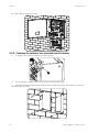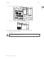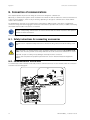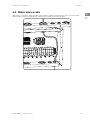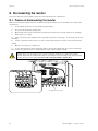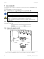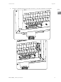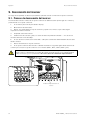
1
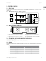
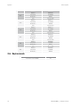
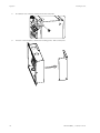
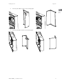
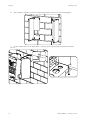
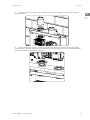
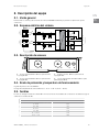
Combiner Box
INGECON SUN 3Play TL U M
Installation manual
Manual de instalación
ABI2014IQM03_
03/2015
Ingeteam Inc
3550 W. Canal St.
Milwaukee, WI 53208 - USA
Tel.: +1 (414) 934 4100
Fax.: +1 (414) 342 0736
e-mail: [email protected]
Service Call Center: +1 (414) 934 4158
Ingeteam Power Technology, S.A. - Energy
Avda. Ciudad de la Innovación, 13
31621 SARRIGUREN (Navarra) - Spain
Tel.: +34 948 28 80 00
Fax.: +34 948 28 80 01
e-mail: [email protected]
Service Call Center: +34 948 698 715
Ingeteam
English
EN
Español
ES
iii
Ingeteam
The copy, distribution or use of this document or of its content requires written authorisation. Any breach thereof will be reported for
damages. All rights reserved including those of patent rights or design registration.
The conformity of the document content with the hardware described has been checked. However, discrepancies may exist. Liability
will not be assumed for total concordance. The information contained in this document is regularly reviewed and it is possible that
there may be changes in subsequent editions. Other functions may be available which are not covered by this document.
This document may be changed.
La copia, circulación o uso de este documento o de su contenido requiere un permiso por escrito. Su incumplimiento será
denunciado por daños y perjuicios. Todos los derechos están reservados, incluyendo aquellos que resulten de derechos de patentes
o registro del diseño.
La correspondencia del contenido del documento con el hardware ha sido comprobada. Sin embargo, pueden existir discrepancias.
No se asume ninguna responsabilidad por la concordancia total. La información que contiene este documento es revisada
regularmente y es posible que se produzcan cambios en siguientes ediciones.
El presente documento es susceptible de ser modificado.
iv
Important Safety Instructions
Ingeteam
Important Safety Instructions
EN
This section describes the safety warnings and the Personal Protective Equipment used in the unit.
ES
Safety conditions
General warnings
The operations described in this manual may be performed only by qualified personnel.
The status of qualified personnel referred to in this manual will be, as a minimum, that which meets
all the standards, regulations and laws regarding safety applicable to the tasks of installing and
operating this unit.
You must comply with all applicable safety-related legislation for electrical work. Danger of electric
shock.
Compliance with the safety instructions set out in this manual or in the suggested legislation does
not imply exemption from other specific standards for the installation, place or country.
Opening the door of the housing does not imply there is no voltage inside.
There is a risk of electric shock even after disconnecting all power sources from the system.
Only qualified personnel may open it, following the instructions in this manual.
The entire manual must be read and understood in full prior to manipulating, installing or operating
the unit.
Carry out all control and handling without voltage.
As a minimum security measure in this operation, you must always follow the so-called 5 golden
rules:
1.
Disconnect.
2.
Prevent any possible feedback.
3.
Check there is no voltage.
4.
Ground and short circuit.
5.
Protect from live elements, if any, and put up safety signs around the work area.
Until you have completed these five steps, the work area cannot be considered voltage-free and any
work performed will be considered to be work on live equipment.
Category III - 1000-Volt measuring instruments must be used for checking for the absence of voltage.
Ingeteam accepts no liability for any damages caused by improper use of the equipment. You must
propose in advance to Ingeteam any work carried out on any equipment which implies a modification
of the original electrical arrangements. These must be studied and approved by Ingeteam.
ABI2014IQM03_ - Installation manual
5
Important Safety Instructions
Ingeteam
Potential hazards for people
Bear in mind the following warnings concerning personal safety.
The equipment may remain charged after disconnecting the renewable power supply.
Carefully follow the mandatory steps in the manual for removing the voltage.
Always follow the indications in the manual on moving and placing the unit.
Potential hazards for the equipment
Bear in mind the following warnings concerning protection of the equipment.
After all duly authorized handling, check that the combiner box is ready to start operation. Only after
this can you connect it, following the instructions in the manual.
Do not disconnect or connect any terminal while the inverter is operating. Disconnect and check for
absence of voltage first.
Personal Protective Equipment (PPE)
When working on the unit, use the following safety equipment recommended by Ingeteam as a minimum.
Name
Explanation
Safety footwear
In compliance with standard ANSI Z41.1-1991
Helmet with face shield
In compliance with standard ANSI Z89.1-2014, provided there are elements
with directly accessible voltage.
Working clothes
Close-fitting, non-flammable, 100% cotton
Dielectric gloves
In compliance with standard ASTM D 120-87
Tools and / or equipment used in live work must have at least Category III-1000 Volts insulation.
Should the country’s regulations demand another kind of personal protection, you should appropriately supplement
the equipment recommended by Ingeteam.
6
ABI2014IQM03_ - Installation manual
Contents
Ingeteam
Contents
EN
Important Safety Instructions........................................................................................................................ 5
Safety conditions.................................................................................................................................... 5
Personal Protective Equipment (PPE)....................................................................................................... 6
Contents .................................................................................................................................................... 7
1. About this manual................................................................................................................................... 8
1.1. Recipients...................................................................................................................................... 8
1.2. Symbols......................................................................................................................................... 8
2. Unit description...................................................................................................................................... 9
2.1. Overview........................................................................................................................................ 9
2.2. Electrical diagram of the system....................................................................................................... 9
2.3. Description of accesses................................................................................................................... 9
2.4. Protection rating and operating temperature...................................................................................... 9
2.5. Fuses............................................................................................................................................ 9
2.6. Replacements.............................................................................................................................. 10
3. Receipt of the unit and storage............................................................................................................... 11
3.1. Reception.................................................................................................................................... 11
3.2. Transport damage......................................................................................................................... 11
3.3. Storage........................................................................................................................................ 11
3.4. Conservation................................................................................................................................ 11
4. Preparation for installing the unit........................................................................................................... 12
4.1. Environment................................................................................................................................. 12
4.2. Environmental conditions.............................................................................................................. 12
4.3. Supporting Surface and Fastening.................................................................................................. 13
5. Installing the unit................................................................................................................................. 14
5.1. General requirements for installation.............................................................................................. 14
5.2. Opening the housing..................................................................................................................... 14
5.3. Fastening the combiner box to the wall........................................................................................... 14
5.3.1. Fastening the combiner box next to the inverter....................................................................... 15
5.3.2. Fastening the combiner box separated from the inverter........................................................... 20
6. Connection of communications............................................................................................................... 22
6.1. Safety instructions for connecting accessories................................................................................. 22
6.2. Communication via RS-485........................................................................................................... 22
6.3. Modem antenna cable................................................................................................................... 23
7. DC connection...................................................................................................................................... 24
7.1. Safety instructions for the DC connection........................................................................................ 24
7.2. Wiring requirements for the DC connection...................................................................................... 24
7.3. DC connection process.................................................................................................................. 24
8. Start-up............................................................................................................................................... 27
8.1. Equipment inspection................................................................................................................... 27
8.1.1. Inspection............................................................................................................................ 27
8.1.2. Hermetic sealing of the unit.................................................................................................. 27
8.2. Power-up...................................................................................................................................... 27
9. Disconnecting the inverter..................................................................................................................... 28
9.1. Process of disconnecting the inverter.............................................................................................. 28
10. Preventive maintenance....................................................................................................................... 29
10.1. Safety conditions........................................................................................................................ 29
10.2. Condition of the housing.............................................................................................................. 29
10.3. Condition of cables and terminals................................................................................................. 29
10.4. Environment............................................................................................................................... 29
10.5. Checking the DC fuses................................................................................................................ 29
11. Waste handling................................................................................................................................... 30
ABI2014IQM03_ - Installation manual
7
ES
About this manual
Ingeteam
1. About this manual
This manual describes the INGECON SUN 3Play U inverter combiner boxes and provides information for their
correct reception, installation and maintenance.
1.1. Recipients
This document is intended for qualified personnel.
The status of qualified personnel referred to in this manual will be, as a minimum, that which meets all the
standards, regulations and laws regarding safety applicable to the tasks of installing and operating this unit.
The responsibility for designating qualified personnel will always fall to the company to which the personnel
belong. It is necessary to decide which workers are suitable or not for carrying out specific work to preserve their
safety at the same time as complying with occupational safety legislation.
These companies are responsible for providing appropriate training in electrical equipment to their personnel and
for familiarizing them with the contents of this manual.
1.2. Symbols
This manual uses various symbols to emphasize and highlight certain texts. The general meanings are explained
below.
General warning.
Read the section indicated in this manual.
Electrical danger.
Prohibition.
General information.
8
ABI2014IQM03_ - Installation manual
Unit description
Ingeteam
2. Unit description
EN
2.1. Overview
ES
In order to facilitate the connection and disconnection of the INGECON SUN 3Play inverter, it is possible to add a
combiner box.
2.2. Electrical diagram of the system
Inverter
L1
PV array 1
MPPT1
L2
L2
Filter
PV array 2
L3
L1
L3
AFCI
N
N
Connection to the grid
AFCI
MPPT2
Combiner box
2.3. Description of accesses
A
B
C
D
A. DC1 supply access. Holes for 1 1/2 inch gas
coupling.
C. Communications. Holes for 3/4 inch gas
coupling.
B. DC2 supply access. Holes for 1 1/2 inch gas
coupling.
D. Access for modem antenna. Hole for M16
packing gland.
2.4. Protection rating and operating temperature
The protection rating is NEMA 4.
The temperature operating range is -13 ºF ~ 149 ºF (-25 ºC ~ 65 ºC).
2.5. Fuses
20 A gauge fuses are supplied as standard. Depending on the needs of the installation, the DC fuse gauge must be
selected.
DC Fuses
Maximum string power (Impp)
Fuse gauge
4 ~ 4.5 A
6 A
4.5 ~ 6 A
8 A
6 ~7.5 A
10 A
7.5 ~ 9 A
12 A
9 ~ 11.25 A
15 A
11.25 ~ 12 A
20 A
ABI2014IQM03_ - Installation manual
9
Unit description
Ingeteam
Gauge
20 A
15 A
12 A
10 A
8 A
6 A
Manufacturer
Manufacturer reference
Littlefuse
0SPF020.T
Bussmann
PV-20A10F
DF Electrics
491635
Siba
50 215 28.20
Littlefuse
0SPF015.T
Bussmann
PV-15A10F
DF Electrics
491629
Siba
50 215 28.15
Littlefuse
0SPF012.T
Bussmann
PV-12A10F
DF Electrics
491625
Siba
50 215 28.12
Littlefuse
0SPF010.T
Bussmann
PV-10A10F
DF Electrics
491620
Siba
50 215 28.10
Littlefuse
0SPF008.T
Bussmann
PV-8A10F
DF Electrics
491615
Siba
50 215 28.8
Littlefuse
0SPF006.T
Bussmann
PV-6A10F
DF Electrics
491610
2.6. Replacements
10
Description
Quantity
Bussman Fuse PV-20A10F
16
ABI2014IQM03_ - Installation manual
Receipt of the unit and storage
Ingeteam
3. Receipt of the unit and storage
EN
3.1. Reception
ES
Keep the unit in its packaging until immediately before installation.
3.2. Transport damage
If the unit has been damaged during transport, proceed as follows:
1.
Do not proceed with the installation.
2.
Notify the distributor immediately within five days of receipt of the unit.
If ultimately you must return the unit to the manufacturer, you must use the original packaging.
3.3. Storage
Failure to follow the instructions in this section may lead to damage to the unit.
Ingeteam accepts no liability for damage resulting from the failure to follow these instructions.
If the unit is not installed immediately after reception, take into account the following points in order to avoid
damage:
•
The unit must be stored in its original packaging.
•
Keep the unit free of dirt (dust, shavings, grease, etc.) and away from rodents.
•
Keep it away from water splashes, welding sparks, etc.
•
Cover the unit with a breathable protective material in order to prevent condensation due to ambient
humidity.
•
It is very important to protect the unit from chemical products which can cause corrosion, as well as from
salty atmospheres.
•
Do not store the unit outdoors.
3.4. Conservation
In order to permit correct conservation of the units, they must not be removed from their original packaging until it
is time to install them.
In case of prolonged storage, the use of dry places avoiding, as far as possible, sharp changes in temperature is
recommended.
Deterioration of the packaging (tears, holes, etc.) prevents the units from being kept in optimum conditions before
installation. Ingeteam accepts no liability in the case of failing to observe this condition.
ABI2014IQM03_ - Installation manual
11
Preparation for installing the unit
Ingeteam
4. Preparation for installing the unit
When deciding the location of the unit and planning your installation, you must follow a set of guidelines based on
the specifications of the unit. These guidelines are summarized in this chapter.
4.1. Environment
•
Situate the units in a place which is accessible for installation and maintenance work.
•
Avoid corrosive environments that may affect the proper operation of the unit.
•
Never place any object on top of the unit.
•
Do not expose the inverters to direct sunlight.
4.2. Environmental conditions
Environmental operating conditions indicated in section “2.4. Protection rating and operating temperature” must
be taken into account when choosing the location of the unit.
Take into account that moderate condensation may occasionally occur as a consequence of temperature variations.
For this reason, apart from the unit's own protection, it is necessary to monitor these units once they have been
started up on sites where the conditions described above are not expected to be present.
In the event of condensation, never apply voltage to the unit.
12
ABI2014IQM03_ - Installation manual
Preparation for installing the unit
Ingeteam
4.3. Supporting Surface and Fastening
EN
The combiner box must be installed in accordance with the specifications in the following figure. The permitted
positive inclination is between the range of 15 to 90º. The installation with negative inclination (example on the
right) is not permitted.
ES
9
15º
0º
Reserve a solid wall to which to attach the unit. It must be possible to drill the wall and fit suitable wall anchors
and self-tapping screws to support the unit’s weight.
ABI2014IQM03_ - Installation manual
13
Installing the unit
Ingeteam
5. Installing the unit
Before installing the unit, you must remove the packaging, taking special care not to damage the housing.
Check that there is no condensation inside the packaging. If there are signs of condensation, the unit must not be
installed until you are sure it is completely dry.
All installation operations must comply with current regulations.
All operations involving moving heavy weights must be carried out by two people.
5.1. General requirements for installation
•
The environment of the unit must be appropriate and meet the guidelines described in Chapter “4.
Preparation for installing the unit”. Additionally, the parts used in the rest of the installation must be
compatible with the unit and comply with the applicable legislation.
•
Ventilation and the space for work must be suitable for maintenance tasks according to the applicable
regulations in force.
•
The external connection devices must be suitable and sufficiently close as set forth in current regulations.
•
The feed cables must be of the appropriate gauge for the maximum current.
5.2. Opening the housing
To install the combiner box, firstly it is necessary to open the housing. Remove the six front screws to open the
housing.
5.3. Fastening the combiner box to the wall
The combiner boxes can be installed in two different ways: next to inverter or separated from it. The installation
processes for each cases are described below.
14
ABI2014IQM03_ - Installation manual
Installing the unit
Ingeteam
5.3.1. Fastening the combiner box next to the inverter
EN
1. Use the template supplied with the combiner box to mark the holes to be made in the wall, always
respecting the distances regarding the inverter anchor points. Drill the necessary holes.
3.66 in (93 mm)
ES
8.66 in (220 mm)
8.66 in (220 mm)
25.98 in (660 mm)
5.24 in (133 mm)
11.5 in (292 mm)
6.93 in (176 mm)
13.94 in (354 mm)
ABI2014IQM03_ - Installation manual
15
Installing the unit
Ingeteam
16
2.
Unscrew the four side bolts and remove the two rear plates.
3.
For each of the rear plates, observe the following points. Take out the plate.
ABI2014IQM03_ - Installation manual
Installing the unit
4.
Ingeteam
Turn the plate 180º as shown in the following figure.
EN
ES
180º
5.
Turn the plate 90º as shown in the following figure.
90º
ABI2014IQM03_ - Installation manual
17
Ingeteam
6.
Installing the unit
Bolt the plate to the wall. The result of fastening both plates can be seen in the following figure.
7. Fit the combiner box onto the plates. Once it is fitted, secure it by fastening the two bolts removed in
point 2.
18
ABI2014IQM03_ - Installation manual
Installing the unit
Ingeteam
8. Install the ducts in the combiner box. To maintain the protection rating, the insulating seals supplied
must be installed.
EN
ES
9. Hang the inverter from its plate, inserting the combiner box ducts into the bottom holes of the inverter.
Secure the ducts inside the inverter using the supplied nuts. The insulating seal must be installed between the
duct and the inverter, on the outside of the latter.
ABI2014IQM03_ - Installation manual
19
Installing the unit
Ingeteam
10. Check that the installation is firm.
5.3.2. Fastening the combiner box separated from the inverter
1.
Unscrew the four side bolts and remove the two rear plates.
2.
Use the template to mark the four holes necessary to fasten the rear plates.
3. Fasten the rear plates using fastening elements that are suitable for the wall. The diameter of the holes of
the plate is 0.31 in (8 mm).
20
ABI2014IQM03_ - Installation manual
Installing the unit
4.
Ingeteam
Connect the combiner box onto the rear plates.
EN
ES
5.
Fasten the four side bolts, thus fixing the combiner box to the plates.
Once the installation is complete, proceed to make the connections in the following order:
1.
Connection of communications (optional).
2.
DC connection.
It is mandatory to follow the order described above. Do not switch on the power until you have made
all the connections and closed the unit.
ABI2014IQM03_ - Installation manual
21
Connection of communications
Ingeteam
6. Connection of communications
This chapter explains the process for wiring the connections through the combiner box.
Optionally, a communication system can be installed in the inverter in order to establish a connection with the unit
to monitor and configure it, either locally or remotely, depending on the type of communication chosen and the
needs of the installation.
As standard these units have local communication via RS-485. In addition there is the option of establishing
connections using other technology types. Connection via RS-485 is specified in this section, in addition to routing
the modem antenna cable in the event it is installed.
See the corresponding communication accessories manual and the inverter installation and operation
manual for further information.
Read carefully before starting the connection process.
6.1. Safety instructions for connecting accessories
Consult section “Important Safety Instructions” and the following instructions before working on the
unit.
Make sure there is no voltage present on the unit before starting the connection. Do not switch on the
power to the unit until you have successfully made the rest of the connections and the unit is closed.
Ingeteam accepts no liability for any damages caused by incorrect connection.
Use the personal protective equipment specified in the section “Personal Protective Equipment
(PPE)”.
6.2. Communication via RS-485
To communicate several inverters via RS-485, create a communication bus. In each inverter, make the connection
as shown in the following figure.
22
ABI2014IQM03_ - Installation manual
Connection of communications
Ingeteam
6.3. Modem antenna cable
EN
Optionally, it is possible to install a modem in the inverter to perform communications. In this case, the modem
antenna cable must be routed though the combiner box as shown in the following figure.
ABI2014IQM03_ - Installation manual
ES
23
DC connection
Ingeteam
7. DC connection
This chapter explains the requirements and process for wiring the DC wiring to the combiner box.
Read carefully before starting the connection process.
7.1. Safety instructions for the DC connection
Consult section “Important Safety Instructions” and the following instructions before working on the
unit.
Make sure there is no voltage present on the unit before starting the connection. Do not switch on the
power to the unit until you have successfully made the rest of the connections and the unit is closed.
Ingeteam accepts no liability for any damages caused by incorrect connection.
Use the personal protective equipment specified in the section “Personal Protective Equipment
(PPE)”.
7.2. Wiring requirements for the DC connection
Use copper cables.
DC wiring gauge
Minimum gauge
AWG 12
Maximum gauge
AWG 2
7.3. DC connection process
1.
Remove the caps of the pre-established holes for the DC connection.
2. Install the couplings, not forgetting the insulating seals, and insert the plastic tubes that route the cable
though said couplings. Make sure the couplings are closed, following the manufacturer's instructions.
24
ABI2014IQM03_ - Installation manual
DC connection
3.
Ingeteam
Insert the cable originating from the PV array and connect it respecting the polarities.
EN
ES
PV1+
+ PV1+
PV1+ PV1
PV1- PV1PV1- PV1
PE
PE
PE
PE
PE
PV2+
+ PV2+
PV2+ PV2
PE
ABI2014IQM03_ - Installation manual
PE
PV2- PV2PV2- PV2
PE
PE
PE
25
DC connection
Ingeteam
4.
Route the cable from the combiner box to the inverter and make the connections.
PV1+ PV1-
PV1+ PV1-
PE
PV2+ PV2-
PV2+ PV2-
XPV1+ XPV1-
XPV1+ XPV1-
PE
XPV2+ XPV2-
XPV2+ XPV2PE
PE
5.
26
Ensure the connections are firm.
ABI2014IQM03_ - Installation manual
Start-up
Ingeteam
8. Start-up
EN
This chapter details the process for the starting up the unit.
ES
8.1. Equipment inspection
You must check the correct condition of the installation before start-up.
Each installation is different, depending on its characteristics, the country in which it is located or other special
conditions which may apply. In all cases, before starting up, it is necessary to ensure that the installation complies
with the applicable legislation and regulations and that at least the part to be started up is complete.
8.1.1. Inspection
Before inverter start-up, you must carry out a general inspection of the units involving mainly:
Wiring inspection
•
Check that the cables are correctly joined to their connectors.
•
Check that these cables are in a good condition and that there are no hazards in their environment which
damage them, such as sources of intense heat, objects which could cut them or arrangements which put them
at risk of impacts or pulling.
•
Check the polarities of the cables.
Check that the unit is properly secured
Check that the unit is secured firmly and is not at risk of falling.
8.1.2. Hermetic sealing of the unit
Ensure during installation operations that the unit's level of sealing has not been altered during connection of the
unit.
Check the correct adjustment of the connectors and that any couplings and packing glands are well sealed.
8.2. Power-up
Once a general visual inspection, wiring check and sealing check have been carried out, connect power to the unit
following its installation and operation manual.
ABI2014IQM03_ - Installation manual
27
Disconnecting the inverter
Ingeteam
9. Disconnecting the inverter
This section describes the procedure to disconnect the inverter from the combiner box.
9.1. Process of disconnecting the inverter
When disconnecting the inverter from the combiner box firstly the inverter must be actuated upon, and then the
combiner box.
1.
In the inverter, proceed to the stop mode using the display.
2.
Disconnect the alternating voltage (Vac).
3.
Open the DC switch of the combiner box and wait five minutes for the internal capacitors to discharge.
4.
Check there is no voltage.
5. Signal cut-off point (Vac and Vdc) with a sign reading ¨Caution no switching…¨. If necessary, rope off the
work area.
PV1-
PE
PV2+ PV2-
6. If there is RS-485 communication or a cable for the modem antenna PV1+
it must be disconnected from the
inverter.
7.
Open the housing of the combiner box.
8. In the combiner box disconnect the wiring shown in the following figure from the connection terminals
that connect the combiner box to the inverter (XPV1+, XPV1-, XPV2+, XPV2- and PE).
PV1+ PV1-
PE
PV2+ PV2-
The DC switch cuts the voltage at the connection terminals between the combiner box and the
inverter. Despite the fact that the DC switch is open there will still be voltage in the inputs from the
PV array and at the fuse holders. Do not touch the connection terminals of the PV array.
XPV1+ XPV1-
XPV1+ XPV1-
XPV2+ XPV2-
XPV2+ XPV2PE
PE
28
Energized PV array input
ABI2014IQM03_ - Installation manual
Preventive maintenance
Ingeteam
10. Preventive maintenance
EN
The recommended preventive maintenance tasks must be carried out at least annually, except where otherwise
stated.
ES
10.1. Safety conditions
You must consider the set of conditions listed below as minimum requirements.
Before opening the unit, you must remove the power (see Section “9. Disconnecting the inverter”).
An open housing never implies an absence of voltage in the unit, so only qualified personnel may
access the unit, following the safe operation guidelines stipulated in this document.
Ingeteam accepts no liability for any damages caused by improper use of the equipment. You must
propose in advance to Ingeteam any work carried out on any equipment which implies a modification
of the original electrical arrangements. These must be studied and approved by Ingeteam.
All the maintenance checks included here must be carried out with the machine stopped, under safe
conditions for handling, including those specified by the client for these types of operation.
When carrying out maintenance work on the unit, you must wear the personal protective equipment
specified in Section “Personal Protective Equipment (PPE)” of this document.
After completing the maintenance task, replace the front cover and secure it with the bolts supplied.
10.2. Condition of the housing
A visual check of the condition of the housing must be carried out, confirming the condition of the seals and the
cover, as well as the fixing of the units to their anchor points on the wall. In addition, you must check the condition
of the housing for dents or scratches that might degrade the housing or cause it to lose its protection classification.
If these types of defect are noticed, the affected parts must be repaired or replaced.
Check that there is no moisture inside the housing. If moisture exists, dry it before making electrical connections.
Check the correct fixing of the housing components to their corresponding anchoring points.
Check the door seal of the unit is in good condition.
10.3. Condition of cables and terminals
•
Check the correct path of the cables so they do not come into contact with live parts.
•
Check the insulation deficiencies and hot spots by checking the color of the insulation and terminals.
•
Check that the connections are properly adjusted.
10.4. Environment
Check the environment to avoid amplifying or transmitting the buzzing sound.
10.5. Checking the DC fuses
It is advisable to regularly check the DC fuses.
ABI2014IQM03_ - Installation manual
29
Waste handling
Ingeteam
11. Waste handling
At the end of the unit's life, the waste must be correctly processed by an authorized hazardous
waste management company.
30
ABI2014IQM03_ - Installation manual
Condiciones importantes de seguridad
Ingeteam
Condiciones importantes de seguridad
EN
A lo largo de este apartado se detallan los avisos de seguridad así como el Equipo de Protección Individual.
ES
Condiciones de seguridad
Avisos generales
Las operaciones detalladas en este manual solamente pueden ser realizadas por personal cualificado.
La condición de personal cualificado a la que se refiere este manual, será como mínimo aquella que
satisfaga todas las normas, reglamentos y leyes en materia de seguridad aplicables a los trabajos de
instalación y operación de este equipo.
Se recuerda que es obligatorio cumplir toda la legislación aplicable en materia de seguridad para el
trabajo eléctrico. Existe peligro de descarga eléctrica.
El cumplimiento de las instrucciones de seguridad expuestas en este manual o de la legislación
sugerida no exime del cumplimiento de otras normas específicas de la instalación, el lugar o el país.
La apertura de la envolvente no implica la ausencia de tensión en su interior.
Existe peligro de descarga eléctrica incluso después de desconectar todas las fuentes de energía del
sistema.
Solamente podrá abrirla personal cualificado siguiendo las instrucciones de este manual.
Es obligatorio leer y entender el manual por completo antes de comenzar a manipular, instalar u
operar el equipo.
Realizar todas las maniobras y manipulaciones sin tensión.
Como medida mínima de seguridad en esta operación, se deberán observar las llamadas 5 reglas de
oro:
1.
Desconectar.
2.
Prevenir cualquier posible realimentación.
3.
Verificar la ausencia de tensión.
4.
Poner a tierra y en cortocircuito.
5. Proteger frente a elementos próximos en tensión, en su caso, y establecer una señalización
de seguridad para delimitar la zona de trabajo.
Hasta que no se hayan completado las cinco etapas, no podrá autorizarse el trabajo sin tensión y se
considerará trabajo en tensión en la parte afectada.
Es obligatorio para comprobar ausencia de tensión utilizar elementos de medida de categoría
III-1000 Voltios.
Ingeteam no se responsabiliza de los daños que pudieran causarse por una utilización inadecuada
de los equipos. Toda intervención que se realice sobre cualquiera de estos equipos que suponga un
cambio en las disposiciones eléctricas respecto a las originales deberán ser previamente propuestas a
Ingeteam. Éstas deberán ser estudiadas y aprobadas por Ingeteam.
ABI2014IQM03_ - Manual de instalación
31
Condiciones importantes de seguridad
Ingeteam
Peligros potenciales para las personas
Se han de tener en cuenta los siguientes avisos con el fin de proteger su seguridad.
El equipo puede permanecer cargado después de desconectar las fuentes de energía renovable.
Seguir cuidadosamente los pasos para quitar tensión obligados en el manual.
Seguir siempre las indicaciones del manual para mover y emplazar el equipo.
Peligros potenciales para el equipo
Se han de tener en cuenta los siguientes avisos con el fin de proteger el equipo.
Después de toda manipulación debidamente autorizada, comprobar que la caja de conexiones está
preparada para empezar a funcionar. Solamente después se puede proceder a conectarla siguiendo
las instrucciones del manual.
No desconectar o conectar ningún terminal mientras el inversor está funcionando. Desconectar y
comprobar la ausencia de tensión antes.
Equipo de Protección Individual (EPI)
Siempre que se trabaje en el equipo usar, como mínimo, el siguiente equipamiento de seguridad recomendado por
Ingeteam.
Denominación
Explicación
Calzado de seguridad
Conforme a la norma ANSI Z41.1-1991
Casco con pantalla facial
Conforme a la norma ANSI Z89.1-2014, siempre que existan elementos con
tensión directamente accesibles
Ropa de trabajo
Ceñida al cuerpo, no inflamable, 100% de algodón
Guantes dieléctricos
Conforme a la norma ASTM D 120-87
Las herramientas y/o equipos empleados en trabajos en tensión deben poseer, al menos, aislamiento de categoría
III-1000 Voltios.
En caso de que normativas propias del lugar exijan otro tipo de equipo de protección individual, el equipo
recomendado por Ingeteam se deberá completar adecuadamente.
32
ABI2014IQM03_ - Manual de instalación
Contenidos
Ingeteam
Contenidos
EN
Condiciones importantes de seguridad......................................................................................................... 31
Condiciones de seguridad...................................................................................................................... 31
Equipo de Protección Individual (EPI).................................................................................................... 32
Contenidos ............................................................................................................................................... 33
1. Información sobre este manual............................................................................................................... 34
1.1. Destinatarios................................................................................................................................ 34
1.2. Simbología................................................................................................................................... 34
2. Descripción del equipo.......................................................................................................................... 35
2.1. Visión general............................................................................................................................... 35
2.2. Esquema eléctrico del sistema....................................................................................................... 35
2.3. Descripción de accesos................................................................................................................. 35
2.4. Grado de protección y temperatura de funcionamiento..................................................................... 35
2.5. Fusibles....................................................................................................................................... 35
2.6. Repuestos.................................................................................................................................... 36
3. Recepción del equipo y almacenamiento................................................................................................. 37
3.1. Recepción.................................................................................................................................... 37
3.2. Daños en el transporte................................................................................................................... 37
3.3. Almacenamiento........................................................................................................................... 37
3.4. Conservación................................................................................................................................ 37
4. Preparación para la instalación del equipo............................................................................................... 38
4.1. Entorno........................................................................................................................................ 38
4.2. Condiciones medioambientales...................................................................................................... 38
4.3. Superficie de apoyo y anclaje......................................................................................................... 39
5. Instalación del equipo........................................................................................................................... 40
5.1. Requerimientos generales de instalación......................................................................................... 40
5.2. Apertura de la envolvente.............................................................................................................. 40
5.3. Fijación de la caja de conexiones en pared...................................................................................... 40
5.3.1. Fijación de la caja de conexiones junto al inversor................................................................... 41
5.3.2. Fijación de la caja de conexiones separada del inversor............................................................ 46
6. Conexión de comunicaciones.................................................................................................................. 48
6.1. Indicaciones de seguridad para la conexión de accesorios................................................................. 48
6.2. Comunicación vía RS-485............................................................................................................. 48
6.3. Cable antena módem.................................................................................................................... 49
7. Conexión de DC.................................................................................................................................... 50
7.1. Indicaciones de seguridad para la conexión de DC........................................................................... 50
7.2. Requisitos del cableado para la conexión de DC............................................................................... 50
7.3. Proceso de conexión de DC............................................................................................................ 50
8. Puesta en servicio................................................................................................................................. 53
8.1. Revisión del equipo....................................................................................................................... 53
8.1.1. Inspección........................................................................................................................... 53
8.1.2. Cierre hermético del equipo................................................................................................... 53
8.2. Puesta en marcha......................................................................................................................... 53
9. Desconexión del inversor........................................................................................................................ 54
9.1. Proceso de desconexión del inversor............................................................................................... 54
10. Mantenimiento preventivo.................................................................................................................... 55
10.1. Condiciones de seguridad............................................................................................................ 55
10.2. Estado de la envolvente............................................................................................................... 55
10.3. Estado de los cables y terminales................................................................................................. 55
10.4. Entorno...................................................................................................................................... 55
10.5. Comprobación de fusibles DC....................................................................................................... 55
11. Tratamiento de residuos....................................................................................................................... 56
ABI2014IQM03_ - Manual de instalación
33
ES
Información sobre este manual
Ingeteam
1. Información sobre este manual
El propósito de este manual es describir las cajas de conexiones de los inversores INGECON SUN 3Play U y dar la
información adecuada para su correcta recepción, instalación y mantenimiento.
1.1. Destinatarios
El presente documento está orientado a personal cualificado.
La condición de personal cualificado a la que se refiere este manual, será como mínimo aquella que satisfaga
todas las normas, reglamentos y leyes en materia de seguridad aplicables a los trabajos de instalación y operación
de este equipo.
La responsabilidad de designar al personal cualificado siempre recaerá sobre la empresa a la que pertenezca este
personal, debiendo decidir qué trabajador es apto o no para realizar uno u otro trabajo para preservar su seguridad
a la vez que se cumple la legislación de seguridad en el trabajo.
Dichas empresas son responsables de proporcionar una adecuada formación en equipos eléctricos a su personal, y
a familiarizarlo con el contenido de este manual.
1.2. Simbología
A lo largo de este manual se utilizarán diferentes símbolos con el fin de remarcar y resaltar ciertos textos. A
continuación se explican los significados generales de estos.
Atención general.
Leer el apartado indicado de este manual.
Riesgo eléctrico.
Prohibición.
Información general.
34
ABI2014IQM03_ - Manual de instalación
Descripción del equipo
Ingeteam
2. Descripción del equipo
EN
2.1. Visión general
ES
Para facilitar la conexión y desconexión del inversor INGECON SUN 3Play es posible incorporar una caja de
conexiones.
2.2. Esquema eléctrico del sistema
Inversor
L1
Campo
fotovoltaico 1
MPPT1
AFCI
L2
L3
AFCI
N
Conexión a red
L2
Filtro
Campo
fotovoltaico 2
L3
L1
N
MPPT2
Caja de conexiones
2.3. Descripción de accesos
A
B
C
D
A. Acceso acometida DC1. Orificios para racor de
1 1/2 pulgada Gas.
C. Comunicaciones. Orificios para racor de
3/4 pulgada Gas.
B. Acceso acometida DC2. Orificios para racor de
1 1/2 pulgada Gas.
D. Acceso para antena de módem. Orificio para
prensaestopas M16.
2.4. Grado de protección y temperatura de funcionamiento
El grado de protección es de NEMA 4.
El rango de temperaturas de funcionamiento es -13 ºF ~ 149 ºF (-25 ºC ~ 65 ºC).
2.5. Fusibles
De serie se entregan fusibles de calibre 20 A. En función de las necesidades de la instalación se deberá escoger el
calibre de los fusibles de DC.
Fusibles DC
Corriente máxima potencia de string (Impp)
Calibre del fusible
4 ~ 4.5 A
6 A
4.5 ~ 6 A
8 A
6 ~7.5 A
10 A
7.5 ~ 9 A
12 A
9 ~ 11.25 A
15 A
11.25 ~ 12 A
20 A
ABI2014IQM03_ - Manual de instalación
35
Descripción del equipo
Ingeteam
Calibre
20 A
15 A
12 A
10 A
8 A
6 A
Fabricante
Referencia fabricante
Littlefuse
0SPF020.T
Bussmann
PV-20A10F
DF Electrics
491635
Siba
50 215 28.20
Littlefuse
0SPF015.T
Bussmann
PV-15A10F
DF Electrics
491629
Siba
50 215 28.15
Littlefuse
0SPF012.T
Bussmann
PV-12A10F
DF Electrics
491625
Siba
50 215 28.12
Littlefuse
0SPF010.T
Bussmann
PV-10A10F
DF Electrics
491620
Siba
50 215 28.10
Littlefuse
0SPF008.T
Bussmann
PV-8A10F
DF Electrics
491615
Siba
50 215 28.8
Littlefuse
0SPF006.T
Bussmann
PV-6A10F
DF Electrics
491610
2.6. Repuestos
36
Descripción
Cantidad
Fusible Bussman PV-20A10F
16
ABI2014IQM03_ - Manual de instalación
Recepción del equipo y almacenamiento
Ingeteam
3. Recepción del equipo y almacenamiento
EN
3.1. Recepción
ES
Mantener el embalaje colocado hasta inmediatamente antes de su instalación.
3.2. Daños en el transporte
Si durante el transporte el equipo ha sufrido daños actuar en el siguiente orden:
1.
No proceder a la instalación.
2. Notificar este hecho inmediatamente al distribuidor dentro de los cinco días posteriores a la recepción del
equipo.
Si finalmente fuese necesario devolver el equipo al fabricante, se deberá usar el mismo embalaje en el que se
recibió.
3.3. Almacenamiento
El incumplimiento de las instrucciones dadas en esta sección puede causar daños en el equipo.
Ingeteam no asume ninguna responsabilidad por daños derivados del incumplimiento de estas
instrucciones.
Si el equipo no es instalado inmediatamente después de su recepción, se deberán tener en cuenta los siguientes
puntos con el fin de evitar su deterioro:
•
El equipo se debe almacenar en su embalaje original.
•
Mantener el equipo libre de suciedad (polvo, virutas, grasa, etc.), así como de roedores.
•
Evitar que reciba proyecciones de agua, chispas de soldaduras, etc.
•
Cubrir el equipo con un material protector transpirable con el fin de evitar condensación debida a la
humedad ambiental.
•
Es muy importante proteger el equipo frente a productos químicos que puedan producir corrosión, así
como de ambientes salinos.
•
No almacenar el equipo a la intemperie.
3.4. Conservación
Con el fin de permitir una correcta conservación de los equipos, no debe retirarse el embalaje original hasta el
mismo momento de su instalación.
Se recomienda, en caso de almacenamiento prolongado, que este se realice en lugares secos, evitando, en lo
posible, cambios bruscos de temperatura.
El deterioro del embalaje (cortes, agujeros, etc.) hace que los equipos no se mantengan en óptimas condiciones
antes de su instalación. Ingeteam no se hace responsable en caso de incumplirse esta condición.
ABI2014IQM03_ - Manual de instalación
37
Preparación para la instalación del equipo
Ingeteam
4. Preparación para la instalación del equipo
A la hora de decidir la ubicación del equipo y planificar su instalación, se deberán seguir una serie de pautas
derivadas de las características del mismo. En este capítulo se resumen estas pautas.
4.1. Entorno
•
Colocar los equipos en un lugar accesible a los trabajos de instalación y mantenimiento.
•
Evitar ambientes corrosivos que puedan afectar al correcto funcionamiento del equipo.
•
Queda terminantemente prohibido dejar cualquier objeto sobre el equipo.
•
Los equipos no deben exponerse a la irradiación solar directa.
4.2. Condiciones medioambientales
Se deberán tener en cuenta las condiciones ambientales de operación del equipo indicadas en el apartado “2.4.
Grado de protección y temperatura de funcionamiento” para elegir su ubicación.
Conviene tener en cuenta que, ocasionalmente, podría producirse una condensación moderada como consecuencia
de las variaciones de temperatura. Por esta razón, y al margen de la propia protección del equipo, se hace
necesaria una vigilancia de estos equipos, una vez puestos en marcha en aquellos emplazamientos en los que se
sospeche no vayan a darse las condiciones anteriormente descritas.
Con condensación, no aplicar nunca tensión al equipo.
38
ABI2014IQM03_ - Manual de instalación
Preparación para la instalación del equipo
Ingeteam
4.3. Superficie de apoyo y anclaje
EN
La caja de conexiones debe instalarse según las especificaciones de la siguiente figura. La inclinación positiva
permitida tiene un rango de 15 a 90º. La instalación con inclinación negativa (ejemplo de la derecha) no está
permitida.
ES
9
15º
0º
Se deberá reservar una pared sólida para amarrar el equipo. La pared deberá poderse taladrar e incorporar tacos y
tirafondos aptos para soportar el peso del equipo.
ABI2014IQM03_ - Manual de instalación
39
Instalación del equipo
Ingeteam
5. Instalación del equipo
Antes de proceder a la instalación del equipo, deberá retirarse el embalaje teniendo especial cuidado de que no se
dañe la envolvente.
Deberá cerciorarse de la inexistencia de condensación en el interior del embalaje. Si existieran signos de
condensación, no se deberá instalar el equipo hasta asegurarse que está completamente seco.
Todas las operaciones de instalación deben mantener observancia con el reglamento vigente.
Todas las operaciones que impliquen movimiento de pesos elevados se deberán llevar a cabo entre
dos personas.
5.1. Requerimientos generales de instalación
•
El entorno del equipo deberá ser el adecuado, satisfaciendo las pautas descritas en el capítulo “4.
Preparación para la instalación del equipo”. Además, los elementos empleados en el resto de la instalación
deberán ser compatibles con el equipo y con el cumplimiento de la legislación aplicable.
•
La ventilación y el espacio de trabajo deberán ser los adecuados para las labores de mantenimiento según
reglamento aplicable vigente.
Los dispositivos exteriores de conexión deberán ser adecuados y estarán lo suficientemente cerca según
•
se establece en el reglamento vigente.
•
Los cables de acometida deberán tener la sección adecuada a la intensidad máxima.
5.2. Apertura de la envolvente
Para la instalación de la caja de conexiones es necesaria la apertura de la envolvente como paso previo. Para abrir
la envolvente se deberán extraer los seis tornillos del frontal.
5.3. Fijación de la caja de conexiones en pared
Las cajas de conexiones pueden instalarse de dos formas diferentes: junto al inversor o separadas de éste. A
continuación se detallan los procesos de instalación para ambos casos.
40
ABI2014IQM03_ - Manual de instalación
Instalación del equipo
Ingeteam
5.3.1. Fijación de la caja de conexiones junto al inversor
3.66 in (93 mm)
1. Utilizar la plantilla adjunta con la caja de conexiones para marcar en la pared los orificios a practicar,
respetando siempre las distancias respecto a los puntos de anclaje del inversor. Taladrar los orificios necesarios.
8.66 in (220 mm)
8.66 in (220 mm)
25.98 in (660 mm)
5.24 in (133 mm)
11.5 in (292 mm)
6.93 in (176 mm)
13.94 in (354 mm)
ABI2014IQM03_ - Manual de instalación
41
EN
ES
Instalación del equipo
Ingeteam
42
2.
Desatornillar los cuatro tornillos laterales y retirar las dos pletinas traseras.
3.
Para cada una de las dos pletinas traseras seguir los siguientes puntos. Extraer la pletina.
ABI2014IQM03_ - Manual de instalación
Instalación del equipo
4.
Ingeteam
Girar 180º la pletina tal y como muestra la siguiente figura.
EN
ES
180º
5.
Girar 90º la pletina tal y como muestra la siguiente figura.
90º
ABI2014IQM03_ - Manual de instalación
43
Ingeteam
Instalación del equipo
6. Atornillar la pletina a la pared. El resultado de la fijación de ambas pletinas se puede ver en la siguiente
figura.
7. Encajar la caja de conexiones en las pletinas. Una vez esté encajada asegurarla atornillando dos de los
tornillos retirados en el punto 2.
44
ABI2014IQM03_ - Manual de instalación
Instalación del equipo
Ingeteam
8. Instalar los conductos en la caja de conexiones. Para mantener el grado de protección se deberán instalar
las juntas aislantes proporcionadas.
EN
ES
9. Colgar el inversor de su pletina, insertando los conductos de la caja de conexiones en los orificios
inferiores del inversor. Asegurar los conductos dentro del inversor mediante las tuercas facilitadas. La junta
aislante deberá quedar instalada entre el conducto y el inversor, por la parte exterior de este último.
ABI2014IQM03_ - Manual de instalación
45
Instalación del equipo
Ingeteam
10. Verificar que la instalación es firme.
5.3.2. Fijación de la caja de conexiones separada del inversor
1.
Desatornillar los cuatro tornillos laterales y retirar las dos pletinas traseras.
2.
Mediante la plantilla marcar en la pared los cuatro orificios necesarios para fijar las pletinas traseras.
3. Fijar las pletinas traseras utilizando elementos de sujeción apropiados para la pared. Los orificios de la
pletina tienen un diámetro de 0.31 in (8 mm).
46
ABI2014IQM03_ - Manual de instalación
Instalación del equipo
4.
Ingeteam
Acoplar la caja de conexiones a las pletinas traseras.
EN
ES
5.
Atornillar los cuatro tornillos laterales, fijando así la caja de conexiones a las pletinas.
Una vez se ha realizado la instalación proceder a realizar las conexiones en el siguiente orden:
1.
Conexión de comunicaciones (opcional).
2.
Conexión de DC.
Es obligatorio seguir el orden descrito anteriormente. No alimentar hasta que se hayan realizado
todas las conexiones y se haya cerrado el equipo.
ABI2014IQM03_ - Manual de instalación
47
Conexión de comunicaciones
Ingeteam
6. Conexión de comunicaciones
A lo largo de este capítulo se explica el proceso para conectar el cableado de comunicaciones a través de la caja
de conexiones.
Opcionalmente es posible instalar un sistema de comunicación en el inversor con objeto de establecer conexión
con el equipo para su monitorización y configuración de forma local o remota, dependiendo del tipo de
comunicación elegida y de las necesidades de la instalación.
Estos equipos disponen de serie de comunicación local vía RS-485. Adicionalmente se pueden establecer
conexiones mediante otras tecnologías opcionales. En este apartado se especifica la conexión mediante RS-485,
así como la conducción del cable de la antena del módem en caso de instalarlo.
Consultar el manual de accesorios de comunicación correspondiente y el manual de instalación y uso
del inversor para ampliar esta información.
Leer detenidamente antes de iniciar el proceso de conexión.
6.1. Indicaciones de seguridad para la conexión de accesorios
Consultar el apartado “Condiciones importantes de seguridad” y las siguientes indicaciones antes de
operar en el equipo.
Asegurar la ausencia de tensión en el equipo antes de iniciar la conexión. No alimentar el equipo
hasta que se hayan completado con éxito el resto de conexiones y se haya cerrado el equipo.
Ingeteam no se responsabiliza de los daños derivados de una conexión incorrecta.
Utilizar el Equipo de Protección Individual especificado en el apartado “Equipo de Protección
Individual (EPI)”.
6.2. Comunicación vía RS-485
Para comunicar vía RS-485 varios inversores se deberá crear un bus de comunicación. En cada inversor se deberá
realizar la conexión tal y como se muestra en la siguiente figura.
48
ABI2014IQM03_ - Manual de instalación
Conexión de comunicaciones
Ingeteam
6.3. Cable antena módem
EN
Opcionalmente es posible instalar un módem en el inversor para realizar la comunicación. En este caso, el cable
de la antena del módem deberá ser conducido a través de la caja de conexiones tal y como muestra la siguiente
figura.
ABI2014IQM03_ - Manual de instalación
ES
49
Conexión de DC
Ingeteam
7. Conexión de DC
A lo largo de este capítulo se explican los requerimientos y el proceso para conectar el cableado de DC en la caja
de conexiones.
Leer detenidamente antes de iniciar el proceso de conexión.
7.1. Indicaciones de seguridad para la conexión de DC
Consultar el apartado “Condiciones importantes de seguridad” y las siguientes indicaciones antes de
operar en el equipo.
Asegurar la ausencia de tensión en el equipo antes de iniciar la conexión. No alimentar el equipo
hasta que se hayan completado con éxito el resto de conexiones y se haya cerrado el equipo.
Ingeteam no se responsabiliza de los daños derivados de una conexión incorrecta.
Utilizar el Equipo de Protección Individual especificado en el apartado “Equipo de Protección
Individual (EPI)”.
7.2. Requisitos del cableado para la conexión de DC
Se emplearán cables de cobre.
Secciones cableado DC
Sección mínima
AWG 12
Sección máxima
AWG 2
7.3. Proceso de conexión de DC
1.
Quitar los tapones de los orificios dispuestos para la conexión DC.
2. Instalar los racores, sin olvidar la junta aislante, e introducir los tubos plásticos que conducen el cableado
a través de dichos racores. Asegurar el cierre de los racores siguiendo las instrucciones del fabricante.
50
ABI2014IQM03_ - Manual de instalación
Conexión de DC
3.
Ingeteam
Introducir el cableado proveniente del campo fotovoltaico y conectarlo respetando las polaridades.
EN
ES
PV1+
+ PV1+
PV1+ PV1
PV1- PV1PV1- PV1
PE
PE
PE
PE
PE
PV2+
+ PV2+
PV2+ PV2
PE
ABI2014IQM03_ - Manual de instalación
PE
PV2- PV2PV2- PV2
PE
PE
PE
51
Conexión de DC
Ingeteam
4.
Conducir el cableado desde la caja de conexiones al inversor y realizar las conexiones.
PV1+ PV1-
PV1+ PV1-
PE
PV2+ PV2-
PV2+ PV2-
XPV1+ XPV1-
XPV1+ XPV1-
PE
XPV2+ XPV2-
XPV2+ XPV2PE
PE
5.
52
Asegurar la firmeza de las conexiones.
ABI2014IQM03_ - Manual de instalación
Puesta en servicio
Ingeteam
8. Puesta en servicio
EN
A lo largo de este capítulo se detalla el proceso a seguir para la puesta en servicio del equipo.
ES
8.1. Revisión del equipo
Es necesario revisar el correcto estado de la instalación antes de la puesta en marcha.
Cada instalación es diferente según sus características, el país donde se encuentre u otras condiciones especiales
que se le apliquen. En cualquier caso, antes de realizar la puesta en marcha, ha de asegurarse de que la
instalación cumple la legislación y reglamentos que se le apliquen y que está finalizada, al menos la parte que se
va a poner en marcha.
8.1.1. Inspección
Antes de la puesta en marcha de los inversores, se ha de realizar una revisión general de los equipos consistente
principalmente en:
Revisar el cableado
•
Comprobar que los cables están correctamente unidos a sus conectores.
•
Comprobar que dichos cables están en buen estado, y que en su entorno no existen peligros que puedan
deteriorarlos, como fuentes de calor intenso, objetos que puedan causar su corte u disposiciones que les
sometan a riesgo de impactos o tirones.
•
Comprobar las polaridades de los cables.
Revisar la fijación del equipo
Comprobar que el equipo está sólidamente fijado y no corre peligro de caer.
8.1.2. Cierre hermético del equipo
En las operaciones de instalación asegurarse de que las operaciones de conexión del equipo no han alterado el
grado de estanqueidad del equipo.
Vigilar el ajuste correcto de los conectores y un buen cierre de los racores y prensaestopas.
8.2. Puesta en marcha
Una vez realizada una inspección visual general, revisión de cableado y revisión del correcto cierre, proceder a
alimentar el equipo siguiendo las instrucciones del manual de instalación y uso del mismo.
ABI2014IQM03_ - Manual de instalación
53
Desconexión del inversor
Ingeteam
9. Desconexión del inversor
A lo largo de este apartado se detalla el procedimiento para desconectar el inversor de la caja de conexiones.
9.1. Proceso de desconexión del inversor
A la hora de desconectar el inversor de la caja de conexiones se deberá actuar en primer lugar en el inversor y
posteriormente en la caja de conexiones.
1.
En el inversor pasar a modo paro desde el display.
2.
Quitar tensión de alterna (Vac).
3. Abrir el seccionador DC de la caja de conexiones y esperar cinco minutos a que se descarguen
capacitancias internas existentes.
4.
Comprobar ausencia de tensión.
5. Señalizar zona de corte (Vac y Vdc) con cartel de ¨Atención prohibido maniobrar …¨. En caso de ser
necesario delimitar la zona de trabajo.
PV1-
PE
PV2+ PV2-
PV1+
6. En caso de existir comunicación vía RS-485 o cable para la antena del
módem deberán desconectarse
desde el inversor.
7.
Abrir la envolvente de la caja de conexiones.
8. En la caja de conexiones desconectar el cableado mostrado en la siguiente figura desde las bornas de
conexión que conectan la caja de conexiones con el inversor (XPV1+, XPV1-, XPV2+, XPV2- y PE).
PV1+ PV1-
PE
PV2+ PV2-
El seccionador DC corta la tensión en las bornas de conexión entre la caja de conexiones y el
inversor. Pese a la apertura del seccionador DC seguirá existiendo tensión en las entradas desde el
campo fotovoltaico y en los portafusibles. No tocar las bornas de conexión del campo fotovoltaico.
XPV1+ XPV1-
XPV1+ XPV1-
XPV2+ XPV2-
XPV2+ XPV2PE
PE
54
Entrada campo fotovoltaico en
tensión
ABI2014IQM03_ - Manual de instalación
Mantenimiento preventivo
Ingeteam
10. Mantenimiento preventivo
EN
Las labores de mantenimiento preventivo que se recomiendan serán realizadas con periodicidad mínima anual,
salvo aquellas en que se indique lo contrario.
ES
10.1. Condiciones de seguridad
El conjunto de condiciones que se detallan a continuación deben considerarse como mínimas.
Antes de abrir el equipo habrá que quitar tensión (ver apartado “9. Desconexión del inversor”).
La apertura de la envolvente no implica en ningún caso la ausencia de tensión en el equipo, por
lo que el acceso a éste solamente puede ser realizado por personal cualificado y siguiendo las
condiciones de seguridad establecidas en este documento.
Ingeteam no se responsabiliza de los daños que pudieran causarse por una utilización inadecuada
de los equipos. Toda intervención que se realice sobre cualquiera de estos equipos que suponga un
cambio en las disposiciones eléctricas respecto a las originales deberán ser previamente propuestas a
Ingeteam. Éstas deberán ser estudiadas y aprobadas por Ingeteam.
Todas las comprobaciones de mantenimiento que aquí se recogen deberán hacerse con el conjunto
de la máquina parada, en condiciones seguras de manipulación, incluyendo las especificadas por el
cliente para este tipo de operaciones.
Para realizar las labores de mantenimiento en el equipo se han de utilizar el Equipo de Protección
Individual especificado en el apartado “Equipo de Protección Individual (EPI)” en este documento.
Una vez terminada la tarea de mantenimiento colocar nuevamente la tapa frontal y fijarla con los
tornillos correspondientes.
10.2. Estado de la envolvente
Es necesaria una comprobación visual del estado de la envolvente verificando el estado de los cierres y tapa, así
como el anclaje de los equipos a sus amarres por la pared. Asimismo, se debe comprobar el buen estado de la
envolvente y la no presencia de golpes o rayas que pudieran degradar la envolvente o hacerle perder su índice de
protección. En el caso de que se apreciaran este tipo de defectos, se deberán reparar o sustituir aquellas partes
afectadas.
Comprobar la ausencia de humedad en el interior de la envolvente. En caso de humedad, es imprescindible
proceder a su secado antes de realizar conexiones eléctricas.
Revisar el correcto amarre de los componentes de la envolvente a sus correspondientes anclajes.
Comprobar el correcto estado de la junta estanca de la puerta del equipo.
10.3. Estado de los cables y terminales
•
Comprobar el correcto guiado de los cables de forma que estos no estén en contacto con partes activas.
•
Revisar deficiencias en los aislamientos y puntos calientes, verificando el color del aislamiento y
terminales.
•
Comprobar que las conexiones están bien ajustadas.
10.4. Entorno
Comprobar las propiedades del entorno de modo que no se amplifique o transmita el zumbido.
10.5. Comprobación de fusibles DC
Es conveniente comprobar periódicamente los fusibles DC.
ABI2014IQM03_ - Manual de instalación
55
Tratamiento de residuos
Ingeteam
11. Tratamiento de residuos
Concluida la vida útil del equipo, el residuo debe ser puesto en manos de un gestor autorizado
de residuos peligrosos para su correcto procesado.
56
ABI2014IQM03_ - Manual de instalación
Notes - Notas
Notes - Notas
Europe
America
Asia
Ingeteam Power Technology, S.A.
Energy
Avda. Ciudad de la Innovación, 13
31621 SARRIGUREN (Navarra) - Spain
Tel: +34 948 28 80 00
Fax: +34 948 28 80 01
email: [email protected]
Ingeteam INC.
5201 Great American Parkway, Suite 320
SANTA CLARA, CA 95054 - USA
Tel: +1 (415) 450 1869
+1 (415) 450 1870
Fax: +1 (408) 824 1327
email: [email protected]
Ingeteam Shanghai, Co. Ltd.
Shanghai Trade Square, 1105
188 Si Ping Road
200086 SHANGHAI - P.R. China
Tel: +86 21 65 07 76 36
Fax: +86 21 65 07 76 38
email: [email protected]
Ingeteam GmbH
Herzog-Heinrich-Str. 10
80336 MÜNCHEN - Germany
Tel: +49 89 99 65 38 0
Fax: +49 89 99 65 38 99
email: [email protected]
Ingeteam INC.
3550 W. Canal St.
Milwaukee, WI 53208 - USA
Tel: +1 (414) 934 4100
Fax: +1 (414) 342 0736
email: [email protected]
Ingeteam SAS
Le Naurouze B - 140 Rue Carmin
31676 Toulouse Labège cedex - France
Tel: +33 (0)5 61 25 00 00
Fax: +33 (0)5 61 25 00 11
email: [email protected]
Ingeteam, S.A. de C.V.
Ave. Revolución, nº 643, Local 9
Colonia Jardín Español - MONTERREY
64820 - NUEVO LEÓN - México
Tel: +52 81 8311 4858
Fax: +52 81 8311 4859
email: [email protected]
Ingeteam Power Technology India Pvt. Ltd.
2nd floor, 431
Udyog Vihar, Phase III
122016 Gurgaon (Haryana) - India
Tel: +91 124 420 6491-5
Fax: +91 124 420 6493
email: [email protected]
Ingeteam S.r.l.
Via Emilia Ponente, 232
48014 CASTEL BOLOGNESE (RA) - Italy
Tel: +39 0546 651 490
Fax: +39 054 665 5391
email: [email protected]
Ingeteam, a.s.
Technologická 371/1
70800 OSTRAVA - PUSTKOVEC
Czech Republic
Tel: +420 59 732 6800
Fax: +420 59 732 6899
email: [email protected]
Ingeteam Sp. z o.o.
Ul. Koszykowa 60/62 m 39
00-673 Warszawa - Poland
Tel: +48 22 821 9930
Fax: +48 22 821 9931
email: [email protected]
Ingeteam Ltda.
Estrada Duílio Beltramini, 6975
Chácara Sao Bento
13278-074 VALINHOS SP - Brazil
Tel: +55 19 3037 3773
Fax: +55 19 3037 3774
email: [email protected]
Ingeteam SpA
Bandera , 883 Piso 211
8340743 Santiago de Chile - Chile
Tel: +56 2 738 01 44
email: [email protected]
Africa
Ingeteam Pty Ltd.
Unit 2 Alphen Square South
16th Road, Randjiespark,
Midrand 1682 - South Africa
Tel: +2711 314 3190
Fax: +2711 314 2420
email: [email protected]
Australia
Ingeteam Australia Pty Ltd.
Suite 112, Level 1, Mike Codd Building 232
Innovation Campus, Squires Way
NORTH WOLLONGONG, NSW 2500 - Australia
email: [email protected]
ABI2014IQM03_
03/2015
Ingeteam Power Technology, S.A.
www.ingeteam.com