1
VEDO180
ISTVEDO180
V. 01.2008
I
ISTRUZIONE PER L'INSTALLAZIONE DELLA
FOTOCELLULA DA ESTERNO REGOLABILE 180°
F
INSTRUCTIONS POUR L'INSTALLATION DE LA
PHOTOCELLULE POUR L'EXTÉRIEUR RÉGLABLE
E
INSTRUCCIONES PARA LA INSTALACIÓN DE LA
FOTOCÉLULA DE EXTERIORES REGULABLE 180°
GB
D
NL
INSTALLATION INSTRUCTIONS FOR THE EXTERNAL
180° ADJUSTABLE PHOTOCELL
INSTALLATIONSANLEITUNGEN FÜR DIE UM 180°
VERSTELLBARE OBERFLUR-FOTOZELLE
AANWIJZINGEN VOOR HET INSTALLEREN VAN EEN
FOTOCEL VOOR BUITEN, AFSTELBAAR OVER 180°
Telcoma srl - Via L. Manzoni, 11 - Z.I. Campidui - 31015 Conegliano - (TV) Italy
Tel. +39 0438-451099 - Fax +39 0438-451102 - Part. IVA 00809520265
Http://www.telcoma.it E-mail:[email protected]
VEDO180
I
ITALIANO
pag.
6
F
FRANÇAIS
pag.
11
E
ESPAÑOL
pag.
16
GB
ENGLISH
pag.
21
D
DEUTSCH
pag.
26
NEDERLANDS
pag.
31
NL
2
I
F
E
GB
D
NL
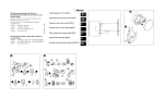
Fig. 1/Abb.1
3
I
F
E
GB
Fig. 2/Abb.2
Fig. 3/Abb. 3
4
D
NL
I
F
E
GB
D
NL
Fig. 4/Abb. 4
TX
F
RX
N
F
F
N
TX
N
N
RX
N
F
Fig. 5/Abb. 5
F
TX
RX
RX
TX
Fig. 6/Abb. 6
5
I
CARATTERISTICHE
VEDO180, è una fotocellula di ridotte dimensioni di semplice e veloce
installazione. Internamente è possibile regolare il fascio all'infrarosso di
oltre 180° in senso orizzontale in modo da poterla posizionare anche in
punti che sarebbero impossibili per le normali fotocellule. Inoltre la
particolare lente autocentrante corregge eventuali errori di alcuni gradi
anche in senso verticale.
L'alimentazione può essere a 12 o 24V sia in continua che in alternata.
VEDO180 è dotata anche della funzione di sincronismo per installazioni a
doppia coppia fotocellule (vedi capitolo “sincronismo”)
DATI TECNICI
Portata
Alimentazione
Consumo Rx (24 Vac)
Consumo Tx (24 Vac)
Corrente max contatti relé
Tensione max contatti relé
Temperatura funzionamento
Grado di protezione
Larghezza
Lunghezza
Altezza
m
Vac/Vdc
mA
mA
A
Vdc
°C
IP
mm
mm
mm
25*
12/24±10%
40
50
1
30
-10+70
44
44
102
34
* La portata è strettamente subordinata alle condizioni ambientali esterne. In presenza di nebbia, polvere o pioggia, la portata può ridursi anche del 70%.
6
I
DESCRIZIONE DELLE PARTI
Fig.1
1. Selezione alimentazione
2. Morsettiera collegamenti ricevitore
1 e 2 alimentazione
. 3 e 4 contatto normalmente chiuso (N.C.)
3. Morsettiera collegamenti trasmettitore
1 e 2 alimentazione
4. Fori di fissaggio
5. Ponticello sincronismo
6. Led acceso in presenza alimentazione sul trasmettitore
7. Led acceso quando il trasmettitore e ricevitore non sono allineati
8. Viti di fissaggio corpo interno
9 Entrata cavi
7
I
INSTALLAZIONE
Togliere il coperchio delle fotocellule aiutandosi con un cacciavite come
indicato in fig.3
Posizionare trasmettitore e ricevitore in asse tra loro e fissare la base
plastica con almeno 2 viti nei fori di fissaggio
(part. 4 Fig. 1).
Effettuare i collegamenti elettrici sulle morsettiere seguendo la figura 1.
Accertarsi di selezionare l'esatta alimentazione mediante il ponticello
(part. 1 di Fig. 1).
Il contatto della fotocellula ricevitore quando è alimentata e allineata con il
trasmettitore è normalmente chiuso (N.C.). Se necessitasse il contatto
normalmente aperto (N.O.) togliere l'elettronica dal supporto plastico,
tagliate la pistaAed eseguire la saldatura B come indicato in figura 4.
Per avere un buon funzionamento della fotocellula bisogna evitare di
installare il ricevitore nelle immediate vicinanze di fari d'illuminazione o in
prossimità di controlli elettronici a Triac o altre fonti di disturbo elettrico.
CENTRATURA OTTICA
Le fotocellule VEDO180 sono orientabili di oltre 180° in senso orizzontale.
Allentare leggermente le viti di fissaggio 8 delle figure 1 e 2, ruotare i
corpi interni delle fotocellule sino a quando non si allineano, quindi richiudere delicatamente le viti.
A fotocellule allineate il led rosso del ricevitore (part. 7 di fig 1) si spegne.
Leggere differenze di centratura in senso verticale vengono compensate da un sistema a lente autocentrante.
8
I
SINCRONISMO
Negli impianti con due coppie di fotocellule molto vicine, i raggi di una
coppia di fotocellule potrebbero interferire sull'altra causando dei mal
funzionamenti; a questo scopo, se è disponibile l'alimentazione
alternata, è consigliabile attivare il sincronismo.
Per attivare il sincronismo tagliare i ponticelli in entrambi i trasmettitori
(part. 5 di fig. 1) ed invertire l'alimentazione su una coppia di fotocellule,
vedi figura 5. Nel caso non sia possibile attivare il sincronismo bisogna
evitare di sistemare i due ricevitori su uno stesso lato e i trasmettitori
sull'altro, ma alternare ricevitore con trasmettitore, fig.6.
RACCOMANDAZIONI FINALI
Effettuare i cablaggi o modifiche ai collegamenti non prima di aver tolto
l'alimentazione.
La non osservanza delle suddette istruzioni, può pregiudicare il buon
funzionamento delle apparecchiature.
La ditta TELCOMA declina ogni responsabilità per eventuali
malfunzionamenti e/o danni dovuti derivanti dalla loro inosservanza.
La ditta TELCOMA srl si riserva la facoltà insindacabile di apportare, in
qualsiasi momento, le modifiche che si rendessero necessarie ai fini di un
miglioramento estetico e/o funzionale del prodotto.
9
I
GARANZIA
La presente garanzia copre gli eventuali guasti e/o anomalie dovuti a
difetti e/o vizi di fabbricazione.
La garanzia decade automaticamente in caso di manomissione o errato
utilizzo del prodotto.
Durante il periodo di garanzia la ditta TELCOMA srl si impegna a riparare
e/o sostituire le parti difettate e non manomesse. Restano a intero ed
esclusivo carico del cliente il diritto di chiamata, nonchè le spese di
rimozione, imballo e trasporto del prodotto per la riparazione o la
sostituzione.
SMALTIMENTO
Questo prodotto è formato da vari componenti che potrebbero a loro volta contenere sostanze inquinanti.
Non disperdere nell'ambiente!
Informarsi sul sistema di riciclaggio o smaltimento del prodotto attenendosi alle norme di legge vigenti a livello locale.
DICHIARAZIONE CE
Il sottoscritto Augusto Silvio Brunello, legale rappresentante della ditta
TELCOMA S.r.l., dichiara che il prodotto VEDO180 impiegato come fotocellula per apricancello: è conforme ai requisiti essenziali Direttiva 89/336
(EMC: EN 61000-6-3 + EN 61000-6-1) e Direttiva 73/23 (LVD: EN 60335-1)
e successive modifiche, se impiegato per gli usi preposti.
Il prodotto sopra indicato si intende parte integrante di una delle configurazioni di installazione tipiche, come riportato nei nostri cataloghi generali.
Conegliano, 05/06/2006
10
FI
CARACTÉRISTIQUES
VEDO180, est une photocellule de dimensions réduites, simple et rapide
à installer. À l'intérieur, il est possible de régler le faisceau à infrarouge de
plus de 180° dans le sens horizontal de manière à pouvoir la positionner à
des endroits ne permettant pas le fonctionnement de photocellules
ordinaires. De plus, la lentille particulière autocentrante corrige les
éventuelles erreurs de quelques degrés aussi dans le sens vertical.
Elle peut être alimentée à 12 ou à 24 V aussi bien en courant continu
qu'en courant alternatif. VEDO180 possède également la fonction de
synchronisation pour les installations avec deux paires de photocellules
(voir chapitre « synchronisation »)
DONNÉES TECHNIQUES
Portée
Alimentation
Consommation Rx (24 Vca
Consommation Tx (24 Vca)
Courant max. contacts relais
Tension max. contacts relais
Température de fonctionnement
Indice de protection
Largeur
Longueur
Hauteur
m
Vca/Vcc
mA
mA
A
Vcc
°C
IP
mm
mm
mm
25*
12/24±10%
40
50
1
30
-10+70
44
44
102
34
* La portée est étroitement liée aux conditions ambiantes extérieures.
En présence de brouillard, poussière ou pluie, la portée peut arriver à
se réduire de 70%.
11
F
DESCRIPTION DES PARTIES
Fig.1
1. Sélection alimentation
2. Bornier connexions récepteur
1 et 2 alimentation
3 et 4 contact normalement fermé (N.F.)
3. Bornier connexion émetteur
1 et 2 alimentation
4. Trous de fixation
5. Cavalier synchronisation
6. Led allumée en présence d'alimentation sur l'émetteur
7. Led allumée quand l'émetteur et le récepteur ne sont pas alignés
8. Vis de fixation corps interne
9. Entrée câbles
12
F
INSTALLATION
Enlever le couvercle des photocellules en s'aidant d'un tournevis comme
l'indique la fig.3.
Positionner l'émetteur et le récepteur dans le même axe et fixer la base
plastique avec au moins 2 vis dans les trous de fixation
(détail 4 Fig. 1).
Effectuer les connexions électriques sur les borniers suivant les
indications de la figure 1.
Contrôler de sélectionner l'alimentation exacte à l'aide du cavalier (détail
1 Fig. 1).
Le contact de la photocellule récepteur quand elle est alimentée et
alignée avec l'émetteur est normalement fermé (N.F.). Si l'on souhaite
avoir le contact normalement ouvert (N.O.) enlever l'électronique du
support plastique et couper la piste A puis effectuer la soudure B comme
l'indique la figure 4.
Pour avoir un bon fonctionnement de la photocellule, il faut éviter
d'installer le récepteur à proximité immédiate de projecteurs d'éclairage
ou de contrôles électroniques à Triac ou d'autres sources de parasites
électriques.
CENTRAGE OPTIQUE
Les photocellules VEDO180 sont orientables de plus de 180° dans le
sens horizontal.
Desserrer légèrement les vis de fixation 8 des figures 1 et 2, tourner les
corps internes des photocellules jusqu'à ce qu'ils s'alignent, puis resserrer délicatement les vis.
Quand les photocellules sont alignées, la led rouge du récepteur (détail
7 fig. 1) s'éteint.
De légères différences de centrage dans le sens vertical sont compensées par un système à lentille autocentrante.
13
F
SYNCHRONISATION
Dans les installations avec deux paires de photocellules très proches, les
rayons d'une paire de photocellules pourraient interférer sur l'autre en
causant des problèmes de fonctionnement ; dans ce cas, si
l'alimentation en courant alternatif est disponible, il est conseillé
d'activer la synchronisation.
Pour activer la synchronisation éliminer les cavaliers dans les deux
émetteurs (détail 5 fig. 1) et inverser l'alimentation sur une paire de
photocellules, voir figure 5. S'il n'est pas possible d'activer la
synchronisation, il faut éviter de placer les deux récepteurs sur le même
côté et les émetteurs de l'autre et alterner un récepteur avec un émetteur,
fig.6.
RECOMMANDATIONS FINALES
N'effectuer les câblages ou les modifications des raccordements
qu'après avoir coupé l'alimentation.
Le non-respect de ces instructions peut altérer le bon fonctionnement des
appareils.
La société TELCOMA décline toute responsabilité en cas d'éventuels
fonctionnements défectueux et/ou de dommages dérivant de leur
inobservation.
La société TELCOMA S.r.l. se réserve la faculté, de plein droit, d'apporter
à tout moment les modifications nécessaires en vue d'une amélioration
esthétique et/ou fonctionnelle du produit.
14
F
GARANTIE
La présente garantie couvre les pannes et/ou les anomalies éventuelles
dues à des défauts et/ou vices de fabrication.
La garantie cesse automatiquement en cas de modification ou
d'utilisation incorrecte du produit.
Durant la période de garantie, la société TELCOMA S.r.l. s'engage à
réparer et/ou à remplacer les parties défectueuses et non modifiées. Le
droit d'appel, ainsi que les frais de retrait, d'emballage et de transport du
produit pour la réparation ou le remplacement restent entièrement et
exclusivement à la charge du client.
MISE AU REBUT
Ce produit est constitué de divers composants qui pourraient à leur tour
contenir des substances polluantes.
Ne pas jeter dans la nature ! S'informer sur le système
de recyclage ou de mise au rebut du produit en respectant
les normes locales en vigueur.
DÉCLARATIONS CE
Je, soussigné Augusto Silvio Brunello, représentant légal de la société
TELCOMA S.r.l., déclare que le produit VEDO180 utilisé comme photocellule pour automatisme de portail: est conforme aux exigences essentielles de la Directive 89/336 (EMC: EN 61000-6-3 + EN 61000-6-1) et
de la Directive 73/23 (LVD: EN 60335-1) et modifications successives,
s'il est employé pour les utilisations prévues.
Le produit susmentionné s'entend partie intégrante d'une des configurations d'installation typiques, comme l'indiquent nos catalogues généraux.
Conegliano, 05/06/2006
15
E
CARACTERÍSTICAS
VEDO180 es una fotocélula de dimensiones reducidas, fácil y rápida de
instalar. En su interior es posible regular el haz de infrarrojo a más de
180° en el sentido horizontal, para poderla colocar también en puntos
que sería imposible para las fotocélulas normales. La lente
autocentradora especial corrige posibles errores de algunos grados,
incluso en el sentido vertical.
La alimentación puede ser de 12 ó 24V, tanto continua como alterna.
VEDO180 está dotada de la función de sincronización para instalaciones
de dos pares de fotocélulas (véase el capítulo “sincronización”)
DATOS TÉCNICOS
Alcance
Alimentación
Consumo receptora (24 Vac)
Consumo transmisora (24 Vac)
Corriente máx. contactos relé
Tensión máx. contactos relé
Temperatura de funcionamiento
Grado de protección
Anchura
Longitud
Altura
m
25*
Vac/Vdc 12/24±10%
mA
40
mA
50
A
1
Vdc
30
°C
-10+70
IP
44
mm
44
mm
102
mm
34
* El alcance depende de las condiciones ambientales exteriores. Ante la
presencia de niebla, polvo o lluvia, el alcance puede disminuir un 70%.
16
E
DESCRIPCIÓN DE LAS PARTES
Fig.1
1. Selección alimentación
2. Regleta conexiones receptora 1 y 2 alimentación
3 y 4 contacto normalmente cerrado (N.C.)
3. Regleta conexiones transmisora 1 y 2 alimentación
4. Orificios de fijación
5. Puente de sincronización
6. Led encendido con alimentación activa en la transmisora
7. Led encendido cuando la transmisora y receptora están
desalineadas
8. Tornillos de fijación cuerpo interior
9. Entrada de cables
17
E
INSTALACIÓN
Quite la tapa de las fotocélulas utilizando un destornillador, tal como indicado en la fig.3
Coloque la transmisora y la receptora alineadas entre sí y fije la base
de plástico con 2 tornillos en los orificios de fijación (det. 4 Fig. 1).
Efectúe las conexiones eléctricas en las regletas, respetando los pasos de la figura 1.
Asegúrese de seleccionar la alimentación exacta mediante el puente
(det. 1 de Fig. 1).
El contacto de la fotocélula receptora, cuando está alimentada y alineada con la transmisora, está normalmente cerrado (N.C.). Si fuera necesario el contacto normalmente abierto (N.A.) quite la electrónica del
soporte de plástico, corte la pista A y realice la soldadura B, tal como
indicado en la figura 4.
Para que la fotocélula funcione correctamente, no hay que instalar la
receptora cerca de faros de iluminación o cerca de controles electrónicos con Triac, u otras fuentes de perturbación eléctrica.
CENTRADO ÓPTICO
Las fotocélulas VEDO180 pueden orientarse a más de 180° en sentido
horizontal.
Afloje ligeramente los tornillos de fijación 8 de las figuras 1 y 2, gire los
cuerpos internos de las fotocélulas hasta que se aflojen; apriete
delicadamente los tornillos.
Con las fotocélulas alineadas, el led rojo de la receptora (det. 7 de fig 1)
se apaga.
Diferencias ligeras de centrado en sentido vertical son compensadas por
un sistema de lente autocentradora.
18
E
SINCRONIZACIÓN
En las instalaciones con dos pares de fotocélulas muy cercanas, los
rayos de un par de fotocélulas podrían interferir sobre el otro, provocando
un funcionamiento incorrecto; a tal fin, si está disponible la
alimentación alterna, se aconseja activar la sincronización.
Para activar la sincronización, corte los puentes de ambas transmisoras
(det. 5 de fig. 1) e invierta la alimentación en un par de fotocélulas, véase
la figura 5. Si no fuera posible activar la sincronización, no hay que
colocar las dos receptoras en un mismo lado ni las transmisoras en el
otro, sino que hay que alternar una receptora con una transmisora, fig.6.
RECOMENDACIONES FINALES
No efectúe el cableado ni las modificaciones a las conexiones sin haber
cortado la alimentación.
La inobservancia de dichas instrucciones puede afectar el
funcionamiento correcto de los equipos.
TELCOMA no se asume ninguna responsabilidad por posibles
problemas de funcionamiento o daños causados por su inobservancia.
TELCOMA S.r.l. se reserva el derecho de efectuar las modificaciones
que considere necesario en cualquier momento, a fin de mejorar estética
y funcionalmente sus productos.
19
E
GARANTÍA
La presente garantía cubre las averías o anomalías provocadas por defectos o vicios de fabricación.
La garantía pierde automáticamente validez en el caso de modificaciones o uso incorrecto del producto.
Durante el período de garantía, TELCOMA S.r.l. se obliga a reparar o
sustituir las piezas defectuosas y que no hayan sido modificadas.
Quedan a cargo del cliente el derecho de llamada y los gastos de desmontaje, embalaje y transporte del producto para su reparación o sustitución.
ELIMINACIÓN
Este producto está formado de varios componentes que, a su vez, podrían contener sustancias contaminantes.
¡No los abandone en el medio ambiente!
Infórmese sobre el sistema de reciclaje o eliminación del
producto, respetando las normas vigentes locales.
DECLARACIÓN DE CONFORMIDAD CE
El suscripto, Augusto Silvio Brunello, Representante legal de la firma
TELCOMA S.r.l., declara que el producto VEDO180 utilizado como fotocélula para dispositivos para abrir cancelas: responde a los requisitos
esenciales de la Directiva 89/336 (CEM: EN 61000-6-3 y EN 61000-61) y Directiva 73/23 (LVD: EN 60335-1) y siguientes actualizaciones, si
es utilizado para los usos previstos.
El producto antedicho forma parte integrante de una de las configuraciones
típicas de instalación, tal como indicado en nuestros catálogos generales.
Conegliano, 05/06/2006
20
GB
CHARACTERISTICS
VEDO 180 is a quick and easy to install small sized photocell.
Internally the infrared range can be horizontally adjusted to over 180°
so that it can be positioned in places that normal photocells could
never be positioned. Furthermore, the self-centring lenses also correct
possible vertical errors of a few degrees.
The power supply can be either 12V or 24V ac or dc. VEDO180 also
has the synchronism function for the installation of two photocell pairs
(see chapter “synchronism”).
TECHNICAL SPECIFICATIONS
Range
Power supply
Consumption Rx (24 Vac)
Consumption Tx (24 Vac)
Relay contacts max. current
Relay contacts max. voltage
Operating temperature
Protection class
Width
Length
Height
m
25*
Vac/Vdc 12/24±10%
mA
40
mA
50
A
1
Vdc
30
°C
-10+70
IP
44
mm
44
mm
102
mm
34
* The range is subject to the external environmental conditions. The
range can therefore be reduced by 70% in the presence of fog, dust or
rain.
21
GB
PARTS DESCRIPTION
Fig. 1
1. power supply selector
2. Receiver connection terminal block 1 and 2 power supply
3 and 4 normally closed contact (N.C.)
3. Transmitter connection terminal block 1 and 2 power supply
4. Fixing holes
5. Synchronism jumper
6. Led on when transmitter is powered
7. Led on when the transmitter and receiver are out of alignment
8. Internal casing fixing screws
9. Cable entrance
22
GB
INSTALLATION
Remove the photocell cover with a screwdriver as shown in fig. 3.
Position the transmitter and receiver in line with each other and fix the
plastic base with at least 2 screws through the fixing holes (detail 4 Fig. 1).
Following fig. 1, make the electrical connection on the terminal block.
Make sure that the correct power supply is selected by means of the
jumper (detail 1 Fig. 1).
The contact of the receiver photocell is normally closed (N.C.) when
powered and aligned with the transmitter.
If the contact needs to be normally open (N.O.), remove the electronics
from the plastic support and cut track A and carry out welding B as shown
in figure 4.
In order for the photocell to work correctly, avoid installing the receiver
close to spotlights, Triac electronic controls or other sources of electric
disturbance.
OPTIC ALIGNMENT
The VEDO180 photocells can be horizontally adjusted to over 180°.
Slacken screw 8 in figures 1 and 2, rotate the internal parts of the
photocells until they are out of alignment, then carefully tighten the
screws.
The red led of the receiver (detail 7 fig. 1) is off when the photocells are
aligned.
Slight vertical alignment differences are compensated by a self-centring
lens system.
23
GB
SYNCHRONISM
The beams from a pair of photocell in a system with two pairs of photocells that are close together could interfere on the other pair causing
malfunction; in this case it is advised to activate the synchronism if an
alternating power supply is available.
To activate the synchronism, cut the jumpers in both transmitters (detail 5 fig. 1) and invert the power supply on one of the photocell pairs,
see figure 5. If it is not possible to activate the synchronism, then avoid
positioning the two receivers on the same side and the transmitters on
the other, and alternate the receivers and transmitters, fig. 6.
FINAL ADVICE
Do not perform any wiring or modifications to the connections prior to
having isolated the power supply.
The non-observance of the said instructions could prejudice the correct
function of the equipment.
TELCOMA decline any responsibility for possible malfunction and/or damage due to their non-observance.
TELCOMA srl reserve the right to make modifications at any time they
deem necessary in order to improve the aesthetical and/or functional
aspect of the product.
24
GB
GUARANTEE
The present guarantee covers possible faults and/or irregularities due to
manufacturing defects and/or faults.
The guarantee will automatically expire in the event of tampering or
misuse of the product.
During the guarantee period TELCOMA srl pledge to repair and/or
replace defective and non-tampered parts. The call charges, as well as
the collection, packaging and transportation costs of the product for repair
or replacement are at the clients full and exclusive expense.
DISPOSAL
This product is made up of various parts that could contain polluting
substances.
Avoid release to the environment!
Enquire about the local recycling or disposal systems in
compliance with present laws and regulations.
EC DECLARATION
The undersigned, Augusto Silvio Brunello, legal representative of
TELCOMA S.r.l., declares that the product VEDO180 used as a gate
automation photocell: Is in accordance with the essential requirement
of Directive 89/336 (EMC: EN 61000-6-3 + EN 61000-6-1) and
Directive 73/23 (LVD: EN 60335-1) and subsequent modifications, if
implemented for the said use.
The above mentioned product is an integral part of the typical installation
configurations as illustrated in our general catalogue.
Conegliano, 05/06/2006
25
D
MERKMALE
VEDO180 ist eine relativ kleine Fotozelle, die einfach und schnell installiert werden kann. Ihr Infrarotstrahl kann von innen um mehr als
180° horizontal verstellt werden, so dass ihre Installation auch an
Stellen möglich ist, wo normale Fotozellen nicht angewendet werden
können. Weiterhin berichtigt die selbstzentrierende Linse eventuelle
Fehler auch in vertikaler Richtung um mehrere Grade.
Die Versorgung kann sowohl in Gleichspannung als auch in
Wechselspannung 12 oder 24V sein. VEDO180 ist auch mit der
Synchro-Funktion für die Installation von zwei Fotozellenpaaren ausgestattet (siehe Kap. “Synchronismus”)
TECHNISCHE DATEN
Reichweite
Versorgung
Verbrauch Rx (24 Vac)
Verbrauch Tx (24 Vac)
Höchststrom, Relaiskontakte
Höchstspannung, Relaiskontakte
Betriebstemperatur
Schutzart
Breite
Länge
Höhe
m
Vac/Vdc
mA
mA
A
Vdc
°C
IP
mm
mm
mm
25*
12/24±10%
40
50
1
30
-10+70
44
44
102
34
* Die Reichweite hängt stark von den Bedingungen der
Außenumgebung ab und kann sich bei Nebel, Staub oder Regen um
sogar 70% verringern.
26
D
BESCHREIBUNG DER BESTANDTEILE
Abb.1
1. Auswahl der Versorgung
2. Klemmleiste Empfängeranschlüsse
1 und 2 Versorgung
3 und 4 gewöhnlich geschlossener Kontakt (NC-Kontakt)
3. Klemmleiste für Senderanschlüsse
1 und 2 Versorgung
4. Befestigungslöcher
5. Synchronismus-Überbrückung
6. Led eingeschaltet bei Vorhandensein der Versorgung am Sender
7. Led eingeschaltet, wenn Sender und Empfänger nicht gefluchtet sind
8. Schrauben zur Befestigung des Innenkörpers
9. Kabeleingang
27
D
INSTALLATION
Den Deckel mit Hilfe eines Schraubenziehers von den Fotozellen nehmen – siehe Abb. 3
Sender und Empfänger untereinander auf derselben Achse anbringen
und die Plastikbasis mit mindestens 2 Schrauben in den
Befestigungslöchern festschrauben (Detail 4, Abb. 1).
Die elektrischen Anschlüsse an den Klemmleisten gemäß Abbildung 1
ausführen.
Sicher stellen, dass die korrekte Versorgung mittels Überbrückung
gewählt ist (Detail 1, Abb. 1).
Der Kontakt des Empfängerteils der Fotozelle ist gewöhnlich geschlossen (NC-Kontakt), wenn der Empfänger gespeist und mit dem Sender
gefluchtet ist. Sollte ein gewöhnlich geöffneter Kontakt (NO-Kontakt) erforderlich sein, die Elektronik von der Plastikhalterung nehmen, die
Bahn A durchschneiden und die Schweißung B wie in Abbildung 4 gezeigt ausführen.
Damit die Fotozelle korrekt funktioniert, sollte der Empfänger nicht in
der unmittelbaren Nähe einer Beleuchtung oder elektronischer TriacSteuervorrichtungen oder sonstiger elektrischer Störungsquellen installiert werden.
ZENTRIEREN DES STRAHLS
Die Fotozellen VEDO180 können horizontal um mehr als 180° verstellt
werden.
Die Befestigungsschrauben 8 in den Abbildungen 1 und 2 leicht lösen
und die Innenkörper der Fotozellen drehen, bis sie gefluchtet sind,
dann die Schrauben behutsam festziehen.
Die rote LED am Empfänger (Detail 7, Abb. 1) schaltet aus, nachdem
die Fotozellen gefluchtet sind.
Geringfügige vertikale Zentrierungsfehler werden durch die selbstzentrierende Linse ausgeglichen.
28
D
SYNCHRONISMUS
In Anlagen mit zwei sehr nah angebrachten Fotozellenpaaren könnten
die Strahlen des einen Fotozellenpaars mit jenen des anderen
interferieren und Betriebsstörungen verursachen. Um dies zu vermeiden,
kann - falls die Versorgung mit Wechselspannung erfolgt - die
Synchro-Funktion aktiviert werden.
Zur Aktivierung des Synchronismus, die Überbrückungen an beiden
Sendern durchschneiden (Detail 5, Abb. 1) und die Versorgung an
einem Fotozellenpaar umkehren - siehe Abbildung 5. Falls die SynchroFunktion nicht aktiviert werden kann, dürfen die beiden Empfänger auf
derselben Seite und die Sender auf der anderen nicht angebracht
werden, sondern Empfänger und Sender sind abwechselnd zu
installieren – sieheAbb. 6.
ABSCHLIEßENDE HINWEISE
Verdrahtungen oder Änderungen an den Anschlüssen dürfen erst nach
Abschaltung der Versorgung ausgeführt werden.
Die Nichtbeachtung der obigen Anweisungen kann den korrekten Betrieb
derApparaturen beeinträchtigen.
Die Firma TELCOMA übernimmt keinerlei Haftung für eventuelle
Betriebsstörungen und/oder Schäden infolge der Nichtbeachtung der
Anweisungen.
Die Firma TELCOMA srl behält es sich vor, nach ihrem unanfechtbaren
Urteil jederzeit Änderungen anzubringen, die für eine ästhetische
und/oder funktionelle Verbesserung des Produktes notwendig sein
sollten.
29
D
GARANTIE
Die vorliegende Garantie deckt eventuelle Mängel und/oder Störungen
aufgrund von Fabrikationsfehlern.
Die Garantie wird im Fall von Handhabung oder falscher Benutzung
des Produktes automatisch ungültig.
Die Firma TELCOMA srl verpflichtet sich während der Garantiezeit, defekte und nicht gehandhabte Teile zu reparieren und/oder zu ersetzen.
Voll und ausschließlich zu Lasten des Kunden gehen die Rufgebühr sowie die Kosten für Entfernung, Verpackung und Beförderung des
Produktes für die Reparatur bzw. den Ersatz.
Damit die Fotozelle korrekt funktioniert, sollte der Empfänger nicht in
der unmittelbaren Nähe einer Beleuchtung oder elektronischer TriacSteuervorrichtungen oder sonstiger elektrischer Störungsquellen installiert werden.
ENTSORGUNG
Dieses Produkt besteht aus verschiedenen Komponenten, die
Schadstoffe enthalten könnten.
Nicht in die Umwelt geben! Informieren Sie sich, wie
Sie das Produkt wiederverwerten oder entsorgen können
und halten Sie sich an die örtlich gültigen Vorschriften.
CE-ERKLÄRUNG
Der Unterzeichnete Augusto Silvio Brunello, Gesetzlicher Vertreter der
Firma TELCOMA S.r.l., erklärt, dass das Produkt VEDO180, eingesetzt
als Fotozelle für Toröffner: mit den wichtigsten Anforderungen der
Richtlinie 89/336 (EMC: EN 61000-6-3 + EN 61000-6-1) und der
Richtlinie 73/23 (LVD: EN 60335-1) und späteren Änderungen konform
ist, falls für den vorgesehenen Zweck eingesetzt.
Das oben genannte Produkt ist Bestandteil einer der typischen
Anlagenkonfigurationen, so wie in unseren Generalkatalogen angegeben.
Conegliano, 05/06/2006
30
NL
KENMERKEN
VEDO180, is een compacte fotocel die snel en eenvoudig geïnstalleerd
kan worden. Het is mogelijk de infraroodbundel binnenin over ruim 180°
in het horizontale vlak af te stellen zodat de fotocel ook daar aangebracht
kan worden waar dat voor normale fotocellen onmogelijk zou zijn.
Bovendien corrigeert de speciale zelfcentrerende lens ook in het verticale
vlak eventuele fouten van enkele graden.
De stroomvoorziening van de fotocel kan plaatsvinden op 12 of 24V,
zowel gelijkstroom als wisselstroom. VEDO180 is ook voorzien van een
synchronisatiefunctie voor installaties met een dubbel stel fotocellen (zie
hoofdstuk “synchronisme”)
TECHNISCHE GEGEVENS
Bereik
Stroomvoorziening
Verbruik Rx (24 Vac)
Verbruik Tx (24 Vac)
Max. stroom contacten relais
Max. spanning contacten relais
Werkingstemperatuur
Beschermingsklasse
Breedte
Lengte
Hoogte
m
Vac/Vdc
mA
mA
A
Vdc
°C
IP
mm
mm
mm
25*
12/24±10%
40
50
1
30
-10+70
44
44
102
34
* Het bereik is sterk afhankelijk van weersinvloeden en ander
omstandigheden buiten. In geval van mist, stof of regen kan het bereik
dan ook met 70% afnemen.
31
NL
BESCHRIJVING VAN DE ONDERDELEN
afb.1
1. Selectie stroomvoorziening
2. Klemmenstrip aansluitingen ontvanger
1 en 2 stroomvoorziening
3 en 4 contact normaal dicht (N.C.)
3. Klemmenstrip aansluitingen zender
1 en 2 stroomvoorziening
4. Boringen voor bevestiging
5. Bruggetje synchronisme
6. Led brandt bij spanning op de zender
7. Led brandt wanneer zender en ontvanger niet uitgelijnd zijn
8. Bevestigingsschroeven intern gedeelte
9. Ingang voor kabels
32
NL
INSTALLATIE
Haal met behulp van een schroevendraaier het dekplaatje van de
fotocellen af, zoals dat op afb.3 is aangegeven
Plaats zender en ontvanger op één lijn en bevestig de plastic basis met
tenminste 2 schroeven in de bevestigingsboringen (onderdeel 4 afb. 1).
Voer de elektrische aansluitingen op de klemmenstrips volgens
afbeelding 1 uit.
Zorg ervoor de juiste stroomvoorziening te selecteren het bruggetje
(onderdeel 1 van afb. 1).
Het contact van de fotocel ontvanger is, wanneer het onder spanning
staat en met de zender uitgelijnd is, normaal dicht (N.C.). Mocht het nodig
zijn dat het contact normaal open (N.O.) is, dan dient u de elektronica van
de plastic steun te halen, het kanaaltje A te verbreken en de soldering B
uit te voeren zoals dat op afbeelding 4 is aangegeven.
Voor een goede werking van de fotocel mag u de ontvanger niet in de
onmiddellijke nabijheid van schijnwerpers plaatsen of vlakbij
elektronische aansturingen op Triac of andere elektrische
storingsbronnen.
OPTISCHE CENTRERING
De fotocellen VEDO180 kunt u over meer dan 180° in het horizontale vlak
richten.
Draai de bevestigingsschroeven 8 van de afbeeldingen 1 en 2 enigszins
los, draai de interne delen van de fotocellen totdat ze op één lijn liggen en
draai daarna de schroeven zachtjes vast.
Wanneer de fotocellen uitgelijnd zijn, gaat het rode ledlampje van de
ontvanger (onderdeel 7 van afb. 1) uit.
Geringe verschillen in centrering in het verticale vlak worden
gecompenseerd door een systeem met zelfcentrerende lens.
33
NL
SYNCHRONISME
Bij installaties waarbij twee stel fotocellen heel dichtbij elkaar geplaatst
zijn, zouden de stralen van het ene stel fotocellen het andere kunnen
beïnvloeden waardoor er storingen zouden kunnen ontstaan; om dit te
voorkomen, verdient het aanbeveling het synchronisme te activeren indien er wisselstroom aanwezig is .
Om het synchronisme te activeren dient u in beide zenders de bruggetjes (onderdeel 5 van afb. 1) te verbreken en de stroomvoorziening op
één stel fotocellen om te draaien, zie afbeelding 5. Indien het niet mogelijk is het synchronisme te activeren, dient u ervoor te zorgen dat de
twee ontvangers niet aan één kant en de zenders op de andere kant
geplaatst worden, maar ontvanger en zender met elkaar af te wisselen,
afb.6.
SLOTBEPALINGEN
Sluit geen kabels aan en breng geen veranderingen in de aansluitingen aan voordat u de spanning van het systeem hebt gehaald.
Wanneer u de hierboven gegeven aanwijzingen niet in acht neemt, kan
dit tot gevolg hebben dat de apparatuur niet goed werkt.
De firma TELCOMA wijst elke aansprakelijkheid van de hand voor
eventuele storingen en/of schade als gevolg van het feit dat de aanwijzingen niet in acht zijn genomen.
De firma TELCOMA srl behoudt zich het recht voor volgens haar definitief oordeel, op elk door haar gewenst moment, die wijzigingen aan te
brengen welke zij nodig acht in verband met een verbetering, qua uiterlijk dan wel qua functie van het product.
34
NL
GARANTIE
Deze garantie dekt eventuele storingen en/of abnormaliteiten die te
wijten zijn aan defecten en/of fabricagefouten.
De garantie komt automatisch te vervallen indien er veranderingen aan
het product zijn aangebracht of als dit verkeerd gebruikt is.
Tijdens de garantieperiode verplicht de firma TELCOMA srl zich defecte
onderdelen waaraan geen veranderingen zijn aangebracht, te repareren
en/of te herstellen. Voor rekening van de klant komt het voorrijrecht, als
ook de kosten voor verwijdering, verpakking en vervoer van het product
met betrekking tot reparatie of vervanging.
AFVALVERWERKING
Dit product bestaat uit verschillende onderdelen die op hun beurt
vervuilende stoffen zouden kunnen bevatten.
Laat ze niet in het milieu achter!
Win informatie in over systemen van recycling of
afvalverwerking voor dit product en houd u daarbij aan de
wettelijke bepalingen zoals die op de plaats van gebruik van kracht zijn.
EG-VERKLARING
Ondergetekende Augusto Silvio Brunello, Wettelijk vertegenwoordiger
van de firma TELCOMA S.r.l., verklaart dat het product VEDO180 bij
gebruik als fotocel voor een poortopener: in overeenstemming is met de
essentiële vereisten van Richtlijn 89/336 (EMC: EN 61000-6-3 + EN 610006-1) en Richtlijn 73/23 (LVD: EN 60335-1) en daaropvolgende wijzigingen,
indien gebruikt voor het doel waarvoor het bestemd is.
Het hierboven beschreven product vormt integrerend deel met een
van de typische installatieconfiguraties, zoals die in onze algemene
catalogi voorkomen.
Conegliano, 05/06/2006
35
I
DIMA PER IL FISSAGGIO
F PATRON POUR LE FIXAGE
E PATRON PARA FIJAR
GB PROFILE TO FIX
D PROFILUM ZUR BEFESTIGUNG
NL BOORMAL
Telcoma srl - Via L. Manzoni, 11 - Z.I. Campidui - 31015 Conegliano - (TV) Italy
Tel. +39 0438 451099 - Fax +39 0438 451102 - Part. IVA 00809520265
Http://www.telcoma.it E-mail:[email protected]