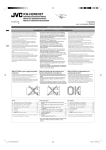
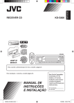
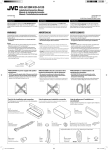
1
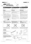
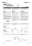
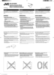
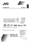
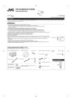
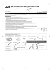
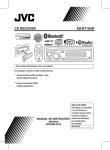
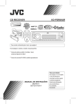
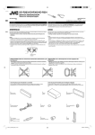
KD-S34
Installation/Connection Manual
Manual de instalación/conexión
0607DTSMDTJEIN
EN, SP
GET0518-002A
[J]
© 2007 Victor Company of Japan, Limited
ENGLISH
ESPAÑOL
PREPARATIONS
TROUBLESHOOTING
You need the installation kits which corresponds to your car.
• Mark all the check boxes (
) to make sure you have follow the instructions and the listed parts.
•
*
•
*
•
*
•
*
*
•
*
•
*
*
•
*
Check the battery system in your car
12 V DC, NEGATIVE ground
Prepare this before installation
The fuse blows.
Are the red and black leads connected correctly?
Power cannot be turned on.
Is the yellow lead connected?
No sound from the speakers.
Is the speaker output lead short-circuited?
Sound is distorted.
Is the speaker output lead grounded?
Are the “–” terminals of L and R speakers grounded in common?
Noise interfere with sounds.
Is the rear ground terminal connected to the car’s chassis using shorter and thicker cords?
This unit becomes hot.
Is the speaker output lead grounded?
Are the “–” terminals of L and R speakers grounded in common?
This unit does not work at all.
Have you reset your unit?
Parts list for installation and connection
A
B
C
D
Control panel
Sleeve
Trim plate
Power cord
E
F
G
H
I
J
K
Washer (ø5)
Lock nut (M5)
Mounting bolt—
M5 × 20 mm (M5 × 13/16")
Rubber cushion
Handles
Remote controller
Battery
INSTALLATION
If you are not sure how to install this unit correctly, consult your JVC car audio dealer.
In dash-mounting
Removing the unit
Before removing the unit, release the rear section.
When you stand the unit, be careful
not to damage the fuse on the rear.
Do the required electrical
connections.
Bend the appropriate tabs
to hold the sleeve firmly
in place.
When installing the unit without using the sleeve
When using the optional stay
In a Toyota car for example, first remove the car radio and install the unit in its place.
Fire wall
Stay (option)
Flat type screws
—M5 × 8 mm (M5 × 3/8")*
Dashboard
* Not supplied for this unit.
Bracket*
Screw (option)
Install the unit at an angle of
less than 30˚.
Pocket
Flat type screws
—M5 × 8 mm (M5 × 3/8")*
Bracket*
1
Install_EN_KD-S34[J]f.indd 1
6/12/07 8:46:32 AM
ELECTRICAL CONNECTIONS
Make sure to disconnect the battery’s negative terminal.
• Be sure to ground this unit to the car’s chassis again after installation.
High
Note:
It is recommended to connect to the speakers with maximum power of more than 50 W (both at the rear and at the front, with an impedance of 4 Ω to 8 Ω).
If the maximum power is less than 50 W, change “AMP GAIN” setting to prevent the speakers from being damaged (see page 14 of the INSTRUCTIONS).
Typical connections
Antenna terminal
Heat sink
Connecting the external amplifiers and/or subwoofer
Line out
To external
components
To metallic body or
chassis of the car
Yellow *2
White
Gray with black stripe
Front speakers
or
Set “L/O MODE” to “WOOFER”
(See page 14 of the INSTRUCTIONS.)
Fuse block
To an accessory terminal in
the fuse block
Remote lead
Remote lead
JVC Amplifier
JVC Amplifier
Blue with white
stripe
Green
Purple with black stripe
Rear speaker (right)
Red
Rear speakers
Gray
Green with black stripe
Rear speaker (left)
JVC Amplifier
To a live terminal in the
fuse block connecting to the
car battery (bypassing the
ignition switch) (constant
12 V)
White with black stripe
Front speaker (right)
To the remote lead of other equipment
or automatic antenna if any
Ignition switch
Connect only the front speakers if your
speaker system is two-speaker system.
Front speaker (left)
Remote lead (blue with white stripe)
Set “L/O MODE” to “REAR”
(See page 14 of the
INSTRUCTIONS.)
15 A fuse
Black
Y-connector *1
Remote lead
Rear ground terminal
To the remote lead of other
equipment or automatic antenna if
any (200 mA max.)
Orange with
white stripe
Front
speakers
Subwoofer
To car light control switch
Purple
PRECAUTIONS on power supply and speaker connections
*1 Not supplied for this unit.
*2 Before checking the operation of this unit prior to installation, this lead must be connected, otherwise power cannot be
turned on.
*3 Firmly attach the ground wire to the metallic body or to the chassis of the car—to the place not coated with paint (if
coated with paint, remove the paint before attaching the wire). Failure to do so may cause damage to the unit.
*4 Signal cord (not supplied for this unit).
Connecting the external components
(A) JVC CD changer, SIRIUS Satellite radio, XM Satellite radio, Apple iPod, or JVC D. player
Set “CHANGER” for the external input setting (See page14 of the INSTRUCTIONS.)
• For listening to the SIRIUS Satellite radio, connect a JVC DLP—Down Link Processor (separately purchased) to this unit.
• The iPod or D. player (separately purchased) can be connected using an interface adapter (not supplied)—KS-PD100
(for iPod) or KS-PD500 (for D. player).
CAUTION:
Before connecting the external components, make sure that the unit is turned off.
iPod is a trademark of Apple Inc., registered in the U.S. and other
countries.
CD changer jack
Connection 1 (integrated connection)
Connection 2 (alternative connection)
JVC DLP
JVC DLP
• For listening to the XM Satellite radio, you can also connect XMDirectTM Universal
Tuner Box (separately purchased) through this unit using JVC Smart Digital Adapter—
XMDJVC100 (not supplied).
or
XMDirect Universal Tuner Box
TM
Antenna (supplied
with XMDirectTM
Universal Tuner Box)
Apple iPod
or
or
JVC CD changer
JVC D. player
or
or
Apple iPod
JVC CD changer
or
XMDJVC100
JVC D. player
To JVC CD changer, KS-PD100, or KS-PD500 if using Connection 1
(intergrated connection)
*5 Signal cord supplied with your JVC CD changer or DLP.
(B) JVC PnP (Plug and Play)
(C) Other external component
Set “EXT IN” for the external input setting (See page14 of the INSTRUCTIONS.)
You can also connect an external component through this unit using Line Input Adapter, KS-U57 (not supplied) or AUX Input Adapter,
KS-U58 (not supplied).
You can also connect JVC PnP through this unit using JVC SIRIUS radio adapter, KS-U100K (not supplied).
• Turning on/off the unit can also turn on/off the JVC PnP.
Signal cord (not supplied for this unit)
External
component
To headphones jack
CD changer jack
Stereo mini plug
JVC PnP
CD changer jack
External
component
DC power plug
3.5 mm (3/16”) stereo
mini plug
To DC IN jack
2
Install_EN_KD-S34[J]f.indd 2
6/15/07 5:11:48 PM
KD-S34
Installation/Connection Manual
Manual de instalación/conexión
ESPAÑOL
PREPARATIVOS
LOCALIZACIÓN DE AVERIAS
Utilice los kits de instalación que correspondan a su vehículo.
• Marque todas las casillas ( ) para cerciorarse de que se han seguido las instrucciones, y de tener las piezas mencionadas.
• El fusible se quema.
* ¿Están los conductores rojo y negro correctamente conectados?
• No es posible conectar la alimentación.
* ¿Está el cable amarillo conectado?
• No sale sonido de los altavoces.
* ¿Está el cable de salida del altavoz cortocircuitado?
• El sonido presenta distorsión.
* ¿Está el cable de salida del altavoz conectado a masa?
* ¿Están los terminales “–” de los altavoces L y R conectados a una masa común?
• Perturbación de ruido.
* ¿El terminal de tierra trasero está conectado al chasis del automóvil utilizando los cordones más corto y más grueso?
• La unidad se calienta.
* ¿Está el cable de salida del altavoz conectado a masa?
* ¿Están los terminales “–” de los altavoces L y R conectados a una masa común?
• Este receptor no funciona en absoluto.
* ¿Reinicializó el receptor?
Verifique el sistema de batería de su vehículo
12 V CC, NEGATIVO a masa
Prepare esto antes de la instalación
Lista de piezas para instalación y conexión
A
B
C
D
Panel de control
Cubierta
Placa de guarnición
Cordón de
alimentación
E
F
G
H
I
J
K
Arandela (ø5)
Tuerca de
seguridad (M5)
Perno de montaje—
M5 × 20 mm (M5 × 13/16 pulgada)
Cojín de goma
Manijas
Control remoto
Pila
INSTALACION
Si usted no está seguro de cómo instalar correctamente la unidad, consulte con su concesionario de JVC de equipos de audio para automóviles.
Montaje en el tablero
Extracción de la unidad
Antes de extraer la unidad, libere la sección trasera.
Al poner la unidad vertical, tenga
cuidado de no dañar el fusible
provisto en la parte posterior.
Realice las conexiones eléctricas
requeridas.
Doble las lengüetas
apropiadas para retener
firmemente la manga en
su lugar.
Instalación de la unidad sin utilizar la cubierta
Cuando emplea un soporte opcional
Tabique a prueba
de incendios
En un Toyota por ejemplo, primero retire la radio del automóvil y luego instale la unidad en su lugar.
Soporte (opción)
* No suministrado con esta unidad.
Tornillos tipo plano—
M5 × 8 mm (M5 × 3/8 pulgada)*
Tablero de
instrumentos
Ménsula*
Tornillo (opción)
Instale la unidad a un ángulo
de menos de 30˚.
Compartimiento
Tornillos tipo plano—
M5 × 8 mm (M5 × 3/8 pulgada)*
Ménsula*
3
Install_SP_KD-S34[J]f.indd 3
12/6/07 9:08:08 am
CONEXIONES ELECTRICAS
Asegúrese de desconectar el terminal negativo de la batería.
• Asegúrese de volver a conectar a masa esta unidad al chasis del automóvil después de la instalación.
Alta
Nota:
Se recomienda conectar los altavoces con una potencia máxima de más de 50 W (tanto atrás como adelante, con una impedancia de 4 Ω a 8 Ω).
Si la potencia máxima es de menos de 50 W, cambie “AMP GAIN” para evitar daños en los altavoces (consulte la página 14 del MANUAL DE INSTRUCCIONES).
Conexiones tipicas
Sumidero térmico
Conexión de los amplificadores y/o subwoofer externos
Terminal de la antena Salida de línea
Fusible de 15 A
Negro
Amarillo *
Altavoz delantero
(izquierdo)
Interruptor de
encendido
A un cuerpo metálico o
chasis del automóvil
2
Blanco
A un terminal activo del
bloque de fusibles conectado
a la batería del automóvil
(desviando el interruptor de
encendido) (12 V constantes)
Altavoz delantero
(derecho)
Amplificador
de JVC
o
Ajuste “L/O MODE” a “WOOFER”
(Consulte la página 14 del MANUAL
DE INSTRUCCIONES.)
Bloque de
fusibles
A un terminal accesorio del
bloque de fusibles
Gris
Verde con rayas negras
Altavoz trasero
(izquierdo)
Azul con rayas
blancas
Verde
Púrpura con rayas negras
Subwoofer
Al conductor remoto de otro equipo o
de la antena automática, si hubiere
(máx. 200 mA)
Naranja con rayas
blancas
Al conductor remoto de otro equipo o de
la antena automática, si hubiere
Altavoces
traseros
Gris con rayas negras
Rojo
Cable remoto (azul con rayas blancas)
Ajuste “L/O MODE” a “REAR”
(Consulte la página 14 del
MANUAL DE INSTRUCCIONES.)
A los componentes
externos
Conecte solamente los altavoces
delanteros si su sistema del altavoz es
sistema del dos-altavoz.
Blanco con rayas negras
Conector en Y *1
Cable remoto
Terminal de tierra posterior
Altavoces delanteros
Cable remoto
Cable remoto
Amplificador
de JVC
Amplificador
de JVC
Altavoces
delanteros
Al interruptor de control de las
luces del automóvil
Altavoz trasero (derecho) Púrpura
PRECAUCIONES sobre las conexiones de la fuente de alimentación y de los altavoces
*1 No suministrado con esta unidad.
*2 Antes de comprobar el funcionamiento de esta unidad previa a de la instalación, es necesario conectar este cable, de lo
contrario no se podrá conectar la alimentación.
*3 Fije firmemente el cable de tierra a la carrocería metálica o al chasis—a un lugar no cubierto con pintura (si está cubierto
con pintura, quítela antes de fijar el cable). De lo contrario, se podrían producir daños en la unidad.
*4 Cable de señal (no suministrado con esta unidad).
Conexión de los componentes externos
(A) Cambiador de CD de JVC, radio satelital SIRIUS, radio satelital XM, iPod de Apple o reproductor JVC D.
Seleccione “CHANGER” para el ajuste de entrada externa (Consulte la página14 del MANUAL DE INSTRUCCIONES.)
• Para escuchar la radio satelital SIRIUS, conecte un DLP (Down Link Processor) de JVC (adquirido por separado) al receptor.
• Puede conectar el iPod o el reproductor D. (adquirido por separado) usando un adaptador de interfaz (no suministrado)
—KS-PD100 (para iPod) o KS-PD500 (para el reproductor D.).
PRECAUCION:
Antes de conectar los componentes externos, asegúrese de que la unidad esté apagada.
iPod es una marca comercial de Apple Inc., registrada en los
EE.UU. y otros países.
Jack para el cambiador de CD
Conexión 1 (conexión integrada)
Conexión 2 (conexión alternativa)
DLP JVC
DLP JVC
Apple iPod
o
Cambiador de CD
de JVC
o
o
• Para escuchar la radio satelital XM, también puede conectar el Sintonizador universal
XMDirect™ (adquirido por separado) al receptor mediante un adaptador Smart Digital
XMDJVC100 de JVC (no suministrado).
Reproductor D. JVC
o
Sintonizador universal XMDirect™
Antena (suministrada
con el Sintonizador
universal XMDirect™)
o
Cambiador de CD
de JVC
Apple iPod
o
XMDJVC100
Reproductor D. JVC
Al cambiador de CD de JVC, KS-PD100, o KS-PD500 si está usando la
Conexión 1 (conexión integrada)
*5 Cable de señal suministrado con su cambiador de CD o DLP JVC.
(B) PnP (“Plug and Play”) JVC
(C) Otro componente externo
Seleccione “EXT IN” para el ajuste de entrada externa (Consulte la página14 del MANUAL DE
INSTRUCCIONES.)
También puede conectar un componente externo a través de esta unidad, usando el adaptador de entrada de línea KS-U57 (no
suministrado), o el adaptador de entrada AUX, KS-U58 (no suministrado).
También podrá conectar la PnP JVC a través de este receptor utilizando el adaptador para radio SIRIUS JVC,
KS-U100K (no suministrado).
• Al encender/apagar el receptor también se enciende/apaga la PnP JVC.
Cable de señal (no suministrado con esta unidad)
Componente
exterior
Al jack para auriculares
Jack para el cambiador de CD
Miniclavija estéreo
Componente
exterior
PnP JVC
Jack para el cambiador de CD
Clavija de alimentación de CC
Miniclavija estéreo de
3,5 mm (3/16 pulgada)
Al jack DC IN
4
Install_SP_KD-S34[J]f.indd 4
12/6/07 9:08:17 am