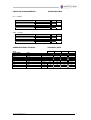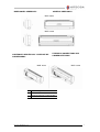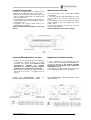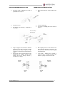
1
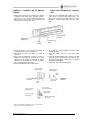
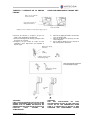
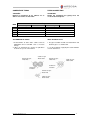
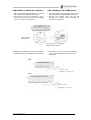
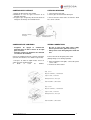
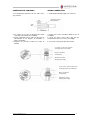
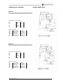
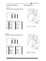
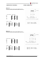
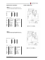
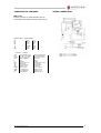
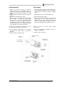
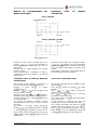
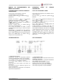
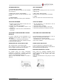
AGUA. TIPO PARED
WATER. WALL MOUNTED
FANCOILS UNITS
FPW
04.14 Ref.200344 Rev.101
20, 25, 35, 40
INSTALLATION, OPERATION AND MAINTENENANCE INSTRUCTIONS
INSTRUCIONES DE INSTALACIÓN, FUNCIONAMIENTO Y MANTENIMIENTO
UNIDADES FANCOILS
Gracias por confiar en el Producto Hitecsa.
Desde nuestra compañía llevamos más de 30
años ofreciendo al mercado una gama extensa
de equipamiento especializado para las
instalaciones de climatización y refrigeración.
Nuestro enfoque de búsqueda de soluciones
eficientes, flexibles, manejables y prácticas ha
constituido un sello característico de nuestro
catálogo de producto.
La versatilidad de nuestra fábrica nos permite
aportar soluciones casi personalizables a cada
proyecto, buscando una solución para cada
problema que surge en el día a día del diseño e
implantación de instalaciones de climatización.
Thank you for trust in Hitecsa Product. From our
company we are offering to the market, for more
than 30 years, an extended range of specialized
units for air conditioning and cooling
installations. Our approach is based in
efficiency, flexibility, manageability and practical
solutions. It has built a hallmark of our product
catalogue.
The versatility of our factory allows us to
contribute solutions almost customitzables in
each project, searching a solution for every
problem
that
arises
in
design
and
implementation of air conditioning installations.
04.14 Ref. 200344 Rev. 101
Desde todos los que componemos Hiplus Aire
Acondicionado, una vez más muchas gracias.
From Hiplus Aire Acondicionado’s team, once
more thank you very much
2
ÍNDICE
CONTENTS
Introducción .............................................................. 4
Introduction ......................................................... 4
Precauciones de seguridad ...................................... 4
Safety precautions ............................................... 4
Descripción de componentes .................................... 5
Components description ...................................... 5
Límites de funcionamiento ....................................... 6
Operation limits .................................................... 6
Características técnicas ........................................... 6
Technical data ..................................................... 6
Dimensiones generales ............................................ 7
General dimensions ............................................. 7
Conexiones hidráulicas y drenaje de condensados .. 7
Hidrúlic connections and condensate drain .......... 7
Lugar de instalación ................................................. 8
Installation location ............................................. 8
Instalación montaje de la placa ................................. 8
Mounting plate installation ................................... 8
Tuberías y drenaje de la unidad fancoil ....................10
Piping and drainge of fan coil unit ......................... 10
Conexión de tubos ...................................................12
Piping connection .................................................12
Como sacar el marco rejilla ......................................13
How to remove the fram grille ...............................13
Comprobar el drenaje ..............................................14
Checking drainage ...............................................14
Conexiones de cableado...........................................14
Wiring connections................................................14
Purgación aire ..........................................................21
Air purging ...........................................................21
Instalación marco de la rejilla en el fancoil ................22
Installing the grille frame on the fan coil ................ 22
Preparación mando a distancia.................................22
Preparation remote controller................................22
Uso del mando a distancia........................................23
Use of the remote controller ..................................23
Descripción y funciones del mando a distancia ........23
Descriptions and functions of remote controller.....23
Manual de funcionamiento del mando a distancia ...27
Operation guide of remote controller ..................... 27
Autodiagnóstico .......................................................32
Self diagnostic ......................................................32
Aviso de arranque ....................................................33
Start-up notice ......................................................33
Ajuste dirección de caudal .......................................33
Adjusting air flow direction ...................................33
Mantenimiento ........................................................34
Maintenance ........................................................34
Consejos funcionamiento .........................................35
Operation tips .......................................................35
Guía solución de problemas .....................................35
Trouble shooting guide .........................................35
Información importante ............................................37
Important information ...........................................37
04.14 Ref. 200344 Rev. 101
3
INTRODUCCIÓN
INTRODUCTION
Por favor lee este manual con atención antes de
poner en marcha el equipo.
Mantenga particular atención a las instrucciones
que vayan acompañadas con las palabras
“PELIGRO” o “ATENCIÓN”, ya que si no se
cumplen, puede causar daño al equipo o a las
personas.
Para cualquier mal funcionamiento de la máquina
que no sea contemplado en este manual, contactar
inmediatamente con el Servicio de Asistencia
Técnica.
1. No almacene o desembale el equipo en un lugar
húmedo o lo exponga a la lluvia o agua, esto
puede causar un corto circuito de la unidad y
ocasionar descargas eléctricas o incendios.
2. No instalar en lugares donde el gas inflamable
pueda tener fugas, esto puede ocasionar
incendios.
3. Esta unidad está diseñada exclusivamente para
uso doméstico y comercial, si se utiliza en ciertos
ambientes, como en lugares de trabajo de
producción, es posible que el aire acondicionado
no funciona eficientemente.
El fabricante no se hace responsable de los
daños o lesiones causados por un uso
incorrecto del equipo o por el conocimiento
parcial o superficial de la información
contenida en esta guía.
Please read this manual carefully before operating
the unit.
Pay particular attention to the instructions for use
accompanied by the writing “DANGER” or
“CAUTION”, as failure to comply with these
instructions could cause damage to the appliance or
property and injury to persons.
For any malfunctioning not contemplated in this
guide, immediately contact an authorised aftersales service centre.
1. Do not store or unpack the unit in a wet area or
expose to rain or water, it may cause the unit short
circuit and may result electric shocks or fire.
2. Do not install in a place where flammable gas
may leak, it may cause fire.
3. This unit is designed for domestic and
commercial use only, if used in certain enviroments,
such as manufacturing workplace, the air
conditioner may not function efficiently.
The manufacturer cannot be held liable for any
damage or injury caused by misuse of the
appliance or by partial or superfi cial knowledge
of the
information contained in this guide.
PRECAUCIONES DE SEGURIDAD
SAFETY PRECAUTIONS
- Las instalaciones tienen que ser efectuadas por
un técnico cualificado.
- Antes de proceder con la instalación poner un
dispositivo de protección individual.
- Este aire acondicionado tiene que instalarse
según el Manual de Instalación
- Verificar todos los códigos locales y ordenanzas
que puedan afectar a la instalación de la unidad.
- Consulte la placa de características en cada
unidad para conocer la tensión, la frecuencia y la
corriente.
- No utilice extensión de cables. En el caso de
utilizarse, se necesita poner bornes.
- Consulte los dibujos de dimensiones para la
ubicación de la tubería refrigerante y los
condensados y las conexiones eléctricas antes
de instalar en su lugar.
- El aparato debe ser instalado de acuerdo con las
regulaciones nacionales de cableado.
- Installations must be performed by a qualified
technician.
- Before carrying out installation, put proper
individual protection device.
ESTE PRODUCTO DEBE ESTAR BIEN
CONECTADO A TIERRA
La maquinaria en movimiento y la energía eléctrica
en movimiento son peligrosas ya que puede
provocar lesiones graves o la muerte. Apague y
desconecte la alimentación durante la instalación y
la reparación o cualquier intento de los servicios de
la unidad. Los bordes afilados.
04.14 Ref. 200344 Rev. 101
- This air conditioner must be properly installed in
accordance with the Installation Manual.
- Check all local codes and ordinances that could
affect installation of this unit.
- Refer to rating plate on each unit for the correct
voltage, frequency and current.
- Do not use the extension cables. In the case
extended cables are needed use terminal block.
- Refer to dimensional drawings for location of
refrigerant tubing, condensate drain, and
electrical connections before setting in place.
- The appliance shall be installed in accordance
with national wiring regulations.
THIS
PRODUCT
MUST
BE
PROPERLY
GROUNDED
Moving machinery and electrical power is hazards it
may cause severe injury or death. Turn off and
disconnect the power during installation and repair
or any services attempt to the unit. Sharp edges
4
DESCRIPCIÓN DE LOS COMPONENTES
COMPONENTS DESCRIPTION
1. Panel frontal
2. Batería lado evaporador
3. Lama horizontal
4. Mando control remoto
5. Filtros de aire
6. Botón auxiliar/emergencia
7. Display
8. Bandeja de la base
9. Marco de la rejilla
1. Frontal panel
2. Evaporator coil
3. Horizontal louver
4. Remote control unit
5. Air filters
6. Emergency/auxiliary
switch
7. Display
8. Base Pan
9. Frame grille
1. PANEL FRONTAL
La entrada de aire traviesa ranuras del panel
frontal. Al levantar el panel frontal tendrá el acceso
al filtro de aire y a las demás partes internas.
1. FRONTAL PANEL
The air intake is through the slots of the frontal
panel. Lifting the frontal panel you will have the
access to the air filter and to the other internal parts.
2. BATERÍA EVAPORADOR
Está fabricada con tubos de cobre con un
tratamiento hidrofílico.
2. EVAPORATOR COIL
This is made of a copper tube with turbelented type.
3. LAMA HORIZONTAL
Utilizada para desviar el aire de la unidad, viene
accionado por el motor de la aleta.
3. HORIZONTAL LOUVER
Use to deflect the air from the unit, operated with
the step motor.
4. MANDO CONTROL REMOTO
Utilizando esta unidad será posible establecer
todos los parámetros de funcionamiento de la
unidad, estos parámetros se mostrarán en la
pantalla LCD para que la programación de las
funciones sean más fáciles.
4. REMOTE CONTROL UNIT
Using this unit make possible to set all operating
parameters of the unit, these parameter are shown
in the LCD display to make the programming
operations easier.
5. FILTROS DE AIRE
Para atrapar la suciedad y el polvo que viene con el
aire
5. AIR FILTERS
To trap all dirt and dust coming with the air.
6. BOTÓN AUXILIAR / EMERGENCIA
Hace posible encender “ON” o apagar “OFF” la
unidad en ausencia del mando. Para acceder en él,
levantar el panel frontal.
6. EMERGENCY/AUXILIARY SWITCH
Make it possible to turn the unit “ON” or “OFF” in
the absence of remote control. To access it, raise
the frontal panel.
7. DISPLAY
Muestra el estado de trabajo actual de la unidad,
recibe señal del mando control remoto.
7. DISPLAY
Shown the current operating status of the unit,
receive signal from remote control.
8. BANDEJA DE LA BASE
Base de toda la unidad.
8. BASE PAN
The base of the whole unit.
9. MARCO DE LA REJILLA
9. FRAME GRILLE
04.14 Ref. 200344 Rev. 101
5
LIMITES DE FUNCIONAMIENTO
OPERATION LIMITS
Frío |Cooling
Temperatura
Entrada de agua
Aire ambiente
Temperature
Inlet water
Room air
Presión de trabajo
Humedad aire ambiente
Operating pressure
Room air humidity
Mín.
4 ºC
-
Max.
35 ºC
-
15 bar
80%
Mín.
4 ºC
Max.
70 ºC
35 ºC
-
15 bar
80%
Calor |Heating
Temperatura
Entrada de agua
Aire ambiente
Temperature
Inlet water
Room air
Presión de trabajo
Humedad aire ambiente
Operating pressure
Room air humidity
CARACTERÍSTICAS TÉCNICAS
TECHNICAL DATA
MOD.
20
25
35
40
1
1
1
1
1
0,8
1/2”
1
0,9
1/2”
1
1,2
1/2”
1
1,9
1/2”
880
990
1172
1172
298
305
360
360
210
12.4
220
19
220
20.5
VENTILADORES
Número
BATERIAS
Número
Contenido agua
Conexiones agua
DIMENSIONES Y PESOS
FANS
Number
COILS
Number
Water content
Water connections
DIMENSIONS & WEIGHTS
Largo
Lenght
L (mm)
Alto
Height
H (mm)
Ancho
Peso neto
Depth
Weight net
P (mm)
Kg
205
11.5
04.14 Ref. 200344 Rev. 101
L
Ø
6
DIMENSIONES GENERALES
GENERAL DIMENSIONS
MOD. 20-25
MOD. 35-40
CONEXIONES HIDRÁULICAS Y DRENAJE DE
CONDENSADOS
HYDRAULIC CONNECTIONS AND
CONDENSATE DRAIN
MOD. 20-25
A
04.14 Ref. 200344 Rev. 101
MOD. 35-40
Impulsión|Supply
B
Retorno| Return
C
Drenado de condensados|Condensate drain
7
LUGAR DE INSTALACIÓN
INSTALLATION LOCATION
Seleccione la localización de la unidad fan coil
siguiendo las consideraciones que se presentan:
1. El frente de la entrada y salida de aire debe estar
libre de cualquier obstrucción. La salida del aire
debe fluir libremente.
2. La pared donde está montado el equipo debe ser
suficientemente gruesa para aguantar el peso y
no producir ruido.
3. Asegurarse de despejar ambos lados de la
unidad fan coil (ver dibujo).
Evitar la instalación de la unidad en la luz solar
directa.
Select the location of fan coil unit with following
consideration:
1. The front of air inlet and outlet shall be free from
any obstruction. The outlet air should flow out
freely.
2. The wall where unit is to be mounted should be
strong enough to bear the weight and not to
produce noise.
3. Ensure the clearance on every side of fan coil
unit (see drawing below).
Avoid installing the unit in direct sunlight.
INSTALACIÓN MONTAJE DE LA PLACA
MOUNTING PLATE INSTALLATION
1. Después de seleccionar un lugar adecuado para
la instalación, coloque la placa de montaje
horizontal en la pared. Si la unidad no está
perfectamente
instalada
en
posición
horizontal, se pueden presentar algunos
problemas con la descarga de condensado.
2. En referencia a la figura de abajo, marque la
ubicación de los tacos y el agujero para las
tuberías
1. After a suitable place for installation has been
selected, place the mounting plate horizontally on
the wall. If the unit is not perfectly installed
horizontally, some problems with condensate
discharge may occur.
2. Referring to the figure below, mark the location
for the wall plugs and the hole for the pipings
PLANO
DE
DIMENSIONES
PARA
INSTALACIÓN DE MONTAJE DE LA PLACA
PLAN DIMENSIONS FOR MOUNTING PLATE
INSTALLATION
LA
Contorno
Outline
Unit
Contorno
Outline Unit
Placa montaje
Mounting plate
Placa montaje
Mounting plate
Agujero izquierdo tubería
Left backward piping hole
20
25
04.14 Ref. 200344 Rev. 101
Agujero derecho tubería
Right backward piping hole
Agujero izquierdo tubería
Left backward piping hole
Agujero derecho tubería
Right backward piping hole
35
40
8
INSTALACIÓN MONTAJE DE PLACA
MOUNTING PLATE INSTALLATION
3.
Perforar 6.4 mm de diámetro, 32.0 mm de
profundidad en la pared.
3.
Drill 6.4 mm diameter, 32 mm depht on the
wall.
4.
Insertar los tacos
4.
5.
5.
Fije la placa de montaje y compruebe si
está rígida.
Insert the wall plugs
Secure the mounting plate and check for
stiffness.
Placa de montaje
Mounting plate
Tacos
Wall Plug
Tornillo
Screw
6.
7.
Haga un agujero a la tubería de diámetro
70,0 mm, ya sea por la derecha o al lado
izquierdo del fan coil y asegúrese de que
el agujero es ligeramente inclinación hacia
abajo.
Si la pared es hueca por favor provea una
manga para el conjunto del tubo para
proteger la línea de drenaje, tuberías y
conexiones de campo.
6.
Drill a piping hole 70.0 mm diameter hole
either from the right or to the left fan coil
side and make sure that the hole is slightly
slant downward.
7.
If the wall is hollow please provide a
sleeve for tube assembly to protect the
drain line, pipings and field connection.
Interior
Indoor
Exterior
Outdoor
Pared
Wall
04.14 Ref. 200344 Rev. 101
Pared
Wall
9
TUBERÍAS Y DRENAJE DE LA UNIDAD
FANCOIL
PIPING AND DRAINAGE OF FANCOIL
UNIT
1. Dirija la tubería fan coil con manguera de drenaje
al agujero. Hay cuatro rutas de tubos posibles.
Por la ruta 1, 2 y 4 cortar la placa para pasar la
tubería a través de él, retire el borde afilado a la
izquierda en la bandeja de la base.
1. Route the fan coil tubing with drain hose to the
hole. There are four possible tubing routes. For
the route 1, 2 and 4 cut the plate to pass the pipe
through it, remove sharp edge left on the base
pan.
Lado izquierdo
Left side
Lado derecho
Right side
Parte trasera
Rear
Bajo
Down
2. Inserte las tuberías y el conducto de drenaje de
la unidad fan coil a través del agujero.
3. Tape la tubería, tubo de desagüe, y el cable de
conexión.
4. Para la tubería horizontal, asegúrese de que se
establecen a lo largo de la ranura en la parte
posterior de la unidad y asegurar la tubería
utilizando la abrazadera de tubería (2 piezas)
antes de fijar la placa de montaje.
5. Asegure la unidad a la placa de montaje.
Placa de montaje
Mounting plate
2. Insert the fan coil unit pipings and drain pipe
through the hole.
3. Tape the tubing, drain hose, and connecting
cable.
4. For the horizontal piping, make sure they are laid
along the groove at the back of unit and secure
the piping using piping clamp (2 pieces) before
fixing to mounting plate.
5. Secure the unit to the mounting plate.
Placa de montaje
Mounting plate
Base
Base
Cinta adhesiva
Scotch tape
Gancho inferior
Lower hook
Pared
Wall
DETALLE A
DETAIL A
Parte de atrás
Back side of the unit
Placa de montaje
Mounting plate
Cable eléctrico
Electric cable
Tuberías de agua
Water piping
Pared
Wall
Manguera de drenaje
Drain Hose
Nota: poner la manguera de drenaje como se muestra arriba
Note: Lay the drain hose as shown above
04.14 Ref. 200344 Rev. 101
10
TUBERÍAS Y DRENAJE DE LA UNIDAD
FANCOIL
PIPING AND DRAINAGE OF FANCOIL UNIT
Bulbo sensor de ambiente
Room sensor bulb
Disposición del agujero “U”
Disposal to the hole “U”
Bulbo sensor de ambiente
Room sensor bulb
Extraiga el sensor de ambiente en la prestación agujero ciego “U”
Draw out the room sensor bulb into knockout U-hole provision
6.
6. Conecte las tuberías y asegúrese de que las
juntas están instaladas perfectamente.
7. Conecte la manguera de drenaje y póngala sobre
las piezas de conexión.
8. Asegúrese de que el tubo de escape no está
obstruido o tiene depresiones que impiden el
flujo de agua.
7.
8.
Connect the piping and make sure that the
seals are fitted neatly.
Connect the drain hose and tape over the
connecting parts.
Ensure that the drain hose has no traps or
dips to impede the water flow.
Manguera de drenaje
Drain hose
Junta
Coupling
Cableado de interconexión
Interconnecting wiring
Cubrir adecuadamente las tuberías
Cover adequately the piping
Manguera de drenaje
Drain hose
Cavidad
Dip
ATENCIÓN!
PARA LA INSTALACIÓN DE LAS VÁLVULAS DE
CIERRE / EQUILIBRIO, DE DOS VÁLVULAS DE
CIERRE O DE LA BOMBA DE DRENAJE DE
CONDENSADO HAY QUE INSTALAR UNA CAJA
PREVISTO
PARA
SISTEMA
DE
CLIMATIZACIÓN.
04.14 Ref. 200344 Rev. 101
ATENTION!
FOR
THE
INSTALLATION
OF
SHUT
OFF/BALANCING VALVES, OF TWO SHUT OFF
VALVES OR OF THE CONDENSATE DRAIN
PUMP IT IS NECESSARY TO INSTALL A BOX
FORESEEN FOR CONDITIONING SYSTEM.
11
CONEXIÓN DE TUBOS
PIPING CONNECTION
ATENCIÓN!
Durante la instalación de las tuberías no se
deben crear sifones no deseados.
ATTENTION!
During the installation the piping must not
create undesired siphons.
MOD
CONEXIÓN |CONNECTION
Entrada agua
Water inlet
Entrada agua
Water inlet
20
F 1/2"
F 1/2"
25
F 1/2"
F 1/2"
35
F 1/2"
F 1/2"
40
F 1/2"
F 1/2"
AISLAMIENTO DE TUBOS
INSULATION OF PIPES
1. El aislamiento de tubos debe cubrirse tanto la
ENTRADA como la SALIDA como se muestra
debajo.
2. Utilice un aislamiento de espuma de polietileno
de 5mm de espesor como mínimo.
1. The pipe insulation should cover both INLET and
OUTLET pipes as shown below.
Entrada de agua
Water inlet
Aislamiento
Insulation
Salida de agua
Water outlet
2. Use the insulation of polyethylene foam minimum
of 5 mm in thickness.
Entrada de agua
Water inlet
Salida de agua
Water outlet
Aislamiento
Insulation
Entrada de agua
Water inlet
Salida de agua
Water outlet
04.14 Ref. 200344 Rev. 101
12
COMO SACAR EL MARCO DE LA REJILLA
HOW TO REMOVE THE FRAME GRILLE
1. Abra el panel frontal agarrándolo por la ranura de
lado redondeado y tirándolo hacia usted.
2. Desenrosque la tapa del terminal, saque y
desconecte la placa de conexiones del display,
como se muestra en la ilustración.
1. Open the front panel by grasping the panel at the
side rounded groove and pulling it towards you.
2. Unscrew the terminal cover, pull out and
disconnect the display board connection as
shown in the illustration.
Tapa del terminal
Terminal cover
Placa de conexiones del display
Display board connection
3. Extraiga los 3 tornillos de la tapa y los tornillos de
montaje del marco de la rejilla (ver la ilustración).
3. Remove the 3 screws cover and the mounting
screws of the frame grille (please refer to the
illustration).
20-25
Tornillos |Screws
Tapa tornillos |Screws cover
35-40
Tornillos |Screws
Tapa tornillos |Screws cover
04.14 Ref. 200344 Rev. 101
13
COMPROBAR EL DRENAJE
CHECKING DRAINAGE
1. Apagar la alimentación de la unidad
2. Derramar un vaso de agua al interior de la
bandeja de drenaje
3. Asegúrese que el agua fluye hacia fuera desde la
manguera de drenaje de la unidad fancoil.
1. Turn off power to the unit.
2. Pour a glass of water into the drain pan.
Bandeja de drenaje
Drain pan
3. Ensure that the water flows out from the drain
hose of fan coil unit.
Drenaje de condensado
Condensate drain
CONEXIONES DE CABLEADO
WIRING CONNECTIONS
- Asegúrese de apagar la alimentación
principal antes de abrir el marco de la rejilla
para el servicio.
- Consulte siempre los diagramas de cableado
en el interior de la unidad
- Be sure to turn off the main power supply
before open the frame grille for servicing
- Always refer to the wiring diagrams inside the
unit
Conecte la unidad a la toma de corriente adecuada.
(Tensión de medición ± 10% durante la operación)
Connect the unit to adequate power outlet.
(Rating voltage ±10% during operation)
1. Después de retirar la rejilla frontal, conecte el
cable de fuente de alimentación.
2.
Quite
el
retén
de
alambre.
1. After removing the front grille, connect the power
source cable.
2. Remove the wire retainer.
Tapa |Cover
Bloque de terminales |Terminal block
Caja de control |Control box
Bandeja de la base |Base pan
Retén de alambre |Wire retainer
Tapa |Cover
Bloque de terminales |Terminal block
Caja de control |Control box
Bandeja de la base |Base pan
Retén de alambre |Wire retainer
04.14 Ref. 200344 Rev. 101
14
CONEXIONES DE CABLEADO
WIRING CONNECTIONS
3. La longitud del aislamiento de los cables tiene
que acortarse.
3. Field wiring insulation lenght to be removed.
Aislamiento del cable
Wiring insulation
Cable
Wire
4. Los cables de la fuente de alimentación deben
estar dentro del tamaño de (18 AWG).
5. Inserte completamente los cables de la fuente de
alimentación en los bloques de terminales y
fíjalos con tornillos.
6. Asegúrese de conectar el cable con el retén de
alambre
4. Power source wires should be within the size of
(18 AWG).
5. Insert the power source wires fully into the
terminal blocks and secure it by screw tightly.
6. Secure the connecting cable wire retainer.
Conexión de los cables al controlador
Connecting wires to the controller
Bloque de terminales
Terminal block
Alimentación eléctrica
Electrical power supply
Conexión de los cables la placa madre
Connecting wires to the motherboard
Bloque de terminales
Terminal block
Alimentación eléctrica
Electrical power supply
04.14 Ref. 200344 Rev. 101
15
CONEXIONES DE CABLEADO
WIRING CONNECTIONS
MOD 20-25
Previsto por control remoto con válvula ON/OFF 230 Vac
Foreseen for remote control with ON/OFF valve 230 Vac
COLOR CABLES | WIRE COLORS
BL
BR
BK
RD
YL
GR
WH
Azul
Marrón
Negro
Rojo
Amarillo
Verde
Blanco
Blue
Brown
Black
Red
Yellow
Green
White
LEYENDA | LEGEND
IFM
TB
WCV
COM
LOW
MED
HI
Motor ventilador
Bloque terminal
Válvulas 3 vías
Motor común
Velocidad mín.
Velocidad media
Velocidad max.
Fan motor
Terminal block
3 way valve
Motor common
Minimum speed
Medium speed
Maximum speed
MOD 35-40
Previsto por control remoto con válvula ON/OFF 230 Vac
Foreseen for remote control with ON/OFF valve 230 Vac
COLOR CABLES | WIRE COLORS
BL
BR
BK
RD
YL
GR
WH
Azul
Marrón
Negro
Rojo
Amarillo
Verde
Blanco
Blue
Brown
Black
Red
Yellow
Green
White
LEYENDA | LEGEND
IFM
TB
WCV
COM
LOW
MED
HI
Motor ventilador
Bloque terminal
Válvulas 3 vías
Motor común
Velocidad mín.
Velocidad media
Velocidad max.
04.14 Ref. 200344 Rev. 101
Fan motor
Terminal block
3 way valve
Motor common
Minimum speed
Medium speed
Maximum speed
16
CONEXIONES DE CABLEADO
WIRING CONNECTIONS
MOD 20-25
Previsto por control remoto con válvula ON/OFF 230 Vac
Foreseen for remote control with ON/OFF valve 230 Vac
COLOR CABLES | WIRE COLORS
BL
BR
BK
RD
YL
GR
WH
Azul
Marrón
Negro
Rojo
Amarillo
Verde
Blanco
Blue
Brown
Black
Red
Yellow
Green
White
LEYENDA | LEGEND
AUX
DB
ID/OD
IFM
L
N
RM
SM
TB
WCV
COM
LOW
MED
HI
Emerg. auxiliar switch
Receiver with display
Water temp. sensors
Fan motor
Phase
Neutral
Air temperature sensor
Louver motor
Terminal block
3 way valve
Motor common
Minimum speed
Medium speed
Maximum speed
Botón auxiliar emerg.
Receptor con display
Sensor temp. agua
Motor ventilador
Fase
Neutral
Sensor temp. aire
Motor persiana
Bloque terminal
Válvulas 3 vías
Motor común
Velocidad mín.
Velocidad media
Velocidad max.
MOD 35-40
Previsto por control remoto con válvula ON/OFF 230 Vac
Foreseen for remote control with ON/OFF valve 230 Vac
COLOR CABLES | WIRE COLORS
BL
BR
BK
RD
YL
GR
WH
Azul
Marrón
Negro
Rojo
Amarillo
Verde
Blanco
Blue
Brown
Black
Red
Yellow
Green
White
LEYENDA | LEGEND
AUX
DB
ID/OD
IFM
L
N
RM
SM
TB
WCV
COM
LOW
MED
HI
Botón auxiliar emerg.
Receptor con display
Sensor temp. agua
Motor ventilador
Fase
Neutral
Sensor temp. aire
Motor persiana
Bloque terminal
Válvulas 3 vías
Motor común
Velocidad mín.
Velocidad media
Velocidad max.
04.14 Ref. 200344 Rev. 101
Emerg. auxiliar switch
Receiver with display
Water temp. sensors
Fan motor
Phase
Neutral
Air temperature sensor
Louver motor
Terminal block
3 way valve
Motor common
Minimum speed
Medium speed
Maximum speed
17
CONEXIONES DE CABLEADO
WIRING CONNECTIONS
MOD 20-25
Previsto por control remoto sin válvula ON/OFF 230 Vac
Foreseen for remote control without ON/OFF valve 230 Vac
COLOR CABLES | WIRE COLORS
BL
BR
BK
RD
YL
GR
WH
Azul
Marrón
Negro
Rojo
Amarillo
Verde
Blanco
Blue
Brown
Black
Red
Yellow
Green
White
LEYENDA | LEGEND
IFM
TB
COM
LOW
MED
HI
Motor ventilador
Bloque terminal
Motor común
Velocidad mín.
Velocidad media
Velocidad max.
Fan motor
Terminal block
Motor common
Minimum speed
Medium speed
Maximum speed
MOD 35-40
Previsto por control remoto sin válvula ON/OFF 230 Vac
Foreseen for remote control without ON/OFF valve 230 Vac
COLOR CABLES | WIRE COLORS
BL
BR
BK
RD
YL
GR
WH
Azul
Marrón
Negro
Rojo
Amarillo
Verde
Blanco
Blue
Brown
Black
Red
Yellow
Green
White
LEYENDA | LEGEND
IFM
TB
COM
LOW
MED
HI
Motor ventilador
Bloque terminal
Motor común
Velocidad mín.
Velocidad media
Velocidad max.
04.14 Ref. 200344 Rev. 101
Fan motor
Terminal block
Motor common
Minimum speed
Medium speed
Maximum speed
18
CONEXIONES DE CABLEADO
WIRING CONNECTIONS
MOD 20
Control remoto IR sin válvula ON/OFF 230 Vac
IR Remote control without ON/OFF valve 230 Vac
COLOR CABLES | WIRE COLORS
BL
BR
BK
RD
YL
GR
WH
Azul
Marrón
Negro
Rojo
Amarillo
Verde
Blanco
Blue
Brown
Black
Red
Yellow
Green
White
LEYENDA | LEGEND
AUX
DB
ID/OD
IFM
L
N
RM
SM
TB
WCV
COM
LOW
MED
HI
Emerg. auxiliar switch
Receiver with display
Water temp. sensors
Fan motor
Phase
Neutral
Air temperature sensor
Louver motor
Terminal block
3 way valve
Motor common
Minimum speed
Medium speed
Maximum speed
Botón auxiliar emerg.
Receptor con display
Sensor temp. agua
Motor ventilador
Fase
Neutral
Sensor temp. aire
Motor persiana
Bloque terminal
Válvulas 3 vías
Motor común
Velocidad mín.
Velocidad media
Velocidad max.
MOD 25
Control remoto IR sin válvula ON/OFF 230 Vac
IR Remote control without ON/OFF valve 230 Vac
COLOR CABLES | WIRE COLORS
BL
BR
BK
RD
YL
GR
WH
Azul
Marrón
Negro
Rojo
Amarillo
Verde
Blanco
Blue
Brown
Black
Red
Yellow
Green
White
LEYENDA | LEGEND
AUX
DB
ID/OD
IFM
L
N
RM
SM
TB
WCV
COM
LOW
MED
HI
Botón auxiliar emerg.
Receptor con display
Sensor temp. agua
Motor ventilador
Fase
Neutral
Sensor temp. aire
Motor lama
Bloque terminal
Válvulas 3 vías
Motor común
Velocidad mín.
Velocidad media
Velocidad max.
04.14 Ref. 200344 Rev. 101
Emerg. auxiliar switch
Receiver with display
Water temp. sensors
Fan motor
Phase
Neutral
Air temperature sensor
Louver motor
Terminal block
3 way valve
Motor common
Minimum speed
Medium speed
Maximum speed
19
CONEXIONES DE CABLEADO
WIRING CONNECTIONS
MOD 35-40
Control remoto IR sin válvula ON/OFF 230 Vac
IR Remote control without ON/OFF valve 230 Vac
COLOR CABLES | WIRE COLORS
BL
BR
BK
RD
YL
GR
WH
Azul
Marrón
Negro
Rojo
Amarillo
Verde
Blanco
Blue
Brown
Black
Red
Yellow
Green
White
LEYENDA | LEGEND
AUX
DB
ID/OD
IFM
L
N
RM
SM
TB
WCV
COM
LOW
MED
HI
Botón auxiliar emerg.
Receptor con display
Sensor temp. agua
Motor ventilador
Fase
Neutral
Sensor temp. aire
Motor lama
Bloque terminal
Válvulas 3 vías
Motor común
Velocidad mín.
Velocidad media
Velocidad max.
04.14 Ref. 200344 Rev. 101
Emerg. auxiliar switch
Receiver with display
Water temp. sensors
Fan motor
Phase
Neutral
Air temperature sensor
Louver motor
Terminal block
3 way valve
Motor common
Minimum speed
Medium speed
Maximum speed
20
PURGACIÓN AIRE
AIR PURGING
1. Después de conectar los tubos de entrada y
salida de agua por las principales líneas de
suministro de agua, pon en marcha la potencia y
trabaja con la máquina presionando el botón
auxiliar.
2. Abra la válvula de entrada de agua e inunda la
batería
3. Desconecte la alimentación eléctrica.
4. Revise todas las conexiones por si hay alguna
fuga de agua, si no encuentra ninguna fuga,
desatar (1 vez, en sentido contrario las agujas
del reloj) la válvula de purga utilizando el
destornillador de cabeza estándar y soporte con
una llave de boca (Nº 10), a continuación, purgar
el aire atrapado en el interior de la batería.
1. After connecting the water inlet and outlet pipes
to the main water supply lines, turn on the power
and operate the unit by pressing the Auxiliary
switch.
2. Open the water inlet valve and flood the coil.
3. Disconnect the power supply
4. Check all connection for water leak, if no leak
found unloose (1 turn, counter clockwise) the
purging valve by using standard head screw
driver and support with an open end wrench
(No.10), then purge the trap air inside the coil.
¡Asegurase de desahogar la unidad después de la
desconexión de la alimentación eléctrica!
Ensure to vent the unit after power supply
disconnection.
5. Cierre la válvula de purgación (en el sentido de
las agujas del reloj) cuando no aparezcan
burbujas.
6. Abrir la válvula de salida de agua.
5. Close the purging valve (Clockwise) when the
bubbles do not appear.
6. Open the water outlet valve.
Segunda llave inglesa
Nose key
Llave inglesa
Wrench
Botón auxiliar
Auxiliary switch
Dirección apertura
Opening direction
Botón auxiliar
Auxiliary switch
Llave inglesa
Wrench
Dirección apertura
Opening direction
04.14 Ref. 200344 Rev. 101
21
INSTALACIÓN DEL MARCO
REJILLA EN EL FANCOIL
DE
LA
INSTALLING THE GRILLE FRAME ON THE
FANCOIL
1. Instale el marco de la rejilla en el orden opuesto
de “COMO SACAR EL MARCO DE LA REJILLA”
1. Install the frame grille in the opposite order of
“HOW TO REMOVE THE FRAME GRILLE”.
Cuando el marco de la rejilla sea quitado y montado
otra vez, sigue las acciones mostradas a
continuación:
Antes de apretar los tornillos de montaje,
asegúrese de conectar la parte superior interna de
bloqueo de la rejilla del marco.
When the frame grille is removed and mounted
again, take the following actions:
Before fastening the mounting screws be sure to
hook the top inside lock of the frame grille.
Tornillo |Screw
Tapa tornillo |Screw cover
2. Vuelva a conectar la conexión de la placa del
display y volverla a la ubicación original, devolver
la tapa del terminal mediante tornillos.
3. Cierre y empuje la parte frontal del panel dentro
del marco de la rejilla hasta que escuche “click”.
2. Re-connect the display board connection and
return it to the original location, return the
terminal cover by fastening it’s screw.
3. Close and push the front panel into the frame
grille until the “click” sound is heard.
ATENCIÓN!
No ponga en funcionamiento la unidad sin la
parte frontal de la rejilla
ATTENTION!
Do not operate the unit without the front
grille.
PREPARACIÓN DEL MANDO A DISTANCIA
PREPARATION
CONTROLLER
- Abre tapa de las pilas presionando ligeramente
en la dirección de las flechas.
- Inserte dos pilas alcalinas de 1,5 voltios de alto
rendimiento (AAA), teniendo cuidado de no
invertir la polaridad
- Cierre la tapa de las pilas
- Open the battery cover by pressing slightly in the
direction of arrow.
- Insert two 1.5 Volt high performance alkaline
batteries (AAA), being careful not to invert the
polarity.
- Close the battery cover.
04.14 Ref. 200344 Rev. 101
OF
THE
REMOTE
22
USO DEL MANDO A DISTANCIA
USE OF THE REMOTE CONTROL
- Asegúrese de que no haya obstáculos entre el
receptor y el mando a distancia.
- El receptor de señal puede ser recibida a una
distancia de hasta unos 7 m.
- Apunte el transmisor del mando a distancia hacia
el receptor de aire acondicionado, mientras que
el ajuste se estabilice.
- Para poder llevar a cabo cualquier operación o el
cambio de la configuración de la unidad de
control remoto de aire acondicionado debe ser
alimentado.
- Cuando una señal es recibida correctamente por
la unidad, ésta emitirá un pitido. Si no se oye el
sonido, vuelva a pulsar el botón del mando a
distancia.
- Be sure that no obstructions between receiver
and remote controller.
- The remote control signal can be received at the
distance of up to about 7 m.
- Point the remote control unit transmitter towards
the air conditioner receiver while the setting is
being stabilise.
- To be able to carry out any operation or change
of the setting from the remote control unit air
conditioner must be powered.
- When a signal is receive correctly by the unit, the
unit will emit a beep. If you do not hear the
sound, press the remote control button again.
IMPORTANTE
IMPORTANT
- No deje caer o tire el mando
- No coloque ningún líquido en el mando a
distancia y no lo ponga directamente bajo la luz
del sol o de cualquier lugar donde hace mucho
calor.
- Quite las pilas cuando el mando a distancia no se
use durante mucho tiempo
- Las dos pilas deben ser idénticas y deben
cambiar al mismo tiempo.
- El mando a distancia se debe colocar a 1 metro o
más de distancia de la TV o cualesquiera otros
aparatos eléctricos
- Don’t drop or throw the remote controller.
- Don’t put any liquid in the remote controller and
do not put it directly under the sunlight or any
place where is very hot.
- Remove batteries when the remote controller is
not in use for a long time.
- The two batteries must be identical and must
changed at the same time.
- The remote controller should be place 1 meter or
more away from TV or any other electric
appliances.
DESCRIPCIÓN Y FUNCIONES DEL MANDO
A DISTANCIA
DESCRIPTIONS AND FUNCTIONS OF
REMOTE CONTROLLER
Configuración del modo |Mode setting
Configuración velocidad del ventilador |Fan speed setting
Configuración temperatura |Temperature settings
Configuración movimiento |Swing/louver setting
Configuración reloj| Clock settings
Configuración bloqueo |Lock setting
Configuración reposo |Sleep setting
BotónON/OFF |Power button
Botón temperatura |Temp. button
Indicador envío| Send indicator
Botón ventilador| Fan button
Botón envío| Send button
Configuración del modo |Mode setting
Botón temporizazdor ON |Timer on button
Botón reposo|Sleep button
Botón display|Display button
Botón reloj|Clock button
Botón luz|Light button
04.14 Ref. 200344 Rev. 101
Botón lama| Louver button
Botón temporiz. off|Timer off button
Botón movimiento| Swing button
Botón bloqueo| Lock button
Botón ajustes|Set button
23
DESCRIPCIÓN Y FUNCIONES DEL MANDO
A DISTANCIA
DESCRIPTIONS AND FUNCTIONS OF
REMOTE CONTROLLER
1. ON / OFF
Presione el botón “ ” para encender o apagar el
aire acondicionado. Cuando lo encienda operar
acorde con la configuración mostrada en la pantalla
del mando.
1. POWER ON/OFF
Press POWER “ ” button will turn on the air
conditioner or vice versa. When turn on, it will
operate according to the setting shown on the
remote.
2. MODO FUNCIONAMIENTO
Presionando
el
botón
“MODE”
el
aire
acondicionado puede funcionar en 5 modos
distintos (auto, frío, seco, ventilador y calor).
2. OPERATING MODE
By pressing By pressing the “MODE” button, the air
conditioner can be put in five operating mode (auto,
cool, dry, fan and heat).
VENTILADOR
FAN
La pantalla de la unidad mostrará ( ). El sistema
funcionará como ventilador. Los botones SLEEP,
y TEMP
no se usan.
TEMP
The display board in the unit will show (
system will operate as FAN.
The
SLEEP,
TEMP
and
buttons are not used.
FRIO
La pantalla de la unidad mostrará ( ). El sistema
funcionará como aire acondicionado.
SECO
La pantalla de la unidad mostrará (
funcionará como humidificador.
CALOR
La pantalla de la unidad mostrará (
funcionará como bomba de calor.
). El sistema
COOL
The display board in the unit will show (
system will operate as the air conditioner.
AUTO
La pantalla de la unidad mostrará los modos (
)y
( ) al mismo tiempo. El sistema cambiará
automáticamente a modo frío, modo calor o el
modo de banda muerta en función de la
temperatura del agua de entrada.
Nota: En caso de que la unidad esté
funcionando en el modo de banda muerta, se
cambiará al modo VENTILADOR de forma
automática.
TEMP
). The
DRY
The display board in the unit will show (
system will operate as the humidifier.
). El sistema
). The
HEAT
The display board in the unit will show (
system will operate as the heat pump.
). The
). The
AUTO
The display board in the unit will show ( ) and ( )
mode at the same time. The system will
automatically switch for Cool mode, Heat mode or
dead band mode depending on the inlet water
temperature.
Note: In case the unit is running in Dead band
mode, it will switch to FAN mode automatically.
3. CONFIGURACIÓN TEMPERATURA
La configuración de la temperatura se puede
establecer entre 16ºC – 30ºC presionado los
botones TEMP “
” o TEMP “
”. El LCD
en la unidad a distancia mostrará la configuración a
temperatura.
3. TEMPERATURE SETTING
The setting temperature can be set in the range of
16 - 30°C by pressing TEMP “
” or TEMP
“
” button. The LCD on the Remote unit will
show the setting temperature.
4. VENTILADOR
4. FAN
Presione el botón FAN ( ) para seleccionar la
velocidad del ventilador (Alta, Media, Baja o Modo
Automático). La pantalla de la unidad a distancia
mostrará el estatus.
Press FAN ( ) button to the select the fan speed
(High, Medium, Low or Auto mode). The display on
the Remote unit will shown the status.
04.14 Ref. 200344 Rev. 101
24
DESCRIPCIÓN Y FUNCIONES DEL MANDO
A DISTANCIA
DESCRIPTIONS AND FUNCTIONS OF
REMOTE CONTROLLER
Nota: el botón ( ) solo se puede utilizar en los
modos VENTILADOR, FRIO, CALOR i modo
AUTO, no se puede utilizar en modo SECO.
Note: The (
) button can be used only in FAN,
COOL, HEAT, and AUTO mode, it can not be
used in DRY mode.
5. REPOSO
Pulse el botón "SLEEP" botón, la pantalla en la
5. SLEEP
Press the “SLEEP” button, LCD on the Remote unit
unidad remota mostrará el siguiente símbolo (
).
Este modo de reposo no está disponible bajo los
modos SECO, VENTILADOR y AUTO.
La temperatura se ajusta automáticamente para
proporcionar un reposo cómodo.
will show (
) symbol.
This Sleep mode is not available under DRY, FAN
and AUTO mode.
The temperature is automatically adjusted to
provide comfortable sleep.
6. MOVIMIENTO
Presione el botón “SWING” para encender / apagar
el motor de barrido.
6. SWING
Press “SWING” button will turn on/off the sweep
motor.
7. LAMAS
Presione el botón “LOUVER” para cambiar el
ángulo de las lamas (que son controladas para
motor paso a paso).
Si se pulsa el botón y se suelta, el ángulo de la
lama se cambia cada vez.
7. LOUVER
Press “LOUVER” button to change the angle of
louver (which is controlled by step motor).
If the button is pressed and released, the angle of
louver is change one step at a time.
8. ENVÍO
Presione el botón “SEND” para re-transmitir todos
los parámetros mostrados en la pantalla a la placa
de control principal.
8. SEND
Press “SEND” button to re-transmit all parameters
shown on the LCD to the main control board.
9. LUZ
Mantenga presionado el botón “LIGHT” durante 3
segundos para encender o apagar la luz de la
pantalla LCD.
9. LIGHT
Hold “LIGHT” button for 3sec to control the LCD
screen light ON or OFF.
10. BLOQUEO
Mantenga presionado el botón (
) durante 3
segundos para bloquear o desbloquear los otros
botones, cuando el símbolo
aparezca en la
pantalla, las otras teclas están bloqueadas
10. LOCK
Hold (
) button for 3sec to lock or unlock the
other buttons, when the symbol
display on the
LCD screen, the other keys were locked.
11. AJUSTES
Mantenga presionado “SET” para ajustar el reloj, el
temporizador y la desconexión del temporizador.
12. TEMPORIZADOR ON
El acondicionador de aire puede ser programado
para que se desactive de antemano.
Presione el botón “ON ”, el símbolo
aparecerá.
Presione los botones
o
para cambiar
el tiempo real (incrementa 1 minuto).
Aguante el botón
o
durante 3
segundos y el tiempo real se incrementará 10
minutos.
”
Presione el botón “SET”, el símbolo “
aparecerá en el display.
04.14 Ref. 200344 Rev. 101
11. SET
Hold “SET” to set clock, timer and timer off setting
12. TIMER ON
The air conditioner can be programmed to turn off in
advance.
” button, the symbol (
) will
Press “ON
appear.
Press
or
button to change the real
time (1 min incremental).
Hold
or
button for 3 sec, the real time
will be 10 min incremental.
Press “SET”, the symbol (
) will appear on
display.
25
DESCRIPCIÓN Y FUNCIONES DEL MANDO
A DISTANCIA
DESCRIPTIONS AND FUNCTIONS OF
REMOTE CONTROLLER
13. TEMPORIZADOR ON
El acondicionador de aire puede ser programado
para que se desactive de antemano.
Presione el botón “ON ”, el símbolo
aparecerá.
Presione los botones
o
para cambiar
el tiempo real (incrementa 1 minuto).
Aguante el botón
o
durante 3
segundos y el tiempo real se incrementará 10
minutos.
Presione el botón “SET”, el símbolo “
”
aparecerá en el display.
13. TIMER ON
The air conditioner can be programmed to turn off in
advance.
” button, the symbol (
) will
Press “ON
appear.
Press
or
button to change the real
time (1 min incremental).
Hold
or
button for 3 sec, the real time
will be 10 min incremental.
) will appear on
Press “SET”, the symbol (
display.
14. TEMPORIZADOR OFF
El acondicionador de aire puede ser programado
para que se active de antemano.
Presione el botón “OFF ”, el símbolo OFF
aparecerá.
o
para cambiar
Presione los botones
el tiempo real (incrementa 1 minuto).
Aguante el botón
o
durante 3
segundos y el tiempo real se incrementará 10
minutos.
Presione el botón “SET”, el símbolo “OFF ”
aparecerá en el display.
14. TIMER OFF
The air conditioner can be programmed to turn on in
advance.
Press “OFF
” button, the symbol OFF
will
appear.
or
button to change the real
Press
time (1 min incremental).
Hold
or
button for 3 sec, the real time
will be 10 min incremental.
Press “SET”, the symbol OFF
will appear on
display.
Observaciones:
Cuando la visualización en el símbolo
aparezca en la pantalla LCD, presione el botón
"ON ", El símbolo
parpadeará y luego pulse
el botón "ON " de nuevo para cancelar el ajuste
de TIMER ON. El símbolo
desaparecerá de la
pantalla LCD.
Cuando en la pantalla aparezca el símbolo OFF ,
pulse "OFF ", y el símbolo OFF
parpadeará,
luego vuelve a presionar el botón "OFF " para
cancelar el TIMER ON. El símbolo OFF
desaparecerá de la pantalla LCD.
Remarks:
When the
symbol display on the LCD screen,
press “ON
” button,
symbol will blink, then
press “ON
” button again to cancel the TIMER
ON setting.
The symbol
will disappear on the LCD screen.
When the OFF
symbol display on the LCD
screen, press “OFF
”, OFF
symbol will blink,
then press “OFF
” button again to cancel the
TIMER ON setting. The symbol OFF
will
disappear on the LCD screen.
15. RELOJ
Para ajustar el reloj a la unidad remota.
Presione el botón “ ”, el símbolo
parpadeará.
Presione los botones
o
para cambiar
el tiempo real (incremento de 1 minuto).
Mantenga presionados los botones
o
durante 3 segundos y el tiempo real
incrementará 10 minutos.
Presione el botón SET, el símbolo
desaparecerá
de la pantalla LCD y un nuevo reloj a tiempo real
aparecerá en la pantalla.
15. CLOCK
To set the clock on the remote unit.
Press “ ” button, the symbol will blink.
Press
or
button to change the real
time (1 min incremental). Hold
or
button for 3 sec, the real time will be 10 min
incremental.
symbol will disappear on
Press SET button, the
the LCD screen and the new real time clock will
display to the LCD screen.
16. DISPLAY
Para ajustar el display pulse ON u OFF
16. DISPLAY
To set the display board ON or OFF.
04.14 Ref. 200344 Rev. 101
26
MANUAL DE FUNCIONAMIENTO
MANDO A DISTANCIA
DEL
OPERATION
GUIDE
CONTROLLER
OF
REMOTE
FUNCIONAMIENTO FRÍO (COOL)
1. PRESIONAR BOTÓN ON/OFF ( )
El acondicionador de aire se enciende con el último
ajuste.
COOLING OPERATION (COOL)
1. PRESS ON/OFF BUTTON
The air conditioner turned on with the last setting.
2. PRESIONAR EL BOTÓN “MODE”
Presionar la tecla “MODE” repetidamente hasta que
( ) aparezca en la pantalla LCD.
El símbolo ( ) se iluminará en el display.
2. PRESS “MODE” BUTTON
Press the mode key repeatedly until the (
appears on the LCD screen.
The symbol ( ) will lights on the display board.
3. PRESIONAR EL BOTÓN DE TEMPERATURA
( ) PARA REGULAR TEMPERATURA
La tecla con el símbolo (
) permite
incrementar la temperatura 1ºC.
La tecla con el símbolo (
) permite disminuir
la temperatura 1ºC.
El display muestra el valor establecido, la
temperatura puede estar entre 16ºC – 30ºC.
3. PRESS TEMPERATURE BUTTON ( ) TO
REGULATE TEMPERATURE
) allows increases
The key with the symbols (
of 1°C.
The key with the symbols (
) allows
decreases of 1°C.
The display shows the set value, the temperature
can be between 16°C and 30°C.
4. PRESIONAR EL BOTÓN VENTILADOR (
4. PRESS THE FAN BUTTON (
)
)
)
Cuando el botón ( ) es presionado repetidamente,
se cambia el sistema de velocidad del ventilador a
auto, alta, media y baja
When the ( ) button is pressed repeatedly, the
system will changed the fan to auto, high, med and
low speed.
5. PRESIONAR LOS BOTONES “SWING” Y
“LOUVER”
Cuando el botón “SWING” es presionado, la lama
es orientada continuamente con movimientos
oscilatorios. Presione otra vez para parar.
Cuando el botón “LOUVER” es presionado, la lama
horizontal trabaja como la ilustración inferior.
5. PRESS “SWING” AND “LOUVER” BUTTON
When the “SWING” button is pressed, the horizontal
louver
is
oriented
continuously
oscillating
movements. Press again to stop.
When the “LOUVER” button is pressed, the
horizontal louver work like in illustration below.
FUNCIONAMIENTO CALORÍFICO (CALOR)
HEATING OPERATION (HEAT)
1. PRESIONAR BOTÓN ON/OFF ( )
El acondicionador de aire se enciende con el último
ajuste.
1. PRESS ON/OFF BUTTON
The air conditioner turned on with the last setting.
2. PRESIONAR EL BOTÓN
“MODE”
Presione la tecla “MODE” repetidamente hasta que
aparezca ( ) en la pantalla LCD.
El símbolo ( ) se iluminará en la placa del display.
2. PRESS THE “MODE” BUTTON
Press the mode key repeatedly until the (
appears on the LCD screen.
The symbol ( ) will lights on the display board.
04.14 Ref. 200344 Rev. 101
27
)
MANUAL DE FUNCIONAMIENTO
MANDO A DISTANCIA
DEL
OPERATION
GUIDE
CONTROLLER
OF
REMOTE
3. PRESIONAR EL BOTÓN TEMPERATURA ( )
PARA REGULAR TEMPERATURA
La tecla con el símbolo (
) permite
incrementar la temperatura 1ºC.
La tecla con el símbolo (
) permite disminuir
la temperatura 1ºC.
El display muestra el valor establecido, la
temperatura puede estar entre 16ºC – 30ºC.
3. PRESS TEMPERATURE BUTTON ( ) TO
REGULATE THE TEMPERATURE.
The key with the symbols (
) allows increases
of 1°C.
The key with the symbols (
) allows
decreases of 1°C.
The display shows the set value, the temperature
can be between 16°C and 30°C.
4. PRESIONAR EL BOTÓN VENTILADOR ( )
Cuando el botón
es presionado repetidamente,
el sistema cambia la velocidad del ventilador a
auto, alta, media y baja.
4. PRESS THE FAN BUTTON ( )
When the ( ) button is pressed repeatedly, the
system will changed the fan to auto, high, med and
low speed.
5. PRESIONAR LOS BOTONES “SWING” Y
“LOUVER”
Cuando el botón “SWING” es presionado, la lama
es orientada continuamente con movimientos
oscilatorios. Presione otra vez para parar.
Cuando el botón “LOUVER” es presionado, la lama
horizontal trabaja como en la ilustración inferior.
5. PRESS THE “SWING” AND “LOUVER” BUTTON
When the “SWING” button is pressed, the horizontal
louver
is
oriented
continuously
oscillating
movements. Press again to stop.
When the “LOUVER” button is pressed, the
horizontal louver work like in illustration below.
FUNCIONAMIENTO DESHUMIDIFICACIÓN (DRY)
DEHUMIDIFICATION OPERATION (DRY)
1. PRESIONAR BOTÓN ON/OFF ( )
El acondicionador de aire se enciende con el último
ajuste.
1. PRESS ON/OFF BUTTON
2. PRESIONAR EL BOTÓN
“MODE”
Presione la tecla “MODE” repetidamente hasta que
2. PRESS THE “MODE” BUTTON
aparezca (
El símbolo (
) en la pantalla LCD.
The air conditioner turned on with the last setting.
Press the mode key repeatedly until the (
appears on the LCD screen.
The symbol (
)
) will lights on the display board.
) se iluminará en la placa del display.
3. PRESIONAR EL BOTÓN TEMPERATURA ( )
PARA REGULAR TEMPERATURA
La tecla con el símbolo (
) permite
incrementar la temperatura 1ºC.
La tecla con el símbolo (
) permite disminuir
la temperatura 1ºC.
El display muestra el valor establecido, la
temperatura puede estar entre 16ºC – 30ºC.
04.14 Ref. 200344 Rev. 101
3. PRESS TEMPERATURE BUTTON ( ) TO
REGULATE THE TEMPERATURE.
The key with the symbols (
) allows increases
of 1°C.
The key with the symbols (
) allows
decreases of 1°C.
The display shows the set value, the temperature
can be between 16°C and 30°C.
28
MANUAL DE FUNCIONAMIENTO
MANDO A DISTANCIA
DEL
OPERATION
GUIDE
CONTROLLER
OF
REMOTE
4. PRESIONAR EL BOTÓN VENTILADOR ( )
Cuando el botón
es presionado repetidamente,
el sistema cambia la velocidad del ventilador a
auto, alta, media y baja.
)
4. PRESS THE FAN BUTTON (
When the (
) button is pressed repeatedly, the
system will changed the the fan to auto, high, med
and low speed
5. PRESIONAR LOS BOTONES “SWING” I
“LOUVER”
Cuando el botón “SWING” es presionado, la lama
horizontal es orientada continuamente con
movimientos oscilatorios. Presione otra vez para
parar.
Cuando el botón “LOUVER” es presionado, la lama
horizontal trabaja como en la ilustración inferior.
5. PRESS THE “SWING” AND “LOUVER” BUTTON
When the “SWING” button is pressed, the horizontal
louver
is
oriented
continuously
oscillating
movements. Press again to stop.
When the “LOUVER” button is pressed, the
horizontal louver work like in illustration below.
FUNCIONAMIENTO VENTILACIÓN (FAN)
VENTILATION OPERATION (FAN)
1. PRESIONAR BOTÓN ON/OFF ( )
El acondicionador de aire se enciende con el último
ajuste.
1. PRESS ON/OFF BUTTON ( )
The air conditioner turned on with the last setting.
2. PRESIONAR EL BOTÓN
“MODE”
Presione la tecla “MODE” repetidamente hasta que
aparezca ( ) en la pantalla LCD.
El símbolo ( ) se iluminará en la placa del display.
2. PRESS THE “MODE” BUTTON
Press the “MODE” key repeatedly until the (
appears on the LCD screen.
The symbol ( ) will lights on the display board.
3. PRESIONAR EL BOTÓN TEMPERATURA ( )
PARA REGULAR TEMPERATURA
) permite
La tecla con el símbolo (
incrementar la temperatura 1ºC.
La tecla con el símbolo (
) permite disminuir
la temperatura 1ºC.
El display muestra el valor establecido, la
temperatura puede estar entre 16ºC – 30ºC.
3. PRESS TEMPERATURE BUTTON ( ) TO
REGULATE TEMPERATURE.
) allows increases
The key with the symbols (
of 1°C.
The key with the symbols (
) allows
decreases of 1°C.
The display shows the set value, the temperature
can be between 16°C and 30°C.
4. PRESIONAR EL BOTÓN VENTILADOR ( )
Cuando el botón
es presionado repetidamente,
el sistema cambia la velocidad del ventilador a
auto, alta, media y baja.
4. PRESS THE FAN BUTTON ( )
When the (
) button is pressed repeatedly, the
system will changed the the fan to auto, high, med
and low speed.
5. PRESIONAR LOS BOTONES “SWING” Y
“LOUVER”
Cuando el botón “SWING” es presionado, la lama
horizontal es orientada continuamente con
movimientos oscilatorios. Presione otra vez para
parar.
Cuando el botón “LOUVER” es presionado, la lama
horizontal trabaja como en la ilustración inferior
5. PRESS THE “SWING” AND “LOUVER” BUTTON
When the “SWING” button is pressed, the horizontal
louver
is
oriented
continuously
oscillating
movements. Press again to stop.
When the “LOUVER” button is pressed, the
horizontal louver work like in illustration below.
04.14 Ref. 200344 Rev. 101
29
)
MANUAL DE FUNCIONAMIENTO
MANDO A DISTANCIA
DEL
OPERATION
GUIDE
CONTROLLER
OF
REMOTE
FUNCIONAMIENTO
EN
MODO
SOLO
VENTILACIÓN
Este programa es utilizado para mover el aire de
la habitación i evitar el estancamiento.
FUNCTIONING IN JUST VENTILATION MODE
This program is used to move the room air and
avoid stagnation.
FUNCIONAMIENTO REPOSO (SLEEP)
SLEEP OPERATION (SLEEP)
1. PRESIONAR BOTÓN ON/OFF ( )
El acondicionador de aire se enciende con el último
ajuste.
1. PRESS ON/OFF BUTTON ( )
The air conditioner turned on with the last setting.
2. PRESIONAR BOTÓN “MODE”
Presione el botón “MODE” para seleccionar el
ajuste deseado
2. PRESS “MODE” BUTTON
Press the “MODE” button to select you desire
setting.
3. PRESIONAR EL BOTÓN TEMPERATURA ( )
PARA REGULAR TEMPERATURA
La tecla con el símbolo (
) permite
incrementar la temperatura 1ºC.
La tecla con el símbolo (
) permite disminuir
la temperatura 1ºC.
El display muestra el valor establecido, la
temperatura puede estar entre 16ºC – 30ºC.
3. PRESS TEMPERATURE BUTTON ( ) TO
REGULATE THE TEMPERATURE.
The key with the symbols (
) allows increases
of 1°C.
) allows
The key with the symbols (
decreases of 1°C.
The display shows the set value, the temperature
can be between 16°C and 30°C.
4. PRESIONAR LAS TECLAS “SWING” y
“LOUVER”
Cuando el botón “SWING” es presionado, la lama
horizontal es orientada continuamente con
movimientos oscilatorios. Presione otra vez para
parar.
Cuando el botón “LOUVER” es presionado, la lama
horizontal trabaja como en la ilustración inferior.
4. PRESS THE “SWING” AND “LOUVER” BUTTON
When the “SWING” button is pressed, the horizontal
louver
is
oriented
continuously
oscillating
movements. Press again to stop.
When the “LOUVER” button is pressed, the
horizontal louver work like in illustration below
5. PRESIONAR EL BOTÓN “SLEEP”
Presione el botón “SLEEP” para empezar la función
5. PRESS “SLEEP” BUTTON
de reposo. El display mostrará el símbolo (
)
La temperatura ambiente
se incrementará
automáticamente 1ºC después de una hora.
Para el modo FRÍO la temperatura ambiente se
incrementará automáticamente 1ºC después de
una hora.
Para el modo CALOR, la temperatura ambiente
disminuirá 1ºC después de una hora.
04.14 Ref. 200344 Rev. 101
Press “SLEEP” button to start the sleep fuction. The
display will show (
) symbol.
The setting temperature will be automatically raised
by 1°C after one hour.
For COOL mode, the setting temperature will be
automatically raised up 1°C after 1 hour.
For HEAT mode, the setting temperature will be
automatically decreased by 1°C after 1 hour
30
MANUAL DE FUNCIONAMIENTO
MANDO A DISTANCIA
DEL
OPERATION
GUIDE
CONTROLLER
OF
REMOTE
FRÍO |COOLING
.
SET TEMPERATURE
Hora |Hour
Sleep on
Sleep off
CALOR |HEATING |CALOR
Sleep on
Sleep off
Hora |Hour
SET TEMPERATURE
Cuando el sistema se pone en modo reposo, y los
botones (
) o (
) son presionados, la
temperatura ambiente se elevará 1ºC desde el
último ajuste.
Presione otra vez el botón “SLEEP” para cancelar
la función reposo.
Corte de alimentación, convirtiendo en "OFF" y
cambiando el modo de la unidad, se cancelará la
función reposo.
When the system is put in the sleep mode, and the
(
) or (
) button is pressed, it will raised
up the setting temperature 1°C from the last setting.
Press the “SLEEP” button again to cancel the sleep
function.
Power failure, turning “OFF” and changing mode of
the unit will cancel the sleep function.
PROGRAMA INICIO AUTOMÁTICO MEDIANTE
TEMPORIZADOR
AUTO-START PROGRAM BY TIMER
Esta función puede programar previamente la
puesta en marcha del acondicionador de aire.
Presione
el
botón
“ON ”,
el
símbolo
“
”parpadeará.
Presione (
) o (
) para cambiar la hora
real (incrementa 1 minuto)
Mantenga presionado (
)o(
) durante 3
segundos, la hora real se incrementará 10 minutos.
Presione el botón “SET”, el símbolo
aparecerá
en la pantalla LCD.
Si se activa esta función, la unidad se iniciará
automáticamente cada vez que se alcance el ajuste
de la hora.
Esta función se desactiva cuando aparezca el
símbolo (
) en la pantalla LCD, pulse "ON ",
el símbolo "ON " parpadeará, luego pulse el
botón "ON " de nuevo para cancelar el ajuste de
TIMER ON. El símbolo (
) desaparecerá de la
pantalla LCD.
This function can program the air conditioner to turn
“ON” in advance.
Press “ON
” button, the symbol (
) symbol
will blink,
Press (
) or (
) button to change the
real time (1 min incremental).
Hold (
) or (
) button for 3 sec, the real
time will be 10 min incremental.
Press “SET” button, the (
) symbol will display
on the LCD screen.
If this function is activated, unit will start
automatically everytime it reach the time setting.
This function will disable only when the (
)
symbol display on the LCD screen, press “ON
”
button, (
) symbol will blink, then press “ON ”
button again to cancel the TIMER ON setting. The
symbol (
) will disappear on the LCD screen.
04.14 Ref. 200344 Rev. 101
31
MANUAL DE FUNCIONAMIENTO
MANDO A DISTANCIA
DEL
OPERATION
GUIDE
CONTROLLER
OF
REMOTE
PROGAMA PARADA AUTOMÁTICA MEDIANTE
TEMPORIZADOR
AUTO-STOP PROGRAM BY TIMER
Esta función puede programar el paro del
acondicionador de aire previamente.
Presione el botón “OFF ”, el símbolo “OFF
parpadeará.
This function can program the air conditioner to turn
“OFF” in advance.
Press the “OFF
” button, the symbol (OFF )
will blink.
”
Presione los botones (
) o (
) para
cambiar la hora real (incrementa 1 minuto).
Mantenga presionado los botones (
) o
(
) durante 3 segundos, la hora real se
incrementará 10 minutos.
Presione el botón “SET”, el símbolo (OFF )
aparecerá en la pantalla LCD.
Si se activa esta función, la unidad se parará
automáticamente cada vez que se alcance el ajuste
de la hora
Esta función se desactivará tan solo cuando el
símbolo (OFF ) aparezca en la pantalla, luego
pulse el botón “OFF ” de nuevo para cancelar los
ajustes del TIMER OFF. El símbolo “OFF ”
desaparecerá de la pantalla LCD.
Press (
) or (
) button to change the real
time (1 min incremental).
Hold (
) or (
) button for 3 sec, the real
time will be 10 min incremental.
Press “SET” button, the (OFF ) symbol will
display on the LCD screen.
If this function is activated, unit will stop
automatically everytime it reach the time setting.
This function will disable only when the (OFF )
symbol display on the LCD screen, press “OFF ”
button, (OFF ) symbol will blink, then press
“OFF ” button again to cancel the TIMER OFF
setting. The symbol (OFF ) will disappear on the
LCD screen.
AUTODIAGNÓSTICO
SELF DIAGNOSTIC
Velocidad
Ventilador
Fan Speed
Seco
Dry
Frío
Cooling
Temperatura Calor
Ventilador Temporizador
Timer
Código error Heating Fan
Temperature
code error
1. TEMP/CÓDIGO ERROR
Normalmente muestra la temperatura ambiente
cuando el acondicionador de aire está encendido.
Si se modifica el ajuste de temperatura parpadeará
el nuevo ajuste en ° C durante 5 segundos.
Si el error sonda ambiente está activo, E1
parpadeará.
Si el error del sensor interior está activo, E2
parpadeará.
Si el error del sensor de entrada de agua de está
activo, E3 parpadeará.
Si hay un error en la temperatura de entrada del
agua activa, E4 parpadeará.
04.14 Ref. 200344 Rev. 101
1. TEMP/ERROR CODE
Normally shows the room temperature when the airconditioner is turned on.
If the setting temperature is changed it will blink the
new setting in °C for 5 seconds.
If room sensor error is active, E1 will blink.
If Indoor sensor error is active, E2 will blink.
If Inlet water sensor error is active, E3 will blink.
If Inlet water temperature is fault, E4 will blink
32
AUTODIAGNÓSTICO
SELF DIAGNOSTIC
1. VELOCIDAD VENTILADOR
Muestra la velocidad de trabajo real del ventilador
(no son ajustes).
2. FAN SPEED
Shows the real working speed of the fan (not the
setting speed).
2. SECO, FRÍO, CALOR y VENTILADOR
Normalmente muestra el modo de trabajo de cada
función.
3. DRY, COOL, HEAT and FAN
Normally shows the working mode of operation.
3. TEMPORIZADOR
Muestra el estado de la marcha y paro automáticos.
4. TIMER
Shows the status of the auto start and auto stop.
AVISO DE ARRANQUE
START-UP NOTICE
1. Asegúrese que no hay ninguna obstrucción en la
salida y entradas de aire.
2. Verifique que el filtro está instalado
3. Verifique que la alimentación eléctrica está
conectada.
4. Verifique que el cable de tierra está debidamente
conectado.
1. Be sure that there is no obstruction in the air
outlet and intake vents.
2. Check if the filter is installed.
3. Check if the the power supply is connected.
4. Check if the ground wire is properly connected.
AJUSTE DE LA DIRECCIÓN DEL CAUDAL
DE AGUA
ADJUSTING AIR FLOW DIRECTION
Las lamas y deflectores de aire horizontales en el
suministro de aire pueden ser dispuestas en dos
direcciones:
- Los deflectores se orienten de forma manual
- Lama horizontal, puede estar orientada sólo por
medio del mando a distancia.
The horizontal louver and air deflectors on the air
delivery can arranged in two directions:
- Air deflectors to be oriented manually.
- Horizontal louver, can be oriented only by means
of the remote controller.
ORIENTACIÓN DEL DEFLECTOR DE AIRE:
ORIENT THE AIR DEFLECTOR:
Gire el deflector tal y como indica la figura.
En los modos frío y calor es aconsejable que el aire
fluya y no golpee directamente a las personas.
Turn the air deflector as indicated in the figure.
Both in Heating and Cooling mode it is advisable for
the air flow not to hit people directly.
LAMA HORIZONTAL MOTORIZADA:
MOTORIZED HORIZONTAL LOUVER:
No orientar nunca las lamas horizontales
motorizadas manualmente. Cualquier operación
manual en la lama puede ocasionar daños en el
sistema y un malfuncionamiento de este.
Ajuste la lama horizontal mediante el mando a
distancia.
Never orient the motorized horizontal louver
manually. Any manual operation on the louver may
cause damage in the system and cause
malfunctioning.
Adjust the horizontal louver using only the remote
controller.
04.14 Ref. 200344 Rev. 101
33
MANTENIMIENTO
MAINTENANCE
ATENCIÓN
Desconecte y desbloquee la alimentación antes
de hacer cualquier reparación o servicio.
Los bordes afilados y las superficies de las
baterías son un riesgo potencial de lesiones,
evite el contacto con ellos.
WARNING
Disconnect and lock off the power before
making any repair or any services.
Sharp edges and coil surfaces are a potential
injury hazard avoid contact with them.
MANTENIMIENTO
MAINTENANCE
Si va a dejar la unidad inactiva durante mucho
tiempo, realice lo siguiente:
1. Haga funcionar el motor del ventilador para
secarse la unidad.
2. Detenga el acondicionador de aire y desconecte
la energía.
3. Quite las pilas del mando a distancia.
If you plan to idle the unit for a long time, performed
the following:
1. Operate the fan motor to dry off the unit.
2. Stop the air conditioner and disconnect power.
3. Remove the batteries from the remote controller.
VERIFICAR DESPUÉS DEL FUNCIONAMIENTO
CHECK BEFORE OPERATION
1. Verificar que el cableado no esté roto o
desconectado.
2. Verificar que el filtro de aire está instalado y la
salida de aire no está bloqueada.
1. Check the wiring if is not broken off or
disconnected.
2. Check the air filter if is installed and the air outlet
is not blocked.
LIMPIEZA DEL VENTILADOR
FAN CLEANING
1. Limpie el exterior cada semana con un paño
seco humedecido con agua y un detergente suave,
evitar el uso de otros detergentes.
2. El marco con panel de rejilla se puede quitar,
limpiar con agua tibia que no exceda de 40ºC y
secar con un paño seco.
3. No utilice paños tratados químicamente o
plumeros para limpiar la unidad.
4. No utilice benceno, disolventes, pulidos químicos
o similares para limpiar. Puede decolorar,
quebradizo o agrietado o deformar la superficie de
plástico.
1. Clean the outside part every week with a dry
cloth humdified with water and soft detergent, avoid
use other detergents.
2. The frame with grille panel can be removed,
clean it with lukewarm water (40ºC max.) and blot
dry on cloth.
3. Do not use clothes chemically treated or dusters
to clean the unit
4. Do not use benzene, solvents, chemical polishing
or similar solvents for cleaning. You can discolour,
brittle or cracked or deform the plastic surface.
LIMPIEZA DE LOS FILTROS DE AIRE
CLEANING AIR FILTERS
Los filtros sucios y obstruidos reducen la eficiencia
frigorífica de la unidad, por lo que se recomienda
limpiar los filtros una vez cada dos semanas o
semanalmente.
1. Abra el panel deco agarrando la ranura
redondeada y tirando de ella hacia usted.
2. Sujete las pestañas del filtro de aire y levántelas
un poco, tire de ellas hacia abajo.
3. Limpie los filtros de aire con un aspirador o
lávelos con agua y después sécalos en el lugar
fresco.
4. No utilice benceno, disolvente, pulido químico o
disolventes similares para la limpieza. Estos
pueden causar que grietas o deformaciones de
plástico.
5. Instale el filtro de aire de con el procedimiento
contrario del desmontaje. El lado correcto del
filtro muestra la palabra "FRONT" hacia usted.
04.14 Ref. 200344 Rev. 101
Dirty and clogged filters reduce the cooling
efficiency of the unit, it is recommended.
to clean the filters once every 2 weeks or weekly.
1. Open the deco panel by grasping the rounded
groove and pulling it towards you.
2. Hold the tabs of air filter and raise it slightly, then
pull it downwards.
3. Clean the air filters with vacuum cleaner or wash
it with water then dry it up in the cool place.
4. Do not use benzene, thinner, polishing chemical
or similar solvents for cleaning. These may cause
the plastic surface to crack or deform.
5. Install the air filter vise versa of dismantling
procedure. The correct filter side shown the
“FRONT” letter towards you.
34
CONSEJOS DE FUNCIONAMIENTO
OPERATION TIPS
Los sucesos mostrados a continuación pueden
ocurrir durante una operación normal.
The following events may occur during normal
operation.
OLOR PECULIAR PROVINENTE DE LA UNIDAD
Los olores presentes en la habitación, tales como
los de la alfombra, muebles o humo pueden ser
provinentes de la unidad.
A PECULIAR SMELL COMING FROM THE UNIT
Odors present in the room, such as those from the
carpet, furniture or smoke maybe emitted from the
unit.
SISEO DURANTE LA OPERACIÓN
El ruido silbante suave puede ser oído durante el
funcionamiento o inmediatamente después de que
la unidad esté encendida o apagada. Este es el
sonido de los medios de circulares de enfriamiento.
HISSING SOUND HEAR DURING OPERATION
A soft, swishing noise can be heard during
operation or immediately after the unit is turned ON
or OFF. This is the sound of circulating cooling
media.
GUÍA DE SOLUCIÓN DE PROBLEMAS
TROUBLE SHOOTING GUIDE
Si hay un malfuncionamiento de la unidad, verifique
los siguientes puntos antes de llamar al servicio
técnico.
If the unit appears to be malfunctioning, check the
following points before calling for service.
PROBLEMA
1. El aire acondicionado no funciona en absoluto
PROBLEM
1. Air conditioner does not operate at all.
CAUSA DEL PROBLEMA
1. ¿Ha caído la tensión o ha habido un corto
circuito?
2. ¿Están las conexiones sueltas?
3. ¿Está la protección de fuga en funcionamiento?
4. ¿Está el fusible fundido o el cortacircuito abierto?
PROBLEM CAUSE
1. Is the power been shut down or power failure?
2. Is the wiring connection loose?
3. Is the power leakage protection in operation?
4. Is fuse blown or circuit breaker open?
SOLUCIÓN
1. Espere por la reanudación de la alimentación.
2. Apretar las conexiones
3. Restablecer la protección de fugas de potencia
4. Remplazar el fusible o restablecer el
cortocircuito.
SOLUTION
1. Wait for power resume.
2. Tighten the connection.
3. Reset the power leakage protection.
4. Replace fuse or reset the circuit breaker.
PROBLEMA
2. Insuficiente calor o frío
PROBLEM
2. Insufficient cooling or heating.
CAUSA DEL PROBLEMA
1. ¿Es adecuado el set de temperatura?
2. ¿Está obstruida la entrada o salida del aire?
3. ¿Los filtros están sucios?
4. ¿Hay otra fuente de calor en la habitación?
5. ¿Hay una gran cantidad de personas en la
habitación?
PROBLEM CAUSE
1. Is the set temperature is suitable?
2. Is air inlet or outlet obstructed?
3. Are the filters dirty?
4. Is there any other heat source in the room?
5. Is there a large number of people in the room?
SOLUCIÓN
1. Restablecer adecuadamente la temperatura de
consigna.
2. Quite los objetos que obstruya la entrada y salida
del aire
3. Limpie los filtros y otras partes
SOLUTION
1. Reset in suitable set temperature
2. Remove objects that obstruct the air inlet and
outlet.
04.14 Ref. 200344 Rev. 101
3. Clean filters and other part.
35
GUÍA DE SOLUCIÓN DE PROBLEMAS
TROUBLE SHOOTING GUIDE
PROBLEMA
3. El mando a distancia no funciona
PROBLEM
3. Wireless remote controller is not functioning.
CAUSA DEL PROBLEMA
1. ¿El mando a distancia está lejos de la distancia
efectiva de la unidad interior?
2. ¿Hay alguna obstrucción entre el mando a
distancia y el receptor de control?
3. ¿Las pilas están agotadas?
PROBLEM CAUSE
1. Is the remote control unit out of effective distance
to the indoor unit?
2. Are there any obstruction between the remote
controller and signal receptor?
3. Is the battery dryout?
SOLUCIÓN
1. Utilice el mando a distancia con suficiente
distancia.
2. Quite o limpie la obstrucción
3. Remplace nuevas pilas
SOLUTION
1. Use the remote controller in sufficient distance.
2. Remove or clean the obstruction.
3. Replace with new batteries.
PROBLEMAS QUE NECESITAN PERSONAL
CUALIFICADO DE ASISTENCIA
PROBLEMS
THAT
NEEDS
PERSONNEL ASSISTANCE
PROBLEMA
1. El aire acondicionado no se enciende
PROBLEM
1. Air conditioner does not run.
CAUSA DEL PROBLEMA
1. Fallo del contactor, relé y condensador del motor
del ventilador
2. La placa de control no funciona
3. El terminal está suelto
PROBLEM CAUSE
1. Faulty contactor, relay and fan motor capacitor.
2. Control board not functioning.
3. Terminal loose.
SOLUCIÓN
1. Remplazar los componentes dañados
2. Identificar la causa del mal funcionamiento y
remplazar la placa de control, si es necesario
3. Verificar y apretar
SOLUTION
1. Replace faulty components.
2. Check the cause of malfunctioning and replace
control board, if necessary.
3. Check and retighten.
PROBLEMA
1. E1 parpadea
2. E2 parpadea
3. E3 parpadea
PROBLEM
1. E1 blinking
2. E2 blinking
3. E3 blinking
CAUSA DEL PROBLEMA
1. Se activa el error de sensor de ambiente
2. Se activa el error de sensor de frío
3. Se activa el error del sensor de entrada de agua
PROBLEM CAUSE
1. Room Sensor error is activated.
2. Freeze Sensor error is activated.
3. Inlet water Sensor error is activated.
SOLUCIÓN
1. Verifique todos los conectores por una posible
desconexión y reemplace los defectuosos si es
necesario.
SOLUTION
1. Check all sensors for loss connection and replace
defective sensors if necessary.
PROBLEMA
4. E4 parpadea
PROBLEM
4. E4 blinking
CAUSA DEL PROBLEMA
1. Se activa el error de la temperatura de entrada
del agua porque:
- en el modo frío la entrada de la temperatura
del agua es ≥20ºC
- en el modo calor la temperatura de entrada del
agua es ≥40ºC.
PROBLEM CAUSE
1. Inlet water temperature fault is activated
because;
- in cool mode the starting temperature is
≥20°C.
- in heat mode the starting temperature is
≤35°C.
04.14 Ref. 200344 Rev. 101
QUALIFIED
36
GUÍA DE SOLUCIÓN DE PROBLEMAS
TROUBLE SHOOTING GUIDE
SOLUCIÓN
1. Verificar si la temperatura de entrada del agua es
la correcta para arrancar en los modos frío/calor.
- en el modo frío la entrada de la temperatura
del agua es ≥20ºC.
- en el modo calor la temperatura de entrada del
agua es ≥40ºC.
SOLUTION
1. Check the inlet water temperature whether right
to start in cool/heat mode.
- in cool mode the inlet water temperature is
≤15°C.
- in heat mode the inlet water temperature is
≥40°C.
INFORMACIÓN IMPORTANTE
IMPORTANT INFORMATION
La unidad está conectada a la fuente de
alimentación. Las operaciones realizadas por
personas sin los conocimientos técnicos
necesarios pueden conducir a lesiones
personales para el operador o daños a la unidad
y los objetos circundantes.
The unit is connected to the power supply.
Operations performed by persons without the
required technical skills can lead to personal
injury to the operator or damage to the unit and
surrounding objects.
- En caso de mal funcionamiento quitar la
alimentación de la unidad luego realimentarla y
poner otra vez la unidad en marcha. Si los
problemas vuelven a ocurrir, avise enseguida al
Servicio de Asistencia.
- El aire acondicionado debe trabajar cumpliendo
con la alimentación, amperios y Hz que indican
en la placa de características de la máquina. Si
no lo hace, puede provocar daños permanentes
en la unidad.
- El cable de tierra debe estar conectado. No lo
conecte en conductos de agua, gas, pararrayos y
cable de tierra telefónico
- Seleccione la temperatura más apropiada para
conseguir el máximo confort en la sala.
Mantenga la temperatura de la sala 5ºC por
debajo de la exterior. Cuidado con la elección de
la temperatura de la sala se tiene que tener en
cuenta el ahorro energético.
- No dejar las ventanas y las puertas abiertas
mientras el aire acondicionado esté en
funcionamiento. Durante el funcionamiento deje
siempre los filtros de la unidad de lo contrario el
polvo en el aire puede ensuciar la superficie del
serpentín del evaporador.
- La dirección del aire debe ser la apropiada. El
aire de la unidad no debe golpear directamente a
las personas ya que puede provocar malestar.
Ajuste el deflector del aire con las manos y utilice
el mando a distancia para ajustar la lama
horizontal.
No obstruir la ranura de la entrada y la salida del
aire con nada, esto podría causar heridas a las
personas y daños al ventilador.
Salpicaduras de agua en el aire acondicionado
podría ocasionar una descarga eléctrica y un mal
funcionamiento de la unidad.
Debido a la continua investigación y
desarrollo, las especificaciones pueden
cambiar sin previo aviso.
- In the case of malfunctioning remove the power
to the unit then repower it and start up the unit
again. If the problems occur again, call services
personnel promptly.
04.14 Ref. 200344 Rev. 101
- Air conditioner must be operated comply with the
Power, Amps and Hz noted in the unit name
plate. Failing to do so, it may cause permanents
damage to the unit.
- The ground must be connected. Do not connect
the ground wire to water pipes, gas pipes, lighting
rods, and telephone ground wire.
- Select the most appropriate temperature to
provide maximum comfort in room. Keep the
room cooler than outside about 5°C. Careful
choice of the room temperature will lead to
energy savings.
- Do not leave windows and doors open while
operating the air conditioner. During operation
always leave the filters on the unit otherwise the
dust in the air could soil the surface of the
evaporator coil.
- The air direction can be adjusted appropriately.
The air coming out of the unit must not strike
people directly it could cause cold sensation and
resulting discomfort. Adjust the air deflector by
hands and use the remote control to adjust the
horizontal louver.
Do not put anything in the air inlets or outlet slot.
this could cause injury to the people and damage
to the fan.
Splashing water on the air conditioner can cause
an electrical shock and malfunction on the unit.
Due to continuous research and development,
the specification may change without prior
notice.
37
Reservado el derecho a efectuar modificaciones sin previo aviso. Reserved the right to make changes without previous notice . Manual original en inglés. Original manual in english
HIPLUS AIRE ACONDICIONADO S.L.
C/ Masia Torrents, 2 Tel. 938 934 912 Fax 938 939 615
08800 VILANOVA I LA GELTRÚ- BARCELONA –ESPAÑA
Internet: http://www.hitecsa.com E-mail: [email protected]