1
INSTALLATION AND USER’S MANUAL
CU - 110V - 1M
Control units
comunello.com
ISTRUZIONI D’USO E DI INSTALLAZIONE
INSTALLATIONS-UND GEBRAUCHSANLEITUNG
INSTRUCIONS D’UTILISATION ET D’INSTALLATION
INSTRUCCIONES DE USO Y DE INSTALACION
ИНСТРУКЦИЯ ПО МОНТАЖУ
Cod. 91300192
Rev. 01 - 25.03.15
MENÙ LIST
MAIN MENÙ
ID
L1
L2
L3
L4
L5
L6
L7
LEV
LED
DIR
STEP BY STEP
CODE TX
CONDO
MOTOR TIME
PAUSE TIME
AUTO PROGRAM
MENÙ
Left Open
Step-by-Step
Code entered
ON
Programmed time
With automatic closing
ON
Right Open
Automatic
No code
OFF
30 sec.
Without automatic closing
OFF
ON
EXTENDED MENÙ 1
ID
L1
L2
L3
L4
L5
L6
L7
LEV
LED
FOTOTEST
PEDESTRIAN TIME
DECELERATION
ELEC BRAKE
RELEASE STROKE
SLAM LOCK
COURTESY LIGHT
MENÙ
ON
ON
OFF
ON
ON
ON
ON
OFF
OFF
ON
OFF
OFF
OFF
OFF
1 FLASH
EXTENDED MENÙ 2
ID
L1
L2
L3
L4
L5
L6
L7
LEV
2
LED
SOFT STOP
SOFT START
SAFE 1 IN OPEN
HOLD-TO-RUN
FOLLOW ME
PAUSE FLASHING
ALWAYS CLOSE
LEV
COMUNELLO ®Copyright 2014 - All right reserved
ON
ON
ON
ON
ON
ON
ON
OFF
OFF
OFF
OFF
OFF
OFF
OFF
LONG FLASHING
ITALIANO
FIG. 4
TABELLA CONNESSIONI CAVI AG01 - WIRES CONNECTION TABLE AG01
BASIC 110V (CU 110V 1M)
ID
Description
1
Cable type
Lenght (1m to 20m)
Lenght (20m to 50m)
Main power supply
3Gx1,5mm2
3Gx2,5mm2
2
Flashing light
2x0,5mm2
2x1,0mm2
4A , 6A
Photocell TX
2x0,5mm2
2x1,0mm2
4B , 6B
Photocell RX
4x0,5mm2
4x1,0mm2
5
Key selector
3x0,5mm2
3x1,0mm2
3
Antenna
FG7 CEI 20-22
CEI EN 50267-2-1
RG58
max 20m
COMUNELLO ®Copyright 2014 - All right reserved
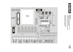
3
LINEA
POWER SUPPLY
2P+T 230V
50Hz
BLOCCO (N.C.)
STOP (N.C.)
LAMPEGGIANTE
FLASHING LIGHT
24V 4W
CL1
CM1
OP1
N
L
M
MOTORE
MOTOR
230V 50HZ
CN1
ALIMENTAZIONE FOTOCELLULE
PHOTOCELL POWER
24V 5W
F1
CN2
STOP
FINECORSA CHIUDI (N.C.)
END CLOSE (N.C.)
GND
LAMP
FOT+
FINECORSA APRI (N.C.)
END OPEN (N.C.)
GND
FCC
FCA
GND
DS1
PP
F2
ANT1 ST
2 ND
CN3
PULSANTE APRI-CHIUDI (N.O.)
PUSCH BUTTON (N.O.)
ANT+
CN4
SLOW FORCE
FOTOCELLULA - DS (N.C.)
PHOTOCELL - DS (N.C.)
12.5V
24.5V
TRASFORMATORE
TRANSFORMER
230 / 24.5V - 0.4A; 12.5V - 0.17A
ANTENNA
ITALIANO
OPENING DIRECTION: 1 MOTOR CONFIGURATION
FORT
BLUE ON COMMON
CL1
CM1
BROWN ON CLOSED
OP1
N
L
BLACK ON OPEN
CN1
F1
FORT like below:
Led “opening direction” ON: OPENS TO THE LEFT
Inner side view
FORT like below:
Led “opening direction” OFF: OPENS TO THE RIGHT
Inner side view
COMUNELLO ®Copyright 2014 - All right reserved
5
SALIENT
BLUE ON COMMON
CL1
CM1
BLACK ON CLOSED
OP1
N
L
BROWN ON OPEN
CN1
F1
SALIENT: DO NOT CHANGE the configuration!
Opens to the left, closes to the right (left profile view, as in the image).
6
COMUNELLO ®Copyright 2014 - All right reserved
ITALIANO
ISTRUZIONI D’USO E DI INSTALLAZIONE
CU - 110V - 1M
DICHIARAZIONE DI CONFORMITÁ CE
Il sottoscritto, sig. COMUNELLO LUCA rappresentante il seguente costruttore
F.lli COMUNELLO spa
Via Cassola 64, 36027 Rosà (VI) Italy
DICHIARA che l’apparecchiatura descritta in appresso:
Descrizione Modello Quadro elettronico di comando
CU 110V 1M
è conforme alle disposizioni legislative che traspongono le seguenti direttive:
• direttiva 2004/108 CE (Direttiva EMC)
• direttiva 2006/95/CE
e che sono state applicate tutte le norme e/o specifiche tecniche di seguito indicate
EN61000-6-2 + EN61000-6-3
EN62233 :2008
EN301489-1 + EN301489-3 + EN300220-2
EN60335-1 :2002
ed emendamenti successivi
Ultime due cifre dell’anno in cui è affissa la marcatura CE 14
Rosà (VI) – Italia
01-09-2014
Inoltre dichiara che non è consentito mettere in servizio il macchinario fino a che la macchina in cui sarà incorporata o di cui diverrà
componente sia stata identificata e ne sia stata dichiarata la conformità alle condizioni della Direttiva 2006/42/CE e alla legislazione
nazionale che la traspone.
Dr. LUCA COMUNELLO
Legale rappresentante della FRATELLI COMUNELLO s.p.a.
Fratelli Comunello S.p.A.
Azienda con Sistema Gestione Qualità certificato
UNI EN ISO 9001:2008.
(Certificato n° 50 100 11235 Rev. 01)
COMUNELLO ®Copyright 2014 - All right reserved
7
AVVERTENZE
•La centrale non presenta nessun tipo di
dispositivo di sezionamento della linea elettrica
110 ~, sarà quindi cura dell’installatore prevedere
nell’impianto un dispositivo di sezionamento. È
necessario installare un interruttore omnipolare
con categoria III di sovratensione. Esso deve
essere posizionato in modo da essere protetto
contro le richiusure accidentali secondo quanto
previsto al punto 5.2.9 della EN 12453. Il
cablaggio dei vari componenti elettrici esterni
alla centralina deve essere effettuato secondo
quanto prescritto dalla normativa EN 60204-1
e dalle modifiche a questa apportata dal punto
5.2.7 della EN 12453. I cavi di alimentazione
possono avere un diametro massimo di 14
mm; il fissaggio dei cavi di alimentazione e di
collegamento, deve essere garantito tramite
l’assemblaggio di pressacavi fornibili “optional”.
•Per i cavi di alimentazione si raccomanda di
utilizzare cavi flessibili sotto guaina isolante in
policloroprene di tipo armonizzato (H05RN-F)
con sezione minima dei conduttori pari a 1 mm2.
•Utilizzare in fase di installazione esclusivamente
cavi in doppio isolamento (cavi con guaina) sia per
i collegamenti a tensione di rete (110V) che per i
collegamenti in bassissima tensione di sicurezza
SELV. Utilizzare esclusivamente canalette in
plastica, distinte per i cablaggi in bassa tensione
(110V) e per i cablaggi in bassissima tensione di
sicurezza (SELV).
•I conduttori a bassissima tensione di sicurezza
devono essere fisicamente separati (almeno
4 mm in aria) dai conduttori a tensione di rete,
oppure devono essere adeguatamente isolati
con isolamento supplementare avente spessore
di almeno 1 mm.
•Prevedere a monte della rete di alimentazione
dell’automazione un dispositivo che assicuri
la disconnessione completa omnipolare della
rete, con una distanza di apertura dei contatti
in ciascun polo di almeno 3mm. Tali dispositivi
di disconnessione devono essere previsti nella
rete di alimentazione conformemente alle regole
di installazione e devono essere direttamente
collegati ai morsetti di alimentazione.
• Fare attenzione, in fase di foratura dell’ involucro
esterno per far passare i cavi di alimentazione e di
collegamento, e di assemblaggio dei pressacavi,
ad installare il tutto in modo da mantenere il più
possibile inalterate le caratteristiche di grado IP
della scatola. Prestare inoltre attenzione a fissare
i cavi in modo che siano ancorati in modo stabile,
e a non danneggiare la scheda con la foratura
(fig. 3B).
•L’involucro nella parte posteriore è provvisto di
8
COMUNELLO ®Copyright 2014 - All right reserved
opportune predisposizioni per fissaggio a muro
(predisposizione per fori per fissaggio mediante
tasselli o fori per fissaggio mediante viti).
Prevedere e implementare tutti gli accorgimenti
per una installazione che non alteri il grado IP.
•
L’eventuale montaggio di una pulsantiera
per il comando manuale deve essere fatto
posizionando la pulsantiera in modo che l’utente
non venga a trovarsi in posizione pericolosa.
•Il motoriduttore usato per muovere il cancello
deve essere conforme a quanto prescritto al
punto 5.2.7 della EN 12453.
• L’uscita FOTO+ (CN2) è necessariamente
dedicata all’alimentazione delle fotocellule, non è
consentito l’utilizzo per altre applicazioni.
•La centrale ad ogni ciclo di manovra può
effettuare il test di funzionamento delle
fotocellule, garantendo una protezione al guasto
dei dispositivi antischiacciamento di Categoria 2
secondo quanto prescritto al punto 5.1.1.6. della
EN 12453. Quindi se i dispositivi di sicurezza non
vengono connessi e/o non sono funzionanti la
centrale non è abilitata al funzionamento.
• L’apparecchio può essere utilizzato da bambini di
età non inferiore a 8 anni e da persone con ridotte
capacità fisiche, sensoriali o mentali, o prive di
esperienza o della necessaria conoscenza,
purché sotto sorveglianza oppure dopo che le
stesse abbiano ricevuto istruzioni relative all’uso
sicuro dell’apparecchio e alla comprensione
dei pericoli ad esso inerenti. I bambini non
devono giocare con l’apparecchio. La pulizia e
la manutenzione destinata ad essere effettuata
dall’utilizzatore non deve essere effettuata da
bambini senza sorveglianza.
IMPORTANTE PER L’UTENTE
• Il dispositivo non deve essere utilizzato da bambini
o da persone con ridotte capacità psico-fisiche,
almeno che non siano supervisionati o istruiti sul
funzionamento e le modalità di utilizzo.
•Non consentire ai bambini di giocare con il
dispositivo e tenere lontano dalla loro portata i
radiocomandi.
• ATTENZIONE! conservare questo manuale
d’istruzioni e rispettare le importanti prescrizioni di
sicurezza in esso contenute. Il non rispetto delle
prescrizioni potrebbe provocare danni e gravi
incidenti.
Esaminare frequentemente l’impianto per rilevare
eventuali segni di danneggiamento. Non utilizzare
il dispositivo se è necessario un intervento di
riparazione.
Alimentazione:
Uscita lampeggiante: Uscite motori:
Alimentazione fotocellule:
Sicurezze e comandi in BT:
Temperatura d’esercizio:
Ricevitore radio:
Trasmettitori op.:
Codici TX max. in memoria:
Dimensioni scheda:
110 V~ 60Hz 1600W max.
24 V~ 4W max.
110 V~ 500 W max.
24 V~ 5 W max.
24 V
-20 ÷ 55 °C
433 Mhz
18 Bit o Rolling Code
120 (CODE o CODE PED)
100x105 mm
VERIFICHE PRELIMINARI
• Verificare che il prodotto all’interno dell’imballo sia integro ed in buone
condizioni.
• Verificare che il luogo di installazione sia idoneo e rispetti le dimensioni
minime riportate in FIG. 1.
• Verificare che le fotocellule vengano fissate ad una superficie solida che
consenta un fissaggio adeguato in un punto facilmente raggiungibile in
caso di manutenzione.
INSTALLAZIONE
• Dopo aver forato la scatola ai quattro angoli fissare la centrale alla parete
(FIG. 2).
• Per il passaggio dei cavi forare la parte inferiore della scatola. (FIG. 3).
È consigliabile l’utilizzo di pressacavi.
COLLEGAMENTI ELETTRICI
CN1:
L:
Ingresso linea 110 V~ (Fase).
N:
Ingresso linea 110 V~ (Neutro).
MOT1 OPEN: Uscita Motore 1 apertura.
MOT1 COM: Uscita Motore 1 comune.
MOT1 CLOSE:Uscita Motore 1 chiusura.
CN2:
STOP: Ingresso Blocco (NC).
GND: Ingresso GND comune.
LAMP+:
Uscita Lampeggiante (24 V~ 4W max).
FOTO+:
Controllo e Alimentazione Fotocellule (24V~ 5W max).
GND:
Alimentazione comune (GND).
FCC:
Ingresso Finecorsa Chiusura Motore (NC).
FCA:
Ingresso Finecorsa Apertura Motore (NC).
GND:
Ingresso GND comune
DS1:
Ingresso Dispositivo Sicurezza (NC).
PP:
Ingresso Pulsante P/P comando apre-chiude (NA).
ANT-:
Ingresso Massa Antenna.
ANT+:
Ingresso Polo caldo Antenna
tempo motore o del raggiungimento del finecorsa apertura, la centrale
effettua l’arresto del moto (se precedentemente programmato il tempo di
pausa, la centrale allo scadere effettua la richiusura automatica . Un ulteriore
comando determina la ripresa del moto in senso opposto; se si invia un
impulso prima dello scadere del tempo motore o del raggiungimento del
finecorsa chiusura, la centrale effettua sempre l’arresto del moto. Un ulteriore
comando determina la ripresa del moto in senso opposto.
Funzionamento Passo-Passo 1:
Utilizzando sia il radiocomando (led nr 1 acceso) che i pulsanti in bassa
tensione per l’azionamento del serramento, si otterrà il seguente
funzionamento: il primo impulso comanda l’apertura fino allo scadere del
tempo motore o al raggiungimento del fine corsa d’apertura, il secondo
impulso comanda la chiusura del serramento; se si invia un impulso prima
dello scadere del tempo motore o del raggiungimento di uno dei due
finecorsa, la centrale effettua sempre l’arresto del moto sia nella fase di
apertura sia in quella di chiusura (anche se precedentemente programmato
il tempo di pausa) Un ulteriore comando determina la ripresa del moto in
senso opposto.
CHIUSURA AUTOMATICA:
La centrale permette di richiudere il serramento in modo automatico senza
l’invio di comandi supplementari. La scelta di questo funzionamento è
descritta nel modo di programmazione del Tempo di pausa.
PASSAGGIO PEDONALE:
La centrale permette, utilizzando il radiocomando (led CODE P. acceso),
l’azionamento del motore, per un tempo programmabile, tipicamente per
consentire il transito pedonale.
INGRESSO BLOCCO:
La centrale permette il collegamento di pulsante di blocco (NC).
L’intervento in qualsiasi fase di funzionamento della centrale provoca l’arresto
immediato del moto. Un ulteriore comando di moto sarà valido sempre che
sia stato disattivato l’ingresso di blocco, ed in ogni caso la centrale effettuerà
la fase di apertura dell’automatismo con prelampeggio di 5 secondi.
Attenzione: Ponticellare questo ingresso se non utilizzato.
FOTOCELLULE:
La centrale permette l’alimentazione ed il collegamento di fotocellule in
accordo alla direttiva EN 12453. L’intervento delle fotocellule nella fase di
apertura non viene considerato, nella fase di chiusura provoca l’inversione
del moto. Per consentire un funzionamento rispondente alla Categoria 2
di EN 13849-1 può essere eseguito prima di ogni manovra un test delle
fotocellule. Solo se viene superato il test la centrale avvia la manovra: in caso
contrario la centrale non consente nessun movimento e ad ogni comando
il lampeggio di tutti i led di programmazione segnala la situazione di allarme.
COLLEGAMENTI TRASFORMATORE
CN 1st:
1: Ingresso Avvolgimento Primario Trasformatore 110 V~.
2: Ingresso Avvolgimento Primario Trasformatore 110 V~.
CN 2nd:
1: Uscita SEC 1 Trasformatore 12,5V 0,17A tensioni a vuoto.
2: Uscita SEC 1 Trasformatore 12,5V 0,17A tensioni a vuoto.
3: Uscita SEC 2 Trasformatore 24,5V 0,4A tensioni a vuoto.
4: Uscita SEC 2 Trasformatore 24,5V 0,4A tensioni a vuoto.
CARATTERISTICHE FUNZIONALI
FUNZIONAMENTO AUTOMATICO
Utilizzando sia il radiocomando che la pulsantiera in bassa tensione per
l’azionamento del serramento, si otterrà il seguente funzionamento:
il primo impulso comanda l’apertura fino allo scadere del tempo motore
al raggiungimento del fine corsa d’apertura, il secondo impulso comanda
la chiusura del serramento; se si invia un impulso prima dello scadere del
tempo motore o del raggiungimento di uno dei due finecorsa, la centrale
effettua l’inversione del moto sia nella fase d’apertura sia in quella di chiusura.
FUNZIONAMENTO PASSO-PASSO:
Utilizzando sia il radiocomando che i pulsanti in bassa tensione per
l’azionamento del serramento, si otterrà il seguente funzionamento: il
primo impulso comanda l’apertura fino allo scadere del tempo motore o
al raggiungimento del fine corsa d’apertura, il secondo impulso comanda
la chiusura del serramento; se si invia un impulso prima dello scadere del
REGOLAZIONE FORZA DEL MOTORE (FORCE):
La centrale elettronica è dotata di un trimmer “FORCE” per la regolazione
della Forza dei motori, completamente gestite dal microprocessore. La
regolazione può essere effettuata con un range da 50% al 100% della Forza
massima.
Per ogni movimento è previsto comunque uno spunto iniziale, alimentando il
motore per 2 secondi alla massima potenza anche se è inserita la regolazione
della forza del motore. Nota: lo spunto iniziale è disabilitato automaticamente
se abilitata la funzione di Soft Start.
ATTENZIONE: Una variazione del trimmer “FORCE” richiede la ripetizione
della procedura di apprendimento, in quanto potranno variare i tempi di
manovra e di rallentamento
RALLENTAMENTO (SLOW):
La funzione di rallentamento dei motori è usata nei cancelli per evitare la
battuta a forte velocità delle ante mobili al termine della fase di apertura e
chiusura.
La centrale consente durante la programmazione del tempo motore (vedi
menù Principale) anche la programmazione del rallentamento nei punti
desiderati (prima della totale apertura e chiusura), inoltre tramite il trimmer
“SLOW” è possibile fare una regolazione fine su tre livelli dell’intensità della
velocità durante la fase di rallentamento.
COMUNELLO ®Copyright 2014 - All right reserved
9
ITALIANO
CARATTERISTICHE TECNICHE
FUNZIONAMENTO CON TIMER:
La centrale permette di collegare al posto del pulsante di comando apre–
chiude un timer.
Esempio: ore 08.00 il timer chiude il contatto e la centrale comanda l’apertura,
ore 18.00 il timer apre il contatto e la centrale comanda la chiusura. Durante
l’intervallo 08.00–18.00 al termine della fase di apertura la centrale disabilita
il lampeggiante, la chiusura automatica e i radiocomandi.
PROGRAMMAZIONE:
Tasto SELECT: seleziona il tipo di funzione da memorizzare, la selezione è
indicata dal lampeggio del Led.
Premendo più volte il tasto, è possibile posizionarsi sulla funzione desiderata.
La selezione resta attiva per 10 secondi, visualizzata dal led lampeggiante,
se trascorsi, la centrale ritorna allo stato originario.
Tasto SET: effettua la programmazione dell’informazione secondo il tipo di
funzione prescelta con il tasto SEL.
IMPORTANTE: la funzione del tasto SET può anche essere sostituita dal
radiocomando se precedentemente programmato (led CODE acceso).
Programmazione abilitata solo a sicurezze non attive.
MENÙ PRINCIPALE
La centrale è fornita dal costruttore con la possibilità di selezionare alcune
funzioni importanti.
L1
L2
L3
L4
L5
L6
L7
LEV
DIR
STEP BY STEP
CODE TX
CONDO
MOTOR TIME
PAUSE TIME
AUTO PROGRAM
MENÙ
Apre a sinistra
Passo – Passo/PP1
Codice inserito
ON
Tempo programmato
Con chiusura automatica
ON
Apre a destra
Automatico
Nessun codice
OFF
30 sec.
Senza chiusura automatica
OFF
ON
1. DIREZIONE DI APERTURA (DIR):
La centrale nella configurazione di default presenta la logica di “APRE A
DESTRA” (vista lato motore, motore installato a destra dell’anta scorrevole);
se occorre abilitare la logica di “APRE A SINISTRA” (vista lato motore,
motore installato a sinistra dell’anta scorrevole), procedere nel seguente
modo: posizionarsi con il tasto SELECT sul lampeggio del LED DIR e
premere il tasto SET: il LED DIREZ APRE si accenderà permanentemente
e la programmazione sarà completata. Ripetere l’operazione se si desidera
ripristinare la configurazione precedente.
2. STEP BY STEP:
La centrale nella configurazione di default presenta la logica di funzionamento
“ Automatico ” abilitato (LED NR 2 spento);
se si desidera abilitare la logica di funzionamento P/P “ Passo – Passo “,
procedere nel seguente modo: posizionarsi con il tasto SEL sul lampeggio
del LED NR 2. e poi premere il tasto SET:
il LED NR 2 si accenderà permanentemente e la programmazione sarà
conclusa. Se si desidera abilitare la logica di funzionamento P/P1 “ Passo
– Passo 1, ripetere l’operazione sopra descritta, premendo il tasto SEL
due volte (ottenendo il lampeggio veloce del LED NR 2) anziché una volta.
Ripetere l’operazione se si desidera ripristinare la configurazione iniziale.
3. CODE TX: (Codice del radiocomando)
La centrale permette di memorizzare fino a 120 radiocomandi aventi codice
diverso fra loro di tipo fisso o rolling code.
Programmazione:
La programmazione del codice di trasmissione è eseguita nel seguente
modo: posizionarsi con il tasto SELECT sul lampeggio del LED L3. Premere 1
volta SET, il led modificherà il proprio lampeggio (1 0 1 0 più lungo) indicando
che si sta memorizzando il primo livello. Inviando il codice prescelto con il
radiocomando desiderato, il LED CODE resterà acceso permanentemente
indicando che la programmazione sarà completata.
Per memorizzare il codice per l’apertura pedonale / anta singola procedere
come di seguito: posizionarsi con il tasto SELECT sul lampeggio del LED
L3 CODE. Premere 2 volte consecutive SET, il led modificherà il proprio
lampeggio (1 1 0 1 1 0) indicando che si sta memorizzando il codice
pedonale LED CODE PED. Inviando il codice prescelto con il radiocomando
desiderato, il LED L3 CODE resterà acceso permanentemente indicando
che la programmazione sarà completata.
10
COMUNELLO ®Copyright 2014 - All right reserved
Nel caso che tutti i 120 codici siano stati memorizzati, ripetendo l’operazione
di programmazione, tutti i LED di programmazione inizieranno a lampeggiare
segnalando che non sono possibili ulteriori memorizzazioni.
Cancellazione:
Posizionarsi con SELECT sul LED L3; attivare il lampeggio del codice da
cancellare (CODE o PEDONALE identificati dal rispettivo lampeggio);
premere e tener premuto SET per un tempo > 5 s. Alla fine il led si spegnerà
per 2 sec e la procedura è completata. Se si eliminano tutti i codici sia
CODE che PEDONALI, il led rimarrà spento.
Se rimarranno memorizzati solo codici PEDONALI, il led lampeggerà in
modo diverso (1 1 1 1 0 1 1 1 1 0)
Regola del primo Radiocomando memorizzato:
Nella programmazione dei radiocomandi vige la seguente regola: se il primo
radiocomando ad essere memorizzato è un radiocomando di tipo rolling
code il ricevitore accetterà poi solo radiocomandi rolling code, garantendo
così una maggiore sicurezza antintrusione; se invece il primo radiocomando
ad essere memorizzato è un radiocomando a codice fisso il ricevitore
accetterà poi sia radiocomandi a codice fisso che radiocomandi rolling
code, controllando però di questi ultimi soltanto la parte fissa (perdendo in
sostanza la sicurezza del sistema rolling).
ATTENZIONE: Ogni volta che si effettua un reset il ricevitore viene riportato
alla configurazione di fabbrica, e viene quindi azzerata la regola del primo
radiocomando.
4. CONDO:
Il funzionamento Condominiale prevede che la centrale durante la fase
apertura o durante la pausa non senta i comandi provenienti dai Pulsanti
e dai radiocomandi. Nella fase di chiusura invece un comando proveniente
dai pulsanti o dai radiocomandi provoca l’inversione del moto. Questa
modalità di funzionamento è particolarmente utilizzata quando l’automazione
è comprensiva di un loop detector.
La centrale nella configurazione di default, presenta la funzione condominiale
disabilitata, se occorre abilitarla, procedere nel seguente modo: posizionarsi
con il tasto SELECT sul lampeggio del LED L4 e poi premere il tasto SET:
il LED L4 si accenderà permanentemente e la programmazione sarà
conclusa. Ripetere l’operazione se si desidera ripristinare la configurazione
precedente.
5. MOTOR TIME:
(Program. tempo di lavoro dei motori 4 minuti max.) La centrale è fornita
dal costruttore con un tempo di lavoro motore predefinito pari a 30 sec.
e senza rallentamento. Se occorre modificare il tempo di lavoro motore, la
programmazione deve essere effettuata a serramento chiuso nel seguente
modo: posizionarsi con il tasto SELECT, sul lampeggio del LED L5 poi
premere per un istante il tasto SET, il Motore inizierà ciclo di apertura, al
raggiungimento del punto iniziale desiderato di rallentamento, premere
nuovamente il tasto SET, allo stesso tempo il motore effettua il rallentamento
fino alla posizione desiderata, premere il tasto SET per concludere il ciclo di
apertura. Successivamente il LED L5 inizierà a lampeggiare velocemente, ora
ripetere l’operazione di programmazione del tempo motore e rallentamento
per il ciclo di chiusura. Se non si desidera che la centrale effettui il
rallentamento, durante la programmazione, al completamento del ciclo
di apertura e chiusura, premere il tasto SET due volte consecutivamente
anziché una sola. Durante la programmazione è possibile usare al posto
del tasto SET, posto sulla centrale, il tasto del radiocomando solamente se
precedentemente memorizzato.
6. PAUSE TIME
(Programmazione tempo chiusura aut. 4 min. max.) La centrale è fornita dal
costruttore senza chiusura automatica. Se si desidera abilitare la chiusura
automatica, procedere nel seguente modo: posizionarsi con il tasto SELECT
sul lampeggio del LED L6 e premere per un istante il tasto SET, attendere
poi per un tempo uguale a quello desiderato; premere nuovamente per un
istante il tasto SET, nello stesso momento si determinerà la memorizzazione
del tempo di chiusura automatica e il LED L6 sarà acceso fisso. Se si
desidera ripristinare la condizione iniziale (senza chiusura automatica),
posizionarsi sul lampeggio del LED L6 poi premere consecutivamente per 2
volte il tasto SET in un intervallo di tempo di 2 secondi. Il led si spegnerà e
l’operazione sarà conclusa.
Durante la programmazione è possibile usare al posto del tasto SET, posto
sulla centrale, il tasto del radiocomando solamente se precedentemente
memorizzato
7. PROGRAMMAZIONE AUTOMATICA (AUTO PROGRAM)
La centrale permette di effettuare una Programmazione Automatica
(SEMPLIFICATA).
Per prima cosa porre le ante dell’automazione in posizione intermedia,
MENÙ ESTESO 1
La centrale è fornita dal costruttore con la possibilità di selezione diretta
solamente delle funzioni del menù principale. Se si desidera abilitare le
funzioni descritte nel Menù Esteso 1, procedere nel seguente modo:
posizionarsi sul lampeggio del led LEV e premere 1 volta SET. Il led inizierà
a lampeggiare. In questo modo si avranno 30 secondi di tempo per
selezionare le funzioni del Menù Esteso 1 mediante l’uso dei tasti SELECT
e SET; trascorsi ulteriori 30 secondi la centrale ritorna al menù principale.
L1
L2
L3
L4
L5
L6
L7
LEV
FOTOTEST
TEMPO PEDONALE
RALLENTAMENTO
FRENO ELETTRONICO
COLPO D'ARIETE
COLPO IN CHIUSURA
LUCE DI CORTESIA / PRELAMPEGGIO
MENÙ
ON
ON
OFF
ON
ON
ON
ON
OFF
OFF
ON
OFF
OFF
OFF
OFF
1 LAMPEGGIO
1. TEST FOTOCELLULE (Foto Test)
La centrale è fornita dal costruttore con il test delle fotocellule disabilitato, se
si desidera abilitare la funzione, procedere nel seguente modo: assicurarsi
di aver abilitato il Menù Esteso 1, posizionarsi con il tasto SELECT sul
lampeggio del led L1 poi premere il tasto SET, nello stesso istante il LED L1
si accenderà permanentemente e la programmazione sarà conclusa.
Ripetere l’operazione se si desidera ripristinare la configurazione precedente.
2. TEMPO PEDONALE: (Program. tempo di lavoro pedonale 4 minuti
max.)
La centrale è fornita dal costruttore con un tempo di lavoro del Motore
(Pedonale) predefinito pari a 10 secondi e senza rallentamento.
Se occorre modificare il tempo di lavoro pedonale, la programmazione deve
essere effettuata a serramento chiuso nel seguente modo: assicurarsi di aver
abilitato il Menù Esteso 1, posizionarsi con il tasto SELECT sul lampeggio
del led L2. poi premere per un istante il tasto SET, il Motore inizierà ciclo di
Apertura; in corrispondenza del punto iniziale desiderato di rallentamento
premere nuovamente il tasto SET: il LED L2 inizierà a lampeggiare più
lentamente e il Motore effettuerà il rallentamento; al raggiungimento della
posizione desiderata premere il tasto SET per concludere il ciclo di Apertura.
A questo punto il LED L2 tornerà a lampeggiare regolarmente e il Motore
ripartirà in Chiusura; ripetere le operazioni viste sopra, per la fase di Chiusura.
Se non si desidera che la centrale effettui il rallentamento, durante la
programmazione, al completamento del ciclo di apertura e chiusura,
premere il tasto SET due volte consecutivamente anziché una sola.
Durante la programmazione è possibile usare al posto del tasto SET, posto
sulla centrale, il tasto del radiocomando solamente se precedentemente
memorizzato.
3. RALLENTAMENTO
Come detto precedentemente la centrale permette la programmazione
di una fase di rallentamento in apertura e chiusura. Qualora però non si
desideri avere alcun rallentamento, è possibile escluderlo. Se prima
di escludere il rallentamento esso era stato programmato mediante la
funzione di Programmazione dei Tempi Motore sarà necessario ripetere
la programmazione da capo. Se si desidera escludere il rallentamento
procedere nel seguente modo: assicurarsi di aver abilitato il Menù Esteso 1,
posizionarsi con il tasto SELECT sul lampeggio del LED L3 e poi premere il
tasto SET: Il LED L3 si accenderà permanentemente e la programmazione
sarà conclusa. Ripetere l’operazione se si desidera ripristinare la
configurazione precedente.
4. FRENO ELETTRONICO:
La centrale è fornita dal costruttore con la funzione di freno elettronico
disabilitata. Se si desidera abilitare la funzione, procedere nel seguente
modo: assicurarsi di aver abilitato il Menù Esteso 1, posizionarsi con il tasto
SELECT sul lampeggio del led L4 poi premere il tasto SET, nello stesso
istante il LED L4 si accenderà permanentemente e la programmazione sarà
conclusa.
In questo modo la centrale riduce l’avanzamento del cancello dovuto
all’inerzia, in corrispondenza di un arresto o di un comando d’inversione.
Ripetere l’operazione se si desidera ripristinare la configurazione precedente.
5. COLPO D’ARIETE
La centrale è fornita dal costruttore con la funzione di Colpo d’Ariete
disabilitata. Se si desidera abilitare la funzione di Colpo d’Ariete alla massima
potenza, procedere nel seguente modo: assicurarsi di aver abilitato il
Menù Esteso 1, posizionarsi con il tasto SELECT sul lampeggio del LED
L5. poi premere il tasto SET, nello stesso istante il LED L5 si accenderà
permanentemente e la programmazione sarà conclusa. Se si desidera
abilitare la funzione di Colpo d’Ariete alla potenza impostata tramite il Trimmer
“FORCE”, ripetere l’operazione sopra descritta,
premendo il tasto SELECT due volte (ottenendo il lampeggio veloce del
LED L5 anziché una volta. Ripetere l’operazione se si desidera ripristinare
la configurazione iniziale.
In questo modo possiamo facilitare lo sblocco della serratura e quindi
permettere la corretta esecuzione della fase di apertura. La centrale infatti
prima d’iniziare la fase di apertura invia un comando di chiusura per 2
secondi con potenza relativa alla scelta selezionata.
6. COLPO IN CHIUSURA
La centrale è fornita dal costruttore con la funzione di Colpo in Chiusura
disabilitata. Tale funzione consiste nell’aggiungere, nel caso sia presente
una fase di rallentamento in chiusura, un tempo di 1 secondo, alla
potenza massima oppure alla potenza selezionata mediante trimmer
“FORCE”, in modo da sormontare un’eventuale serratura installata. Se si
desidera abilitare la funzione di Colpo in Chiusura alla massima potenza,
procedere nel seguente modo: assicurarsi di aver abilitato il Menù Esteso 1,
posizionarsi con il tasto SELECT sul lampeggio del LED L6 e poi premere il
tasto SET: il led L6. si accenderà permanentemente e la programmazione
sarà conclusa. Se si desidera abilitare la funzione di Colpo in Chiusura alla
potenza impostata tramite il Trimmer “FORCE”, ripetere l’operazione sopra
descritta, premendo il tasto SELECT due volte (ottenendo il lampeggio
veloce del LED L6.) anziché una volta. Ripetere l’operazione se si desidera
ripristinare la configurazione iniziale.
7. PRELAMPEGGIO/LUCE DI CORTESIA
La centrale è fornita dal costruttore con le funzioni Prelampeggio e Luce
di Cortesia disabilitate. Se si desidera abilitare la funzione Prelampeggio,
procedere nel seguente modo: assicurarsi di aver abilitato il Menù Esteso
1, posizionarsi con il tasto SEL sul lampeggio del LED L7 e poi premere il
tasto SET: il led si accenderà permanentemente e la programmazione sarà
conclusa. Se si desidera abilitare la funzione di Luce di Cortesia, ripetere
l’operazione sopra descritta, premendo il tasto SET due volte (ottenendo
il lampeggio veloce del LED) anziché una volta. Ripetere l’operazione se si
desidera ripristinare la configurazione iniziale.
Funzionamento Prelampeggio: L’uscita Lampeggiatore 24 ~ 4W max. si
attiverà sempre 3 secondi prima della manovra di chiusura.
Funzionamento Luce di Cortesia: L’uscita Lampeggiatore 24 ~ 4W max.
si attiverà per la durata di 3 minuti, ogni qualvolta che sarà impartito un
comando di apertura.
MENÙ ESTESO 2
La centrale è fornita dal costruttore con la possibilità di selezione diretta
solamente delle funzioni del menù principale. Se si desidera abilitare le
funzioni descritte nel Menù Esteso 2, procedere nel seguente modo:
posizionarsi sul lampeggio del LED LEV e premere 2 volte SET. Il led inizierà a
lampeggiare in modo alternato 1 1 0 1 1 0 1 1 0. in questo modo si avranno
30 secondi di tempo per selezionare le funzioni del Menù Esteso 2 mediante
l’uso dei tasti SELECT e SET, poi dopo ulteriori 30 secondi la centrale ritorna
al menù principale.
L1
L2
L3
L4
L5
L6
SOFT STOP
SOFT START
DS1 IN APRE
UOMO PRESENTE
FOLLOW ME
LAMP PAUSA
ON
ON
ON
ON
ON
ON
OFF
OFF
OFF
OFF
OFF
OFF
COMUNELLO ®Copyright 2014 - All right reserved
11
ITALIANO
posizionarsi con il tasto SELECT sul lampeggio del LED L7 e poi premere
in modo continuo il tasto SET, la centrale completa la fase di Auto
programmazione eseguendo un’apertura e chiusura completa (mantenere
sempre premuto il tasto SET fino al termine dell’ Auto Programmazione).
Nello stesso viene Automaticamente impostato il ciclo di Rallentamento pari
a circa il 15% del ciclo completo.
Durante la Programmazione Automatica è possibile usare al posto del
tasto SET, posto sulla centrale, il tasto del radiocomando solamente se
precedentemente memorizzato.
ATTENZIONE: con l’utlizzo della Programmazione automatica è necessario
collegare i finecorsa FCC e FCA
L7
LEV
CHIUDI SEMPRE
MENÙ
ON
OFF
2 LAMPEGGI
Menù 2, posizionarsi con il tasto SEL sul lampeggio del LED L7 e poi premere
il tasto SET: il LED L7 si accenderà permanentemente e l’operazione sarà
conclusa. Ripetere l’operazione se si desidera ripristinare la configurazione
precedente.
1. SOFT STOP:
La centrale è fornita dal costruttore con la funzione Soft Stop disabilitata. Se
si desidera abilitare la funzione, procedere nel seguente modo: assicurarsi di
aver abilitato il Menù Esteso 2 posizionarsi con il tasto SEL sul lampeggio del
LED L1 e poi premere il tasto SET, nello stesso istante il LED L1 si accenderà
permanentemente e la programmazione sarà conclusa. In questo modo, la
centrale alla fine del moto, porterà la forza a zero in modo graduale entro 2
secondi. Ripetere l’operazione se si desidera ripristinare la configurazione
precedente.
RESET
2. SOFT START
La centrale è fornita dal costruttore con la funzione Soft Start disabilitata. Se
si desidera abilitare la funzione, procedere nel seguente modo: assicurarsi
di aver abilitato il Menù Esteso 2 posizionarsi con il tasto SELECT sul
lampeggio del LED L2 e poi premere il tasto SET, nello stesso istante il LED
L2 si accenderà permanentemente e la programmazione sarà conclusa. In
questo modo, la centrale ad ogni inizio di moto, controllerà la partenza del
motore, portando la forza in modo graduale, dal minimo al valore impostato
dal trimmer “FORCE” nei primi 2 secondi di funzionamento. Ripetere
l’operazione se si desidera ripristinare la configurazione precedente. Nota:
quando abilitata la funzione Soft Start la centrale disabilita automaticamente
lo Spunto Iniziale e viceversa.
Test Fotocellula:
La centrale è predisposta per la connessione di dispositivi di sicurezza
che rispettano il punto 5.1.1.6 della normativa EN 12453. Ad ogni ciclo di
manovra viene effettuato il test di funzionamento della fotocellula collegata.
Nel caso di mancato collegamento e/o non funzionamento, la centrale non
abilita il movimento del serramento ed evidenzia visivamente il fallimento del
test effettuando il lampeggio contemporaneo di tutti i Led di segnalazione.
Una volta ripristinato il corretto funzionamento della fotocellula, la c entrale è
pronta per il normale utilizzo. Ciò garantisce un monitoraggio contro i guasti
conforme alla Categoria 2 della EN 954-1.
3. DS 1 IN APRE
La centrale consente di modificare il funzionamento dell’ingresso DS1. Se
si desidera che SAFE 1 intervenga anche in apertura (arresto momentaneo
del serramento, una volta liberato la centrale riprende il moto in apertura),
procedere nel seguente modo: assicurarsi di aver abilitato il Menù Esteso 2
posizionarsi con il tasto SEL sul lampeggio del LEDL3 e poi premere il tasto
SET: il LED L3 sii accenderà permanentemente e la programmazione sarà
conclusa. Ripetere l’operazione se si desidera ripristinare la configurazione
iniziale.
4. UOMO PRESENTE
La centrale permette di impostare il funzionamento “Uomo presente”. Se
si desidera tale modalità di funzionamento procedere nel seguente modo:
assicurarsi di aver abilitato il Menù Esteso 2posizionarsi con il tasto SELECT
sul lampeggio del LED L4. e poi premere il tasto SET: il LED L4 si accenderà
permanentemente e l’operazione sarà conclusa. In questo modo, utilizzando
sia i radiocomandi che i Pulsanti per l’azionamento del serramento, si otterrà
il seguente funzionamento: occorrerà mantenere costantemente attivato
il comando desiderato per ottenere il moto del serramento. Il rilascio del
comando provocherà l’arresto immediato del moto. Ripetere l’operazione se
si desidera ripristinare la configurazione precedente.
5. FOLLOW ME
La centrale permette di impostare il funzionamento “Follow me”: tale funzione,
programmabile solo se è già stato programmato un Tempo di Pausa, prevede
di ridurre il tempo di Pausa a 5 sec. dopo il disimpegno della fotocellula DS1,
ossia il serramento si richiude 5 sec. dopo che l’utilizzatore è transitato. Per
attivare tale funzione procedere nel seguente modo: assicurarsi di essere
nel Menù 2 posizionarsi con il tasto SELECT sul lampeggio del LED L5
e poi premere il tasto SET: il LED L5 si accenderà permanentemente e
la programmazione sarà conclusa. Ripetere l’operazione se si desidera
ripristinare la configurazione precedente.
6. FUNZIONAMENTO LAMPEGGIANTE (Lamp. Pausa)
La centrale è fornita dal costruttore con il funzionamento del Lampeggiante
durante il Tempo di Pausa disabilitato. Se si desidera abilitare il
funzionamento, procedere nel seguente modo: assicurarsi di aver abilitato
il Menù Esteso 2posizionarsi con il tasto SELECT sul lampeggio del LED
L6 e poi premere il tasto SET: il LED L6 si accenderà permanentemente
e la programmazione sarà conclusa. Ripetere l’operazione se si desidera
ripristinare la configurazione precedente.
7. CHIUDI SEMPRE
La centrale permette di impostare il funzionamento “Chiudi Sempre”: tale
funzione, programmabile solo se è già stato programmato un Tempo
di Pausa, interviene dopo una mancanza di alimentazione; se viene
rilevato che il cancello è aperto si avvia automaticamente una manovra di
chiusura preceduta da 5s. di prelampeggio. Se si desidera tale modalità
di funzionamento procedere nel seguente modo: assicurarsi di essere nel
12
COMUNELLO ®Copyright 2014 - All right reserved
Nel caso sia opportuno ripristinare la centrale alla configurazione di fabbrica,
premere il tasto SELECT e SET in contemporanea, allo stesso tempo si
otterrà l’accensione contemporanea di tutti i led ROSSI di segnalazione e
subito dopo lo spegnimento.
DIAGNOSTICA
Test input comandi:
In corrispondenza ad ogni ingresso di comando in bassa tensione, la
centrale dispone di un LED di segnalazione, in modo tale da poter controllare
rapidamente lo stato.
Logica di funzionamento: LED acceso ingresso chiuso, LED spento ingresso
aperto.
GARANZIA
Fratelli Comunello SpA garantisce, a condizione del rispetto delle speciche
prestazionali indicate nei manuali di istruzione dei prodotti, il corretto funzionamento
degli attuatori per 24 mesi dalla data di fabbricazione. Fratelli Comunello S.p.a.
garantisce in via esclusiva, e quindi con esclusione di domande risarcitorie
formulate per equivalente, la riparazione o sostituzione gratuita delle parti
difettose che verranno riconosciute tali, secondo l’insindacabile giudizio tecnico
del personale di Fratelli Comunello SpA. Il materiale in garanzia inviato alla sede
della Fratelli Comunello SpA, dovrà essere spedito in porto franco e verrà quindi
rispedito in porto assegnato. Il materiale ritenuto difettoso ed inviato a Fratelli
Comunello S.p.a. rimarrà di proprietà di quest’ultima società.
- Il costo di manodopera necessario per le riparazioni e sostituzioni eseguite
rimane a carico dell’acquirente. Non viene riconosciuto alcun indennizzo per il
periodo d’inoperatività dell’impianto. L’intervento non prolunga la durata della
garanzia. A pena di decadenza, l’acquirente deve denunciare gli eventuali vizi e
difetti dei prodotti, entro il termine di 8 (otto) giorni da calcolarsi rispettivamente
dalla data di scoperta dei vizi o dalla data di consegna della merce. La denuncia
dovrà essere fatta esclusivamente per iscritto. La garanzia non comprende:
Avarie o danni causati dal trasporto; avarie o danni causati da vizi dell’impianto
elettrico presente presso l’acquirente il prodotto e/o da trascuratezza, negligenza,
inadeguatezza, uso anomalo di tale impianto; avarie o danni dovuti a manomissioni
poste in essere da parte di personale non autorizzato o conseguenti allo scorretto
uso/installazione (a questo proposito, si consiglia una manutenzione del sistema
almeno ogni sei mesi) o all’impiego di pezzi di ricambio non originali; difetti causati
da agenti chimici e/o fenomeni atmosferici.
La garanzia non comprende il costo per materiale di consumo né quello per vizi
presunti o veriche di comodo.
Caratteristiche dei prodotti
I prodotti realizzati da Fratelli Comunello SpA sono soggetti a continue innovazioni
e miglioramenti; pertanto, le caratteristiche costruttive e l’immagine degli stessi,
potranno subire variazioni anche senza preavviso.
Foro competente
Poiché il contratto viene perfezionato mediante Conferma d’Ordine compilata in
Rosà, in caso di controversia legale di qualsiasi natura è applicabile il diritto italiano
ed è competente il Foro di Vicenza (VI).
INSTALLATION AND USER’S MANUAL
CU - 110V - 1M
EC DECLARATION OF COMFORMITY:
ENGLISH
The undersigned Mr. Luca Comunello, representing the following manufacturer,
Fratelli COMUNELLO Spa
Via Cassola 64, 36027 Rosà (VI) – Italy
DECLARES that the equipment described below:
Description: Model: Electronic control unit
CU 110V 1M
Is in compliance with the provisions set down in the following directives:
• 2004/108 EC Directive (EMC Directive)
• 2006/95/CE Directive
and that all the rules and/or technical specifications shown below have been applied:
EN61000-6-2 + EN61000-6-3
EN62233 :2008
EN301489-1 + EN301489-3 + EN300220-2
EN60335-1 :2002
and the following amendments.
Last two digits of the year in which the EC marking has been affixed
14
Rosà (VI) – Italia
01-09-2014
and he also declares that it is not allowed to commission the device until the machinery where it will be incorporated or whose it will
become a component will have been identified and will have been declared in compliance with the conditions of the 2006/42 EC Directive
and with the national legislation that transpose it.
Mr. Luca Comunello
Fratelli Comunello Legal Representative
Fratelli Comunello S.p.A.
Company with certified Quality Management System
UNI EN ISO 9001:2008.
(Certificate n° 50 100 11235 Rev. 01)
COMUNELLO ®Copyright 2014 - All right reserved
13
PRESCRIPTIONS
•The control unit is not equipped with a device for
disconnection of the 110 ~ power supply line. It
is therefore the responsibility of the installer to fit
a disconnection device in the electrical system.
The disconnection device must be composed of
a category III overvoltage all-pole circuit breaker.
This device must be positioned in consideration
of the need to be protected against inadvertent
reconnection in compliance with the requirements
of EN 12453 point 5.2.9. Wiring of the external
electrical devices to the control unit must be carried
out in compliance with the prescriptions of EN
60204-1 as amended by EN 12453 point 5.2.7.
The maximum diameter of power feeding cables
is 14 mm; fixing of power feeding and connection
cables must be assured by fitting cable glands,
which can be supplied as optionals.
• The power input cables must be of the standardized
flexible type with polychloroprene sheath (H05RN-F)
having minimum conductor size of 1 mm2.
• During the installation operations, take care to use
cable with double insulation only (sheathed cables)
for both of mains voltage connections (110V)
and extra-low voltage connections (SELV). Use
exclusively plastic cable trays, separated for mains
voltage wiring (110V) and extra-low voltage wiring
(SELV).
• The extra low voltage conductors must be physically
separated (at least 4 mm in air) from the mains
voltage wires, or shall be adequately insulated with
extra insulation with a thickness of at least 1 mm.
•Upstream of main supply, install a device that
ensures the complete omnipolar disconnection
(cut-off switch) of the power supply, with a contact
opening gap of at least 3mm in each pole. These
disconnecting devices shall be places in the power
supply wiring in compliance with the installation
standards and must be directly connected to the
supply terminals.
•When drilling the outer case to insert the power
and connection cables and when fitting the cable
glands, take care to install all the parts in a manner
that maintains the IP protection characteristics of
the box unchanged as far as possible. Ensure the
cables are fixed in a stable and secure manner.
•The rear of the box is equipped with knockouts
for wall fixing (knockouts for fixing holes using
anchor bolts or holes for fixing with screws). Take
all the measures required to ensure the installation
14
COMUNELLO ®Copyright 2014 - All right reserved
procedures do not affect the IP rating.
• If required, a pushbutton panel for manual control
of the gate must be installed in a position such as
to ensure the user is not placed in danger.
• The operator utilized to move the gate must be in
compliance with the prescriptions of EN 12453,
point 5.2.7.
•Power Supply output D.S. must be used for
photocells. Alternative uses of this output are not
permitted.
•At each operating cycle, the control unit can test
the photocells operation to ensure protection
against failure of anti-crushing protective devices
according to Category 2 in compliance with the
prescriptions of EN 12453 point 5.1.1.6. It follows
that if the safety devices are not connected or are
faulty, operation of the control unit will be inhibited.
• The device can be used by children no older than
8 years old and people with reduced physical,
sensory or mental capabilities, or lack of experience
or without the required knowledge, but only under
surveillance or after having received instructions
about the safe use of the device and the hazards
inherent in it. Children should not play with the
device. Cleaning and maintenance should not be
carried out by children without supervision.
For correct operation of the radio receiver section,
when using two or more control units it is good
practice to install them at a minimum distance of 3
metres from one another.
All operations that require the control unit box to be
opened (connection of cables, programming, etc.)
must be carried out by expert personnel at the time
of installation. For all further operations that require the
box to be re-opened
IMPORTANT INFORMATION FOR USERS
•The device must not be used by minors or
psychologically-physically differently-abled persons
unless they are supervised or duly instructed on
the operation and methods of use.
•Do not let children play with the device and keep
the remotes out of their reach.
• IMPORTANT: keep this instruction manual and
comply with the safety prescriptions set down
herein. Failure to comply with the prescriptions may
cause damage and serious accidents.
Frequently examine the system to identify any signs of
damage. Do not use the device if repairs are required.
TECHNICAL SPECIFICATIONS
Power supply
: 110 V~ 60Hz 1600W max.
Flashing light output
: 24 V~ 4W max.
Operator outputs
: 110 V~ 500 W max.
Photocells power supply : 24 V~ 5 W max. LV safeties and controls : 24 V
Working temperature
: -20 55 °C
Radio receiver
: 433 Mhz
Transmitters
: 18 Bit or Rolling Code
Max TX codes stored in memory: 120 (CODE or PED CODE) - Board
dimensions
: 100x105 mm
• Check that the product in the pack is intact and in good condition
• Check that the place of installation is suitable and in compliance with the
minimum dimensions shown in figure 1
INSTALLATION
• Drill the box in the four corners and then fix the control unit to the wall
(FIG. 2)
• Drill a hole in the underside of the box for the cable inlet. (FIG.3) The use
of cable glands is recommended.
CONNECTIONS
CN1:
L: 110 V~ line input (phase).
N: 110 V~ line input (neutral).
OPEN1: Operator 1 opening output.
COM1: Operator 1 output common.
CLOSE1: Operator 1 closing output.
CN2:
STOP: Emergency stop input (NC)
GND:
Common GND input
LAMP+: Flashing light output (24 V~ 4W max).
FOTO+: Photocells Control and Power Supply (24V~ 5W max).
GND: Common power supply (GND).
FCC: Operator Closing Limit Switch Input (NC).
FCA: Operator Opening Limit Switch Input (NC).
GND: Common GND input
SAFE1: Safety Device Input (NC).
PP: Pedestrian Pushbutton open-close command input (NO).
ANT: Antenna Ground Input.
ANT+: Antenna Hot pole input.
AUTOMATIC CLOSING:
The control unit can be set up to close the gate automatically without
sending any additional commands.
The selection of this type of operation is described in Pause time
programming mode.
PEDESTRIAN OPENING:
By means of the radio remote control (CODE P. LED on) the control unit
makes it possible to drive the Operator for a programmable time, typically
to allow pedestrian access.
EMERGENCY STOP INPUT:
The control unit allows the connection of an emergency stop pushbutton
(NC). Pressing this pushbutton irrespective of the current operating mode
of the control unit will cause immediate stopping of the gate movement. An
additional gate movement command will be valid provided the emergency
stop input is deactivated and, in any case, the control unit will execute the
gate opening cycle with 5 seconds preflashing.
IMPORTANT: Jumper this input if it is not to be used.
PHOTOCELLS:
Photocells can be powered by and connected to the control unit in
accordance with directive EN 12453. Tripping of the photocells during
opening is disregarded, while during closing it causes reversal of the
direction of movement.
To allow operation in compliance with EN 13849-1 Category 2 a photocell
test is performed before each movement. The control unit enables the
movement only if the test is passed; if it is not, the control unit inhibits
all movements and an alarm condition is signalled by blinking of all the
programming LEDs on transmission of any command.
TRANSFORMER CONNECTIONS
CN3 1st:
1 : 110 V~ Transformer Primary Winding Input.
2 : 110 V~ Transformer Primary Winding Input.
CN4 2nd:
1. Transformer SEC 1 Output 12.5V 0.17A no-load voltages.
2. Transformer SEC 1 Output 12.5V 0.17A no-load voltages.
3. Transformer SEC 2 Output 24.5V 0.4A no-load voltages.
4. Transformer SEC 2 Output 24.5V 0.4A no-load voltages.
FUNCTIONAL CHARACTERISTICS
AUTOMATIC OPERATION:
When either the remote or the low voltage pushbutton is used to control the
gate, operation is as follows:
the first command opens the gate until motor time elapses or until the gate
reaches its opening limit position; the second command closes the gate; if
another command is transmitted before motor time has elapsed or before
one of the two limit stops has been reached, the control unit reverses the
movement direction during both opening and closing.
STEP-BY-STEP OPERATION:
When either the remote or the low voltage control pushbuttons are used to
control the gate, operation is as follows:
the first command opens the gate until motor time or until the gate
reaches its opening limit position; the second command closes the gate;
if another command is transmitted before motor time has elapsed or
before one of the limit stops has been reached, the control unit stops the
movement. Another command causes the gate to start moving again in the
opposite direction.
OPERATOR FORCE ADJUSTMENT (FORCE):
The electronic control unit is equipped with a “FORCE” trimmer for
adjustment of the Force delivered by the operators, completely managed
by the microprocessor. Adjustment can be performed in a range of between
50% and 100% of maximum force. Initial starting torque can be set for each
movement by feeding the operator at full power for 2 seconds, even if
operator force control is enabled. Note: initial starting torque is disabled
automatically if the Soft Start function is enabled.
IMPORTANT: If the “FORCE” trimmer is adjusted, the self-learning
procedure must be repeated because the movement and deceleration
times may change.
DECELERATION (SLOW):
The operators deceleration function is used on gates to prevent the moving
leaves from slamming at speed into the limit stops at the end of the opening
and closing strokes. During Motor Time programming (see Main menu)
the control unit allows programming of deceleration in the required points
(immediately before full opening and full closing); in addition, using the
“SLOW” trimmer the force intensity can be adjusted during the deceleration
phase.
OPERATION WITH TIMER:
The control unit allows a timer to be connected in place of the open – close
pushbutton. E.g.: at 08.00 am the timer closes the contact and the control
unit commands an opening movement; at 06.00 pm the timer opens the
contact and the control unit commands a closing movement. From 08.00
am - 06.00 pm at the end of the opening cycle the control unit disables the
flashing light, automatic closing and the remotes.
COMUNELLO ®Copyright 2014 - All right reserved
15
ENGLISH
PRELIMINARY CHECKS
Step-by-step 1 operations:
When either the remote or the low voltage control pushbuttons are used to
control the gate, operation is as follows:
the first command opens the gate until motor time or until the gate
reaches its opening limit position; the second command closes the gate;
if another command is transmitted before motor time has elapsed or
before one of the limit stops has been reached, the control unit stops the
movement during both opening and closing. Another command causes the
gate to start moving again in the opposite direction.
PROGRAMMING:
SELECT key: selects the type of function to store; the selection is indicated
by blinking of the LED.
Press the key repeatedly to go to the required function. The selection
remains active for 10 seconds shown by blinking of the LED; when this
interval elapses, the control unit returns to the original state.
SET key: programs the information in accordance with the function type
preselected with the SEL key.
IMPORTANT: The SET key function can be replaced by the remote if
programmed beforehand (CODE LED on).
Programming enabled only when safety devices are not active.
MAIN MENU
The control unit is factory set to allow the selection of several important
functions.
L1
L2
L3
L4
L5
L6
L7
LEV
DIR
STEP BY STEP
CODE TX
CONDO
MOTOR TIME
PAUSE TIME
AUTO PROGRAM
MENU
Left Open
Step-by-Step
Code entered
ON
Programmed time
With automatic closing
ON
Right Open
Automatic
No code
OFF
30 sec.
Without automatic closing
OFF
ON
1. OPENING DIRECTION (DIR):
In the default configuration the control unit is set with “OPEN TO RIGHT”
logic (seen from the operator side, with operator installed to the right of
the sliding leaf); if the “OPEN TO LEFT” logic must be enabled (seen from
operator side, with operator installed to the left of the sliding leaf), proceed
as follows: use the SELECT key to select the blinking OPEN DIRECTION
LED and then press the SET key: the OPEN DIRECTION LED becomes
steady on and programming will be completed. Repeat the procedure if you
wish to restore the previous configuration.
2. STEP-BY-STEP:
In the default configuration the control unit is set with “Automatic” operating
logic enabled (LED n2 off); if the “Step-by-Step” operating logic is required
(LED n2 on), proceed as follows; use the SELECT key to select blinking
LED n2 and then press the SET key: LED n2 becomes steady on and
programming will be completed.
If the “Step-by-Step 1” operating logic is required, repeat the operation
above described, by pressing the SEL key twice instead only one (to obtain
the quick blinking of LED .
Repeat the procedure if you wish to restore the previous configuration.
3. TX CODE: (REMOTE CONTROL CODE)
Up to 120 remotes with different codes, either of the fixed or the rolling
code type can be saved on the control unit.
Programming:
Programming of the transmission code is performed as follows: use the
SELECT key to select blinking LED L3. Press SET once; the LED will change
its blinking mode (longer 1 0 1 0) to show that the first level is being saved.
On sending the selected code with the required remote, the CODE LED
will remain steady on to indicate that programming has been completed.
To save the code for pedestrian opening / single leaf proceed as follows:
use the SELECT key to select blinking CODE LED L3. Press SET twice
consecutively; the LED will change its blinking mode (1 1 0 1 1 0) to show
that the pedestrian code is being saved. On sending the selected code
with the required remote, CODE LED L3 will remain steady on to indicate
that programming has been completed. If all 120 codes have been saved,
repeating the programming operation will cause all the programming LEDs
to start blinking to signal that no further codes can be saved.
Deletion.
Use SELECT to go to LED L3; activate blinking of the code to be deleted
(CODE or PEDESTRIAN identified by the respective blinking); press and
hold down SET for > 5 s. After this interval the LED will switch off for 2
seconds and the procedure is completed. If all CODE and PEDESTRIAN
codes are deleted, the LED will remain off.
If only PEDESTRIAN codes remain stored, the LED blinking mode will
change (1 1 1 1 0 1 1 1 1 0)
16
COMUNELLO ®Copyright 2014 - All right reserved
Rule of the first saved Remote control:
When programming remotes the following rule is applied: if the first remote
to be saved is of the rolling code type, the receiver will subsequently
accept only rolling code remotes, thus providing enhanced anti-intrusion
security; if the first remote to be saved is a fixed code type, the receiver will
subsequently accept both fixed code remotes and rolling code remotes,
although only the fixed part of the latter will be controlled (thus effectively
relinquishing the security of the rolling code system).
IMPORTANT: Whenever a reset is performed the receiver is restored to the
factory settings so the first remote rule logic will be reset.
4. CONDO:
The Condominium function means that during the opening movement or
during the pause time the control unit will not respond to commands sent
by Pushbuttons or remotes. In contrast, during the closing movement a
command sent by the Pushbuttons or the remotes will reverse the direction
of movement. This operating mode is invaluable when the automation
includes a loop detector. In the default configuration the control unit is set
with the Condominium function disabled; if the Condominium function is
required, proceed as follows: use the SELECT key to select blinking LED L4
and then press the SET key: LED L4 becomes steady on and programming
will be completed. Repeat the procedure if you wish to restore the previous
configuration.
5. MOTOR TIME:
(Programming of the motor run time with max 4 minutes). The control unit
is factory set with a preset motor time of 30 seconds without deceleration.
If motor time must be changed, programming must be carried out with the
gate closed as follows: use the SELECT key to select blinking LED L5 and
then press the SET key momentarily; the operator will start the opening
movement; when the required deceleration starting point is reached
press the SET key again; at the same time the operator will decelerate
and reach the required position; press SET to terminate the opening cycle.
Thereafter LED L5 will start blinking rapidly; now repeat the motor time and
deceleration programming procedure for the closing cycle. If you do not
require the control unit to perform the deceleration, during programming,
when the open-close cycle has been completed press the SET key twice
consecutively rather than just once. During programming, instead of the
SET key on the control unit you can use the button on the remote, providing
the remote has been saved beforehand.
6. PAUSE TIME:
(Automatic closing time programming 4 min. max.) The control unit is
factory set with automatic closing disabled. If you wish to enable automatic
closing proceed as follows: use the SELECT key to select blinking LED L6
and press the SET key momentarily; now wait for a time equivalent to the
required time; press the SET key again momentarily and at the same time
the automatic closing time will be saved and LED L6 will remain steady on. If
you wish to restore the initial condition (no automatic closing) select blinking
LED L6 and then press the SET key twice consecutively in a time period
of 2 seconds. The LED will switch off and the operation will be completed.
During programming, instead of the SET key on the control unit you can use
the button on the remote, providing the remote has been saved beforehand
7. AUTO PROGRAM:
The control unit offers the facility of Automatic Programming (SIMPLIFIED).
First bring the gate leaves to an intermediate position, use the SELECT
key to select blinking LED L7 and then hold down the SET key; the control
unit executes the Auto programming procedure by performing a complete
open-close cycle (keep the SET key pressed until Auto Programming is
completed). During the Auto Programming procedure the Deceleration
cycle is set automatically at approximately 15% of the complete cycle.
During Automatic Programming, instead of the SET key on the control unit
you can use the button on the remote, providing the remote has been
saved beforehand.
EXTENDED MENU 1
The control unit is factory set to allow direct selection exclusively of the main
menu functions. If you wish to enable the functions described in Extended
Menu 1, proceed as follows: select blinking LEV LED and press SET once.
The LED will start blinking. This means there will be 30 seconds to select
the functions of Extended Menu 1 using the SELECT and SET keys; once
an additional 30 seconds have elapsed the control unit reverts to the main
menu.
L1
L2
L3
L4
L5
L6
L7
LEV
FOTOTEST
PEDESTRIAN TIME
DECELERATION
ELEC BRAKE
RELEASE STROKE
SLAM LOCK
COURTESY LIGHT
MENU
ON
ON
OFF
ON
ON
ON
ON
OFF
OFF
ON
OFF
OFF
OFF
OFF
1 FLASH
2. PED. MOT. T: (Programming of pedestrian motor time, 4 minutes
max).
The control unit is factory set with a preset Motor time (Pedestrian) of
10 seconds without deceleration. If the pedestrian motor time must
be changed, programming must be carried out with the gate closed as
follows: make sure you have enabled Extended Menu 1, use the SELECT
key to select blinking LED L2, then press the SET key momentarily; the
Operator will start an Opening cycle; when the gate reaches the required
initial deceleration point press the SET key again: LED L2 will start blinking
more slowly and the Operator performs the deceleration; when the required
position is reached press the SET key to terminate the Opening cycle. At
this point LED L2 returns to the normal blinking speed and the Operator
restarts in the Closing movement; repeat the operations described above
for the Closing movement. If you do not require the control unit to perform
the deceleration, during programming, when the open-close cycle has
been completed press the SET key twice consecutively rather than just
once. During programming, instead of the SET key on the control unit you
can use the button on the remote, providing the remote has been saved
beforehand.
3. DECELERATION:
As mentioned earlier, the control unit allows programming of a deceleration
stage during opening and closing. However, if no deceleration is required,
this stage can be inhibited. If, before excluding the deceleration stage it had
already been programmed using the Motor Times Programming function,
programming must be repeated from the beginning. If the deceleration
stage is to be excluded proceed as follows: make sure you have enabled
Extended Menu 1, use the SELECT key to select blinking LED L3 and
then press the SET key: LED L3 becomes steady on and programming will
be completed. Repeat the procedure if you wish to restore the previous
configuration.
4 ELECTRONIC BRAKE:
The control unit is factory set with the electronic brake function disabled.
To enable the function, proceed as follows: make sure you have enabled
Extended Menu 1, use the SELECT key to select blinking LED L4 then
press the SET key, LED L4 becomes steady on and the programming
procedure will be completed.
With this function enabled the control unit reduces coasting of the gate due
to inertia at the time of a stop or direction reversal command. Repeat the
procedure if you wish to restore the previous configuration.
5 RELEASE STROKE:
The control unit is factory set with the release stroke function disabled. To
enable the Release Stroke function at maximum power, proceed as follows:
make sure you have enabled Extended Menu 1, use the SELECT key to
select blinking LED L5 then press the SET key, LED L5 becomes steady on
and the programming procedure will be completed. If you wish to enable
the Release Stroke function at the power set with the “FORCE” trimmer,
repeat the procedure described above,
press the SELECT key twice (LED L5 will blink rapidly) rather than just once.
Repeat the procedure if you wish to restore the initial configuration.
This procedure makes it possible to facilitate release of the gate lock and
thus allow correct execution of the opening stroke. With this function, before
starting the opening stroke the control unit sends a closing command for 2
seconds with the thrust force associated with the selection made.
6 SLAM LOCK:
7. PREFLASHING/COURTESY LIGHT:
The control unit is factory set with the Preflashing and Courtesy Light
functions disabled. If you wish to enable the Preflashing function proceed
as follows: make sure you have enabled Extended Menu 1, press the
SELECT key to select blinking LED L7 and then press the SET key: the LED
becomes steady on and programming will be completed. If you wish to
enable the Courtesy Light function, repeat the operation described above,
pressing the SET key twice (the LED will blink rapidly) rather than once.
Repeat the procedure if you wish to restore the initial configuration.
Preflashing Operation: The 24 ~ 4W max. flashing light output will
always switch on 3 seconds before the gate starts the closing operation.
Courtesy Light Operation: The 24 ~ 4W max. courtesy light output will
switch on for 3 minutes whenever an opening command is transmitted.
EXTENDED MENU 2
The control unit is factory set to allow selection exclusively of the main menu
functions. If you wish to enable the functions described in Extended Menu
2, proceed as follows: select blinking LED LEV and press SET twice. The
LED will start blinking alternately 1 1 0 1 1 0 1 1 0. This means there is a
period of 30 seconds to select the functions in Extended Menu 2 using the
SELECT and SET keys and then, after a further 30 seconds, the control unit
will revert to the main menu.
L1
L2
L3
L4
L5
L6
L7
LEV
SOFT STOP
SOFT START
SAFE 1 IN OPEN
HOLD-TO-RUN
FOLLOW ME
PAUSE FLASHING
ALWAYS CLOSE
LEV
ON
ON
ON
ON
ON
ON
ON
OFF
OFF
OFF
OFF
OFF
OFF
OFF
LONG FLASHING
1. SOFT STOP:
The control unit is factory set with the Soft Stop function disabled. If you
wish to enable the function, proceed as follows: ensure you have enabled
Extended Menu 2 and then use the SEL key to select blinking LED L1
and press the SET key; at the same time LED L1 becomes steady on and
programming will be completed. With this function enabled at the end of the
movement the control unit will reduce operator force to zero gradually in a
2 second interval. Repeat the procedure if you wish to restore the previous
configuration.
2. SOFT START:
The control unit is factory set with the Soft Start function disabled. If you
wish to enable the function, proceed as follows: ensure you have enabled
Extended Menu 2 and then use the SELECT key to select blinking LED
L2 and press the SET key; at the same time LED L2 becomes steady
on and programming will be completed. With this function enabled at
the start of each movement the control unit will regulate start-up of the
operator, gradually increasing the force from the minimum to the value set
by the “FORCE” trimmer during the first 2 seconds of operation. Repeat the
procedure if you wish to restore the previous configuration.
Note: when the Soft Start function is enabled the control unit automatically
disables the Starting Torque function, while if Soft Start is disabled then
Starting Torque is automatically enabled.
3. SAFE 1 also in opening:
The control unit allows the operation of input DS1 to be modified. If you
want SAFE 1 to operate also during opening (momentary stopping of the
gate, as soon as the safety is freed the control unit resumes the opening
movement), proceed as follows: ensure you have enabled Extended Menu
2 and then press the SEL key to select blinking LED L3 and press the SET
COMUNELLO ®Copyright 2014 - All right reserved
17
ENGLISH
1. FOTOTEST: (Photocells test)
The control unit is factory set with the photocells test disabled. To enable the
test, proceed as follows: make sure you have enabled Extended Menu 1,
use the SELECT key to select blinking LED L1 then press the SET key, LED
L1 becomes steady on and the programming procedure will be completed.
Repeat the procedure if you wish to restore the prior configuration.
The control unit is factory set with the Slam Lock function disabled. This
function consists in adding, in the presence of a deceleration stage during
closing, 1 extra second at the maximum power or at the power selected
with the “FORCE” trimmer, in such a way as to ensure positive engagement
of the gate lock, if installed. If you wish to enable the Slam Lock function
at maximum power, proceed as follows: make sure you have enabled
Extended Menu 1, use the SELECT key to select blinking LED L6 and then
press the SET key: LED L6 becomes steady on and programming will be
completed. If you wish to enable the Slam Lock function at the power set
with the “FORCE” Trimmer, repeat the operation described by pressing the
SELECT key twice (LED L6 will blink rapidly) rather than once. Repeat the
procedure if you wish to restore the initial configuration..
key: LED L3 becomes steady on and programming will be completed.
Repeat the procedure if you wish to restore the initial configuration.
4. HOLD-TO-RUN:
The control unit provides the opportunity to set the “Hold-to-run” function.
If you wish to enable the function, proceed as follows: ensure you have
enabled Extended Menu 2 and then use the SELECT key to select blinking
LED L4 and press the SET key; at the same time LED L4 becomes steady
on and the operation will be completed.
With this function enabled using either the remotes or the Pushbuttons to
operate the gate, the following operation will be obtained: the command
must be maintained constantly to move the gate. When the command is
released movement will stop immediately. Repeat the procedure if you wish
to restore the previous configuration.
5. FOLLOW ME
The control unit allows the “Follow me” function to be configured;
programmable only if a Pause Time has already been set, this function
reduces the Pause Time to 5 seconds after freeing the SAFE1 photocell,
meaning the gate re-closes 5 seconds after transit of the user. To activate
this function proceed as follows: ensure you have enabled Extended
Menu 2 and then press the SELECT key to select blinking LED L5 and
then press the SET key: LED L5 becomes steady on and programming will
be completed. Repeat the procedure if you wish to restore the previous
configuration.
6. FLASHING LIGHT OPERATION
The control unit is factory set with Flashing Light during Pause Time
disabled. If you wish to enable this function, proceed as follows: make
sure you have enabled Extended Menu 2, press the SELECT key to select
blinking LED L6 and then press the SET key: LED L6 becomes steady on
and programming will be completed. Repeat the procedure if you wish to
restore the previous configuration.
7. ALWAYS CLOSE FUNCTION
The control unit provides the facility to set “Always Close” operation: this
function, which is programmable only if a Pause Time has already been
programmed, is activated after a power loss; if the gate open condition
is confirmed a closing movement is started automatically, preceded by
5 seconds of preflashing. If you wish to enable the function, proceed as
follows: ensure you have enabled Extended Menu 2 and then use the SEL
key to select blinking LED L7 and press the SET key; at the same time LED
L7 becomes steady on and the operation will be completed. Repeat the
procedure if you wish to restore the previous configuration.
RESET:
If it becomes necessary to reset the control unit to restore the factory
settings, press the SELECT and SET keys together; this will cause all the
RED indicator LEDs to light simultaneously followed immediately by the
control unit switching off.
DIAGNOSTICS:
Photocell Test:
The control unit is prearranged for connection of safety devices in
compliance with standard EN 12453 point 5.1.1.6. At each operating
cycle a functional test of the connected photocell is performed. In the case
of an open circuit and/or malfunctioning of the photocell, the control unit
does not enable movement of the gate and visually signals the test failed
condition by causing all the indicator LEDs to blink simultaneously. As soon
as correct operation of the photocell is restored, the control unit is ready
for normal use. This operating mode guarantees failure mode monitoring in
compliance with EN 954-1 Category 2.
Commands input test:
In correspondence with each low voltage command input the control unit
is equipped with an indicator LED so that the status of the input can be
checked at a glance.
Operating logic: LED on input closed, LED off input open.
WARRANTY
Fratelli Comunello SpA provides a warranty for 24 months for the correct
functioning of the actuators from the date of manufacture, provided that the
performance specications indicated in the product instruction manuals are
respected. Free of charge repair and replacement of components that are
18
COMUNELLO ®Copyright 2014 - All right reserved
found to be faulty according to the indisputable judgment of the company’s
technical staff shall be guaranteed at the sole discretion of Fratelli Comunello
Spa, and so excluding any claim for damages made by others. Warranty
material shall be returned to Fratelli Comunello S.p.a. headquarters carriage
paid and will then be shipped to the customer carriage unpaid. The material
found to be faulty and returned to Fratelli Comunello S.p.a. shall remain
property of the Seller. Any cost resulting from any work needed to repair
the defect or to replace the material shall be charged to the Buyer. No
compensation shall be allowed for the period of device inactivity. Work under
warranty does not prolong the warranty period. The defect of the product
shall be reported by the Buyer within 8 (eight) days from its discovery or
from the date of delivery of the goods, under penalty of invalidation of the
warranty. Such claim shall be notied in writing.
Warranty does not cover:
Any product defect or damage that may have been incurred during
transport; any defect or damage arising from any fault and/or from neglect,
inadequacy and misuse of the electrical wiring in the Buyer’s property; any
defect or damage caused by any repairs carried out by non authorised
personnel or by incorrect use/installation (with reference to this, system
maintenance is recommended every 6 months) or if not original spare parts
are used; any defect caused by chemicals or atmospheric conditions. The
warranty does not cover any cost neither for consumable materials nor for
alleged defects or convenient surveys.
Product Features Fratelli Comunello SpA products are subjected to
continue changes and improvements; their technical features and image
may therefore change without previous notice.
Competent court
Since the contract of sale is conrmed by an Order Conrmation drawn up
in Rosà, any such dispute shall be settled by the laws of Italy and by the
court of Vicenza (VI).
INSTALLATIONS-UND GEBRAUCHSANLEITUNG
CU - 110V - 1M
CE-KONFORMITÄTSERKLÄRUNG
Der Unterzeichner, Herr COMUNELLO LUCA, der den folgenden Hersteller vertritt:
F.lli COMUNELLO spa
Via Cassola 64, 36027 Rosà (VI) Italy
RKLÄRT, dass die anbei beschriebene Ausrüstung:
Elektronische Steuerung
CU 110V 1M
Beschreibung Modell DEUTSCH
den Gesetzesbestimmungen entspricht, die folgende Richtlinien umsetzen:
• Richtlinie 2004/108/EG (EMV-Richtlinie)
• Richtlinie 2006/95/CE
und dass alle folgenden Normen und/oder technischen Spezifikationen angewendet wurden:
EN61000-6-2 + EN61000-6-3
EN62233 :2008
EN301489-1 + EN301489-3 + EN300220-2
EN60335-1 :2002
sowie ihre nachträglichen Änderungen.
Letzte zwei Ziffern des Jahres, in dem das CE-Zeichen angebracht wurde 14
Rosà (VI) – Italien
01-09-2014
Außerdem wird erklärt, dass es nicht erlaubt ist, die Automatisierung in Betrieb zu setzen, solange die Anlage, in die sie eingebaut wird
oder mit der sie zusammengebaut wird, identifiziert wurde und deren Konformität mit den Erfordernissen der Richtlinie 2006/42/EG und
der entsprechenden nationalen Gesetzgebung erklärt wurde.
Dr. LUCA COMUNELLO
Rechtsvertreter der Firma FRATELLI COMUNELLO s.p.a.
Fratelli Comunello S.p.A.
Unternehmen mit UNI EN ISO 9001:2008
zertifizierten Qualitätssystem
(Bescheinigung n° 50 100 11235 Rev. 01)
COMUNELLO ®Copyright 2014 - All right reserved
19
HINWEISE
•Die Steuerung besitzt keinerlei Trennvorrichtung
für die 110 Volt Stromleitung; deshalb muss der
Installateur eine Trennvorrichtung in die Anlage
einplanen. Es ist notwendig, einen HauptNetzschalter der Überspannungskategorie III zu
installieren. Er ist an einer Stelle anzubringen, an
der er vor ungewünschten Wiedereinschaltungen
geschützt ist, gemäß Punkt 5.2.9 der Richtlinie
EN 12453. Die Verkabelung der verschiedenen
steuerungsexternen elektrischen Bestandteile
ist nach EN 60204-1 und deren Änderungen
laut Punkt 5.2.7 der Richtlinie EN 12453
zu fertigen. Die Stromkabel dürfen einen
Höchstdurchmesser von 14 mm aufweisen; die
Befestigung der Speise- und Anschlusskabel
muss durch die Anwendung als „Option“
lieferbarer Kabelklemmen gewährleistet sein
•Als Speisekabel sind unbedingt harmonisierte
biegsame Kabel mit Isolierhülle aus Polychloropren
(H05RN-F) mit Leiter-Mindestquerschnitt von 1
mm2 zu verwenden
• Bei der Installation ausschließlich doppelt isolierte
Kabel (mit Schutzmantel) verwenden, sowohl für
Anschlüsse mit Netzspannung (110V) als auch für
Anschlüsse mit Sicherheitskleinspannung SELV.
Ausschließlich
Kunststoff-Führungsschienen
verwenden und getrennt für Verkabelungen
mit
Niederspannung
(110V)
und
mit
Sicherheitskleinspannung (SELV).
•Die Leiter für Sicherheitskleinspannung müssen
materiell von den Netzspannungsleitern getrennt
sein (mind. 4 mm in der Luft), oder sie müssen
durch eine zusätzliche, mindestens 1 mm dicke
Isolierung angemessen isoliert sein.
•Am Stromversorgungsnetz des Torantriebs ist
eingangsseitig eine Vorrichtung zu installieren, die
eine komplette allpolige Ausschaltung des Netzes
mit einer Kontaktköffnung von mind. 3 mm an jedem
Pol gewährleistet. Solche Trennvorrichtungen
müssen
gemäß
Installationsregeln
am
Stromversorgungsnetz vorhanden und direkt an
den Stromversorgungsklemmen angeschlossen
sein.
•
Beim Durchbohren des Gehäuses zur
Durchführung der Strom- und Anschlusskabel
und bei der Montage der Kabelklemmen ist
darauf zu achten, dass beim Zusammenbau aller
Teile die Eigenschaften des IP-Schutzgrades
des Gehäuses so gut wie möglich unverändert
bleiben.
Außerdem ist bei der Kabelbefestigung darauf zu
achten, dass sie stabil verankert werden.
•Das Gehäuse ist an der Rückseite für die
Wandbefestigung vorbereitet (Vorbereitung für
die Durchbohrungen zur Befestigung mit Dübeln
oder zur Befestigung mit Schrauben). Es sind
alle Vorkehrungen für eine Installation ohne
Veränderung des IP-Schulzgrades vorzusehen
und zu implementieren.
•Falls eine Druckknopftafel für die manuelle
20
COMUNELLO ®Copyright 2014 - All right reserved
Bedienung montiert wird, ist diese so zu
positionieren, dass sich der Benutzer nicht an
einer gefährlichen Position befindet.
•Der Getriebemotor für die Torbewegung muss
den Vorschriften laut 5.2.7 der Richtlinie EN
12453 entsprechen.
• Der Ausgang FOTO+ ist notwendigerweise der
Fotozellenspeisung gewidmet und darf nicht für
andere Anwendungen eingesetzt werden.
• Die Steuerung kann bei jedem Bewegungszyklus
die Funktionsfähigkeit der Fotozellen testen und
garantiert damit den Quetschschutzvorrichtungen
der Kategorie 2 einen Schutz vor Defekten gemäß
Punkt 5.1.1.6. der Richtlinie EN 12453. Wenn die
Sicherheitsvorrichtungen nicht angeschlossen
werden und/oder nicht funktionieren, ist die
Steuerung daher nicht betriebsfähig.
•Das Gerät kann von Kindern ab mindestens 8
Jahren und von Personen mit herabgesetzten
körperlichen, gefühlsmäßigen und geistigen
Fähigkeiten bzw. von Personen ohne Erfahrung
oder ohne die notwendigen Kenntnisse benutzt
werden, vorausgesetzt sie werden dabei
beaufsichtigt bzw. man erteilt ihnen vorab
Anweisungen für den sicheren Gebrauch
des Geräts und das Verständnis der damit
verbundenen Gefahren.
Kinder dürfen nicht mit dem Gerät spielen. Die
Reinigung und Wartung, die dem Benutzer
obliegen, dürfen nicht von Kindern ohne Aufsicht
durchgeführt werden.
Für einen korrekten Betrieb des Funkempfängers
wird im Falle einer Verwendung von zwei oder
mehreren Steuerungen empfohlen, sie in einem
Abstand von mindestens 3 m voneinander zu
installieren.
Alle Arbeitsgänge, die das Öffnen des Gehäuses
verlangen (Anschluss der Kabel, Programmierung,
usw.) sind in der Installationsphase von
fachkundigem Personal durchzuführen.
WICHTIGE HINWEISE FÜR DEN BENUTZER
• Die Vorrichtung darf nicht von Kindern oder
Personen mit unzureichenden psychischphysischen Fähigkeiten verwendet werden, es
sei denn, sie werden überwacht oder über den
Betrieb und die Benutzungsmethoden belehrt.
•Kindern darf nicht erlaubt werden, mit der
Vorrichtung zu spielen; außerdem sind die
Funksteuerungen vor Kindern fern zu halten.
•
ACHTUNG: Dieses Anleitungshandbuch ist
aufzubewahren und die darin enthaltenen
wichtigen Sicherheitsvorschriften zu beachten.
Das Nichtbeachten der Vorschriften könnte
Schäden und schwere Unfälle verursachen.
Die Anlage häufig untersuchen, um eventuelle
Zeichen von Beschädigungen festzustellen.
Die Vorrichtung nicht verwenden, wenn sie
reparaturbedürftig ist.
TECHNISCHE EIGENSCHAFTEN
Speisung
: 110 V~ 60Hz 1600W max.
Ausgang Blinkleuchte:
: 24 V~ 4W max.
Ausgänge Motoren.
: 110 V~ 500 W max.
Stromversorgung Fotozellen : 24 V~ 5 W max.
Sicherungen und Betätigungen mit Niederspannung: 24 V
Betriebstemperatur
: -20 ÷ 55 °C
Funkempfänger
: 433 Mhz
Sender
:18 Bit oder Rolling Code
gespeicherte TX Codes: 120 (CODE oder CODE PED)
Abmessungen der Platine: 100x105 mm
max.
VORBEREITENDE ÜBERPRÜFUNGEN
• Prüfen, dass das in der Verpackung enthaltene Produkt einwandfrei und
in gutem Zustand ist.
• Prüfen, dass der Installationsort geeignet ist und die Mindestabmessungen
laut Abb. 1 einhält.
INSTALLATION
• An den vier Ecken des Gehäuses Bohrungen fertigen und die Steuerung
an der Wand befestigen (Abb. 2).
• Zur Durchführung der Kabel, das Gehäuse an der Unterseite durchbohren.
(Abb.3). Es wird zur Verwendung von Kabelklemmen empfohlen.
CN1.
L: N: OPEN1: COM1: CLOSE1: CN2:
STOP:
GND: LAMP+:
FOTO+: GND: FCC: FCA: GND: SAFE1: PP: (NO).
ANT: ANT+: Eingang Außenleiter 110 V~ (Phase).
Eingang Außenleiter 110 V~ (Neutralleiter).
Ausgang Motor 1 Öffnung.
Ausgang Motor 1 common.
Ausgang Motor 1 Schließung.
SCHLIESSAUTOMATIK:
Die Steuerung erlaubt ein automatisches Schließen des Tors ohne zusätzliche
Betätigungen.
Die Wahl dieser Betriebsmethode ist im Abschnitt der Programmierung der
Pausezeit beschrieben.
FUSSGÄNGERFUNKTION:
Die Steuerung ermöglicht mit der Funksteuerung (Led CODE P. eingeschaltet)
eine zeitlich programmierbare Motorbetätigung für den Fußgängerdurchgang.
Eingang Sperre (NC-Kontakt).
Eingang GND common.
Ausgang Blinkleuchte (24 V~ 4W max).
Kontrolle und Speisung der Fotozellen (24V~ 5W max).a
Speisung common (GND).
Eingang Schließ-Endschalter Motor (NC-Kontakt)
Eingang Öffnungs-Endschalter Motor (NC-Kontakt).
Eingang GND common
Eingang Sicherheitsvorrichtung (NC-Kontakt).
Eingang Taster P/P (Impulsbetrieb) Auf/Zu-Betätigung
Eingang Massenanschluss Antenne.
Eingang heißer Pol Antenne.
ANSCHLÜSSE AN DEN TRANSFORMATOR
CN3 1st:
1 : Eingang Transformator-Primärwicklung 110 V~ .
2 : Eingang Transformator-Primärwicklung 110 V~ .
CN4 2nd:
1:Ausgang SEC 1 (Sekundärwicklung) Transformator
Leerlaufspannungen.
2:Ausgang SEC 1 (Sekundärwicklung) Transformator
Leerlaufspannungen.
3:Ausgang SEC 2 (Sekundärwicklung) Transformator
Leerlaufspannungen.
4:Ausgang SEC 2 (Sekundärwicklung) Transformator
Leerlaufspannungen.
Impulsbetrieb 1:
Bei Verwendung der Funksteuerung oder der Niederspannungstaster zur
Betätigung des Schließsystems wird folgender Betrieb erzeugt: Der erste
Impuls steuert die Öffnung bis zum Ablauf der Motorzeit oder zum Erreichen
des Öffnungs-Endanschlages; der zweite Impuls steuert die Schließung
des Schließsystems; falls vor Ablauf der Motorzeit oder vor Erreichen eines
der beiden Endanschläge ein Impuls gesendet wird, stoppt die Steuerung
ebenfalls die Bewegung, sowohl in der Öffnungs- wie auch Schließphase
(auch wenn zuvor eine Pausezeit programmiert wurde). Eine weitere
Schaltung bewirkt den Neustart der Bewegung in die entgegengesetzte
Richtung.
EINGANG SPERRE:
Die Steuerung erlaubt den Anschluss eines Sperr-Tasters (NC). Das
Ansprechen in egal welcher Betriebsphase der Steuerung führt zum sofortigen
Stoppen der Bewegung. Es wird eine weitere Bewegungsbetätigung möglich
sein, sofern der Sperreingang deaktiviert wurde; in jedem Fall leistet die
Steuerung die Öffnungsphase des Antriebs mit einem 5 Sekunden langen
Vorblinken.
ACHTUNG: Diesen Eingang überbrücken, wenn er nicht benutzt wird
FOTOZELLEN:
Die Steuerung erlaubt die Speisung und den Anschluss von Fotozellen
nach der Richtlinie EN 12453. Das Ansprechen der Fotozellen wird in der
Öffnungsphase nicht berücksichtigt, in der Schließphase bewirkt es die
Reversierung der Bewegung.
Für einen Betrieb gemäß Kat. 2 der Richtlinie EN 13849-1 findet vor jedem
Manöver ein Fotozellentest statt. Erst nach bestandenem Test startet die
Steuerung das Manöver; andernfalls erlaubt die Steuerung keine Bewegung
und bei jeder Schaltung weist das Blinken aller Programmier-Leds auf den
Alarmzustand hin.
12,5V 0,17A
12,5V 0,17A
24,5V 0,4A
24,5V 0,4A
BETRIEBSEIGENSCHAFTEN
AUTOMATIKBETRIEB:
Wenn sowohl die Funksteuerung wie auch die NiederspannungsDruckknopftafel zur Bedienung des Tors verwendet werden, erfolgt der
Betrieb in folgender Weise: Der erste Impuls steuert das Öffnen bis zum
Ablauf der Motorzeit bzw. zum Erreichen des Öffnungs-Endanschlags, der
zweite Impuls steuert das Schließen des Tors. Wenn vor Ablauf der Motorzeit
bzw. dem Erreichen eines der beiden Endanschläge ein Impuls gesendet
wird, schaltet die Steuerung sowohl beim Öffnen als auch beim Schließen
die Umkehr der Bewegung.
IMPULSBETRIEB:
Bei Verwendung der Funksteuerung oder der Niederspannungstasten zur
EINSTELLUNG DER MOTORKRAFT (FORCE):
Die elektronische Steuerung ist mit einem Trimmer „FORCE“ für die Einstellung
der Kraft der Motoren ausgestattet, der vollkommen vom Mikroprozessor
betrieben wird. Die Einstellung kann in einem Bereich von 50% bis 100% der
max. Kraft erfolgen.
Für jede Bewegung ist in jedem Fall ein Anlauf vorgesehen, bei dem der
Motor 2 Sekunden lang mit der Höchstleistung gespeist wird, auch wenn
die Einstellung der Motorkraft eingeschaltet ist. Anmerkung: Der Anlassstoß
wird automatisch ausgeschaltet, wenn die Soft-Start-Funktion eingestellt ist.
ACHTUNG: Eine Änderung des Trimmers „FORCE“ verlangt die Wiederholung
der Lernprozedur, da sich die Manöver- und Verlangsamungszeiten verändern
können.
VERLANGSAMUNG (SLOW):
COMUNELLO ®Copyright 2014 - All right reserved
21
DEUTSCH
ANSCHLÜSSE
Betätigung des Schließsystems wird folgender Betrieb erzeugt: Der erste
Impuls steuert die Öffnung bis zum Ablauf der Motorzeit oder zum Erreichen
des Öffnungs-Endanschlages; der zweite Impuls steuert die Schließung
des Schließsystems; falls vor Ablauf der Motorzeit oder vor Erreichen des
Öffnungs-Endanschlages ein Impuls gesendet wird, stoppt die Steuerung
die Bewegung (falls zuvor eine Pausezeit programmiert wurde, steuert sie bei
Ablauf das erneute automatische Schließen). Eine weitere Schaltung bewirkt
die Wiederaufnahme der Bewegung in die entgegengesetzte Richtung; falls
vor Ablauf der Motorzeit oder vor Erreichen des Schließ-Endanschlages
ein Impuls gesendet wird, stoppt die Steuerung die Bewegung ebenfalls.
Eine weitere Schaltung bewirkt den Neustart der Bewegung in die
entgegengesetzte Richtung.
Die Verlangsamungsfunktion der Motoren wird für Tore verwendet, um das
Anschlagen mit hoher Geschwindigkeit der beweglichen Flügel am Ende der
Öffnungs- und Schließphase zu vermeiden.
Die Steuerung erlaubt während der Programmierung der Motorzeit
(siehe Hauptmenü) auch die Programmierung der Verlangsamung an
den gewünschten Stellen (vor der kompletten Öffnung und Schließung);
außerdem ist mit dem Trimmer „SLOW“ eine Feineinstellung der Intensität der
Kraft während der Verlangsamungsphase möglich.
BETRIEB MIT TIMER:
Die Steuerung erlaubt den Anschluss eines Timers anstelle des Auf-ZuTasters.
Beispiel: 8.00 Uhr: Der Timer schließt den Kontakt und die Steuerung steuert
die Öffnung; 18.00 Uhr: Der Timer öffnet den Kontakt und die Steuerung
steuert die Schließung. Während des Intervalls von 08.00 bis 18.00 Uhr
am Ende der Öffnungsphase schaltet die Steuerung die Blinkleuchte, die
Schließautomatik und die Funksteuerungen aus.
Die Programmierung erfolgt nur wenn die Sicherheitskontakte nicht aktiv sind.
PROGRAMMIERUNG:
Taste SELECT: Wählt die Art der zu speichernden Funktion; die Wahl wird
von der blinkenden Led angezeigt.
Durch mehrmaliges Drücken der Taste stellt man auf die gewünschte
Funktion. Die Wahl bleibt 10 Sekunden lang aktiv, wird von der blinkenden
Led angezeigt und nach Ablauf schaltet die Steuerung wieder auf den
ursprünglichen Zustand.
Taste SET: Dient zur Programmierung der Information je nach der mit der
Taste SEL gewählten Funktion. WICHTIG: Die Funktion der Taste SET kann
auch von der Funksteuerung ersetzt werden, sofern sie vorher programmiert
wurde (Led CODE eingeschaltet).
MENÜ HAUPTMENÜ
Der Hersteller liefert die Steuerung mit der möglichen Wahl einiger wichtiger
Funktionen.
L1
L2
L3
L4
L5
L6
L7
LEV
DIR
STEP BY STEP
CODE TX
COND
MOTOR TIME
PAUSE TIME
AUTO PROGRAM
MENU
Öffnet nach links
Impulsbetrieb
Code eingegeben
ON
Programmierte Zeit
Mit Schließautomatik
ON
Öffnet nach rechts
Automatikbetrieb
Kein Code
OFF
30 Sek.
Ohne Schließautomatik
OFF
ON
1. ÖFFNUNGSRICHTUNG (DIR):
Die Logik der Default-Konfiguration ist die „ÖFFNUNG NACH RECHTS“
(motorseitige Ansicht, rechts vom Schiebetor installierter Motor); falls die Logik
„ÖFFNUNG NACH LINKS“ eingestellt werden muss (motorseitige Ansicht,
links vom Schiebetor installierter Motor), folgendermaßen vorgehen: Mit der
Taste SELECT auf das Blinken der LED DIREZ APRE (Öffnungsrichtung)
stellen und auf die Taste SET drücken: Die LED DIREZ APRE schaltet
permanent ein und die Programmierung wird komplettiert. Zur Rückstellung
auf die vorherige Konfiguration den Vorgang wiederholen.
2. STEP BY STEP:
In der Default-Konfiguration ist der „Automatikbetrieb“ eingestellt (LED Nr.2
ausgeschaltet); falls die Betriebslogik „Impulsbetrieb“ eingestellt werden soll:
mit der Taste SEL auf das Blinken der LED Nr. 2 stellen und auf die Taste
SET drücken. Die LED Nr. 2 schaltet permanent ein und die Programmierung
wird beendet.
Falls die Betriebslogik „Impulsbetrieb 1“ eingestellt werden soll, den oben
beschriebenen Vorgang wiederholen und zweimal anstatt einmal auf die
Taste SEL drücken (die LED Nr.2 beginnt schnell zu blinken).
Zur Rückstellung auf die vorherige Konfiguration den Vorgang wiederholen
3. CODE TX: (Code der Funksteuerung)
Mit der Steuerung können bis zu 120 Funksteuerungen mit untereinander
unterschiedlichen Codes (Festcode oder Rolling Code) gespeichert werden.
Programmierung.
Zur Programmierung des Übertragungscodes: Mit der Taste SELECT auf
das Blinken der LED L3 stellen. 1 Mal auf SET drücken, die Led ändert das
Blinken (1 0 1 0 länger), um auf die aktive Speicherung des ersten Niveaus
22
COMUNELLO ®Copyright 2014 - All right reserved
hinzuweisen. Durch Senden des gewählten Codes mit der gewünschten
Funksteuerung bleibt die LED CODE permanent eingeschaltet, um darauf
hinzuweisen, dass die Programmierung komplettiert wird. Zur Speicherung
des Codes für Fußgängeröffnung / Einzelflügel: Mit der Taste SELECT auf
das Blinken der LED L3 CODE stellen. 2 Mal hintereinander auf SET drücken,
die Led ändert das Blinken (1 1 0 1 1 0), um auf die aktive Speicherung
des Fußgängercodes hinzuweisen. Durch Senden des gewählten Codes
mit der gewünschten Funksteuerung bleibt die LED CODE L3 permanent
eingeschaltet, um darauf hinzuweisen, dass die Programmierung
komplettiert wird. Falls alle 120 Codes gespeichert wurden und der
Programmierungsvorgang wiederholt wird, beginnen alle Programmier-Leds
zu blinken, um darauf hinzuweisen, dass keine weiteren Speicherungen
möglich sind.
Löschen.
Mit SELECT auf LED L3 stellen; das Blinken des zu löschenden Codes
aktivieren (CODE oder FUSSGÄNGER, vom jeweiligen Blinken angezeigt);
auf SET drücken und > 5 Sek. lang gedrückt halten. Abschließend schaltet
die Led 2 Sek. aus und die Prozedur ist komplettiert. Falls alle Codes (CODE
und FUSSGÄNGER) gelöscht werden, bleibt die Led ausgeschaltet. Falls nur
FUSSGÄNGER-Codes gespeichert bleiben, blinkt die Led in einer anderen
Weise (1 1 1 1 0 1 1 1 1 0)
Regel der erstgespeicherten Funksteuerung:
Bei der Programmierung der Funksteuerungen gilt folgende Regel: Falls
die erstgespeicherte Funksteuerung eine Rolling Code Funksteuerung ist,
nimmt der Empfänger dann nur Rolling Code Funksteuerungen entgegen,
um einen höheren Intrusionsschutz zu gewährleisten; ist die erstgespeicherte
Funksteuerung dagegen eine mit Festcode, nimmt der Empfänger sowohl
Festcode wie auch Rolling Code Funksteuerungen entgegen, kontrolliert
jedoch von den letztgenannten nur den Festteil (d.h. die Sicherheit des
Rolling Systems geht verloren).
ACHTUNG: Bei jedem Reset wird der Empfänger auf die werkseitige
Konfiguration zurückgestellt, d.h. die Regel der ersten Funksteuerung wird
genullt.
4. CONDO (WOHNGEBÄUDE):
Bei der Wohngebäude-Funktion erfasst die Steuerung in der
Öffnungsphase oder während der Pausezeit keine von den Tastern und
von den Funksteuerungen eingehenden Betätigungen. Dagegen bewirkt
in der Schließphase eine von den Tastern oder von den Funksteuerungen
eingehende Betätigung die Reversierung der Bewegung. Dieser
Betriebsmodus wird besonders dann verwendet, wenn der Torantrieb einen
Loop Detector umfasst. In der Default-Konfiguration der Steuerung ist die
Wohngebäude-Funktion ausgeschaltet; zur Einschaltung: Mit der Taste
SELECT auf das Blinken der LED L4 stellen und auf die Taste SET drücken:
Die LED L4 schaltet permanent ein und die Programmierung wird beendet.
Zur Rückstellung auf die vorherige Konfiguration den Vorgang wiederholen.
5. MOTOR TIME:
(Programm. Betriebszeit der Motoren max. 4 Minuten) Der Hersteller liefert die
Steuerung mit einer vorbestimmten Motorbetriebszeit von 30 Sek. und ohne
Verlangsamung. Zur Änderung der Motorbetriebszeit ist die Programmierung
bei geschlossenem Tor wie folgt durchzuführen: Mit der Taste SELECT auf
das Blinken der LED L5 stellen und dann einen Augenblick auf die Taste
SET drücken und der Motor beginnt den Öffnungszyklus; bei Erreichen der
gewünschten Anfangsstelle der Verlangsamung erneut auf die Taste SET
drücken, im selben Moment verlangsamt der Motor die Bewegung bis zur
gewünschten Position; durch Drücken der Taste SET den Öffnungszyklus
beenden. Danach beginnt die LED L5 schnell zu blinken und nun ist der
Programmierungsvorgang der Motorzeit und Verlangsamung für den
Schließzyklus zu wiederholen. Falls die Steuerung die Verlangsamung nicht
durchführen soll, ist bei der Programmierung nach Vollendung des Öffnungsund Schließzyklus zweimal hintereinander anstatt nur einmal auf die Taste
SET zu drücken.
Während der Programmierung kann anstelle der auf der Steuerung
vorhandenen Taste SET die Taste der Funksteuerung verwendet werden,
sofern sie vorher gespeichert wurde.
6. PAUSE TIME:
(Programmierung der autom. Schließzeit von max. 4 Min.) Der Hersteller liefert
die Steuerung ohne Schließautomatik. Zur Freigabe der Schließautomatik: Mit
der Taste SELECT auf das Blinken der LED L6 stellen und einen Augenblick
auf die Taste SET drücken und dann eine der gewünschten Pausezeit
gleichlange Zeit warten; erneut einen Augenblick auf SET drücken und
gleichzeitig erfolgt die Speicherung der automatischen Schließzeit und die
LED L6 schaltet fest ein. Um den Ausgangszustand wieder herzustellen
(ohne Schließautomatik), auf das Blinken der LED L6 stellen und in einer Zeit
von 2 Sekunden zweimal hintereinander auf die Taste SET drücken. Die Led
schaltet aus und der Vorgang wird beendet.
Während der Programmierung kann anstelle der auf der Steuerung
vorhandenen Taste SET die Taste der Funksteuerung verwendet werden,
sofern sie vorher gespeichert wurde.
7. AUTO PROGRAM:
Die Steuerung ermöglicht eine Automatische Programmierung
(VEREINFACHT).
Zu allererst die Flügel der Automatisierung in eine Zwischenposition bringen,
mit der Taste SELECT auf das Blinken der LED L7 stellen und dann andauernd
auf die Taste SET drücken; die Steuerung komplettiert die Phase der Autom.
Programmierung und führt eine komplette Öffnung und Schließung aus
(die Taste SET immer bis zum Ende der Autom. Programmierung gedrückt
halten). Hierbei wird automatisch der Verlangsamungszyklus auf ca. 15% des
Komplettzyklus eingestellt.
Während der Automatischen Programmierung kann anstelle der auf der
Steuerung vorhandenen Taste SET die Taste der Funksteuerung verwendet
werden, sofern sie vorher gespeichert wurde.
ERWEITERTES MENÜ 1
L1
L2
L3
L4
L5
L6
L7
LEV
FOTOTEST
ZEIT FUSSGÄNGER
VERLANGSAMUNG
ELEKTR. BREMSE
DRUCKSTOSS
SCHLIESSSTOSS
UMFELDLEUCHTE
MENÜSTUFE
ON
ON
OFF
ON
ON
ON
ON
OFF
OFF
ON
OFF
OFF
OFF
OFF
1 BLINKEN
1. FOTOTEST: (Fotozellentest)
Der Hersteller liefert die Steuerung mit ausgeschaltetem Fotozellentest.
Zur Freigabe des Fotozellentests: Sicherstellen, dass das Erweiterte Menü
1 freigegeben wurde, mit der Taste SELECT auf das Blinken der Led L1
stellen und auf die Taste SET drücken; die LED L1 schaltet permanent ein
und die Programmierung wird beendet. Zur Rückstellung auf die vorherige
Konfiguration den Vorgang wiederholen.
2. MOT.ZEIT FUSSGÄNGER:
(Programm. Fußgänger-Betriebszeit max. 4 Minuten) Der Hersteller liefert die
Steuerung mit einer vorbestimmten Motorbetriebszeit (Fußgänger) von 10 Sek.
und ohne Verlangsamung. Zur Änderung der Fußgänger-Motorbetriebszeit die
Programmierung bei geschlossenem Tor wie folgt durchführen: Sicherstellen,
dass das Erweiterte Menü 1 freigegeben wurde, mit der Taste SELECT auf
das Blinken der Led L2 stellen und einen Augenblick auf die Taste SET
drücken und der Motor beginnt den Öffnungszyklus; an der gewünschten
Anfangsstelle der Verlangsamung erneut auf die Taste SET drücken: Die LED
L2 beginnt langsamer zu blinken und der Motor erzeugt die Verlangsamung;
bei Erreichen der gewünschten Position durch Drücken der Taste SET den
Öffnungszyklus beenden. Nun blinkt die LED L2 wieder regelmäßig und der
Motor nimmt den Schließvorgang wieder auf; die obigen Vorgänge für die
Schließphase wiederholen. Falls die Steuerung die Verlangsamung nicht
durchführen soll, ist bei der Programmierung nach Vollendung des Öffnungsund Schließzyklus zweimal hintereinander anstatt nur einmal auf die Taste
SET zu drücken. Während der Programmierung kann anstelle der auf der
Steuerung vorhandenen Taste SET die Taste der Funksteuerung verwendet
werden, sofern sie vorher gespeichert wurde.
3. VERLANGSAMUNG:
Wie zuvor erwähnt, erlaubt die Steuerung das Programmieren einer
Verlangsamungsphase beim Öffnen und Schließen. Wenn jedoch
keine Verlangsamung gewünscht ist, kann sie ausgeschaltet werden.
Wenn die Verlangsamung vor der Ausschaltung mit der MotorzeitenProgrammierungsfunktion programmiert war, ist die Programmierung von
vorne zu wiederholen. Zur Ausschaltung der Verlangsamung: Sicherstellen,
dass das Erweiterte Menü 1 freigegeben wurde, mit der Taste SELECT auf
4. ELEKTRONISCHE BREMSE:
Der Hersteller liefert die Steuerung mit ausgeschalteter Funktion Elektronische
Bremse. Zur Freigabe der Funktion: Sicherstellen, dass das Erweiterte Menü
1 freigegeben wurde, mit der Taste SELECT auf das Blinken der Led L4
stellen und auf die Taste SET drücken; im selben Moment schaltet die LED
L4 permanent ein und die Programmierung wird beendet.Dadurch reduziert
die Steuerung den Torvorschub durch Schwungkraft bei einem Stopper oder
einer Umkehrbetätigung. Zur Rückstellung auf die vorherige Konfiguration
den Vorgang wiederholen.
5. DRUCKSTOSS:
Der Hersteller liefert die Steuerung mit ausgeschalteter Druckstoß-Funktion.
Zur Freigabe der Druckstoß-Funktion mit der Höchstleistung: Sicherstellen,
dass das Erweiterte Menü 1 freigegeben wurde, mit der Taste SELECT auf
das Blinken der LED L5 stellen und auf die Taste SET drücken; im selben
Moment schaltet die LED L5 permanent ein und die Programmierung wird
beendet. Zur Freigabe der Druckstoß-Funktion mit der mit dem Trimmer
„FORCE“ eingestellten Leistung den oben beschriebenen Vorgang durch
zweimaliges anstatt einmaliges Drücken der Taste SELECT wiederholen
(die LED L5 wird schnell blinken). Zur Rückstellung auf die ursprüngliche
Konfiguration den Vorgang wiederholen. Dadurch wird das Entriegeln des
Schlosses erleichtert und eine korrekte Ausführung der Öffnungsphase
ermöglicht. Die Steuerung sendet tatsächlich vor Beginn der Öffnungsphase
einen 2 Sekunden langen Schließbefehl mit der gewählten Leistung.
6. SCHLIESSSTOSS:
Der Hersteller liefert die Steuerung mit ausgeschalteter Schließstoß-Funktion.
Falls beim Schließen eine Verlangsamungsphase programmiert ist, wird
mit dieser Funktion eine Zeit von 1 Sekunde mit der Höchstleistung oder
mit der mit dem Trimmer „FORCE“ gewählten Leistung hinzugefügt, um
zu gewährleisten, dass das eventuell installierte Schloss schließt. Zur
Freigabe der Schließstoß-Funktion mit der Höchstleistung: Sicherstellen,
dass das Erweiterte Menü 1 freigegeben wurde, mit der Taste SELECT auf
das Blinken der Led L6 stellen und auf die Taste SET drücken: Die led L6
schaltet permanent ein und die Programmierung wird beendet. Zur Freigabe
der Schließstoß-Funktion mit der mit dem Trimmer „FORCE“ eingestellten
Leistung den oben beschriebenen Vorgang durch zweimaliges anstatt
einmaliges Drücken der Taste SELECT wiederholen (die LED L6 wird schnell
blinken). Zur Rückstellung auf die ursprüngliche Konfiguration den Vorgang
wiederholen.
7. VORBLINKEN/UMFELDLEUCHTE:
Der Hersteller liefert die Steuerung mit den ausgeschalteten Funktionen
Vorblinken und Umfeldleuchte. Zur Freigabe der Vorblinkfunktion:
Sicherstellen, dass das Erweiterte Menü 1 freigegeben wurde, mit der Taste
SELECT auf das Blinken der LED L7 stellen und auf die Taste SET drücken:
Die Led schaltet permanent ein und die Programmierung wird beendet. Zur
Freigabe der Funktion Umfeldleuchte den oben beschriebenen Vorgang
durch zweimaliges anstatt einmaliges Drücken der Taste SET wiederholen
(die LED wird schnell blinken). Zur Rückstellung auf die ursprüngliche
Konfiguration den Vorgang wiederholen.
Vorblinkfunktion: Der Blinkleuchtenausgang 24 ~ 4W max. wird immer 3
Sekunden vor Schließung.
Funktion Umfeldleuchte: Der Umfeldleuchtenausgang 24 ~ 4W max.
wird jedes Mal 3 Minuten lang aktiviert, wenn eine Öffnung betätigt wird.
ERWEITERTES MENÜ 2
Der Hersteller liefert die Steuerung mit der Möglichkeit, nur die Funktionen aus
dem Hauptmenü direkt zu wählen. Zur Freigabe der im Erweiterten Menü 2
beschriebenen Funktionen: Auf das Blinken der LED LEV stellen und zweimal
auf SET drücken. Die Led beginnt abwechselnd zu blinken 1 1 0 1 1 0 1 1
0. Nun bestehen 30 Sekunden Zeit, um mit den Tasten SELECT und SET
die Funktionen des Erweiterten Menüs 2 zu wählen, dann stellt die Steuerung
nach weiteren 30 Sekunden auf das Hauptmenü zurück.
L1
L2
L3
L4
SOFT STOP
SOFT START
SAFE 1 BEI
ÖFFNUNG
TOTMANNEBETRIEB
ON
ON
ON
OFF
OFF
OFF
ON
OFF
COMUNELLO ®Copyright 2014 - All right reserved
23
DEUTSCH
Der Hersteller liefert die Steuerung mit der Möglichkeit, nur die Funktionen aus
dem Hauptmenü direkt zu wählen. Zur Freigabe der im Erweiterten Menü 1
beschriebenen Funktionen: Auf das Blinken der Led LEV stellen und einmal
auf SET drücken. Die Led beginnt zu blinken. Nun stehen 30 Sekunden
für die Wahl der Funktionen aus dem Erweiterten Menü 1 mit den Tasten
SELECT und SET zur Verfügung; nach weiteren 30 Sekunden stellt die
Steuerung wieder auf das Hauptmenü zurück.
das Blinken der LED L3 stellen und auf die Taste SET drücken: Die LED
L3 schaltet permanent ein und die Programmierung wird beendet. Zur
Rückstellung auf die vorherige Konfiguration den Vorgang wiederholen.
L5
L6
L7
LEV
FOLLOW ME
BLINK PAUSE
IMMER SCHLIESSEN
MENU
ON
ON
ON
OFF
OFF
OFF
2 BLINKEN
1. SOFT-STOP:
Der Hersteller liefert die Steuerung mit ausgeschalteter Soft Stop Funktion.
Zur Freigabe der Funktion: Sicherstellen, dass das Erweiterte Menü 2
freigegeben wurde, mit der Taste SELECT auf das Blinken der LED L1
stellen und auf die Taste SET drücken; im selben Moment schaltet die LED
L1 permanent ein und die Programmierung wird beendet. In dieser Weise
stellt die Steuerung in den Endlagen der Bewegung die Kraft innerhalb von 2
Sekunden langsam auf Null. Zur Rückstellung auf die vorherige Konfiguration
den Vorgang wiederholen.
2. SOFT-START:
Der Hersteller liefert die Steuerung mit ausgeschalteter Soft-Start-Funktion.
Zur Freigabe der Funktion: Sicherstellen, dass das Erweiterte Menü 2
freigegeben wurde, mit der Taste SELECT auf das Blinken der LED L2
stellen und auf die Taste SET drücken; im selben Moment schaltet die LED
L2 permanent ein und die Programmierung wird beendet. In dieser Weise
kontrolliert die Steuerung bei jedem Bewegungsanfang den Motorstart und
stellt die Kraft langsam in den ersten 2 Sekunden Betrieb vom Mindestwert
auf den mit dem Trimmer „FORCE“ eingestellten Wert. Zur Rückstellung auf
die vorherige Konfiguration den Vorgang wiederholen.
Anmerkung: Bei eingeschalteter Soft-Start-Funktion schaltet die Steuerung
automatisch den Anlauf aus und umgekehrt.
3. SAFE 1 auch bei der Öffnung:
Die Steuerung erlaubt die Funktionsänderung des Eingangs DS1.
Wenn das Ansprechen von SAFE 1 auch bei der Öffnung erwünscht
ist (vorübergehendes Stoppen des Tors, nach Freisetzung nimmt die
Steuerung die Öffnungsbewegung wieder auf), folgende Schritte ausführen:
Sicherstellen, dass das Erweiterte Menü 2 freigegeben wurde, mit der Taste
SEL auf das Blinken der LED L3 stellen und auf die Taste SET drücken: Die
LED L3 schaltet permanent ein und die Programmierung wird beendet.
Zur Rückstellung auf die anfängliche Konfiguration den Vorgang
wiederholen.
4. TOTMANNBETRIEB:
Auf der Steuerung kann der „Totmannbetrieb“ eingestellt werden. Falls diese
Betriebsweise gewünscht ist: Sicherstellen, dass das Erweiterte Menü 2
freigegeben wurde, mit der Taste SELECT auf das Blinken der LED L4 stellen
und auf die Taste SET drücken: Die LED L4 schaltet permanent ein und der
Vorgang wird beendet.
In dieser Weise wird unter Verwendung sowohl der Funksteuerungen wie
auch der Tor-Bedientaster folgender Betrieb erzeugt: Damit sich das Tor
bewegt, ist das gewünschte Schaltelement ständig aktiviert zu halten.
Das Freisetzen des Schaltelements bewirkt eine sofortige Stoppung der
Bewegung. Zur Rückstellung auf die vorherige Konfiguration den Vorgang
wiederholen.
5. FOLLOW ME
Auf der Steuerung kann der Betrieb „Follow me“ eingestellt werden. Diese
Funktion ist nur programmierbar, wenn bereits eine Pausezeit programmiert
wurde; nach Freisetzung der Fotozelle SAFE1 kürzt sie die Pausezeit auf 5
Sek., d.h. das Tor schließt 5 Sek. nach dem Durchgehen des Benutzers
wieder. Zur Aktivierung dieser Funktion: Prüfen, dass das Menü 2
eröffnet wurde, mit der Taste SELECT auf das Blinken der LED L5 stellen
und auf die Taste SET drücken: Die LED L5 schaltet permanent ein und
die Programmierung wird beendet. Zur Rückstellung auf die vorherige
Konfiguration den Vorgang wiederholen.
6. BETRIEB DER BLINKLEUCHTE
Der Hersteller liefert die Steuerung mit während der Pausezeit ausgeschaltetem
Betrieb der Blinkleuchte. Zur Freigabe des Betriebs: Sicherstellen, dass das
Erweiterte Menü 2 freigegeben wurde, mit der Taste SELECT auf das Blinken
der LED L6 stellen und auf die Taste SET drücken: Die LED L6 schaltet
permanent ein und die Programmierung wird beendet. Zur Rückstellung auf
die vorherige Konfiguration den Vorgang wiederholen.
7. FUNKTION IMMER SCHLIESSEN
Die Steuerung erlaubt die Betriebseinstellung „Immer Schließen“. Diese
Funktion ist nur programmierbar, wenn bereits eine Pausezeit programmiert
24
COMUNELLO ®Copyright 2014 - All right reserved
wurde und wird nach einem Versorgungsmangel aktiviert; wenn erfasst wird,
dass das Tor geöffnet ist, beginnt automatisch ein Schließmanöver mit einem
vorherigen 5 Sek. langen Vorblinken. Falls diese Betriebsweise gewünscht
ist: Prüfen, dass das Menü 2 eröffnet wurde, mit der Taste SEL auf das
Blinken der LED L7 stellen und auf die Taste SET drücken: Die LED L7
schaltet permanent ein und der Vorgang wird beendet. Zur Rückstellung auf
die vorherige Konfiguration den Vorgang wiederholen.
RESET:
Falls eine Rückstellung der Steuerung auf die werkseitige Konfiguration
ratsam ist, gleichzeitig auf die Tasten SELECT und SET drücken: Alle ROTEN
Signal-Leds schalten gleichzeitig ein und sofort wieder aus.
DIAGNOSTIK:
Fotozellentest:
Die Steuerung ist für den Anschluss von Sicherheitsvorrichtungen gemäß Punkt
5.1.1.6 der Richtlinie EN 12453 vorbereitet. Bei jedem Bewegungszyklus
wird die angeschlossene Fotozelle auf ihre Funktionsfähigkeit getestet. Bei
fehlendem Anschluss und/oder Betriebsunfähigkeit erlaubt die Steuerung
keine Torbewegung und zeigt durch das gleichzeitige Blinken aller SignalLeds an, dass der Test gescheitert ist. Nach Rückstellung des korrekten
Fotozellenbetriebs ist die Steuerung für eine normale Verwendung
einsatzbereit. Dies garantiert eine Defektüberwachung gemäß Kategorie 2
der Richtlinie EN 954-1.
Test Input Steuerungen:
An jedem Eingang für die Betätigung mit Niederspannung verfügt die
Steuerung über eine Signal-LED für eine rasche Zustandskontrolle.
Betriebslogik: LED eingeschaltet Eingang geschlossen, LED ausgeschaltet
Eingang geöffnet.
GARANTIE
Fratelli Comunello SpA gewährleistet den korrekte Betrieb der Antriebe für
einen Zeitraum von 24 Monaten ab Herstellungsdatum, unter der Bedingung,
dass die auf der Gebrauchsanweisungen Leistungsspezikationen beachtet
werden. Fratelli Comunello S.p.A. ausbessert oder ersetzt kostenfrei die
fehlerhaften Teile, die als fehlerhafte Teile laut dem unanfechtbarem Urteil
des Fachpersonal von Fratelli Comunello S.p.A. anerkannt werden. Die
Ausbesserung bzw. Ersetzung ist die einzige Entschädigung möglich, die
alle weitere Schadenersatzforderungen vernichtet. Die Ware unter Garantie
soll frachtfrei an den Sitz von Fratelli Comunello S.p.A. gesendet werden
und wird zu Lasten des Empfängers zurückgesendet. Das umgetauschte
Material bleibt Eigentum von Fratelli Comunello S.p.A. Die Arbeitskosten,
die wegen der Ausbesserung bzw. Ersetzung entstehen gehen auf jeden
Fall zu Lasten des Käufers. Für den Zeitraum des Ausfalls der Anlage wird
keine Entschädigung gewährt. Der Eingriff beinhaltet keine Verlängerung
der Garantiedauer. Der Käufer soll eventuelle Produkt -Mangel und -Fehler
innerhalb dem Frist von 8 (acht) Tagen melden, die entweder vom Datum
der Fehler- Entdeckung oder vom Datum der Wareannahme zu rechnen
sind. Die Meldung soll unbedingt schriftlich erteilt werden. Von der Garantie
sind ausgeschlossen: Durch Transport verursachte Beschädigungen
oder Schäden; auf Fehler der elektrischen Anlage vom Käufer und/oder
Nachlässigkeit, Unangemessenheit, auf durch unsachgemässe Benutzung
der Anlage zurückzuführende Beschädigungen oder Schäden; durch
unzulässige Eingriffe seitens nicht autorisiertem Personal oder folgend
uneigentlicher Verwendung/Installation (in dieser Hinsicht empfehlt man eine
Anlagewartung zumindest aller sechs Monaten) oder durch Verwendung
von Nichtoriginalersatzteilen verursachte Beschädigungen oder Schäden;
durch chemischen Substanzen oder atmosphärischen Einüsse verursachte
Defekte. Die Garantie enthält keinen Verbrauchsmaterialkost sowie
vermuteten Fehlerkost oder Gefälligskeitsüberprüfungen.
Produkteigenschaften Die Produkte der Fratelli Comunello S.p.A. unterliegen
ständigen Innovationen und Verbesserungen; Konstruktionseigenschaften
und Aussehen können ohne
Vorankündigung geändert werden.
Gerichtsstand
Da der Vertrag durch die in Rosà ausgestellte Auftragsbestätigung
abgeschlossen wird, kommt im Fall von rechtlichen Streitigkeiten
irgendwelcher Art die italienische Rechtsprechung zur Anwendung, wobei
Vicenza (VI) Gerichtsstand ist.
INSTRUCIONS D’UTILISATION ET D’INSTALLATION
CU - 110V - 1M
DÉCLARATION DE CONFORMITÉ CE
Le soussigné, M. COMUNELLO LUCA, représentant le suivant constructeur
F.lli COMUNELLO spa
Via Cassola 64, 36027 Rosà (VI) Italie
Déclare que l’appareil décrit ci-dessous:
Description
Panneau de commande électronique
Modèle CU 110V 1M
Est conforme aux dispositiones légales transposant les directives suivantes:
• Directive 2004/108 CE (Directive EMC)
• Directive 2006/95/CE
Et qui ont été soumis toutes les norms et /ou spécifications techniques ci-après indiquées:
Les deux derniers chiffres de l’année dans laquelle il a été apposé le marquage CE
FRANÇAIS
EN61000-6-2 + EN61000-6-3
EN62233 :2008
EN301489-1 + EN301489-3 + EN300220-2
EN60335-1 :2002
Et amendements ultérieurs
14
Rosà (VI) – Italie
01-09-2014
Nous déclarons en outre que la machine ne pourra pas être mise en service avant identification et déclaration de conformité aux
conditions de la Directive 2006/42 CE et à la législation nationale la transposant de la machine à laquelle elle sera intégrée ou dont elle
deviendra partie intégrante.
Luca Comunello
Représentant légal de la société Fratelli Comunello
Fratelli Comunello S.p.A.
Enterprise avec Système de Management de la Qualité certifié
UNI EN ISO 9001:2008
(Certificat n° 50 100 11235 Rev. 01)
COMUNELLO ®Copyright 2014 - All right reserved
25
AVERTISSEMENT
•La logique de commande est dépourvue de
tout dispositif de sectionnement de la ligne
électrique à 110 Vca, et la mise en place de ce
dernier devra donc être prévue par l’installateur.
Installer un interrupteur omnipolaire catégorie III
de surtension. Positionner ce dernier afin de le
protéger contre les fermetures accidentelles,
comme prévu par le point 5.2.9 de l’EN
12453. Le câblage des différents composants
électriques à l’extérieur de la logique de
commande doit être effectué conformément
à la norme EN 60204-1 et modifications
apportées à cette dernière par le point 5.2.7
de l’EN 12453. Les câbles d’alimentation
doivent présenter un diamètre max. de 14
mm; la fixation des câbles d’alimentation et
de connexion doit s’effectuer au moyen des
presse-étoupes fournis en option.
•Pour l’alimentation, il est conseillé d’utiliser
des câbles flexibles sous gaine isolante en
polychloroprène de type harmonisé (H05RN-F)
avec une section min. des conducteurs d’1
mm2
•Pendant les operations d’installation, prêter
attention à utiliser seulement des câbles à
double isolation(câbles gainés) et pour les
connexions de réseau à 110 V et pour les
connexions en très basse tension de securité
SELV. Utiliser exclusivement des conduits en
plastique, distinguées par des câblages en
basse tension (110 V) et pour des câblages en
trension de securité (SELV).
•Les conducteurs à très basse tension de
securité doivent être physiquement séparés
(au moins 4mm dans l’air) des conducteurs
à la tension du réseau, ou ils doivent être
adéquatement isolés à travers une isolation
supplémentaire avec un épaisseur d’au moins
1 mm.
•Il faut préparer en amont de le réseau
d’alimentation de l’automation un dispositif
que peut assûrer la déconnexion omnipolaire
complète de le réseau, avec une distance
d’overture des contacts pour chaque pole d’au
moins 3mm. Ces dispositifs de déconnexion
doivent être préparés dans le réseau
d’alimentation conformément aux règles
d’installation et ils doivent être connectés
directement aux bornes d’alimentation.
•Durant le perçage du boîtier externe pour le
passage des câbles d’alimentation et de
connexion et l’assemblage des presseétoupes, adopter toutes les précautions
nécessaires à garantir l’indice IP du coffret.
Fixer solidement les câbles.
•Le boîtier arrière est prévu pour une fixation
murale (orifices de fixation pour chevilles ou vis).
Adopter toutes les précautions nécessaires en
vue d’une installation conforme à l’indice IP
26
COMUNELLO ®Copyright 2014 - All right reserved
prévu.
• En cas de montage d’un clavier manuel, éviter
toute situation dangereuse pour l’utilisateur.
•L’opérateur utilisé pour l’actionnement du
portail doit être conforme aux prescriptions du
point 5.2.7 de l’EN 12453.
• La sortie FOTO+ est réservée à l’alimentation
des photocellules et ne peut être utilisée pour
d’autres applications.
•À chaque cycle de manœuvre, la logique
de commande peut accompli un test de
fonctionnement des photocellules et garantit
la protection Catégorie 2 des dispositifs antiécrasement, comme prescrit au point 5.1.1.6.
de l’EN 12453. La logique de commande ne
peut fonctionner si les dispositifs de sécurité
ne sont pas connectés ou ne fonctionnent
pas.
•Le dispositif peut être utilisé par des enfants
d’un âge supérieur à 8 ans et par des personnes
avec des capacités physiques, sensorielles et
mentales limitées ou sans la connaissance et
l’expérience necessaires, à condition qu’ils
soient sous surveillance ou seulement après
qu’ils ont reçù des instructions sûr l’utilisation
sûre de l’appareil et sûr les risques associés.
Les enfants ne doivent pas jouer avec le
dispositif. Le nettoyage et l’entretien qui
devraient être faits par l’utilisateur, ne doivent
pas être accomplis par des enfants sans
surveillance.
En cas d’utilisation de deux coffrets de commande
ou davantage, il est conseillé d’installer ces
derniers à une distance min. de 3 m l’un de l’autre
afin de garantir une réception radio correcte.
Toutes les opérations exigeant l’ouverture du
coffret (branchement câbles, programmation,
etc.), doivent être effectuées durant la phase
d’installation par un personnel expert.
IMPORTANT POUR L’UTILISATEUR
•Le dispositif ne doit pas être utilisé par les
enfants ou par des personnes disposant de
capacités psycho-physiques réduites, sauf
si ces dernières l’utilisent sous surveillance
ou ont reçu des instructions concernant son
fonctionnement et ses modes d’utilisation.
• Ne pas laisser les enfants jouer avec le dispositif
et ne pas laisser les radiocommandes à leur
portée.
•
ATTENTION:
conserver
ce
manuel
d’instructions et respecter les prescriptions
importantes concernant la sécurité contenues.
Le non-respect de ces prescriptions peut
entraîner des dommages et accidents graves.
Examiner fréquemment l’installation à la recherche
de tout signe d’endommagement. Ne pas utiliser
le dispositif si une intervention de réparation est
nécessaire.
CARACTÉRISTIQUES TECHNIQUES
Alimentation: Sortie clignotant: Sortie moteurs: Alimentation photocellules: Sécurités et commandes en BT:
Température de service:
Récepteur radio: Émetteurs op.: Codes TX max. en mémoire: Dimensions carte: 110 V~ 60 Hz 1 600 W max.
24 V~ 4 W max.
110 V~ 500 W max.
24 V~ 5 W max.
24 V
-20 55 °C
433 Mhz
18 bits ou code variable
120 (CODE ou CODE PIÉT.) 100x105 mm
CONTRÔLES PRÉLIMINAIRES
• Vérifier que le contenu de l’emballage est en parfait état
• Vérifier que le lieu d’installation est adapté et conforme aux dimensions
minimum indiquées à la fig. 1
INSTALLATION
• Après avoir percé le boîtier aux quatre angles, fixer le coffret de
commande au mur (FIG. 2)
• Pour le passage des câbles, percer la partie inférieure du coffret. (FIG.3)
Il est conseillé d’utiliser des presse-étoupes.
BRANCHEMENTS
CN1.
L: N: OPEN1: COM1: CLOSE1: CN2.
LAMP+: FOTO+: GND: FCC: FCA: GND: SAFE1: PP: ANT: ANT+: Entrée ligne 110 V~ (phase).
Entrée ligne 110 V~ (neutre).
Sortie moteur 1 ouverture.
Sortie moteur 1 commune.
Sortie moteur 1 fermeture.
Sortie clignotant (24 V~ 4 W max.)
Contrôle et alimentation photocellules (24 V~ 5 W max.).
Alimentation commune (GND).
Entrée fin de course fermeture moteur (NF).
Entrée fin de course ouverture moteur (NF).
Entrée GND commune
Entrée dispositif sécurité (NF).
Entrée bouton P/P commande ouverture-fermeture (NO).
Entrée masse antenne.
Entrée pôle chaud antenne
CN3 1
1: Entrée enroulement primaire transformateur 110 V~ .
2: Entrée enroulement primaire transformateur 110 V~ .
Fonctionnement du Pas à Pas 1: En utilisant et le radiocommande
et les claviers de commande en basse tension pour l’actionnement du
portail, le fonctionnement est le suivant: la prèmiere impulsion commande
l’ouverture jusqu’à la fin du temps moteur ou à l’atteinte du fin de course
d’ouverture, la seconde commande la fermeture du portail; en cas d’envoi
d’une impulsion avant la fin du temps moteur ou de l’atteinte de l’un des
deux fins de course, la centrale arrête le mouvement et pendant la phase
d’ouverture et pendant la phase de fermeture (même avec le temps de
pause précédemment programmé). Une nouvelle commande déclenche la
reprise du mouvement en sens inverse.
FERMETURE AUTOMATIQUE:
La logique de commande permet de refermer le portail en mode
automatique sans devoir envoyer une nouvelle commande.
Le choix de ce fonctionnement est décrit dans le mode de programmation
du temps de pause.
PASSAGE PIÉTONS:
La logique de commande permet, via utilisation de la radiocommande (led
CODE P. allumée), d’actionner le moteur durant un temps programmable,
généralement pour permettre la circulation des piétons.
ENTRÉE BLOCAGE:
La logique de commande permet la connexion du bouton de blocage (NF).
L’intervention provoque l’arrêt immédiat du mouvement, quelle que soit
la phase de fonctionnement de la logique de commande. Une nouvelle
commande de mouvement sera valide à condition que l’entrée de blocage
ait été désactivée, la logique de commande effectuant toutefois la phase
d’ouverture de l’automatisme avec un préclignotement de 5 secondes.
ATTENTION: Ponter cette entrée si non utilisée
PHOTOCELLULES:
La logique de commande permet l’alimentation et la connexion de
photocellules conformément à la directive EN 12453. L’intervention des
photocellules durant la phase d’ouverture n’est pas prise en compte, tandis
qu’elle provoque l’inversion du mouvement en phase de fermeture.
En vue d’un fonctionnement conforme à la Catégorie 2 de l’EN 13849-1,
un test des photocellules est effectué avant chaque manœuvre. La logique
déclenche uniquement la manœuvre si le test est positif et, dans le cas
contraire, bloque tout mouvement et signale la situation d’alarme à chaque
commande via clignotement de toutes les Led de programmation.
CN4 2
1: Sortie SEC 1 Transformateur 12,5 V 0,17 A tensions à vide.
2: Sortie SEC 1 Transformateur 12,5 V 0,17 A tensions à vide.
3: Sortie SEC 2 Transformateur 24,5 V 0,4 A tensions à vide.
4: Sortie SEC 2 Transformateur 24,5 V 0,4 A tensions à vide.
CARACTÉRISTIQUES FONCTIONNELLES
FONCTIONNEMENT AUTOMATIQUE:
En utilisant la radiocommande ou le clavier de commande basse tension
pour l’actionnement du portail, le fonctionnement est le suivant: la première
impulsion commande l’ouverture jusqu’à la fin du temps moteur à l’atteinte
du fin de course d’ouverture, la seconde commande la fermeture du
portail; en cas d’envoi d’une impulsion avant la fin du temps moteur ou de
l’atteinte de l’un des deux fins de course, la logique de commande inverse
le mouvement, en phase d’ouverture comme de fermeture.
FONCTIONNEMENT PAS À PAS:
En utilisant la radiocommande ou les claviers de commande en basse
tension pour l’actionnement du portail, le fonctionnement est le suivant: la
première impulsion commande l’ouverture jusqu’à la fin du temps moteur ou
à l’atteinte du fin de course d’ouverture, la seconde commande la fermeture
du portail; en cas d’envoi d’une impulsion avant la fin du temps moteur ou
de l’atteinte de l’un des deux fins de course, la logique de commande arrête
le mouvement (si le temps de pause avait été précédemment programmé,
la centrale à l’éxpiration réalise la refermeture automatique). Une nouvelle
RÉGLAGE PUISSANCE DU MOTEUR (FORCE).
La logique de commande électronique est équipée d’un trimmer FORCE
entièrement géré par microprocesseur pour régler la puissance du moteur.
Le réglage peut être effectué dans une plage comprise entre 50 % et 100
% de la puissance maximum.
Un démarrage initial est prévu pour chaque mouvement, le moteur étant
alimenté à sa puissance maximum durant 2 secondes, y compris si le
réglage de la puissance du moteur est activé. Remarque: le démarrage
initial est automatiquement désactivé si la fonction Soft Start est activée.
Attention. Toute variation du trimmer FORCE exige de répéter la procédure
d’apprentissage du fait de la variation possible des temps de manœuvre et
de ralentissement.
RALENTISSEMENT (SLOW):
La fonction Ralentissement des moteurs permet d’éviter tout arrêt brutal
des vantaux à la fin de la phase d’ouverture ou de fermeture.
Durant la programmation du temps moteur (voir menu principal), la logique
de commande permet également de programmer le ralentissement aux
points désirés (avant l’ouverture et la fermeture totale), et le trimmer SLOW
COMUNELLO ®Copyright 2014 - All right reserved
27
FRANÇAIS
BRANCHEMENTS AU TRANSFORMATEUR
commande déclenche la reprise du mouvement en sens inverse. En cas
d’envoi d’une impulsion avant la fin du temps moteur ou de l’atteinte du
fin de course de fermeture, la logique de commande arrête toujours le
mouvement. Une nouvelle commande déclenche la reprise du mouvement
en sens inverse.
permet également un réglage fin de l’intensité de puissance durant la phase
de ralentissement.
FONCTIONNEMENT AVEC TIMER:
La logique de commande permet de connecter un timer au lieu du bouton
de commande ouverture - fermeture.
Ex.. 8 h, le timer ferme le contact et la logique commande l’ouverture, 18
h, le timer ouvre le contact et la logique commande la fermeture. Durant
l’intervalle 8 h - 18 h, à la fin de la phase d’ouverture, la logique désactive le
clignotant, la fermeture automatique et les radiocommandes.
PROGRAMMATION:
Touche SELECT: sélectionne le type de fonction à mémoriser, la sélection
est indiquée par le clignotement de la Led.
Appuyer sur la touche à plusieurs reprises pour se positionner sur la fonction
désirée. La sélection reste active durant 10 secondes et est signalée par la
Led clignotante, la logique de commande retourne ensuite à son état initial
après ce délai.
Touche SET: effectue la programmation de l’information selon le type de
fonction sélectionnée avec la touche SEL.
IMPORTANT: La fonction de la touche SET peut également être remplacée
par la radiocommande si cette dernière a été programmée au préalable
(Led CODE allumée).
Programmation disponible que pour les dispositifs de sécurité pas actifs.
MENU PRINCIPAL
La logique de commande est configurée en usine avec la possibilité de
sélectionner plusieurs fonctions importantes.
L1
L2
L3
L4
L5
L6
L7
LEV
DIR
STEP BY STEP
CODE TX
COND
MOTOR TIME
(TEMPS MOTEUR)
PAUSE TIME
AUTO PROGRAM
MENU
Ouverture à gauche
Pas à pas
Code inséré
ON
ON
Ouverture à droite
Automatique
Aucun code
OFF
OFF
Avec fermeture automatique
ON
Sans fermeture automatique
OFF
ON
1. DIRECTION OUVERTURE (DIR):
La configuration par défaut de la logique de commande prévoit la logique
OUVERTURE À DROITE (vue côté moteur, avec le moteur installé à droite
du vantail coulissant); pour activer la logique OUVERTURE À GAUCHE
(vue côté moteur, avec le moteur installé à gauche du vantail coulissant),
procéder comme suit. au moyen de la touche SELECT, se positionner sur
le clignotement de la LED DIRECT OUVERT, puis appuyer sur la touche
SET. la LED DIRECT OUVERT s’allume fixe, indiquant que la programmation
est terminée. Répéter l’opération pour rétablir la configuration précédente.
2. STEP BY STEP:
La configuration par défaut de la logique de commande prévoit la logique
de fonctionnement Automatique activée (LED L2 éteinte); pour activer la
logique de fonctionnement Pas à pas (LED L2 allumée), procéder comme
suit: avec la touche SEL, se positionner sur le clignotement de la LED L2
puis appuyer sur la touche SET: la LED L2 s’allume fixe, indiquant que la
programmation est effectué.
Si on veut activer le fonctionnement P/P1 «Pas à Pas 1», répéter l’opération
décrite ci-dessous, en pressant le bouton SEL pour deux fois (en obtenant
le clignotement rapide du LED NR 2) au lieu de une fois. Répéter l’opération
pour rétablir la configuration précédente.
3. CODE TX: (Code de la radiocommande)
La logique de commande permet de mémoriser un max. de 120
radiocommandes comportant des codes différents de type fixe ou rolling
code (code variable).
Programmation
La programmation du code de transmission s’effectue comme suit. au
moyen de la touche SELECT, se positionner sur le clignotement de la LED
L3. Appuyer une fois sur SET, la Led modifie son clignotement (1 0 1 0 plus
long) pour indiquer que la mémorisation du premier niveau est en cours.
Après envoi du code sélectionné avec la radiocommande désirée, la LED
CODE reste allumée fixe et indique que la programmation est terminée.
Pour mémoriser le code d’ouverture piétons / 1 seul vantail, procéder
28
COMUNELLO ®Copyright 2014 - All right reserved
comme suit. au moyen de la touche SELECT se positionner sur le
clignotement de la LED L3 CODE. Appuyer deux fois de suite sur SET, la Led
modifie son clignotement (1 1 0 1 1 0) pour indiquer que la mémorisation
du code piétons est en cours. Après envoi du code sélectionné avec la
radiocommande désirée, la LED L3 CODE reste allumée fixe et indique que
la programmation est terminée. En cas de mémorisation des 120 codes, la
répétition de l’opération de programmation entraîne le clignotement de tous
les LED de programmation pour indiquer qu’aucune nouvelle mémorisation
n’est possible.
Effacement.
Au moyen de la touche SELECT, se positionner sur la LED L3; activer
le clignotement du code à effacer (CODE ou PIÉTONS identifiés par le
clignotement correspondant); maintenir SET enfoncé durant un temps > 5
s. La Led s’éteint ensuite durant 2 sec. et la procédure est terminée. Si tous
les codes CODE et PIÉTONS sont éliminés, la Led reste éteinte. Si seuls
les codes PIÉTONS sont mémorisés, la Led émet un clignotement différent
(1 1 1 1 0 1 1 1 1 0)
Règle de la première radiocommande mémorisée.
La programmation des radiocommandes suit la règle suivante. si la première
radiocommande mémorisée est de type rolling code (code variable), le
récepteur acceptera ensuite uniquement des radiocommandes de type
rolling code (code variable), garantissant ainsi une sécurité anti-intrusion
majeure; si la première radiocommande mémorisée est en revanche à
code fixe, le récepteur acceptera ensuite tant des radiocommandes de
type rolling code (code variable) que fixe, en contrôlant toutefois la partie
fixe des rolling codes (perdant ainsi la sécurité du rolling code (système
variable).
ATTENTION: À chaque réinitialisation, le récepteur est replacé dans sa
configuration d’usine et la règle de la première radiocommande est donc
annulée.
4. CONDO (IMMEUBLE):
La fonction Immeuble prévoit que la logique de commande ne relève pas
les commandes provenant des boutons ou des radiocommandes durant la
phase d’ouverture ou la pause. Durant la phase de fermeture, en revanche,
une commande provenant des boutons ou des radiocommandes
provoque l’inversion du mouvement. Ce mode de fonctionnement est
particulièrement utilisé si l’automatisme comprend un détecteur de boucle.
Dans la configuration par défaut de la logique de commande, la fonction
Immeuble est désactivée, procéder comme suit pour l’activer. avec la
touche SELECT, se positionner sur le clignotement de la LED L4 puis
appuyer sur la touche SET. la LED L4 s’allume fixe et la programmation
est terminée. Répéter l’opération pour rétablir la configuration précédente.
5. MOTOR TIME:
(Program. temps de fonctionnement des moteurs 4 min. max.) La logique
de commande est configurée en usine avec un temps de fonctionnement
moteur de 30 sec. et sans ralentissement. Pour modifier le temps de
fonctionnement moteur, la programmation doit s’effectuer avec le portail
fermé et de la façon suivante. avec la touche SELECT, se positionner sur le
clignotement de la LED L5 puis appuyer une seconde sur la touche SET, le
moteur démarre le cycle d’ouverture; à hauteur du point de ralentissement
initial requis, appuyer à nouveau sur la touche SET, le moteur procède
au ralentissement jusqu’à l’atteinte de la position requise, appuyer sur la
touche SET pour terminer le cycle d’ouverture. La LED L5 commence alors
à clignoter rapidement, répéter l’opération de programmation du temps
moteur et du ralentissement pour le cycle de fermeture. Pour annuler le
ralentissement de la logique de commande, durant la programmation, à la
fin des cycles d’ouverture et fermeture, appuyer deux fois de suite sur la
touche SET au lieu d’une seule fois.
Durant la programmation, au lieu de la touche SET sur la logique de
commande, il est possible d’utiliser la touche de la radiocommande - à
condition que cette dernière ait été mémorisée.
6. PAUSE TIME:
(Programmation temps de fermeture aut. 4 min. max.) La logique de
commande est configurée en usine sans fermeture automatique. Pour
activer la fermeture automatique, procéder comme suit. au moyen de
la touche SELECT, se positionner sur le clignotement de la LED L6 et
appuyer rapidement sur la touche SET, patienter ensuite durant un temps
correspondant à celui requis; appuyer à nouveau rapidement sur la touche
SET, la mémorisation du temps de fermeture automatique sera effectuée et
la LED L6 sera allumée fixe. Pour rétablir la condition initiale (sans fermeture
automatique), se positionner sur le clignotement de la LED L6 puis appuyer
deux fois de suite sur la touche SET durant 2 secondes. La Led s’éteint et
l’opération est terminée.
Durant la programmation, au lieu de la touche SET sur la logique de
commande, il est possible d’utiliser la touche de la radiocommande - à
condition que cette dernière ait été mémorisée.
SET. la LED L3 s’allume fixe et la programmation est terminée. Répéter
l’opération pour rétablir la configuration précédente.
7. AUTO PROGRAM:
La logique de commande permet d’effectuer une programmation
automatique (SIMPLIFIÉE).
Placer tout d’abord les vantaux en position intermédiaire et se positionner
au moyen de la touche SELECT sur le clignotement de la LED L7; appuyer
de façon continue sur la touche SET, la logique de commande termine la
phase de programmation automatique en effectuant une ouverture et une
fermeture complètes (toujours maintenir enfoncée la touche SET à la fin de
la programmation automatique). Le cycle de ralentissement est configuré à
environ 15 % du cycle complet.
Durant la programmation, au lieu de la touche SET sur la logique de
commande, il est possible d’utiliser la touche de la radiocommande - à
condition que cette dernière ait été mémorisée.
4. FREIN ÉLECTRONIQUE:
La logique de commande est configurée en usine avec la fonction Frein
électronique désactivée. Pour activer cette fonction, procéder comme suit.
vérifier que le menu complet 1 est activé, au moyen de la touche SELECT,
se positionner sur le clignotement de la LED L4 puis appuyer sur la touche
SET. la LED L4 s’allume fixe et la programmation est terminée.
La logique de commande réduit ainsi l’avancée du portail due à l’inertie
à hauteur d’un arrêt ou d’une commande d’inversion. Répéter l’opération
pour rétablir la configuration précédente.
MENU COMPLET 1
La logique de commande est configurée en usine avec la possibilité de
sélectionner directement les fonctions du menu principal. Pour activer
les fonctions décrites dans le menu complet 1, procéder comme suit. se
positionner sur le clignotement de la Led LEV et appuyer 1 fois sur SET. La
Led commence à clignoter. De cette façon, on dispose de 30 secondes
pour sélectionner les fonctions du menu complet 1 au moyen des touches
SELECT et SET; après un nouveau délai de 30 secondes, la logique de
commande retourne au menu principal.
L1
L2
L3
L4
L5
L6
L7
LEV
FOTOTEST
TEMPS PIÉTONS
RALENTISSEMENT
FREIN ÉLECT.
COUP DE BÉLIER
COUP EN FERMETURE
LUMIÈRE DE COURTOISIE
LEV
ON
ON
OFF
ON
ON
ON
ON
OFF
OFF
ON
OFF
OFF
OFF
OFF
1 CLIGNOTEMENT
2. T. MOT. PIÉT.:
(Program. temps de fonctionnement piétons 4 min. max.) La logique de
commande est configurée en usine avec un temps de fonctionnement du
moteur (piétons) prédéfini à 10 sec. et sans ralentissement.
Pour modifier le temps de fonctionnement piétons, la programmation doit
être effectuée avec le portail fermé et de la façon suivante. vérifier que le
menu complet 1 est activé et, avec la touche SELECT, se positionner sur
le clignotement de la LED L2 puis appuyer une seconde sur la touche
SET, le moteur démarre le cycle d’ouverture; à hauteur du point de
ralentissement initial requis, appuyer à nouveau sur la touche SET. la LED
L2 clignote plus lentement et le moteur 1 procède au ralentissement; une
fois la position requise atteinte, appuyer sur la touche SET pour terminer le
cycle d’ouverture. La LED L2 recommence alors à clignoter normalement
et le moteur relance la fermeture; répéter les opérations ci-dessus pour
la phase de fermeture. Pour annuler le ralentissement de la logique de
commande, durant la programmation, à la fin des cycles d’ouverture et
fermeture, appuyer deux fois de suite sur la touche SET au lieu d’une seule
fois. Durant la programmation, au lieu de la touche SET sur la logique de
commande, il est possible d’utiliser la touche de la radiocommande - à
condition que cette dernière ait été mémorisée.
3. RALENTISSEMENT:
Ainsi qu’on l’a vu précédemment, la logique de commande permet
la programmation d’une phase de ralentissement en ouverture et en
fermeture. Le ralentissement peut toutefois être suspendu. Si, avant de
suspendre le ralentissement, ce dernier était programmé via la fonction
de programmation des temps moteur, répéter toute la procédure de
programmation. Pour suspendre le ralentissement, procéder comme suit.
vérifier que le menu complet 1 est activé, au moyen de la touche SELECT,
se positionner sur le clignotement de la LED L3 puis appuyer sur la touche
6. COUP EN FERMETURE:
La logique de commande est configurée en usine avec la fonction Coup
en fermeture désactivée. Cette fonction consiste à ajouter, en cas de
phase de ralentissement en fermeture prévue, un temps d’1 seconde à
la puissance max. ou à la puissance sélectionnée au moyen du trimmer
FORCE de façon à vaincre la serrure éventuellement installée. Pour activer
la fonction Coup de bélier à la puissance maximum, procéder comme suit.
vérifier que le menu complet 1 est activé, au moyen de la touche SELECT,
se positionner sur le clignotement de la LED L6 puis appuyer sur la touche
SET. la LED L6 s’allume fixe et la programmation est terminée. Pour activer
en revanche la fonction Coup en fermeture à la puissance configurée avec
le trimmer FORCE, répéter l’opération décrite plus haut en appuyant deux
fois sur la touche SELECT au lieu d’une seule fois (la LED L6 clignote
rapidement). Répéter l’opération pour rétablir la configuration initiale.
7. PRÉCLIGNOTEMENT/LUMIÈRE DE COURTOISIE:
La logique de commande est configurée en usine avec les fonctions
Préclignotement et Lumière de courtoisie désactivées. Pour activer la
fonction Préclignotement, procéder comme suit: vérifier que le menu
complet 1 est activé, au moyen de la touche SEL, se positionner sur le
clignotement de la LED L7 puis appuyer sur la touche SET: la LED s’allume
fixe et la programmation est terminée. Pour activer en revanche la fonction
Lumière de courtoisie, répéter l’opération décrite plus haut en appuyant
deux fois sur la touche SET au lieu d’une seule fois (la LED clignote
rapidement). Répéter l’opération pour rétablir la configuration initiale.
Fonctionnement Préclignotement: La sortie Clignotement 24 Vca 4 W
max. s’active toujours 3 secondes avant la manœuvre de fermeture.
Fonctionnement Lumière de courtoisie: La sortie Clignotement 24 Vca
4 W max. s’active durant 3 minutes avant chaque commande d’ouverture.
MENU COMPLET 2
La logique de commande est configurée en usine avec la possibilité de
sélectionner directement les fonctions du menu principal. Pour activer
les fonctions décrites dans le menu complet 2, procéder comme suit. se
positionner sur le clignotement de la LED LEV et appuyer 2 fois sur SET.
La Led commence à clignoter en mode alternatif 1 1 0 1 1 0 1 1 0. De
cette façon, on dispose de 30 secondes pour sélectionner les fonctions du
menu complet 2 au moyen des touches SELECT et SET; après un nouveau
délai de 30 secondes, la logique retourne au menu principal.
L1
L2
L3
L4
L5
SOFT STOP
SOFT START
SAFE 1 EN OUVERTURE
ACTION MAINTENUE
FOLLOW ME
ON
ON
ON
ON
ON
OFF
OFF
OFF
OFF
OFF
COMUNELLO ®Copyright 2014 - All right reserved
29
FRANÇAIS
1. FOTOTEST: (Test photocellules)
La logique de commande est configurée en usine avec le test photocellules
désactivé. Pour activer cette fonction, procéder comme suit. vérifier que le
menu complet 1 est activé, au moyen de la touche SELECT, se positionner
sur le clignotement de la LED L1 puis appuyer sur la touche SET. la LED
L1 s’allume fixe et la programmation est terminée. Répéter l’opération pour
rétablir la configuration précédente.
5. COUP DE BÉLIER:
La logique de commande est configurée en usine avec la fonction Coup
de bélier désactivée. Pour activer la fonction Coup de bélier à la puissance
maximum, procéder comme suit. vérifier que le menu complet 1 est activé,
au moyen de la touche SELECT, se positionner sur le clignotement de
la LED L5 puis appuyer sur la touche SET. la LED L5 s’allume fixe et la
programmation est terminée. Pour activer en revanche la fonction Coup de
bélier à la puissance configurée avec le trimmer FORCE, répéter l’opération
décrite plus haut en appuyant deux fois sur la touche SEL au lieu d’une
seule fois (la LED L5 clignote rapidement). Répéter l’opération pour rétablir
la configuration initiale.
Le déblocage de la serrure est ainsi facilité et permet une phase d’ouverture
correcte. Avant de démarrer la phase d’ouverture, la logique de commande
envoie en effet une commande de fermeture de 2 secondes selon la
puissance sélectionnée.
L6
L7
LEV
CLIGNOT. EN PAUSE
FERMETURE SYSTÉMATIQUE
LEV
ON
ON
OFF
OFF
2 CLIGNOTEMENT
1. SOFT STOP:
La logique de commande est configurée en usine avec la fonction Soft
Stop désactivée. Pour activer la fonction, procéder comme suit. vérifier que
le menu complet 2 est activé, au moyen de la touche SEL, se positionner
sur le clignotement de la LED L1 puis appuyer sur la touche SET. la LED L1
s’allume fixe et la programmation est terminée. De cette façon, à la fin du
mouvement, la logique diminuera graduellement la puissance à zéro dans
un délai de 2 secondes. Répéter l’opération pour rétablir la configuration
précédente.
2. SOFT START:
La logique de commande est configurée en usine avec la fonction Soft
Start désactivée. Pour activer le fonctionnement, procéder comme suit.
vérifier que le menu complet 2 est activé, au moyen de la touche SELECT,
se positionner sur le clignotement de la LED L2 puis appuyer sur la touche
SET. la LED L2 s’allume fixe et la programmation est terminée. À chaque
début de mouvement, la logique contrôlera ainsi le démarrage du moteur
en augmentant graduellement la puissance de la valeur min. jusqu’à
celle configurée par le trimmer FORCE durant les 2 premières secondes
de fonctionnement. Répéter l’opération pour rétablir la configuration
précédente. Remarque: si la fonction Soft Start est activée, la logique de
commande désactive automatiquement le démarrage initial, et vice-versa.
3. SAFE 1 en ouverture également:
La logique de commande permet de modifier le fonctionnement de
l’entrée DS1. Pour activer l’intervention de SAFE 1 en ouverture également
(arrêt momentané du portail, après mise au repos, la logique reprend le
mouvement d’ouverture), procéder comme suit. vérifier que le menu
complet 2 est activé, au moyen de la touche SEL, se positionner sur le
clignotement de la LED L3 puis appuyer sur la touche SET. la LED L3
s’allume fixe et la programmation est terminée. Répéter l’opération pour
rétablir la configuration initiale.
4. ACTION MAINTENUE.
La logique de commande permet de configurer le fonctionnement À action
maintenue. Pour activer le fonctionnement, procéder comme suit. vérifier
que le menu complet 2 est activé, au moyen de la touche SELECT, se
positionner sur le clignotement de la LED L4 puis appuyer sur la touche
SET. la LED L4 s’allume fixe et l’opération est terminée. De cette façon, en
utilisant les radiocommandes ou les boutons d’actionnement du portail, le
fonctionnement est le suivant. la commande requise pour le mouvement
du portail doit être constamment activée. Le relâchement de la commande
provoque l’arrêt immédiat du mouvement. Répéter l’opération pour rétablir
la configuration précédente.
5. FOLLOW ME
La logique de commande permet de configurer le fonctionnement Follow
me. cette fonction, uniquement programmable si un temps de pause a été
prévu, réduit ce dernier à 5 sec. après la mise au repos de la photocellule
SAFE1, et le portail se referme donc 5 sec. après le passage de l’utilisateur.
Pour sélectionner ce mode de fonctionnement, procéder comme suit.
vérifier que le menu 2 est activé, au moyen de la touche SELECT, se
positionner sur le clignotement de la LED L5 puis appuyer sur la touche
SET. la LED L5 s’allume fixe et la programmation est terminée. Répéter
l’opération pour rétablir la configuration précédente.
6. FONCTIONNEMENT CLIGNOTANT
La logique de commande est configurée en usine avec le fonctionnement
du clignotant durant la pause désactivé. Pour activer le fonctionnement,
procéder comme suit. vérifier que le menu complet 2 est activé, au moyen
de la touche SELECT, se positionner sur le clignotement de la LED L6 puis
appuyer sur la touche SET. la LED L6 s’allume fixe et la
programmation est terminée. Répéter l’opération pour rétablir la configuration
précédente.
7. FONCTION FERMETURE SYSTÉMATIQUE
La logique de commande permet de configurer le fonctionnement
Fermeture systématique. cette fonction, uniquement programmable si un
temps de pause a été prévu, intervient après une panne d’alimentation; si le
système détecte que le portail est ouvert, la fermeture est automatiquement
déclenchée après 5 sec. de clignotement. Pour sélectionner ce mode de
fonctionnement, procéder comme suit. vérifier que le menu 2 est activé, au
30
COMUNELLO ®Copyright 2014 - All right reserved
moyen de la touche SELECT, se positionner sur le clignotement de la LED L7
puis appuyer sur la touche SET. la LED L7 s’allume fixe et la programmation
est terminée. Répéter l’opération pour rétablir la configuration précédente.
RÉINITIALISATION
S’il est nécessaire de rétablir la configuration d’usine de la logique de
commande, appuyer simultanément sur les touches SELECT et SET, toutes
les Led ROUGES de signalisation s’allument et s’éteignent immédiatement.
DIAGNOSTIC
TEST Photocellule.
La logique de commande est prévue pour la connexion de dispositifs de
sécurité conformes au point 5.1.1.6 de la norme EN 12453. Chaque cycle
de manœuvre s’accompagne du test de fonctionnement de la photocellule
connectée. En cas d’absence de fonctionnement et/ou de connexion,
la logique n’active pas le mouvement du portail et indique l’échec du
test via clignotement simultané de toutes les Led de signalisation. Une
fois le fonctionnement correct de la photocellule rétabli, la logique est
prête à l’utilisation. Cette précaution permet une prévention des pannes
conforme à la catégorie 2 de l’EN 954-1. Test entrée commandes. Une
Led de signalisation correspond à chaque entrée de commande à basse
tension et permet d’effectuer un contrôle rapide du système. Logique de
fonctionnement. LED allumée entrée fermée, LED allumée entrée ouverte.
GARANTIE
Fratelli Comunello S.p.A. garantie, sous réserve de conformité avec les
performances mentionnées dans les manuels d’instructions des produits,
le bon fonctionnement des actionneurs pendant 24 mois à compter de la
date de fabrication. Fratelli Comunello S.p.A. garantie exclusivement (elle
exclue donc le remboursement du montant équivalent au dommage) la
réparation ou le remplacement gratuit des pièces défectueuses qui seront
reconnues comme telles, selon la discrétion des techniciens Comunello.
Le matériel sous garantie envoyé au siège de Fratelli Comunello S.p.A.
devra être envoyé franco de port et devra être retourné port dû. Le matériel
défectueux envoie à l’entreprise Fratelli Comunello S.p.A. restera de
propriété de Fratelli Comunello S.p.A.
Le cout de la main-d’oeuvre nécessaire pour les réparations et
remplacements reste à la charge de l’acheteur. Aucune indemnisation n’est
reconnue pour toute la durée d’inutilisation de l’installation. Les temps de
réparation ne prolongent pas la durée de la garantie.
Sous peine de déchéance, l’acheteur doit signaler les vices et les défauts
des produits dans les 8 (huit) jours à compter de la date de découverte des
vices ou de la date de livraison de la marchandise. La plainte doit être faite
uniquement par écrit.
La garantie ne comprend pas :
Des pannes ou des dommages causes par le transport ; des pannes ou
des dommages causés par des défauts de l’installation électrique chez
l’acheteur et/ou par des omissions, des négligences, des inadéquations,
l’utilisation inappropriée de cette installation ; des pannes ou des dommages
dus à des effractions de la part de personnel non autorisé ou causées par
l’utilisation/installation incorrectes (à ce propos, on suggère un entretien
su system tous les six mois au moins) ou à l’emploi de pièces rechange
non originales ; des défauts causes par des agents chimiques ou par des
phénomènes atmosphériques.
Cette garantie ne comprend pas le coût du matériel de consommation, ni
de vices présumés ou de vérications.
Caractéristiques des produits
Les caractéristiques des produits Fratelli Comunello S.p.A. sont susceptibles
d’être modiées et améliores à tout moment; donc, les caractéristiques de
construction et l’image du matériel peuvent souffrir des modications sans
préavis.
Tribunal compétent Étant donné que le contrat est perfectionné à travers
Conrmation de Commande remplie à Rosà, pour tout contentieux
INSTRUCCIONES DE USO Y DE INSTALACION
CU - 110V - 1M
DECLARACIÓN DE CONFORMIDAD CE
El abajo firmante, Señ. COMUNELLO LUCA, representante el siguiente fabbricante
F.lli COMUNELLO spa
Via Cassola 64, 36027 Rosà (VI) Italia
Declara que el automatismo en lo sucesivo descrito:
Descripción
Panel de control electrónico
Modelo
CU 110V 1M
Es conforme a las disposiciones legales que transponen las seguientes directivas:
• Directiva 2004/108 CE (Directiva EMC)
•Directiva 2006/95/CE
Y que han sido aplicadas todas las normas y /o especificaciones técnicas en lo sucesivo indicadas
EN61000-6-2 + EN61000-6-3
EN62233 :2008
EN301489-1 + EN301489-3 + EN300220-2
EN60335-1 :2002
y enmiendas posteriores
Últimas dos cifras del año donse se fija el marcado CE
14
Rosà (VI) – Italia
01-09-2014
Asimismo declara que no está permitido poner en servicio la maquinaria hasta que la máquina donde esté incorporada o de la que
forme parte haya sido identificada y declarada de conformidad a las disposiciones de la Directiva 2006/42 CE y a la legislación nacional
que la transpone.
ESPAÑOL
Luca Comunello
Representante Legal de Fratelli Comunello
Fratelli Comunello S.p.A.
Empresa con sistema de Gestión de Calidad certificado
UNI EN ISO 9001:2008
(Certificado n° 50 100 11235 Rev. 01)
COMUNELLO ®Copyright 2013 - All right reserved
31
ADVERTENCIAS
•El cuadro de control no incorpora ningún
dispositivo de corte de la línea eléctrica de 110
Vca, por lo tanto, el instalador deberá montar
en el sistema un dispositivo de corte. Es
necesario instalar un interruptor omnipolar de
categoría III de sobretensión. Dicho interruptor
debe colocarse de manera que quede
protegido contra los cortes accidentales,
según las indicaciones del apartado 5.2.9 de la
Norma EN 12453. El cableado de los distintos
componentes eléctricos fuera del cuadro de
control debe realizarse según las indicaciones
de la Norma EN 60204-1 y las modificaciones
hechas por el apartado 5.2.7 de la Norma
EN 12453. Los cables de alimentación
pueden tener un diámetro máximo de 14
mm; la fijación de los cables de alimentación
y de conexión debe estar garantizada con el
ensamblaje de prensaestopas suministrados
como “opcionales”
•
Para los cables de alimentación se
recomienda utilizar cables flexibles protegidos
por revestimiento aislante de policloropreno
tipo armonizado (H05RN-F) con una sección
mínima de 1 mm2
• Al instalar, se recomienda utilizar exclusivamente
cables revestidos de de una funda de
aislamiento doble tanto para la conexión de
red (110V)como para conexiones de muy baja
tensión de seguridad (SELV), Utilizar tan solo
tubos de plástico , divididos por cableados en
baja tensión (110V) y porcableados en muy
baja tensión de seguridad.
• El conductor de muy baja tensión de seguridad
deben estar fisicamente separados (por lo
menos 4 mm en aire) de los conductores
a tensión de red, o bien deben estar
convenientemente aislados con revestimiento
suplementario con espesor mínimo de 1 mm.
• Antes de la red de alimentación de la automación
hay que predisponer un dispositivo que
asegure la desconexión completa omnipolar
de la red, con una distancia de apertura de
los contactos de cada polo mínimo 3 mm.
Estos dispositivos de desconexión deben
estar previstos en la red de alimentación
conformemente a las reglas de instalación y
deben estar directamente conectados a los
bornes de Alimentación.
•Durante el taladrado de la cubierta exterior
para hacer pasar los cables de alimentación
y de conexión y durante el ensamblaje de los
prensaestopas, instale todo de manera de no
alterar las características de grado IP de la
caja.
También tenga cuidado cuando fije los cables
de manera que queden bien fijados
• La cubierta de la parte trasera está preparada
para la fijación a la pared (predisposición para
32
COMUNELLO ®Copyright 2013 - All right reserved
la fijación con tacos u orificios para la fijación
con tornillos). Prevea y tome todas las medidas
de precaución para realizar una instalación
que no modifique el grado de protección IP.
•Si fuera necesario montar una botonera para
el accionamiento manual, colóquela en una
posición en que el usuario no se encuentre en
una posición peligrosa.
• El motorreductor utilizado para mover la puerta
debe ser conforme a las prescripciones del
apartado 5.2.7 de la Norma EN 12453.
• La salida D.S. Power Supply está dedicada
obligatoriamente a la alimentación de las
fotocélulas, no está permitido utilizarla para
otras aplicaciones.
•En cada movimiento el cuadro de control
puede realizar el test de funcionamiento
de las fotocélulas, garantizando una
protección contra el fallo de los dispositivos
antiaplastamiento de Categoría 2 según las
prescripciones del apartado 5.1.1.6. de la
Norma EN 12453. Por consiguiente, si los
dispositivos de seguridad no se conectaran o
no funcionaran, el cuadro de control no estará
habilitado para el funcionamiento.
•El dispositivo puede ser utilizado por niños
mayores de 8 años, por persona con
discapacidades psicofísicas y sensoriales,
sin experiencia o con falta de conocimiento,
siempre bajo vigilancia o bien después que
los mismos hayan recebido instrucciones de
la utilización en seguridad y que hayan bien
comprendidos los riesgos relacionados al mal
empleo. No permita que los niños jueguen con
el dispositivo. La limpieza y el mantenimiento
destinadas a ser efectuadas por el usuario no
debe ser efectuadas por menores sin vijilancia.
Todas las operaciones que requieren la
apertura de la cubierta (conexión de los cables,
programación, etc.) deben ser realizadas por
personal experto.
IMPORTANTE PARA EL USUARIO
•El dispositivo no debe ser utilizado por los
niños o por personas con discapacidades
psicofísicas, salvo que estén controladas o
sean instruidas sobre el funcionamiento y el
modo de uso.
•No permita que los niños jueguen con el
dispositivo y conserve los radiomandos lejos
de su alcance.
•
ATENCIÓN: conserve este manual de
instrucciones y respete las prescripciones
de seguridad importantes que contiene. El
incumplimiento de las prescripciones podría
provocar daños y accidentes graves.
Controle periódicamente el sistema para detectar
cualquier señal de daño. No utilice el dispositivo
si fuera necesario realizar una reparación.
CARACTERÍSTICAS TÉCNICAS
Alimentación: Salida luz intermitente: Salidas motores: Alimentación fotocélulas: Disp. de seguridad y mandos de BT: Temperatura de servicio: Receptor: Transmisores: Códigos TX máx. en la memoria:
Dimensiones de la tarjeta: 110 V~ 60Hz 1600 W máx.
24 V~ 4 W máx.
110 V~ 500 W máx.
24 V~ 5 W máx.
24 V
-20°C - 55°C
433 Mhz
18 Bit o Rolling Code
120 (CODE o CODE PED)
100x105 mm
CONTROLES PRELIMINARES
• Compruebe que el producto embalado esté íntegro y en buenas
condiciones.
• Compruebe que el lugar de instalación sea adecuado y respete las
dimensiones mínimas indicadas en la figura 1.
INSTALACIÓN
• Tras haber taladrado la caja en las cuatro esquinas, fije el cuadro de
control a la pared (FIG. 2).
• Para pasar los cables, taladre la parte inferior de la caja. (FIG. 3) Se
aconseja utilizar prensaestopas.
CONEXIONES
CN1:
L: N: OPEN1: COM1: CLOSE1: CN2:
STOP:
GND:
LAMP+: FOTO+: GND: FCC: FCA: GND: SAFE1: PP: ANT: ANT+: Entrada línea 110 V~ (Fase).
Entrada línea 110 V~ (Neutro).
Salida Motor 1 apertura.
Salida Motor 1 común.
Salida Motor 1 cierre.
Entrada Bloqueo (NC).
Entrada GND común
Salida Luz Intermitente (24 V~ 4 W máx.).
Control y Alimentación Fotocélulas (24 V~ 5 W máx.).
Alimentación común (GND).
Entrada Final de carrera Cierre Motor (NC).
Entrada Final de carrera Apertura Motor (NC).
Entrada GND común
Entrada Dispositivo de Seguridad (NC).
Entrada Pulsador Paso a Paso mando abrir-cerrar (NA).
Entrada Masa Antena.
Entrada Polo central Antena.
CONEXIONES AL TRANSFORMADOR
CN3 1.o
1 : Entrada Bobinado Primario Transformador 110 V~ .
2 : Entrada Bobinado Primario Transformador 110 V~ .
de carrera, el cuadro de control detiene el movimento de apertura y cierre
(si estuviese precedentemente programado el tiempo de pausa, en cuanto
expire efectua el cierre automático). Otro mando determina la reanudación
del movimiento en el sentido contrario. Si se envia antes de que expire el
tiempo programado o del alcanzar al final de carrera, el cuadro de control
siempre efectua el cierre. Un mando adicional determina la reanudación del
movimiento en el sentido contrario.
Funcionamento paso a paso 1:
Utilizando el radiomando o los pulsadores de baja tensión para el
accionamiento del cerramiento, se obtendrá el siguiente funcionamiento: el
primer impulso acciona la apertura hasta que finaliza el tiempo motor o hasta
que el cerramiento llega al final de carrera de apertura, el segundo impulso
acciona el cierre acciona el cierre del cerramiento; si se envía un impulso
antes de que finalice el tiempo motor o que el cerramiento llegue a uno de los
dos finales de carrera, el cuadro de control el cerramiento llegue a uno de los
dos finales de carrera, el cuadro de control detiene el movimento de apertura
y cierre (también si estuviese precedentemente programado el tiempo de
pausa). Otro mando determina la reanudación del movimiento en el sentido
contrario.
CIERRE AUTOMÁTICO
El cuadro de control permite cerrar nuevamente el cerramiento de manera
automática sin enviar otros mandos.
La selección de este funcionamiento se describe en el modo de programación
del Tiempo de pausa.
PASO DE PEATONES
El cuadro de control permite, utilizando el radiomando (LED CODE P.
encendido), el accionamiento del Motor durante un tiempo programable que
sirve especialmente para el paso de peatones.
ENTRADA BLOQUEO:
El cuadro de control permite la conexión del pulsador de bloqueo (NC). La
activación en cualquier fase de funcionamiento del cuadro provoca la parada
inmediata del movimiento. Otro mando de movimiento será válido siempre que
se haya desactivado la entrada de bloqueo y cada vez que el cuadro efectúe
la fase de apertura del automatismo con destello previo de 5 segundos.
ATENCIÓN: puentee esta entrada si no la utilizara.
FOTOCÉLULAS
El cuadro de control permite la alimentación y la conexión de Fotocélulas
de conformidad con la Norma EN 12453. La activación de las fotocélulas
durante el movimiento de apertura no es tenida en cuenta; durante el cierre
provoca la inversión del movimiento.
Para permitir un funcionamiento de conformidad con la Categoría 2 de la
Norma EN 13849-1, antes de cada movimiento se realiza un test de
las fotocélulas. Únicamente al superar el test el cuadro de control inicia
el movimiento: en caso contrario, el cuadro de control no permite ningún
movimiento y a cada mando todos los LED de programación destellarán para
señalar la situación de alarma.
CARACTERÍSTICAS FUNCIONALES
FUNCIONAMIENTO AUTOMÁTICO
Utilizando el radiomando o la botonera de baja tensión para el accionamiento
del cerramiento, se obtendrá el siguiente funcionamiento: el primer impulso
acciona la apertura hasta que finaliza el tiempo motor o hasta que el
cerramiento llega al final de carrera de apertura, el segundo impulso acciona
el cierre del cerramiento; si se envía un impulso antes de que finalice el tiempo
motor o que el cerramiento llegue a uno de los dos finales de carrera, el
cuadro de control invierte el movimiento de apertura o de cierre.
FUNCIONAMIENTO PASO A PASO:
Utilizando el radiomando o los pulsadores de baja tensión para el
accionamiento del cerramiento, se obtendrá el siguiente funcionamiento:
el primer impulso acciona la apertura hasta que finaliza el tiempo motor o
hasta que el cerramiento llega al final de carrera de apertura, el segundo
impulso acciona el cierre del cerramiento; si se envía un impulso antes de que
finalice el tiempo motor o que el cerramiento llegue a uno de los dos finales
REGULACIÓN DE LA FUERZA DEL MOTOR (FORCE)
El cuadro de control electrónico incorpora un trimmer “FORCE” para regular la
Fuerza de los motores, gestionada completamente por el microprocesador.
La regulación se puede hacer con un rango del 50% al 100% de la Fuerza
máxima.
Para cada movimiento hay prevista una corriente inicial de arranque,
alimentando el motor durante 2 segundos con la potencia máxima, aunque
esté activa la regulación de la fuerza del motor. Nota: la corriente inicial de
arranque se inhabilita automáticamente si estuviera habilitada la función Soft
Start (Arranque Suave).
Atención: si se modificara el trimmer “FORCE”, habrá que repetir el
procedimiento de aprendizaje porque podrían variar los tiempos de
movimiento y de ralentización.
RALENTIZACIÓN (SLOW)
La función de ralentización de los motores se utiliza en las puertas para evitar
que las hojas móviles golpeen a velocidad rápida al final de la fase de apertura
COMUNELLO ®Copyright 2013 - All right reserved
33
ESPAÑOL
CN4 2.o
1: Salida SEC 1 Transformador 12,5 V 0,17 A tensiones en vacío.
2: Salida SEC 1 Transformador 12,5 V 0,17 A tensiones en vacío.
3: Salida SEC 2 Transformador 24,5 V 0,4 A tensiones en vacío.
4: Salida SEC 2 Transformador 24,5 V 0,4 A tensiones en vacío.
y cierre.
Durante la programación del Tiempo Motor (véase menú Principal) el cuadro
de control también permite programar la ralentización en los puntos deseados
(antes de la apertura y cierre totales); además, mediante el trimmer “SLOW”
es posible hacer una regulación precisa de la intensidad de la fuerza durante
la fase de ralentización.
FUNCIONAMIENTO CON TEMPORIZADOR
El cuadro de control permite conectar un temporizador en lugar del pulsador
de mando abrir – cerrar.
Ejemplo: a las 08:00 horas el temporizador cierra el contacto y el cuadro de
control acciona la apertura, a las 18:00 horas el temporizador abre el contacto
y el cuadro de control acciona el cierre. Durante el intervalo 08:00 – 18:00 al
final de la fase de apertura, el cuadro de control inhabilita la luz intermitente, el
cierre automático y los radiomandos.
PROGRAMACIÓN
Pulsador SELECT: selecciona el tipo de función que se debe memorizar, la
selección está indicada por el destello del LED.
Presionando varias veces el pulsador es posible colocarse sobre la función
deseada. La selección se mantiene activa durante 10 segundos, indicada
por el LED intermitente, posteriormente el cuadro de control vuelve al estado
original.
Pulsador SET: sirve para programar la información según el tipo de función
seleccionada con el pulsador SEL. IMPORTANTE: la función del pulsador
SET también puede sustituirse por el radiomando si hubiera sido programado
anteriormente (LED CODE encendido).
Programación habilitada solo con dispositivos de seguridad no activados.
MENÚ PRINCIPAL
El cuadro de control se suministra de fábrica con la posibilidad de seleccionar
algunas funciones importantes.
L1
L2
L3
L4
L5
L6
L7
LEV
DIR
STEP BY STEP
CODE TX
COND
MOTOR TIME
PAUSE TIME
AUTO PROGRAM
MENU
Abrir a izquierda
Paso a Paso
Código introducido
ON
Tiempo programado
Con cierre automático
ON
Abrir a derecha
Automático
Ningún código
OFF
30 s
Sin cierre automático
OFF
ON
1. DIRECCIÓN DE APERTURA (DIR)
El cuadro de control, en su configuración por defecto, presenta la lógica de
“ABRIR A DERECHA” (vista del lado del motor, motor instalado a la derecha de
la hoja corredera); si fuera necesario habilitar la lógica de “ABRIR A IZQUIERDA”
(vista del lado del motor, motor instalado a la izquierda de la hoja corredera),
proceda de la siguiente manera: colóquese con el pulsador SELECT sobre
el LED DIREC ABRIR intermitente y luego presione el pulsador SET: el LED
DIREC ABRIR se encenderá con luz fija y se completará la programación.
Repita la operación si se desea restablecer la configuración anterior.
2. STEP BY STEP (PASO A PASO):
El cuadro de control, en su configuración por defecto, tiene habilitada la lógica
de funcionamiento “Automático” (LED NR 2 apagado); si fuera necesario
habilitar la lógica de funcionamiento “Paso a Paso” (LED L1 encendido),
proceda de la siguiente manera: colóquese con el pulsador SELECT sobre el
LED NR 2 y luego presione el pulsador SET; el LED NR 2 se encenderá con
luz fija y se completará la programación.
Si se desea habilitar la lógica de funcionamiento “Paso a Paso 1”, repeter
la sobredicha operación presionando dos veces repetidas el pulsador SEL
(se habrá el destello rápido del LED NR 2). Repita la operación si se desea
restablecer la configuración anterior.
3. CODE TX (Código del radiomando)
El cuadro de control permite memorizar hasta 120 radiomandos con códigos
diferentes entre sí, tipo fijo o rolling code.
Programación
El código de transmisión se programa de la siguiente manera: colóquese
con el pulsador SELECT sobre el LED L3 intermitente. Pulse 1 vez SET,
el LED modificará su destello (1 0 1 0 más prolongado) indicando que se
está memorizando el primer nivel. Enviando el código predeterminado con
el radiomando deseado, el LED CODE quedará encendido con luz fija
indicando que se ha completado la programación. Para memorizar el código
34
COMUNELLO ®Copyright 2013 - All right reserved
para la apertura de peatones / una hoja, proceda de la siguiente manera:
colóquese con el pulsador SELECT sobre el LED L3 CODE intermitente.
Pulse 2 veces consecutivas SET, el LED modificará su destello (1 1 0 1 1 0)
indicando que se está memorizando el código peatonal. Enviando el código
predeterminado con el radiomando deseado, el LED L3 CODE quedará
encendido con luz fija indicando que se completará la programación. Si se
han memorizado los 120 códigos, repitiendo la operación de programación,
todos los LED de programación comenzarán a destellar señalando que no es
posible memorizar más nada.
Cancelación
Colóquese con SELECT sobre el LED L3; active el destello del código que se
debe cancelar (CODE o PEATONAL identificados por el destello respectivo);
pulse y mantenga pulsado SET durante más de 5 s. Al final el LED se apagará
durante 2 s y el procedimiento se completará. Si se eliminan todos los
códigos CODE y PEATONALES, el LED quedará apagado. Si permanecieran
memorizados solo los códigos PEATONALES, el LED destellará de otra
manera (1 1 1 1 0 1 1 1 1 0).
Regla del primer Radiomando memorizado
Para la programación de los radiomandos es válida la siguiente regla: si el
primer radiomando que se debe memorizar es un radiomando tipo rolling code,
el receptor aceptará después solo radiomandos rolling code, garantizando
así una mayor seguridad contra las intrusiones; por el contrario, si el primer
radiomando memorizado es uno con código fijo, el receptor aceptará después
radiomandos con código fijo y con rolling code, controlando en estos últimos
solo la parte fija (perdiendo la seguridad del sistema rolling).
ATENCIÓN: cada vez que se realiza un reajuste, el receptor vuelve a la
configuración de fábrica y se pone a cero la regla del primer radiomando.
4. CONDO (COMUNITARIO)
El funcionamiento Comunitario prevé que el cuadro de control durante la
fase de apertura o de pausa no acepte los mandos que provienen de los
Pulsadores ni de los Radiomandos. Durante la fase de cierre un mando que
provenga de los pulsadores o de los radiomandos provoca la inversión del
movimiento. Este modo de funcionamiento se utiliza por lo general cuando el
automatismo incorpora un detector de bucle.
El cuadro de control, en su configuración por defecto, tiene inhabilitada la
función comunitaria; si fuera necesario habilitarla, proceda de la siguiente
manera: colóquese con el pulsador SELECT sobre el LED L4 intermitente
y luego presione el pulsador SET: el LED L4 se encenderá con luz fija y se
completará la programación. Repita la operación si se desea restablecer la
configuración anterior.
5. MOTOR TIME (TIEMPO MOTOR)
(Programación del tiempo de funcionamiento de los motores 4 minutos máx.)
El cuadro de control se suministra de fábrica con un tiempo de funcionamiento
del motor configurado en 30 segundos y sin ralentización. Si fuera necesario
modificar el tiempo de funcionamiento del motor, la programación debe
hacerse de la siguiente manera con el cerramiento cerrado: colóquese con el
pulsador SELECT sobre el LED L5 intermitente y luego presione durante un
instante el pulsador SET, el Motor comenzará el ciclo de apertura, al llegar al
punto inicial deseado de ralentización, presione de nuevo el pulsador SET, en
dicho momento el motor realizará la ralentización hasta la posición deseada,
presione el pulsador SET para concluir el ciclo de apertura. Posteriormente,
el LED L5 comenzará a destellar rápidamente, entonces repita la operación
de programación del tiempo motor y ralentización para el ciclo de cierre. Si
no se deseara que el cuadro de control realice la ralentización, durante la
programación y al finalizar el ciclo de apertura y cierre, presione el pulsador SET
dos veces consecutivas en lugar de una sola vez. Durante la programación,
en lugar del pulsador SET situado en el cuadro de control, es posible utilizar el
pulsador del radiomando únicamente si estuviera memorizado.
6. PAUSE TIME (TIEMPO PAUSA)
(Programación del tiempo de cierre aut. 4 min. máx.)
El cuadro de control se suministra de fábrica con el cierre automático
inhabilitado. Si se deseara habilitar el cierre automático, proceda de la
siguiente manera: colóquese con el pulsador SELECT sobre el LED L6
intermitente y presione durante un instante el pulsador SET, espere el tiempo
equivalente al deseado; presione de nuevo durante un instante el pulsador
SET; en ese momento se memorizará el tiempo de cierre automático y el LED
L6 quedará encendido con luz fija. Si se deseara restablecer la condición
inicial (sin cierre automático), colóquese sobre el LED L6 intermitente y luego
presione 2 veces el pulsador SET antes de 2 segundos. El LED se apagará
y la operación terminará.
Durante la programación, en lugar del pulsador SET situado en el cuadro de
control, es posible utilizar el pulsador del radiomando únicamente si estuviera
memorizado.
7. AUTO PROGRAM (PROGRAMACIÓN AUTOMÁTICA)
El cuadro de control permite realizar una Programación Automática
(SIMPLIFICADA). En primer lugar, coloque las hojas del automatismo en una
posición intermedia, colóquese con el pulsador SELECT sobre el LED L7
intermitente y luego presione de manera continua el pulsador SET: el cuadro
de control completará la fase de Programación Automática ejecutando una
apertura y un cierre completos (mantenga siempre presionado el pulsador
SET hasta que finalice la Programación Automática). En el mismo se configura
automáticamente el ciclo de Ralentización equivalente al 15% aprox. del ciclo
completo. Durante la Programación Automática, en lugar del pulsador SET
situado en el cuadro de control, es posible utilizar el pulsador del radiomando
únicamente si estuviera memorizado.
MENÚ AMPLIADO 1
El cuadro de control se suministra de fábrica con la posibilidad de seleccionar
directamente solo las funciones del menú principal. Si se desearan habilitar
las funciones descritas en el Menú Ampliado 1, proceda de la siguiente
manera: colóquese sobre el LED NIV intermitente y presione 1 vez SET. El
LED comenzará a destellar. De esta manera tendrá 30 segundos de tiempo
para seleccionar las funciones del Menú Ampliado 1 utilizando los pulsadores
SELECT y SET; transcurridos otros 30 segundos, el cuadro de control volverá
al menú principal.
L1
L2
L3
L4
L5
L6
L7
LEV
FOTOTEST
TIEMPO PEATONAL
RALENTIZACIÓN
FRENO ELÉCT
GOLPE DE ARIETE
GOLPE EN EL CIERRE
LUZ DE CORTESÍA
NIV
ON
ON
OFF
ON
ON
ON
ON
OFF
OFF
ON
OFF
OFF
OFF
OFF
1 DESTELLO
1. FOTOTEST (Test fotocélulas)
El cuadro de control se suministra de fábrica con el test de las fotocélulas
inhabilitado. Si se desea habilitar dicho test, proceda de la siguiente manera:
asegúrese de haber habilitado el Menú Ampliado 1, colóquese con el
pulsador SELECT sobre el LED L1 intermitente y luego presione el pulsador
SET; el LED L1 se encenderá con luz fija y se completará la programación.
Repita la operación si se desea restablecer la configuración anterior.
3. RALENTIZACIÓN
Como antedicho, el cuadro de control permite la programación de una
fase de ralentización durante la apertura y el cierre. Es posible inhabilitar la
ralentización si no fuera necesaria. Si la ralentización había sido programada
mediante la función de Programación de los Tiempos Motor, para inhabilitarla
habrá que repetir la programación desde el inicio. Si se deseara inhabilitar la
ralentización, proceda de la siguiente manera: asegúrese de haber habilitado
el Menú Ampliado 1, colóquese con el pulsador SELECT sobre el LED L3
intermitente y luego presione el pulsador SET: el LED L3 se encenderá con
luz fija y se completará la programación. Repita la operación si se desea
restablecer la configuración anterior.
5. GOLPE DE ARIETE
El cuadro de control se suministra de fábrica con la función Golpe de Ariete
inhabilitada. Si se desea habilitar la función Golpe de Ariete, proceda de
la siguiente manera: asegúrese de haber habilitado el Menú Ampliado 1,
colóquese con el pulsador SELECT sobre el LED L5 intermitente y luego
presione el pulsador SET; en ese instante el LED L5 se encenderá con
luz fija y se completará la programación. Si se desea habilitar la función
Golpe de Ariete en la potencia configurada mediante el Trimmer “FORCE”,
repita la operación antedicha, presionando dos veces el pulsador SELECT
(obteniendo el destello rápido del LED L5) en lugar de una vez. Repita la
operación si se desea restablecer la configuración original.
De esta manera se facilita el desbloqueo de la cerradura y se ejecuta
correctamente la fase de apertura. En efecto, antes de comenzar la fase de
apertura, el cuadro de control envía un mando de cierre durante 2 segundos
con una potencia relativa a la configuración seleccionada.
6. GOLPE EN EL CIERRE
El cuadro de control se suministra de fábrica con la función Golpe en el Cierre
inhabilitada. Dicha función consiste en añadir, en caso de que exista una fase
de ralentización durante el cierre, un tiempo de 1 segundo en la potencia
máxima o en la potencia seleccionada mediante el trimmer “FORCE”, con la
finalidad de asegurar una posible cerradura instalada. Si se desea habilitar la
función Golpe en el Cierre en la potencia máxima, proceda de la siguiente
manera: asegúrese de haber habilitado el Menú Ampliado 1, colóquese con
el pulsador SELECT sobre el LED L6 intermitente y luego presione el pulsador
SET; el LED L6 se encenderá con luz fija y se completará la programación.
Si se desea habilitar la función Golpe en el Cierre en la potencia configurada
mediante el Trimmer “FORCE”, repita la operación antedicha, presionando
dos veces el pulsador SELECT (obteniendo el destello rápido del LED L6) en
lugar de una vez. Repita la operación si se desea restablecer la configuración
original.
7. DESTELLO PREVIO/LUZ DE CORTESÍA
El cuadro de control se suministra de fábrica con las funciones Destello
Previo y Luz de Cortesía inhabilitadas. Si se desea habilitar la función Destello
Previo, proceda de la siguiente manera: asegúrese de haber habilitado el
Menú Ampliado 1, colóquese con el pulsador SELECT sobre el LED L7
intermitente y luego presione el pulsador SET; el LED se encenderá con luz
fija y se completará la programación. Si se desea habilitar la función Luz de
Cortesía, repita la operación antedicha, presionando dos veces el pulsador
SET (obteniendo el destello rápido del LED) en lugar de una vez. Repita la
operación si se desea restablecer la configuración original.
Funcionamiento Destello Previo: la salida Luz Intermitente 24 Vca 4W
máx. siempre se activará 3 segundos antes de la maniobra de cierre.
Funcionamiento Luz de Cortesía: la salida Luz de cortesía 24 Vca 4W
máx. se activará durante 3 minutos cada vez que se active un mando de
apertura.
MENÚ AMPLIADO 2
El cuadro de control se suministra de fábrica con la posibilidad de seleccionar
directamente solo las funciones del menú principal. Si se desearan habilitar
las funciones descritas en el Menú Ampliado 2, proceda de la siguiente
manera: colóquese sobre el LED LEV intermitente y presione 1 vez el pulsador
SET. El LED comenzará a destellar de manera alternada 1 1 0 1 1 0 1 1 0.
De esta manera, usted tendrá 30 segundos de tiempo para seleccionar las
funciones del Menú Ampliado 2 mediante el uso de los pulsadores SELECT
y SET; transcurridos otros 30 segundos, el cuadro de control volverá al menú
principal.
L1
L2
L3
L4
SOFT STOP
SOFT START
SAFE 1 EN ABRIR
HOMBRE PRESENTE
ON
ON
ON
ON
OFF
OFF
OFF
OFF
COMUNELLO ®Copyright 2013 - All right reserved
35
ESPAÑOL
2. T. MOT. PEAT
(Programación del tiempo de funcionamiento paso peatonal 4 minutos máx.).
El cuadro de control se suministra de fábrica con un tiempo de funcionamiento
del Motor (Peatonal) configurado en 10 segundos y sin ralentización. Si
fuera necesario modificar el tiempo de funcionamiento del paso peatonal,
la programación debe hacerse con el cerramiento cerrado de la siguiente
manera: asegúrese de haber habilitado el Menú Ampliado 1, colóquese
con el pulsador SELECT sobre el LED L2 intermitente y luego presione el
pulsador SET; el Motor comenzará el ciclo de Apertura; presione de nuevo el
pulsador SET en correspondencia del punto inicial deseado de ralentización:
el LED L2 comenzará a destellar más lento y el Motor realizará la ralentización;
al alcanzar la posición deseada, presione el pulsador SET para concluir el
ciclo de apertura. Entonces el LED L2 volverá a destellar regularmente y el
Motor reanudará el movimiento de Cierre; repita las operaciones antedichas
para la fase de Cierre. Si no se deseara que el cuadro de control realice la
ralentización, durante la programación y al finalizar el ciclo de apertura y cierre,
presione el pulsador SET dos veces consecutivas en lugar de una sola vez.
Durante la programación, en lugar del pulsador SET situado en el cuadro de
control, es posible utilizar el pulsador del radiomando únicamente si estuviera
memorizado.
4. FRENO ELECTRÓNICO
El cuadro de control se suministra de fábrica con la función Freno Electrónico
inhabilitada. Si se desea habilitar la función, proceda de la siguiente manera:
asegúrese de haber habilitado el Menú Ampliado 1, colóquese con el
pulsador SELECT sobre el LED L4 intermitente y luego presione el pulsador
SET; en ese instante el LED L4 se encenderá con luz fija y se completará la
programación.
De esta manera el cuadro de control reduce el avance de la puerta debido a
la inercia en correspondencia de un mando de parada o de inversión. Repita
la operación si se desea restablecer la configuración anterior.
L5
L6
L7
LEV
FOLLOW ME
LAMP PAUSA
CERRAR SIEMPRE
NIV
ON
ON
ON
OFF
OFF
OFF
2 DESTELLO
1. SOFT STOP (PARADA SUAVE)
El cuadro de control se suministra de fábrica con la función Soft Stop
inhabilitada. Si se desea habilitar la función, proceda de la siguiente manera:
asegúrese de haber habilitado el Menú Ampliado 2, colóquese con el pulsador
SEL sobre el LED L1 intermitente y luego presione el pulsador SET; en ese
instante el LED L1 se encenderá con luz fija y se completará la programación.
De esta manera, al final del movimiento, el cuadro de control colocará la
fuerza en cero de manera gradual en 2 segundos. Repita la operación si se
desea restablecer la configuración anterior.
2. SOFT START (ARRANQUE SUAVE)
El cuadro de control se suministra de fábrica con la función Soft Start
inhabilitada. Si se desea habilitar la función, proceda de la siguiente manera:
asegúrese de haber habilitado el Menú Ampliado 2, colóquese con el
pulsador SELECT sobre el LED L2 intermitente y luego presione el pulsador
SET; en ese instante el LED L2 se encenderá con luz fija y se completará la
programación. De esta manera, el cuadro controlará el arranque del motor
cada vez que comienza un movimiento, aumentando gradualmente la fuerza
desde el mínimo hasta el valor configurado en el trimmer “FORCE” en los
primeros 2 segundos de funcionamiento. Repita la operación si se desea
restablecer la configuración anterior.
Nota: cuando la función Soft Start está habilitada, el cuadro de control
inhabilita automáticamente la Corriente Inicial de arranque y viceversa.
3. SAFE 1 también durante la apertura
El cuadro de control permite modificar el funcionamiento de la entrada DS1.
Si se desea que SAFE 1 se active también durante la apertura (parada
momentánea del cerramiento, tras haber sido liberado, el cuadro reanuda
el movimiento de apertura), proceda de la siguiente manera: asegúrese de
haber habilitado el Menú Ampliado 2, colóquese con el pulsador SEL sobre el
LED L3 intermitente y luego presione el pulsador SET; el LED L3 se encenderá
con luz fija y se completará la programación.
Repita la operación si se desea restablecer la configuración original.
4. HOMBRE PRESENTE
El cuadro permite configurar el funcionamiento “Hombre presente”. Si se
desea dicho modo de funcionamiento, proceda de la siguiente manera:
asegúrese de haber habilitado el Menú Ampliado 2, colóquese con el
pulsador SELECT sobre el LED L4 intermitente y luego presione el pulsador
SET; el LED L4 se encenderá con luz fija y se completará la programación.
De esta manera, utilizando los radiomandos o los Pulsadores para el
accionamiento del cerramiento se obtendrá el siguiente funcionamiento: es
necesario mantener constantemente activo el mando deseado para obtener
el movimiento del cerramiento. Al soltar el mando se detendrá de inmediato
el movimiento. Repita la operación si se desea restablecer la configuración
anterior.
5. FOLLOW ME
El cuadro de control permite configurar el funcionamiento “Follow me”: esta
función, que se puede programar solo si se ha programado un Tiempo de
Pausa, prevé reducir el tiempo de Pausa en 5 segundos después de que la
fotocélula SAFE1 queda libre, es decir que el cerramiento se cierra 5 segundos
después de que el usuario ha pasado. Para activar dicha función, proceda
de la siguiente manera: asegúrese de estar en el Menú 2, colóquese con el
pulsador SELECT sobre el LED L5 intermitente y luego presione el pulsador
SET; el LED L5 se encenderá con luz fija y se completará la programación.
Repita la operación si se desea restablecer la configuración anterior.
6. FUNCIONAMIENTO LUZ INTERMITENTE
El cuadro de control se suministra de fábrica con el funcionamiento de la Luz
Intermitente durante el Tiempo de Pausa inhabilitado. Si se desea habilitar
la función, proceda de la siguiente manera: asegúrese de haber habilitado
el Menú Ampliado 2, colóquese con el pulsador SELECT sobre el LED L6
intermitente y luego presione el pulsador SET: el LED L6 se encenderá con
luz fija y se completará la programación. Repita la operación si se desea
restablecer la configuración anterior.
7. FUNCIÓN CERRAR SIEMPRE
El cuadro de control permite configurar el funcionamiento “Cerrar Siempre”:
36
COMUNELLO ®Copyright 2013 - All right reserved
dicha función, que se puede programar solo si se ha programado un Tiempo
de Pausa, se activa después de un corte de alimentación; si se detectara que
la puerta está abierta, se activará automáticamente un movimiento de cierre
antecedido por 5 segundos de destello previo. Si se desea dicho modo de
funcionamiento, proceda de la siguiente manera: asegúrese de estar en el
Menú 2, colóquese con el pulsador SEL sobre el LED L7 intermitente y luego
presione el pulsador SET; el LED L7 se encenderá con luz fija y se completará
la programación. Repita la operación si se desea restablecer la configuración
anterior.
REAJUSTE
Si fuera necesario restablecer el cuadro de control con la configuración
de fábrica, presione simultáneamente los pulsadores SELECT y SET: se
encenderán todos juntos los LED ROJOS de señalización y se apagarán
inmediatamente.
DIAGNÓSTICO
Test Fotocélula
El cuadro de control está preparado para la conexión de dispositivos de
seguridad que respetan el apartado 5.1.1.6 de la Norma EN 12453. En cada
movimiento se realiza el test de funcionamiento de la fotocélula conectada.
Si no hubiera conexión y/o no funcionara, el cuadro de control no habilita el
movimiento del cerramiento y muestra el fallo del test, haciendo que todos
los LED de señalización destellen simultáneamente. Tras haber restablecido
el funcionamiento correcto de la fotocélula, el cuadro de control estará listo
para el uso normal, lo cual garantiza una monitorización contra los fallos, de
conformidad con la Categoría 2 de la Norma EN 954-1.
Test entrada mandos En correspondencia de cada entrada de mando de baja
tensión, el cuadro de control incorpora un LED de señalización para poder
controlar rápidamente el estado. Lógica de funcionamiento: LED encendido
entrada cerrada, LED apagado entrada abierta.
GARANTÍA
Fratelli Comunello SPA garantiza, con sujeción al cumplimiento de las
especicaciones de rendimiento que guran en los manuales de instrucciones
de los productos, el buen funcionamiento de los actuadores durante 24
meses desde la fecha de fabricacion. Fratelli Comunello SPA garantiza
en exclusiva, y por lo tanto la exclusion de las reclamaciones por daños y
perjuicios equivalente, a la reparación o reemplazo de piezas defectuosas
que serán reconocidas como tales, de acuerdo a la discreción del personal
técnico de Comunello Fratelli SpA. El material en garantia deben enviarse a
la sede de Fratelli Comunello SPA en porte pagado y sera devuelto a portes
debido. El material considerado defectuoso y enviado a Fratelli Comunello
SPA seguirá siendo propiedad de dicha empresa
El costo de la mano de obra necesaria para las reparaciones y sustituciones
realizadas es sólo del comprador. No tiene derecho a ninguna compensación
por el período de tiempo de inactividad de la instalacion. La intervención no
extende el plazo de duración de la garantía.
Bajo pena de caducidad, el comprador debe informar de cualquier fallo o
defecto de los productos, dentro de los 8 (ocho) días para ser calculados,
respectivamente, desde la fecha del descubrimiento de los defectos o la
fecha de entrega del material. El informe deberá realizarse únicamente por
escrito La garantia no incluye:
Avérias o daños causados por el transporte; avérias o daños causados por
vicios de la instalacion eléctrico presente en el comprador y / o descuido,
negligencia, uso inadecuado, anormal de esta installacion; avéria o daño
debido a la manipulación por parte de personal no autorizado o que resulten
del uso / instalación inadecuados (en este sentido, se recomienda un
mantenimiento del sistema por lo menos cada seis meses) o al empleo de
piezas de repuesto no originales; los defectos causados por agentes químicos
o fenómenos atmosféricos. La garantia no cubre el costo del material de
consumo ni por supuestos defectos o las vericaciones a su comodidad.
Caracteristicas de los productos Los productos fabricados por Fratelli SpA
Comunello están sujetos a continuas mejoras e innovaciones, por lo que
las características constructivas y la imagen de los mismos, pueden sufrir
variaciones incluso sin aviso previo Tribunal competente Ya que el contrato es
perfeccionado mediante
Conrmación de Pedido
cumplimentada en Rosà, por cualquier tipo de controversia legal se aplicarà el
derecho italiano y sera competente el Tribunal de Vicenza (VI).
ИНСТРУКЦИЯ ПО МОНТАЖУ
CU - 110V - 1M
ДЕКЛАРАЦИЯ О СООТВЕТСТВИИ CE
Нижеподписавшийся г. COMUNELLO LUCA, представитель производителя
F.lli COMUNELLO spa
Via Cassola 64, 36027 Rosà (VI) Italy
ЗАЯВЛЯЕТ, что описанное здесь оборудование:
Описание
Модель
Электронная панель управления
CU 110V 1M
соответствует законодательным положениям, передающим содержание следующих директив:
• Директива 2004/108/CE (Директива по ЭМС)
• Директива 2006/95/CE
и что были применены все нормы и/или технические спецификации, перечисленные далее
EN61000-6-2 + EN61000-6-3
EN62233 :2008
EN301489-1 + EN301489-3 + EN300220-2
EN60335-1 :2002
и последующие дополнения
Последние две цифры года, когда была присвоена маркировка CE 14
г. Rosà (Vicenza) – Италия
01-09-2014
Также заявляет, что пуск в эксплуатацию машинного оборудования не разрешается до тех пор, пока машинное
оборудование, в которое оно встраивается или частью которого оно является, не будет идентифицировано или не
будет объявлено соответствующим положениям Директивы 2006/42 CE и национальному законодательству страны,
принявшей директиву.
Доктор LUCA COMUNELLO
Официальный представитель фирмы FRATELLI COMUNELLO s.p.a.
Fratelli Comunello S.p.A.
Компания с сертифицированной системой менеджмента качества
РУССКИЙ
UNI EN ISO 9001:2008
(цертифицат n° 50 100 11235 Rev. 01)
COMUNELLO ®Copyright 2014 - All right reserved
37
ПРЕДУПРЕЖДЕНИЯ
• Центральная станция не имеет какого-либо
устройства для разъединения электрической
линии 110 В пер. тока, поэтому монтажник
должен подготовить в установке устройство для
разъединения. Нужно установить всеполюсный
выключатель с категорией перенапряжения III.
Он должен быть расположен так, чтобы быть
защищенным от случайного закрытия, согласно
тому, что указано в пункте 5.2.9 стандарта
EN 12453. Проводка различных наружных
электрических компонентов за пределами
центральной станции должна производиться
в соответствии со стандартом EN 60204-1 и
модификациями в пункте 5.2.7 EN 12453. Кабели
питания могут иметь максимальный диаметр 14
мм; крепление кабелей питания и соединительных
кабелей должно гарантироваться при помощи
сальников кабелей, поставляемых в качестве
опции
• Для соединений питания рекомендуется
использовать
гибкие
полихлоропреновые
кабели в чехле стандартного типа (H05RN-F) с
минимальным сечением проводников 1 мм2
• На этапе монтажа необходимо использовать
исключительно кабели с двойной изоляцией
(кабели с чехлом) как для соединения с
напряжением сети (110V), так идля соединений
очень низкого напряжения безопасности SELV.
Используйте исключительно пластиковые каналы,
разные каналы для проводки низкого напряжения
(110V) и проводки очень низкого напряжения
безопасности (SELV).
• Проводники
очень
низкого
напряжения
безопасности должны быть физически отделены
(минимум на 4 мм в воздухе) от проводников
напряжения сети, или же они должны быть как
следует изолированы при помощи дополнительной
изоляции с минимальной толщиной 1 мм.
• Перед сетью питания автоматической системы
необходимо
предусмотреть
устройство,
гарантирующее
полное
всеполюсное
разъединение сети, с минимальным расстоянием
между разомкнутыми контактами каждого полюса
3 мм. Такие устройства разъединения должны
быть предусмотрены в сети питания в соответствии
с правилами монтажа и должны быть напрямую
соединены с клеммами питания.
• Следует соблюдать осторожность на этапе
сверления наружного корпуса для прокладки
кабелей питания и соединительных кабелей, а
также при сборке сальников кабелей, поскольку
необходимо монтировать все части так, чтобы
не нарушить, по возможности характеристики
защиты IP корпуса.
Обратите также внимание на крепление кабелей,
чтобы они были надежно прикреплены.
• В задней части корпуса имеются соответствующие
средства для крепления к стене (подготовка к
сверлению отверстий для крепления при помощи
38
COMUNELLO ®Copyright 2014 - All right reserved
вкладышей или отверстий для крепления винтами).
Предусмотрите и примите все необходимые меры
для того, чтобы установка не нарушила степень
защиты IP.
• Монтаж клавиатуры для ручного управления
должен быть сделан так, чтобы положение
клавиатуры не привело к возникновению
опасности для пользователя.
• Мотор-редуктор, используемый для передвижения
ворот, должен соответствовать предписаниям в
пункте 5.2.7 EN 12453.
• Выход D.S. Установка питания специально
предназначена
для
подачи
питания
к
фотоэлементам,
не
разрешается
его
использование в других целях
• При
каждом
цикле
маневрирования
центральный блок проводит тестирование
работы фотоэлементов, гарантируя отсутствие
неисправности устройств защиты от раздавливания
Категории 2, согласно предписаниям в пункте
5.1.1.6. стандарта EN 12453. То есть, если
устройства безопасности не соединены и/или
не работают, центральная станция не может
работать.
• Оборудование может использоваться детьми
старше 8 лет или людьми с ограниченными
физическими, сенсорными или умственными
способностями, или людьми, не обладающими
достаточнымопытомилизнаниями,заисключением
тех случаев, когда они контролируются другими
лицами или после проведения инструктажа по
безопасному пользованию оборудованием и
ознакомления со связанными с этим опасностями.
Для правильной работы части радиоприемника,
в случае применения двух или более станций,
рекомендуется устанавливать их на минимальном
расстоянии 3 метра друг от друга.
Операции,
требующие
открытия
оболочки
(соединение кабелей, программирование и
т. д.), должны выполняться на этапе монтажа
специализированным техническим персоналом.
ВАЖНАЯ ИНФОРМАЦИЯ ДЛЯ ПОЛЬЗОВАТЕЛЯ
• Устройство не должно использоваться детьми
или людьми с ограниченными психическими и
физическими возможностями, за исключением
случаев, когда они находятся под руководством
или обучены работе и способам использования .
• Не разрешайте детям играть с устройством и
храните в недоступном для них месте пульты
радиоуправления.
• ВНИМАНИЕ: храните эти инструкции и выполняйте
предписания по безопасности, приведенные в этом
руководстве. Несоблюдение инструкций может
привести к причинению ущерба и серьезным
несчастным случаям.
Регулярно проверяйте установку для определения
признаков повреждений. Не используйте
устройство, если его нужно отремонтировать.
ТЕХНИЧЕСКИЕ ХАРАКТЕРИСТИКИ
Питание: 110 В пер. тока 60 Гц 1600 Вт макс.
Выход мигающей лампы: 24 В пер. тока 4 Вт макс.
Выход двигателей: 110 В пер. тока 500 Вт макс.
Питание фотоэлементов: 24 В пер. тока 5 Вт макс.
Органы безопасности и управления низкого напряжения: 24 В пост. тока
Рабочая температура: -20 55 °C
Радиоприемник: 433 Mhz
Передатчики: 18 бит или непрерывно
изменяющийся код
Макс. количество кодов TX в памяти: 120 (CODE или CODE PED/2°CH)
Размеры платы: 100x105 мм
ПРЕДВАРИТЕЛЬНЫЕ ПРОВЕРКИ
Необходимо проверить целостность и хорошее состояние изделия
внутри упаковки
Проверьте соответствие места установки и соблюдение минимальных
размеров, указанных на рисунке 1
МОНТАЖ
• После того, как вы просверлили коробку по четырем углам,
прикрепите центральную станцию к стене (Рис. 2)
• Для прокладки кабелей нужно просверлить нижнюю часть коробки.
(Рис.3) Рекомендуется использование сальников кабелей.
СОЕДИНЕНИЯ
CN1
L: N: OPEN1: COM1: CLOSE1: CN2
STOP:
GND:
LAMP+: FOTO+: GND: FCC: FCA: GND: SAFE1: PP: ANT: ANT+: Входная линия 110 В пер. тока переменного тока (фаза).
Входная линия 110 В пер. тока переменного тока (нейтраль).
Выход двигателя 1 открытие.
Выход двигателя 1 общий.
Выход двигателя 1 закрытие.
Вход блокировки (NC).
Управление и питание фотоэлементов (GND).
Выход мигающей лампы (24 В пер. тока 4 Вт макс.).
Управление и питание фотоэлементов (24В пер. тока 5 Вт
макс.).
Общее питание (GND).
Вход концевого выключателя закрытия двигателя (NC).
Вход концевого выключателя открытия двигателя (NC).
Общий вход заземления GND
Вход устройства безопасности (NC).
Вход кнопки P/P управления открытием-закрытием
(NA).
Вход массы антенны.
Вход горячего полюса антенны.
СОЕДИНЕНИЯ С ТРАНСФОРМАТОРОМ
CN3 1-ый
1 : Вход первичной обмотки трансформатора 110 В пер. тока .
2 : Вход первичной обмотки трансформатора 110 В пер. тока .
CN4 2-ой
1:Выход SEC 1 трансформатора 12,5В 0,17A холостое напряжение.
2:Выход SEC 1 трансформатора 12,5В 0,17A холостое напряжение.
3:Выход SEC 2 трансформатора 24,5В 0,4A холостое напряжение.
4:Выход SEC 2 трансформатора 24,5В 0,4A холостое напряжение.
ранее было запрограммировано время паузы). После истечения времени
центральный блок произведет автоматическое закрытие. Следующая
команда приводит к возобновлению движения в противоположном
направлении; если импульс будет направлен до истечения времени
двигателя или достижения концевого выключателя закрытия,
центральный блок в любом случае произведет остановку движения.
Дополнительная команда приведет к возобновлению движения в
противоположном направлении.
Пошаговый режим 1:
Используя как пульт радиоуправления, так и клавиатуру низкого
напряжения для включения замка, будет получена следующая работа:
при первом импульсе подается команда открытия, до истечения времени
двигателя или до достижения конца хода открытия, второй импульс
подает команду закрытия замка; если импульс будет направлен до
истечения времени двигателя или достижения одного из двух концевых
выключателей, центральный блок в любом случае произведет остановку
движения, как во время фазы открытия, так и закрытия (даже если ранее
было запрограммировано время паузы). Следующая команда приводит к
возобновлению движения.
Автоматическое закрытие:
Центральная станция позволяет закрывать ворота в автоматическом
режиме, не направляя дополнительных команд.
Выбор данного режима работы описан в способе программирования
Времени паузы.
Пешеходный проход:
Центральная станция позволяет, используя пульт радиоуправления
(светодиод CODE P. горит), включение двигателя в течение
программируемого времени, обычно чтобы позволить пройти пешеходу.
Bход блокировки:
Станция позволяет соединение с кнопкой блокировки (NC). Срабатывание
во время различных фаз работы станции приводит к немедленной
остановке движения. Дополнительная команда движения будет
действенной в случае отключения входа блокировки, и в этом случае
станция выполнит фазу открытия автоматизации с предварительным
миганием в течение 5 секунд.
Внимание: Установите перемычки на этот вход, если он не
используются.
Фотоэлементы:
Центральная станция позволяет подавать питание и выполнять
соединение фотоэлементов в соответствии с директивой EN 12453.
Срабатывание фотоэлементов на этапе открытия не учитывается, при
закрытии приводит к изменению направления движения.
Для того чтобы работа соответствовала Категории 2 EN 13849-1,
перед каждым маневром выполняется предварительное тестирование
фотоэлементов. Только если это тестирование проходит успешно,
центральная станция разрешает начало проведения маневра: в
противном случае станция не разрешит совершать маневры, и при
направлении любой команды все светодиоды будут мигать, сигнализируя
аварийную ситуацию.
ФУНКЦИОНАЛЬНЫЕ ХАРАКТЕРИСТИКИ
Автоматический режим:
Используя как пульт радиоуправления так и клавиатуру низкого
напряжения для приведения в действие ворот, будет происходить
следующее: первый импульс подает команду открытия, до истечения
времени двигателя или до достижения конца хода открытия, второй
импульс подает команду закрытия ворот; если импульс будет направлен
до истечения времени двигателя или достижения одного из двух
концевых выключателей, центральная станция произведет изменение
направления движения, как во время фазы открытия, так и закрытия.
COMUNELLO ®Copyright 2014 - All right reserved
39
РУССКИЙ
Пошаговый режим:
Используя как пульт радиоуправления, так и клавиатуру низкого
напряжения для включения замка, будет получена следующая работа:
при первом импульсе подается команда открытия, до истечения времени
двигателя или до достижения конца хода открытия, второй импульс
подает команду закрытия замка; если импульс будет направлен до
истечения времени двигателя или достижения концевого выключателя
открытия, центральный блок в любом случае произведет остановку
движения, как во время фазы открытия, так и закрытия (даже если
Регулирование силы двигателя (FORCE):
Регулирование силы двигателя: Электронная станция оборудована
триммером “FORCE” для регулирования силы двигателей, которая
полностью управляется микропроцессором. Регулирование выполняется
в диапазоне от 50% до 100% максимальной силы.
Каждое движение происходит с начальным толчком, подавая питание к
двигателю в течение 2 секунд на максимальной мощности, даже если
было включено регулирование силы двигателя. Примечание: начальный
толчок автоматически отключается, если была включена функция
плавного пуска. Внимание: Изменение триммера “FORCE” требует
повторения процедуры обучения, поскольку могут изменяться время
выполнения маневра и замедления.
Замедление (SLOW):
Функция замедления двигателей используется у ворот, чтобы избежать
удара на высокой скорости подвижных створок, в конце фазы открытия
и закрытия.
Центральная станция позволяет во время программирования времени
двигателя (см. Главное меню) выполнять также программирование
замедления в нужных точках (перед полным открытием и закрытием).
При помощи триммера “RAL” можно проводить тонкую настройку
интенсивности силы во время фазы замедления.
Работа с ТАЙМЕРОМ:
Центральная станция позволяет соединить вместо кнопки таймер для
управления открытием-закрытием.
Пример: в 08.00 таймер замыкает контакт, и станция дает команду
открытия, в 18.00 таймер открывает контакт и станция посылает команду
закрытия. Во время интервала 08.00 – 18.00 в конце фазы открытия
станция отключает мигающую лампу, автоматическое закрытие и пульты
управления.
ПРОГРАММИРОВАНИЕ:
Кнопка SELECT: Выберите тип функции для запоминания, ваш выбор
будет подтвержден миганием светодиода. Нажмите несколько
раз на кнопку, чтобы перейти к требуемой вам функции. Выбор
остается активным в течение 10 секунд, на что указывает мигающий
светодиод, по истечении которых центральная станция возвращается к
первоначальному состоянию. Кнопка SET: выполняет программирование
информации, в зависимости от типа выбранной при помощи кнопки SEL
функции. ВАЖНО: Функция кнопки SET может также быть заменена
пультом радиоуправления, если он был ранее запрограммирован (горит
светодиод CODE).
Программирование включена только для неактивных устройств
безопасности.
МЕНЮ ГЛАВНОЕ
Станция поставляется производителем с возможностью выбора
нескольких важных функций.
L1
DIR
Открывается влево
Открывается вправо
L2
STEP BY STEP
Пошаговый
Автоматический режим
L3
CODE TX
Код введен
Нет кода
L4
CONDO
ВКЛ.
ВЫКЛ.
L5
MOTOR TIME
Запрограммированное
время
30 сек.
L6
PAUSE TIME
С автоматическим
закрытием
Без автоматического
закрытия
L7
AUTO PROGRAM
LEV МЕНЮ
ВКЛ.
ВЫКЛ.
ВКЛ.
1. НАПРАВЛЕНИЕ ОТКРЫТИЯ (DIR):
Центральная станция по умолчанию работает в соответствии с
логической схемой “ОТКРЫВАЕТ ВПРАВО” (вид со стороны двигателя,
двигатель установлен справа от раздвижной створки); если нужно
включить логическую схему “ОТКРЫВАЕТ ВЛЕВО” (вид со стороны
двигателя, двигатель установлен слева от раздвижной створки),
действовать следующим образом: установите кнопку SELECT на мигание
светодиода LED DIREZ APRE (СВЕТОДИОД НАПРАВЛЕНИЯ ОТКРЫТИЯ)
и затем нажать на SET: LED DIREZ APRE загорается и горит постоянно
и программирование завершено. Повторите операцию, если вы хотите
восстановить первоначальную конфигурацию.
2. ШАГ ЗА ШАГОМ (STEP BY STEP):
Центральный блок конфигурации по умолчанию представляет
логическую схему “Автоматической” работы (светодиод LED № 2 не
горит); если нужно включить логическую схему работы Р/Р “Шаг за
шагом”, действовать следующим образом: установите кнопку SEL
на мигание светодиода LED № 2 и затем нажмите на SET: LED № 2
загорается и горит постоянно и программирование завершено. Если
вы хотите включить логическую схему функционирования Р/Р1 «Шаг
- Шаг 1», повторите операцию, описанную выше, нажав два раза на
кнопку SEL (после чего будет видно быстрое мигание светодиода № 2,
а не одно мигание). Повторите операцию, если вы хотите восстановить
первоначальную конфигурацию.
3. CODE TX: (Код радиоуправления)
Станция позволяет запомнить до 120 пультов радиоуправления,
имеющих разные коды между собой, фиксированного или постоянно
меняющегося типа.
Программирование.
Программирование кода передачи выполняется следующим способом:
поместите кнопку SELECT на мигание LED L3. Нажмите 1 раз SET,
светодиод изменит собственное мигание (1 0 1 0 плюс долгое мигание),
указывая на то, что он запоминает первый уровень. Направив выбранный
при помощи нужно пульта радиоуправления код, LED CODE будет гореть
40
COMUNELLO ®Copyright 2014 - All right reserved
непрерывно, указывая на завершение программирования.
Для запоминания кода для пешеходного открытия / одинарной створки,
действуйте, как указано далее: поместите кнопку SELECT на мигание LED
L3 CODE. Нажмите 2 раза подряд SET, светодиод изменит собственное
мигание (1 1 0 1 1 0), указывая на то, что он запоминает пешеходный
код. Направив выбранный при помощи нужного пульта радиоуправления
код, LED L3 CODE будет гореть непрерывно, указывая на завершение
программирования.
В том случае, если все 120 пультов радиоуправления были внесены в
память, повторив операцию программирования, все СВЕТОДИОДЫ
программирования начнут мигать, сигнализируя то, что дополнительные
внесения в память невозможны.
Удаление.
Поместите SELECT на LED L3; включите мигание стираемого кода (CODE
или PEDONALE (ПЕШЕХОДНЫЕ) идентифицируются соответствующим
миганием); нажать и держать нажатым SET более > 5 с. В конце
светодиод погаснет на 2 сек. и процедура будет завершена. Если будут
удалены все коды, как CODE, так и ПЕШЕХОДНЫЕ, светодиод не будет
гореть.
Если в памяти останутся только ПЕШЕХОДНЫЕ коды, светодиод будет
мигать по-другому (1 1 1 1 0 1 1 1 1 0)
Правило первого внесенного в память пульта радиоуправления:
При программировании пультов радиоуправления действует данное
правило: если первый пульт радиоуправления имеет код непрерывно
изменяющегося типа, то приемник примет затем только пульты с
непрерывно изменяющимся кодом, гарантируя повышенную защиту
от проникновения. Если первый пульт радиоуправления, внесенный
в память, имеет постоянный код, то приемник будет принимать в
последствии как пульты радиоуправления с постоянным кодом, так и
с непрерывно изменяющимся кодом, контролируя у последних только
постоянную часть (что ведет к утрате безопасности системы непрерывно
изменяющихся кодов).
ВНИМАНИЕ: Всякий раз при сбросе приемник возвращается к заводской
конфигурации, то есть правило первого пульта радиоуправления
обнуляется.
4 CONDO:
Работа в режиме “Многоквартирный дом” предусматривает, что
станция управления во время фазы открытия или во время паузы не
воспринимает команды, поступающие от кнопок и от пультов. Во время
фазы закрытия команда, поступающая от кнопок или пультов, приводит
к изменению направления движения. Этот режим работы особенно часто
используется в тех случаях, когда система автоматизации включает
шлейфовый детектор.
Центральная станция по умолчанию имеет функцию “Многоквартирный
дом” отключенной; если нужно включить эту функцию, действовать
следующим образом: установите кнопку SELECT на мигание светодиода
LED L4 и затем нажмите на SET: LED L4 загорается и горит постоянно,
программирование завершено. Повторите операцию, если вы хотите
восстановить первоначальную конфигурацию.
5 MOTOR TIME:
(Программирование времени работы двигателей макс. 4 минуты)
Станция, поставляемая производителем, настроена на время работы
двигателя, заданное на 30 сек. и без замедления. Если нужно изменить
время работы двигателя, нужно вести программирование при закрытых
воротах следующим образом: поместите кнопку SELECT на мигание
светодиода LED L5, затем нажмите на секунду на кнопку SET, двигатель
начнет цикл открытия, после достижения начальной точки, где требуется
замедление, вновь нажмите на кнопку SET, одновременно с этим
двигатель произведет замедление до требуемого положения, нажмите
кнопку SET для завершения цикла открытия. Затем светодиод LED L5
начнет быстро мигать, повторите операцию программирования времени
двигателя и замедления для цикла закрытия. Если вы не хотите, чтобы
станция выполняла замедление, во время программирования после
завершения цикла закрытия и открытия, нажмите на кнопку SET два раза
подряд, а не один раз. Во время программирования можно использовать
вместо кнопки SET, находящейся на станции управления, кнопку пульта
радиоуправления, только если он был предварительно внесен в память.
6. PAUSE TIME:
(Программирование времени авт. закрытия 4 мин. макс.) Станция
поставляется производителем без автоматического закрытия. Если
вы хотите включить автоматическое закрытие, действуйте следующим
образом: установите кнопку SELECT на мигание светодиода LED L6
и нажмите на секунду на SET, подождите в течение времени, равного
требуемому вам времени; вновь нажмите на секунду кнопку SET, в то же
время произойдет запоминание времени автоматического закрытия и
LED L6 будет гореть постоянно. Если вы хотите восстановить начальные
условия (без автоматического закрытия), установите кнопку на мигание
светодиода LED L6, затем нажмите подряд 2 раза кнопку SET с
интервалом 2 секунды. Светодиод погаснет, и операция будет завершена.
Во время программирования можно использовать вместо кнопки SET,
находящейся на станции управления, кнопку пульта радиоуправления,
только если он был предварительно внесен в память.
7. AUTO PROGRAM:
Прежде всего, нужно установить створки ворот в промежуточное
положение, поместить кнопку SELECT на мигание светодиода LED L7,
затем длительно нажать на SET, станция завершит фазу автоматического
программирования, выполнив полное открытие и закрытие (держите
нажатой кнопку SET до конца автоматического программирования).
Одновременно с этим автоматически задается цикл замедления,
равный примерно 15% от полного цикла. Во время автоматического
программирования можно использовать вместо кнопки SET,
находящейся на станции управления, кнопку пульта радиоуправления,
только если он был предварительно внесен в память.
РАСШИРЕННОЕ МЕНЮ 1
Станция поставляется производителем с возможностью прямого
выбора только функций главного меню. Если вы хотите включить
функции, описанные в расширенном меню 1, действуйте, как указано
далее: установите на мигание светодиода УР., нажмите один раз на
SET. Светодиод замигает. В этом случае у вас будет около 30 секунд
для выбора функций из расширенного меню 1, используя кнопки SEL и
SET, спустя дополнительные 30 секунд центральная станция вернется к
главному меню.
L1
ФОТОТЕСТ
ВКЛ
ВЫКЛ
L2
ВРЕМЯ
ДЛЯ
ПРОХОДА ПЕШКОМ
ВКЛ
ВЫКЛ
L3
ЗАМЕДЛЕНИЕ
ВЫКЛ
ВКЛ
L4
ЭЛ. ТОРМОЗ
ВКЛ
ВЫКЛ
L5
ГИДРАВЛИЧЕСКИЙ
УДАР
ВКЛ
ВЫКЛ
L6
УДАР
ЗАКРЫТИИ
ПРИ
ВКЛ
ВЫКЛ
L7
ОСВЕЩЕНИЕ
ОТКРЫТИИ
ПРИ
ВКЛ
ВЫКЛ
LEV МЕНЮ
1 МИГАНИЕ
1. ФОТОТЕСТ: (Тестирование фотоэлементов)
Станция поставляется производителем с отключенным тестированием
фотоэлементов, если вы хотите его включить, действуйте, как указано
далее: убедитесь, что Расширенное меню 1 включено, поместите кнопку
SELECT на мигание светодиода L1, затем нажмите кнопку SET, LED L1
включится и будет гореть постоянно, программирование завершено.
Повторите операцию, если вы хотите восстановить первоначальную
конфигурацию.
2. ПЕШ. ВР. ДВ.:
(Программирование времени работы в пешеходном режиме макс. 4
минуты) Станция поставляется производителем с временем работы
двигателя (пешеходный режим), заданным на 10 секунд и без замедления.
Если вы хотите изменить время работы в пешеходном режиме, нужно
вести программирование при закрытых воротах следующим образом:
убедитесь, что Расширенное меню 1 включено, поместите кнопку
SELECT на мигание светодиода LED L2, затем нажмите на секунду
на кнопку SET, двигатель начнет цикл открытия, после достижения
начальной точки, где требуется замедление, вновь нажмите на кнопку
SET, светодиод LED L2 замигает медленнее и двигатель произведет
замедление; после достижения требуемого положения нажмите на
кнопку SET для завершения цикла открытия. Теперь LED L2 начнет
мигать регулярно, и двигатель начнет работать при закрытии; повторите
операции, указанные выше, для фазы закрытия. Если вы не хотите, чтобы
станция выполняла замедление, во время программирования после
завершения цикла закрытия и открытия, нажмите на кнопку SET два раза
подряд, а не один раз. Во время программирования можно использовать
вместо кнопки SET, находящейся на станции управления, кнопку пульта
радиоуправления, только если он был предварительно внесен в память.
4. ЭЛЕКТРОННЫЙ ТОРМОЗ:
Станция поставляется производителем с отключенной функцией
электронного тормоза. Если вы хотите включить функцию, действуйте
следующим образом: убедитесь, что Расширенное меню 1 включено,
поместите кнопку SELECT на мигание светодиода L4, затем
нажмите кнопку SET, LED L4 включится и будет гореть постоянно,
программирование завершено.
Таким образом, станция сократит движение вперед ворот, как следствие
инерции, при останове или при получении команды изменения
направления. Повторите операцию, если вы хотите восстановить
первоначальную конфигурацию.
5. ГИДРАВЛИЧЕСКИЙ УДАР:
Станция поставляется производителем с отключенной функцией
гидравлического удара. Если вы хотите включить функцию
гидравлического удара на максимальной мощности, действуйте
следующим образом: убедитесь, что Расширенное меню 1 включено,
поместите кнопку SELECT на мигание светодиода L5, затем
нажмите кнопку SET, LED L5 включится и будет гореть постоянно,
программирование завершено. Если вы хотите включить функцию
гидравлического удара, с мощностью, заданной триммером “FORCE”,
повторите операцию, описанную выше, нажав два раза на кнопку
SELECT (после чего будет видно быстрое мигание светодиода LED L5,
а не одно мигание). Повторите операцию, если вы хотите восстановить
первоначальную конфигурацию.
Таким образом, облегчается разблокировка ворот и, следовательно,
правильное выполнение фазы открытия. Станция перед началом фазы
открытия направляет команду закрытия в течение 2 секунд с мощностью,
равной заданному выбору.
6. УДАР ПРИ ЗАКРЫТИИ:
Станция поставляется производителем с отключенной функцией удара
при закрытии. Эта функция заключается в добавлении, если есть фаза
замедления при закрытии, 1 секунды, на максимальной мощности или
на мощности, выбранной при помощи триммера “FORCE”, так, чтобы
наверняка закрыть ворота. Если вы хотите включить функцию «Удар при
закрытии» на максимальной мощности, нужно действовать, как указано
далее: проверьте, что вы включили Расширенное меню 1, поместите
кнопку SELECT на мигание светодиода LED L6, затем нажмите кнопку
SET: Светодиод L6 загорится постоянным светом, и программирование
будет завершено. Если вы хотите включить функцию удара при закрытии
на мощности, заданной при помощи триммера “FORCE”, повторите
операцию, описанную выше, нажав два раза на кнопку SELECT (после
чего будет видно быстрое мигание светодиода LED L6, а не одно мигание).
Повторите операцию, если вы хотите восстановить первоначальную
конфигурацию.
7. ПРЕДВАРИТЕЛЬНОЕ МИГАНИЕ/ОСВЕЩЕНИЕ ПРИ ОТКРЫТИИ:
Станция поставляется производителем с отключенной функцией
предварительного мигания и освещения при открытии. Если вы хотите
включить функцию предварительного мигания, нужно действовать,
как указано далее: проверьте, что вы включили Расширенное меню
1, поместите кнопку SELECT на мигание светодиода LED L7, затем
нажмите кнопку SET: Светодиод загорится постоянным светом, и
программирование будет завершено. Если вы хотите включить функцию
освещения при открытии, повторите операцию, описанную выше, нажав
два раза на кнопку SET (после чего будет видно быстрое мигание
светодиода LED, а не одно мигание). Повторите операцию, если вы
хотите восстановить первоначальную конфигурацию.
Работа предварительного мигания: Выход мигающей лампы 24 В
пер. тока 4 Вт макс. мигает на 3 секунды перед закрытием.
Работа Освещения при открытии: Выход освещения при открытии
24 В пер. тока 4 Вт макс., включается на 3 минуты всякий раз, когда
посылается команда открытия.
РАСШИРЕННОЕ МЕНЮ 2
Станция поставляется производителем с возможностью прямого выбора
только функций главного меню. Если вы хотите включить функции,
описанные в расширенном меню 2, нужно действовать, как указано
далее: поместитесь на мигание светодиода LEV и нажмите 2 раза на SET.
Светодиод начнет мигать, чередуясь, 1 1 0 1 1 0 1 1 0. Таким образом,
у вас будет 30 секунд для выбора функций Расширенного Меню 2 при
помощи кнопок SELECT и SET, затем еще через 30 секунд станция
вернется к главному меню.
COMUNELLO ®Copyright 2014 - All right reserved
41
РУССКИЙ
3. ЗАМЕДЛЕНИЕ:
Как было сказано ранее, станция позволяет вести программирование
фазы замедления при открытии и закрытии. Если вы не хотите
замедления, его можно исключить. Если перед тем, как исключать
замедление, оно было запрограммировано при помощи функции
программирования времени двигателя, нужно будет повторить все
программирование с самого начала. Если вы хотите исключить
замедление, нужно действовать, как указано далее: проверьте, что вы
включили Расширенное меню 1, поместите кнопку SELECT на мигание
светодиода L3, затем нажмите кнопку SET: Светодиод L3 загорится
постоянным светом, и программирование будет завершено. Повторите
операцию, если вы хотите восстановить первоначальную конфигурацию.
L1
ПЛАВНЫЙ ОСТАНОВ
ВКЛ
ВЫКЛ
L2
ПЛАВНЫЙ ПУСК
ВКЛ
ВЫКЛ
L3
SAFE
1
ОТКРЫТИИ
ПРИ
ВКЛ
ВЫКЛ
L4
ПРИСУТСТВУЕТ
ЧЕЛОВЕК
ВКЛ
ВЫКЛ
L5
СЛЕДУЙ ЗА МНОЙ
ВКЛ
ВЫКЛ
L6
ПАУЗА ЛАМПЫ
ВКЛ
ВЫКЛ
L7
ЗАКРЫВАЙ ВСЕГДА
ВКЛ
ВЫКЛ
LEV МЕНЮ.
2 МИГАНИЕ
1. ПЛАВНЫЙ ОСТАНОВ:
Станция поставляется производителем с отключенной функцией
плавного останова. Если вы хотите включить функцию, действуйте
следующим образом: убедитесь, что Расширенное меню 2 включено,
поместите кнопку SEL на мигание светодиода LED L1, затем нажмите
кнопку SET, одновременно LED L1 включится и будет гореть постоянно,
программирование завершено. Таким образом, станция в конце
движения приведет силу к нулю, постепенно в течение 2 секунд.
Повторите операцию, если вы хотите восстановить первоначальную
конфигурацию.
2. ПЛАВНЫЙ ПУСК:
Станция поставляется производителем с отключенной функцией
плавного пуска. Если вы хотите включить функцию, действуйте
следующим образом: убедитесь, что Расширенное меню 2 включено,
поместите кнопку SELECT на мигание светодиода LED L2, затем нажмите
кнопку SET, одновременно LED L2 включится и будет гореть постоянно,
программирование завершено. Таким образом, станция в начале
каждого движения будет управлять пуском двигателя, постепенно
увеличивая силу, от минимального значения до заданного значения на
триммере “FORCE” в первые 2 секунды работы. Повторите операцию,
если вы хотите восстановить первоначальную конфигурацию.
Примечание: при включении функции плавного пуска станция
автоматически отключает начальный толчок и наоборот.
3. SAFE 1 также и при открытии:
Станция позволяет изменить работу входа DS1. Если вы хотите, чтобы
SAFE 1 срабатывал также и на открытии (мгновенный останов ворот,
после освобождения, станция возобновляет движение открытия,
действуйте следующим образом: убедитесь, что Расширенное меню 2
включено, поместите кнопку SEL на мигание светодиода LED L3, затем
нажмите кнопку SET, одновременно LED L3 включится и будет гореть
постоянно, программирование завершено. Повторите операцию, если
вы хотите восстановить первоначальную конфигурацию.
4. ПРИСУТСТВУЕТ ЧЕЛОВЕК:
Станция позволяет настроить работу “Присутствует человек”. Если вы
хотите включить этот режим работы, действуйте следующим образом:
убедитесь, что Расширенное меню 2 включено, поместите кнопку SELECT
на мигание светодиода LED L4, затем нажмите кнопку SET, одновременно
LED L4 включится и будет гореть постоянно, программирование
завершено. Таким образом, используя как пульты радиоуправления, так
и кнопки для приведения в движение ворот, вы получите следующий
режим работы: нужно поддерживать постоянно включенной нужную
команду для того, чтобы ворота двигались. Отпускание команды
приводит к немедленной остановке движения. Повторите операцию,
если вы хотите восстановить первоначальную конфигурацию.
5. СЛЕДУЙ ЗА МНОЙ
Станция позволяет задать работу в режиме “Следуй за мной”: эта
функция, программируемая только в том случае, если уже было
запрограммировано время паузы, позволяет сократить время паузы
до 5 сек. после освобождения фотоэлемента SAFE1, то есть ворота
закрываются 5 сек. спустя после того, как проехал пользователь. Если
вы хотите включить эту функцию, нужно действовать, как указано далее:
проверьте, что вы включили Расширенное меню 2, поместите кнопку
SELECT на мигание светодиода LED L5, затем нажмите кнопку SET:
Светодиод LED L5 загорится постоянным светом, программирование
будет завершено. Повторите операцию, если вы хотите восстановить
первоначальную конфигурацию.
6. РАБОТА МИГАЮЩЕЙ ЛАМПЫ
Станция поставляется производителем с отключенной функцией
мигающей лампы в течение времени паузы. Если вы хотите включить
эту функцию, нужно действовать, как указано далее: проверьте, что вы
42
COMUNELLO ®Copyright 2014 - All right reserved
включили Расширенное меню 1, поместите кнопку SELECT на мигание
светодиода LED L6, затем нажмите кнопку SET: Светодиод L6 загорится
постоянным светом, и программирование будет завершено. Повторите
операцию, если вы хотите восстановить первоначальную конфигурацию.
7. ФУНКЦИЯ ЗАКРЫВАЙ ВСЕГДА
Станция позволяет настроить работу “Закрывай всегда”: эта
функция, программируемая только в том случае, если уже было
запрограммировано время паузы, срабатывает после отключения
питания; если будет обнаружено, что ворота открыты, то автоматически
включается маневр закрытия, с предварительным миганием за 5 секунд.
Если вы хотите включить этот режим работы, действуйте следующим
образом: убедитесь, что Расширенное меню 2 включено, поместите
кнопку SELECT на мигание светодиода LED L7, затем нажмите кнопку
SET, одновременно LED L7 включится и будет гореть постоянно,
программирование завершено. Повторите операцию, если вы хотите
восстановить первоначальную конфигурацию.
СБРОС
В том случае, если необходимо восстановить заводские настройки
центральной станции, нажмите на кнопки SEL и SET вместе, чтобы
добиться одновременного включения всех КРАСНЫХ сигнальных
светодиодов и последующего их выключения.
ДИАГНОСТИКА:
Испытания фотоэлемента:
Станция подготовлена к соединению устройств безопасности,
соответствующих пункту 5.1.1.6 стандарта EN 12453. Перед каждым
циклом маневрирования проводится тестирование работы соединенного
фотоэлемента. Если фотоэлемент не соединен или плохо работает,
станция не разрешает движение ворот, и показывает на то, что
тестирование не прошло, одновременно включая все мигающие
светодиоды. После восстановления нормального функционирования
фотоэлемента, станция опять будет готова к нормальной работе. Это
гарантирует контроль за неисправностями, в соответствии с Категорией
2 нормы EN 954-1.
Испытания ввода команд: Рядом с каждым входом команды низкого
напряжения находится светодиод, который позволяет быстро
проверить и сигнализировать его состояние. Логическая схема работы:
СВЕТОДИОД горит, вход закрыт; СВЕТОДИОД не горит, вход открыт.
ГАРАНТИЯ
Гарантия на правильное функционирование приводов компании
Fratelli Comunello S.p.a составляет 24 месяцев с даты изготовления,
при соблюдении инструкций по монтажу и эксплуатации указанных в
данном руководстве. Fratelli Comunello S.p.a. гарантирует ремонт или
замену дефектных деталей (эквивалентные размеры компенсации
не обеспечиваются), после анализа специалистов компании Fratelli
Comunello SpA и только при их подтверждении дефекта изготовления.
Расходы на транспорт товара (с покупателя до компании Фрателли
Комунелло и с Фрателии Комунелло до покупателя) возлагаются
на покупателя. Дефектный товар возвращен Fratelli Comunello SpA
принадлежает компании Комунелло. Стоимость выполнения ремонта и
замены дефектных товаров возлагается на покупателя. Не выплачивается
компенсация за период, в течение которого привод не работает. Ремонт
или замена дефектных товаров не отложит срок гарантии.
Покупатель должен сообщить поставщику, на сновании письменного
заявления, дефектность товаров не позднее, чем через 8 дней с даты
обнаружения дефекта или доставки товаров. Гарантия не действует
в следующих случаях: гарантия не покрывает любые повреждения
изделий, произошедшие при транспортировке или вследствие
неисправности электроустановки у покупателя, человеческой халатности
и небрежности, нарушения правила эксплуатации электроутсановки,
несанкционированной разборки, ремонта или
модификации, неправильного использования (мы советуем проводить
техническое обслуживание 1 раз в 6 месяцев), использования
неоригинальных запчастей; воздействия атмосферных агентов или
химических агентов.
Гарантия не покрывает стоимость потребительских материалов,
предполагаемых дефектов или необъективных проверок.
Хатактеристики изделия
Fratelli Comunello SpA постоянно улучшает свои изделия, поэтому
технические характеристики и внешний вид изделий могут быть
изменены производителем, даже без предупреждения.
Арбитраж
Все споры, которые могут возникнуть, считаютя в компетенции
суда Vicenza (VI) и будут урегулированы на основе итальянского
законодательства.
РУССКИЙ
COMUNELLO ®Copyright 2014 - All right reserved
43
FRATELLI COMUNELLO S.P.A.
AUTOMATION GATE DIVISION
Via Cassola, 64 - C.P. 79
36027 Rosà, Vicenza, Italy
Tel. +39 0424 585111 Fax +39 0424 533417
[email protected] www.comunello.com