1
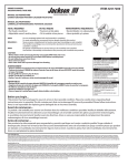
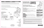
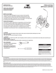
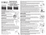
ITEM #2397200
OWNER’S MANUAL
SWIVEL METAL WALL
MOUNT HOSE REEL
MANUAL DEL PROPIETARIO
Portamanguera metálico
y giratorio de pared
Before you begin...
This product has been packaged to assure it arrives in best possible
condition. Please be careful when unpacking. Read instructions prior
to assembly. This kit contains parts that can be damaged if incorrectly
assembled. Please follow instructions. Ames® is not responsible for replacing
parts damaged due to incorrect assembly.
Antes de comenzar ...
Este producto ha sido empacado para resguardarlo y permitir que llegue
en la mejor condición posible. Tenga cuidado al desempacarlo. Sírvase leer
el manual de instrucciones detenidamente antes de ensamblar. Este juego
contiene piezas que pueden ser dañadas si ensambladas incorrectamente.
Siga las instrucciones. Cuando las piezas han sido ensambladas
incorrectamente, Ames® no reemplazará las piezas dañadas.
NOTE:
NOTA: Do not completely tighten bolts until assembly is completed.
For easier assembly, we recommend that two people assemble this product.
No apriete completamente los pernos hasta que el ensamblaje esté completo.
Para facilitar el ensamblaje, recomendamos dos personas para ensamblar este producto.
⚠CAUTION
Please consider carefully the appropriate method to be used in mounting this hose reel. Hardware is included for
your convenience, but may not be suitable for all mounting conditions. Some surfaces like vinyl siding or stucco
may require special considerations or additional hardware. Improper mounting can cause personal injury or
property damage. If you are unsure, contact a home improvement professional.
⚠PRECAUCIÓN
Favor de considerar cuidadosamente el método adecuado para el montaje de este portamanguera. Se incluye la
tornillería para el montaje pero puede no ser apropiada para todas las condiciones de montaje. Algunas superficies
como las coberturas de vinilo o estuco pueden requerir consideraciones especiales o tornillería adicional. Un
montaje inadecuado puede causar lesiones o daños a la propiedad. Si no está seguro, contacte a un profesional
en instalaciones.
⚠WARNING
This product contains chemicals known to the State
of California to cause cancer and birth defects or
other reproductive harm. DO NOT place your hands
in your mouth after handling the product. DO NOT
place the product in your mouth. DO NOT drink
water from the hose. WASH HANDS AFTER USE.
⚠ADVERTENCIA
Este artículo contiene productos químicos reconocidos por el Estado de California como causante de
cáncer, defectos de nacimiento u otros daños del
sistema reproductivo. NO coloque las manos en
la boca después de utilizar el artículo. NO coloque
el artículo en la boca. NO beba el agua de esta
manguera. LÁVESE LAS MANOS DESPUÉS DEL USO.
TOOLS REQUIRED
Powered Hand Drill or Hammer Drill with 3/8” (10mm) Masonry Drill Bit
or 1/4”(6mm) Standard Drill Bit
Small Hammer or Mallet
#3 Phillips Screwdriver
HERRAMIENTAS REQUERIDAS
Taladro eléctrico o taladro percutor con broca para concreto de 10 mm
(3/8 pulg.) o broca estándar de 6 mm (1/4 pulg.)
Martillo o mazo pequeño
Destornillador Phillips #3
5 Year Limited Warranty
Ames® warrants to the original purchaser only of the accompanying product that such product will be free from defects in material and workmanship for 5 years from the date of purchase. In the event of any such defect in material or workmanship, Ames®
will provide a replacement product at no charge if the product is returned to its place of purchase or to Ames® at 465 Railroad Avenue. Camp Hill, PA 17001. Damage to the product caused by accident, misuse, abuse, unauthorized repair, or use in other than
normal home or personal use or private non commercial use, is not covered by this limited warranty. Ames® shall not be liable for incidental or consequential damages, for breach of any express or implied warranty, but some states do not allow the exclusion or
limitation of incidental or consequential damages, so to the extent that they do not, the above limitation may not apply to you. This warranty gives you specific legal rights and you may have other specific legal rights which vary from state to state.
Garantía limitada de 5 años
Ames® garantiza este producto solamente al comprador original por medio de la presente, contra defectos en los materiales o en la mano de obra, por un período de 5 años, después de la fecha de compra. En caso de que haya defectos en los materiales o en la
mano de obra, Ames® proporcionará un producto de reemplazo sin costo, si devuelve el producto al detallista o a Ames®, 465 Railroad Avenue, Camp Hill, PA 17011. Los daños al producto, debidos a un accidente, utilización inadecuada, abuso, reparaciones no
autorizadas o una utilización diferente a la utilización doméstica común o personal o una utilización que no sea comercial privada, no están cubiertos en esta garantía. Ames® no será responsable por los daños incidentales o indirectos, o violaciones a cualquier
garantía expresa o implicita. Algunos estados no permiten la exclusión o la limitación de daños incidentales o indirectos, así como la exclusión de la limitación que se encuentra arriba, puede ser que ésto no se le aplique a Ud. Esta garantía le otorga derechos
legales específicos y Ud. puede tener otros derechos que varían de estado en estado.
©2014 The AMES Companies, Inc. GR4262
For replacement parts, contact:
Pour obtenir des pièces de rechange, veuillez contacter :
5
IN THE US: EN EE. UU.:
Ames
465 Railroad Ave.
Camp Hill, PA 17011
1-800-393-1846
www.ames.com
4
IN CANADA:
En CANADÁ:
Garant
375, Chemin Saint-Francois Ouest
Saint-François (Québec)
G0R 3A0, Canada
1-800-463-7040
1
3
Description
IN Mexico:
En México:
Alta Tensión No 98 Local 15
Colonia Molino de Rosas
Del. Alvaro Obregon
México, Distrito Federal
C.P. 01470
01-800-400-2886
Give P/N and Description when ordering parts.
Mencione el número y descripción de la pieza al ordonar.
2
Item
ART.
ART.
QTY
QUANT
CANT.
DESCRIPCIÓN
1
1
Leader Hose
Extensión de manguera
2
1
Hardware Pack
Paquete de ferretería
3
1
Crank Knob
Botón de manivela
4
1
Inlet Tube with Seals
Tubería de entrada con sellos
RD-HSE-03205
5
1
Locking Lever
Palanca de cierre
RD-HSE-03263
-
4
Lag Screws
Tornillos largos
–––
-
1
Anchors
Anclajes
–––
MAINTENANCE:
Part Number
NUMÉRO DE
PIÈCE
NÚMERO DE PIEZA
2517103
RD-HSE-05624
05677
Other components may be identified by part
numbers marked on the part.
Anchors for masonry application only.
Lift and twist to disengage lock.
Otros componentes pueden estar identificados
con un número en la pieza.
Los anclajes son sólo para aplicarlos sobre
concreto.
Levante y gire para liberar el seguro.
MANTENIMIENTO:
Annual Seal Lubrication
To prevent leaks and to lengthen seal life, the water inlet seals should be lubricated
annually. Reference Figure 1.
• Stop the flow of water to the unit by shutting the faucet valve.
• Release locking lever.
• Pull the inlet tube from the frame of the unit.
• Lubricate the seals as indicated. Any white lithium spray lubricant is recommended.
• Replace the inlet tube and close the locking lever.
Winter Preparation
To prevent damage from expanding ice, always disconnect and drain all hoses prior to
freezing conditions.
Lubricación anual de los sellos
Para evitar fugas y extender su vida útil, los sellos de la tubería de entrada de agua
deben lubricarse anualmente. Ver Figura 1.
• Detenga el flujo de agua a la unidad cerrando el grifo.
• Libere la palanca del cierre.
• Tire de la tubería de entrada para desconectarla de la unidad.
• Lubrique los sellos como se indica. Se recomienda usar cualquier lubricante
atomizado de litio blanco.
• Coloque nuevamente la tubería de entrada y cierre la palanca.
Preparación para el invierno
Para evitar los daños por la expansión del hielo, siempre desconecte y drene todas las
mangueras antes que se produzcan condiciones de congelación.
©2014 The AMES Companies, Inc. GR4262
Figure 1
Figura 1
ASSEMBLY:
ENSAMBLAJE:
Attaching the Crank Knob
Fijación del botón de manivela
Tools Required:
#3 Phillips Screwdriver
Instructions:
• Place Crank Knob over its mounting. Reference Figure 2.
• Secure in place using screw provided.
Herramientas requeridas:
Destornillador Phillips #3
Instrucciones:
• Coloque el botón de manivela sobre su base. Ver Figura 2.
• Fíjelo en su lugar con el tornillo incluido.
Figure 2
Figura 2
Attaching the Leader Hose
Fijación del botón de manivela
Instructions:
• Remove leader hose from the reel.
• Verify placement of rubber washers in leader hose couplings.
• Install one end of the leader hose to the water inlet tightening the threaded
coupling by hand. Reference Figure 3.
Instrucciones:
• Retire la extensión de manguera del carrete.
• Verifique la colocación de las arandelas de hule en los acoplamientos de la
extensión de manguera.
• Instale un extremo de la extensión de manguera a la entrada de agua apretando la
rosca del acoplamiento con la mano. Ver Figura 3.
Figure 3
Figura 3
INSTALLATION:
INSTALACIÓN:
Mounting to Concrete or Brick Masonry Construction
Montaje sobre construcción de concreto o ladrillo
Tools Required:
#3 Phillips Screwdriver
Powered Hand Drill or Hammer Drill with 3/8” (10mm) Masonry Drill Bit
Small Hammer or Mallet
Instructions:
• Determine the mounting hole locations using the mounting template
provided on the product carton.
• Drill four (4) holes 2” (50mm) deep.
• Insert masonry anchors provided into each hole. These may need to be
seated by taping tapping with a mallet. Reference Figure 4.
• Open the locking hinge and lock in a position that allows access to the mounting brackets.
Herramientas requeridas:
Destornillador Phillips #3
Taladro eléctrico o taladro percutor con broca para concreto de 10 mm (3/8 pulg.)
Martillo o mazo pequeño
Instrucciones:
• Determine la ubicación de los orificios utilizando la plantilla de montaje incluida en el cartón del producto.
• Taladre cuatro (4) orificios de 50 mm (2 pulg.) de profundidad.
• Inserte los anclajes para concreto incluidos en cada orificio. Puede que necesite asentarlos bien golpeándolos
suavemente con un mazo. Ver Figura 4.
• Abra el cierre de bisagra y colóquelo en una posición que le permita el acceso a los soportes.
• Coloque la unidad sobre los anclajes y asegúrela con los tornillos largos incluidos en cada anclaje. Verifique que el
botón del cierre esté orientado hacia arriba para garantizar un funcionamiento adecuado.
Figure 4
Figura 4
©2014 The AMES Companies, Inc. GR4262
INSTALLATION (cont.):
INSTALACIÓN (A CONTINUACIÓN):
Mounting to Flat Wood Frame Construction
Montaje sobre construcción de madera plana
Tools Required:
#3 Phillips Screwdriver
Powered Hand Drill with 1/4”(6mm) Standard Drill Bit
Instructions:
• Determine the mounting hole locations using the mounting template provided
on the product carton.
⚠CAUTION - To prevent damage or injury, be sure to verify that holes align with
stud locations in the wall.
• Drill four (4) holes 2” (50mm) deep.
• Locate unit over holes and secure with lag screws provided. Reference Figure 5.
Herramientas requeridas:
Destornillador Phillips #3
Taladro eléctrico con broca estándar de 6 mm (1/4 pulg.)
Instrucciones:
• Determine la ubicación de los orificios para el montaje utilizando la plantilla de
montaje incluida en el cartón del producto..
Figure 5
Figura 5
⚠PRECAUCIÓN - Para evitar daños o lesiones, asegúrese de verificar que los
orificios estén alineados con la posición de los montantes de pared.
• Taladre cuatro (4) orificios de 50 mm (2 pulg.) de profundidad.
• Coloque la unidad sobre los orificios y asegúrela con los tornillos largos incluidos.
Ver Figura 5.
OPERATION:
OPERACIÓN:
Using the Swivel Function
• This unit is designed with a locking hinge that allows you to reorient the
reel as needed.
• Simply lift the locking knob as seen in Figure 6 to release the lock. This will allow you to
rotate the reel to the next locking position. The hinge will automatically lock in the new
position.
• By lifting the locking knob and turning counter-clockwise, the lock is disengaged
completely. This allows the unit to freely rotate.
• To re-engage the lock, lift the locking knob once again and rotate clockwise. The unit will
lock in the next locking position.
Uso de la función giratoria
• Esta unidad está diseñada con un cierre de bisagra que le permite reorientar el carrete
según lo necesite.
• Sencillamente levante el botón del cierre como se observa en la Figura 6 para liberar el
cierre. Ésto le permitirá rotar el carrete hasta que caiga en la próxima posición. La bisagra
trancará automáticamente en la nueva posición.
• Levante el botón del cierre y gírelo en contra de las manecillas del reloj para liberar el
cierre completamente. Ésto permite a la unidad girar libremente.
• Para activar nuevamente el cierre, levante el botón del cierre una vez más y gírelo a favor
de las manecillas del reloj. La unidad caerá en la próxima posición.
©2014 The AMES Companies, Inc. GR4262
Figure 6
Figura 6