1
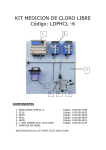
Manual de Instrucciones (Cód. 136312) POOL CONTROLLER/3 pH – Clorine PC95 Medidor y regulador, con microprocesador pH – Cloro – temperatura 90 l/h 80 l/h 70 l/h 60 l/h 50 l/h 40 l/h 30 l/h 20 l/h 10 l/h Ingresso campione acqua (1/2" Gf) > 20 l/h Manuale Versione 1.1 NOTAS DE PRECAUCIÓN PARA EL INSTALADOR Antes de efectuar la instalación o el mantenimiento del Pool Top, cortar la tensión de alimentación. Comprobar que la tensión de alimentación se corresponda con la indicada en la placa situada en el instrumento PC95. El incumplimiento de una de las prescripciones aquí presentadas puede acarrear daños a personas y cosas, como también puede conllevar un funcionamiento erróneo y daños a piezas. Para la instalación proceder como indicado a continuación: 1) 2) 3) 4) 5) Colocar el panel mural a una altura que facilite el acceso, tanto a la parte inferior como a la parte superior del panel. N.B. El panel se debe emplazar a nivel y a ser posible a plomo. Dejar libre el pavimento a fin de facilitar el acceso al panel. Conectar la entrada del agua a una toma que garantice, sin interrupciones, un caudal de agua entre 40 y 60 l/h con una presión igual que la contrapresión de salida + 0,5 bar; dicha presión se aconseja que no supere los 3 bar. El caudal se debe mantener constante; eventuales variaciones causan un error en la medida evaluable en un 1,5%/∆ l/h. Si faltando alimentación el tubo de impulsión se puede vaciar, se aconseja instalar una válvula de flujo simple en la entrada. De esta manera se evita que se vacíe la pileta portaelectrodos por efecto sifón, tratándose de una situación que perjudica el electrodo de medida del pH. Conectar la salida con un punto para recuperar el agua, con una contrapresión a lo sumo de 2 bar. Montar el electrodo pH en la pileta correspondiente y abrir la válvula en la entrada del panel. Ajustar la válvula a fin de conseguir un caudal de ≅ 60 l/h. 2 LISTA DE IDENTIFICACIÓN DE LAS PARTES DESCRIPCIÓN DE LAS PARTES 90 l/h 80 l/h 70 l/h 60 l/h 50 l/h 40 l/h 30 l/h 20 l/h 10 l/h Ingresso campione acqua (1/2" Gf) > 20 l/h A B pH4 C pH7 D 2 HO E G F H I LISTA DE IDENTIFICACIÓN DE LAS PARTES Ø 14 A B C D E F G H I Electrodos pH Sonda temperatura PT100 (Opción) Pernos para la fijación mural del panel Kit soluciones tampón 4pH, 7pH, H2O, 465mV Kit DPD Cepillo Bolitas de vidrio Anillo fijación sonda. LLAVE PARA EL VASO DEL FILTRO Y DEL PORTASONDAS 13 Ø 14 3 DESCRIPCIÓN DE LAS PARTES 1) 2) 3) 4) 5) 6) 7) 8) 9) 10) 11) 12) 13) 14) 15) 16) 17) 18) Instrumento PC 95 Válvula de regulación del caudal Sonda Temperatura Sonda pH Electroválvula Soporte panel Desagüe 4X6 Sonda Cloro Grifo de sangrado y vaciado sonda cloro Entrada muestra agua 4X6 Sensor de flujo Caudalímetro graduado Filtro Tapa de protección Bolsillo multiuso Alimentación bomba ph Alimentación bomba cloro Alimentación instrumento PC 95 DATOS TÉCNICOS Panel Medidas: Peso: Entrada muestra: Salida muestra: Regulador de caudal: Alarma flujo: Célula de medida del cloro TECNOLOGÍA: ELECTRODOS: LIMPIEZA: CALIBRACIÓN: (A x L x P) 600 x 700 x 10 mm 8 Kgr 4X6 4X6 de área variable 5 l/h 60 l/h contacto reed ausencia flujo AMPERIMÉTRICA AUTOLIMPIANTE PLATINO – COBRE CON 200 BOLITAS DE VIDRIO semiautomática con comparación de DPD Medida del pH Electrodo: SPH-1-S-1,5 0..14pH 3 BAR 60 °C Instrumento electrónico Modelo: PC95 Medidas: pH 0..14, Cloro 0…5 ppm, °C 0..125 Regulaciones: On/Off, pausa/trabajo, proporcional por impulsos, proporcional en corriente Salidas: relé/ mA/ impulsos Calibración: autocalibración pH, Cloro Alimentación: standard 230 ± 10% 50 60 Hz Accesorios Soluciones pH: 7.00, 4.00 pH a 20 °C 90ml Opción Sensor de la temperatura: PT100 en vidrio 12*160mm 4 PARTE ELECTRICA Quitar la tapa de protección. Conectar la bomba de regulación de pH se conecta a los contactos PH PUMP 90 l/h 80 l/h 70 l/h 60 l/h 50 l/h 40 l/h 30 l/h 20 l/h 10 l/h Ingresso campione acqua (1/2" Gf) > 20 l/h Conectar la bomba de regulación de CL se conecta a los contactos CL PUMP ATENCIÓN No colocar los bidones que contienen sustancias químicas debajo del POOL STAR, las exhalaciones generadas causan un deterioro de los equipos. La distancia aconsejada es de 2 mt. ATENCIÓN ATTENZIONE / WARNING 2 mt 90 l/h 80 l/h 70 l/h 60 l/h 50 l/h 40 l/h 30 l/h 20 l/h 10 l/h Ingres so campione acqua (1/ 2" Gf) > 20 l/h SERBATOI TANKS NOTAS: Para la calibración de las sondas, la conexión de las bombas dosificadoras y su utilización, se remite a la lectura del MANUAL DE INSTRUCCIONES PARA EL INSTALADOR del PC95. 5 Mantenimiento y limpieza sonda Cloro Cuidado con no hacer caer las bolitas de vidrio contenidas dentro de la sonda. Efectuar las siguientes operaciones: 1. 2. 3. 4. Cerrar el flujo del agua Abrir el grifo de sangrado para descargar el circuito. Desenroscar la sonda pH para facilitar el vaciado del circuito. Cuando el circuito está vacío, desenroscar y sacar la sonda cloro, prestar suma atención en no hacer caer las bolitas de vidrio. Limpieza del electrodo de Cobre: 1. 2. Desconectar el faston (conexión electrodo Platino) Desenroscar el electrodo Prestar atención en no modificar la medida de la espira de platino, guardarla en un sitio seguro. Frotar el electrodo de cobre con el cepillo incluido en el suministro hasta dejar brillante el electrodo. Terminada la operación montar de nuevo las partes prestando atención en no doblar el electrodo de platino. Cambio bolas de vidrio. Para cambiar las bolas de viario efectuar las siguientes operaciones: 1. 2. 3. Mojar con agua las bolas incluidas en el suministro Utilizar un destornillador con punta plana para ponerlas dentro de la sonda. Al final de las operaciones cerrar la sonda en todas sus partes. 6 7 Instruction Manual (Cod. 136312) POOL CONTROLLER/3 pH – Clorine PC95 Microprocessor measuring and regulating unit pH – Chlorine – Temperature 90 l/h 80 l/h 70 l/h 60 l/h 50 l/h 40 l/h 30 l/h 20 l/h 10 l/h Ingresso campione acqua (1/2" Gf) > 20 l/h Manual Version 1.1 PRECAUTIONARY NOTES FOR THE INSTALLER Before installing or carrying out maintenance on the pool top disconnect the electrical power supply. Check that the power supply voltage coincides with that indicated on the plate on the PC95 instrument. Failure to abide by the instructions given here may result in harm to people or damage to property, as well as the incorrect functioning and damaging of component parts. To install the unit, proceed as follows: 1) 2) 3) 4) 5) Mount the panel on a wall at a height above ground level that makes both the bottom and the top of the panel easily accessible. N.B. The panel must be positioned level and upright where possible. Leave the floor below the unit uncluttered to make the panel easily accessible. Connect the water intake to an inlet that guarantees an uninterrupted flow of water of between 40 and 60 litres / hour, at a pressure that is equal to the outlet back-pressure +0,5 bar. This pressure should not exceed 3 bar. The flow rate is to remain constant, as any fluctuations will cause an error in measurement equal to 1,5%/ǻ lit/h. If the delivery pipe is liable to empty in case of a power failure, it is advisable to fit a non-return valve at the intake. This will prevent the tub that contains the siphoning electrodes from emptying, which would damage the pH-measuring electrode. Connect the outlet to a point at which water is recovered, with a maximum back-pressure of 2 bar. Fit the pH electrode in the relevant tub and open the valve at the intake to the panel. Adjust this valve to produce a flow rate of # 40 lit/h. 2 PARTS IDENTIFICATION LIST PARTS DESCRIPTION 90 l/h 80 l/h 70 l/h 60 l/h 50 l/h 40 l/h 30 l/h 20 l/h 10 l/h Ingresso campione acqua (1/2" Gf) > 20 l/h A B pH4 C pH7 2 HO D E G F H I PARTS IDENTIFICATION LIST 14 A B C D E F G H I pH Electrode PT100 temperature probe (Optional) Rawl bolts for fixing the panel to the wall. Buffer solution kit 4pH, 7pH, H2O, 465mV DPD Kit Brush Glass spheres Probe clamp Filter Spanner 13 14 3 1) 2) 3) 4) 5) 6) 7) 8) 9) 10) 11) 12) 13) 14) 15) 16) 17) 18) PARTS DESCRIPTION PC 95 Instrument Flow regulating valve Temperature Probe pH Probe Solenoid valve Panel Support 4X6 Water Outlet Chlorine probe Drawing off tap and chlorine probe outlet 4X6 Water sample intake Flow sensor Graduated flow meter Filter Channel Tool holder pocket Cable for pH pump Cable for Chlorine pump Power supply cable for the PC95 instrument. TECHNICAL DATA Panel Dimensions: Weight: Sample intake: Sample outlet: Flow regulator: Flow alarm: Chlorine measuring cell TECHNOLOGY: ELECTRODES: CLEANING: CALIBRATION: (H x W x D) 600 x 700 x 10 mm 8 kg 4X6 4X6 with variable area 5 lit/h, 60 lit/h reed contact in absence of flow SELF-CLEANING AMPEROMETRIC PLATINUM - COPPER WITH 200 GLASS SPHERES semi-automatic, with DPD comparison pH Measurement Electrode: SPH-1-S-1,5 0..14pH 3 BAR 60 °C Electronic instrument Model: PC95 Measurement: Ph 0..14, Chlorine 0…5 ppm, °C 0..125 Regulation: On/Off, Standby/Work, impulse proportional, current proportional Outputs: relay/ mA/ impulses Calibration: pH, Chlorine, self calibrating Power Supply: standard 230V ± 10% 50-60 Hz Accessories pH Solutions: 7.00, 4.00 pH at 20 °C 90ml Optional Extra Temperature sensor: PT100 in glass 12*160mm 4 ELECTRICAL CONNECTION Open the protective cover. Connect the pH regulation pump to the PH PUMP contacts. Connect the chlorine regulation pump to the CL PUMP contacts. WARNING Do not place bins containing chemical substances below the POOL STAR, as fumes emitted will damage the equipment. The recommended clearance is 2 m. ATTENZIONE / WARNING 2 mt 90 l/h 80 l/h 70 l/h 60 l/h 50 l/h 40 l/h 30 l/h 20 l/h 10 l/h Ingres so campione acqua (1/ 2" Gf) > 20 l/h SERBATOI TANKS NOTE: For setting the probes and connecting up the dosage pumps and using the same, please read the INSTALLER’S INSTRUCTION MANUAL for the PC95. 5 Maintenance and cleaning of the Chlorine probe Be careful not to drop the glass balls inside the probe. Proceed as follows: 1. 2. 3. 4. Stop the flow of water. Open the drawing off tap to drain the circuit. Unscrew the ph probe to facilitate emptying of the circuit. When the circuit is empty unscrew the chlorine probe and remove it. Be very careful not to drop the glass balls. Cleaning the Copper electrode: 1. 2. Unclip the faston clip (Platinum electrode connection) Unscrew the electrode. Be careful not to change the dimensions of the platinum spiral. Keep it in a safe place. Brush the copper electrode off, using the brush provided until it is shiny. Once this has been done refit the parts being careful not to bend the platinum electrode. Replacing the glass balls. Proceed as follows to replace the glass balls: 1. 2. 3. Soak the balls supplied with water. Use a straight screwdriver to position them inside the probe. When complete, close all parts of the probe again. 6 7