1
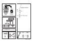
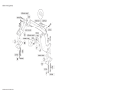
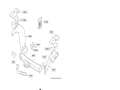
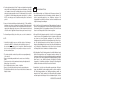
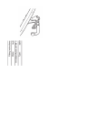
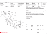
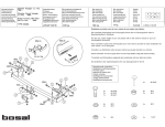
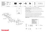
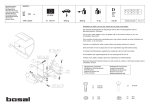
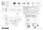
Make:
3195
quality
linked to
Permanently
Type:
Rezzo; 2000->
Tacuma/Vivant; 2000->
Chevrolet/Daewoo
Fitting instructions
Couplingsclass: A50-X
euro
tested
Approved
M10
17
46 Nm
M12
19
79 Nm 71 Nm(self-locking)
Approved
Approved
94/20/EC
e11 00-3072
Max. mass trailer : 1500 kg
Max. vertical load : 75 kg
D-Value: 8,2 kN
8.8
8
1000km
0km
+
© 319570/19-02-2008/1
© 319570/19-02-2008/14
© 319570/19-02-2008/13
© 319570/19-02-2008/2
© 319570/19-02-2008/3
Dispositivo di traino tipo:
Per autoveicoli:
Tipo funzionale:
Brink 3195
Daewoo Tacuma (U100);2000->
Classe e tipo di attacco:
A50-X
Approvazione N.:
e11 00-3072
Valore D:
8,2 kN
Carico max. verticale S:
75 kg
Larghezza rimorchiabile per Caravan e T.A.T.S.: 2,45m vedere CARTA di CIRCOLAZIONE VEICOLO (motrice) + 70 cm = ..arrotondare ai 5 cm
superiore (vedi D.M.28/05/85)
Massa rimorchiabile:
vedi carta di circolazione dell’ autoveicolo
Per verificare l’idoneità del dispositivo di traino omologato a norma
CEE 94/20, all’installazione sulla vettura su cui si intende procedere al montaggio, compilare la seguente formula (se necessario
declassare la massa rimorchiabile):
≤ 8,2kN
dove: T= Massa Complessiva Max. della motrice (in kg)
C= Massa Rimorchiabile Max. della motrice (in kg)
DA COMPILARE PER IL COLLAUDO
DICHIARAZIONE DI CORRETTO MONTAGGIO: la sottoscritta Ditta dichiara di aver montato in maniera corretta ed in conformit⁄ alle prescrizioni sia del costruttore del veicolo che del costruttore del dispositivo stesso il seguente dispositivo di attacco meccanico:
tipo:..........................................................................................
Il dispositivo di attacco sopra indicato è stato installato su autoveicolo
modello:...................................................................................
targa:........................................................................................
Data:.........................................................................................
TIMBRO e FIRMA
Si dichiara inoltre di aver informato l’utente del veicolo sull’USO e MANUTENZIONE del dispositivo stesso.
© 319570/19-02-2008/12
fig. 1
© 319570/19-02-2008/11
NL
MONTAGEHANDLEIDING:
1. Verwijder de vloerbedekking van de bodemvloer in de kofferbak.
Verwijder eveneens het kunststofachterpaneel en de beide zijpanelen.
Verwijder de beide bagage-sjorogen van de bodemvloer. Plaats de contraplaten A en B met de gaten C op draadgaten van de bagage-sjorogen.
2. Boor de gaten D + K ø11mm door de bodemvloer. Attentie let er op dat
de contraplaten in lijn met het chassis en parrallel met elkaar lopen.
Verwijder de contraplaten. Vergroot de gaten D aan de bovenzijde in het
chassis tot ø18mm.
3. Steek de twee M10x120 bouten door de gaten D in de contra’s A en B.
Schuif de afstandsbussen over de draadeinden en plaats het geheel op
de bovenvloer. Steek de twee M10x110 bouten en de twee M10x120
bouten door de gaten K. Bevestig t.p.v. de punten C de bagage sjorogen. Laat de achterste uitlaatdemper zakken. Verwijder het hitteschild.
Schuif de overige vier afstandsbussen via de gaten K onderzijde chassis over de draadeinden van de bouten.
4. Plaats de bevestigingsplaten E en F en zet deze handvast d.m.v. zes
moeren M10 inclusief veer- en sluitringen. Plaats de dwarsbalk tussen
de gemonteerde bevestigingsplaten en bevestig deze handvast d.m.v
het in de schets genoemde bevestigingsmateriaal. Bevestig t.p.v. punt
G één bout M12x110 inclusief veerring, contraplaatje I,J en moer. Let
op ! de sleepogen bevinden zich tussen de plaatjes I en J en t.p.v. punt
H.
5. Zaag overeenkomstig fig.1 een deel van het hitteschild.Monteer de
kogelstang inclusief stekkerplaat overeenkomstig de schets. Draai alle
bevestigingsbouten van de trekhaak overeenkomstig de tabel vast.
Herplaats het hitteschild en hang de uitlaat terug. Zaag, indien nodig,
de hoeken van de zijpanelen uit t.p.v. de punten D en K. Herplaats het
onder punt 1 verwijderde.
Raadpleeg voor demontage en montage van voertuig onderdelen het
werkplaats handboek.
BELANGRIJK:
* Voor eventueel noodzakelijke aanpassing(en) “van het voertuig” dient
men de dealer te raadplegen.
* Indien op de bevestigingspunten een bitumen of anti-dreunlaag aanwezig is, dient deze verwijderd te worden.
* Voor de max. toegestane massa, welke uw auto mag trekken, dient u uw
dealer te raadplegen.
* Bij het boren dient men er zorg voor te dragen, dat electriciteits-, rem- en
brandstofleidingen niet worden geraakt.
* Verwijder "indien aanwezig" de plastik dopjes uit de puntlasmoeren.
* Deze handleiding dient na montage bij de voertuigpapieren gevoegd te
worden.
GB
FITTING INSTRUCTIONS:
1. Remove the floor covering from the bottom of the boot. Also remove the
plastic rear panel and both side panels. Remove both luggage towing
brackets from the floor. Position back plates A and B with holes C lining
up with the threaded holes of the luggage towing brackets.
2. Drill holes D and K ø11 mm through the floor. Warning: Make sure the
back plates are positioned in line with the chassis and parallel with one
another. Remove the back plates. Enlarge the holes D on the top side
of the chassis to ø18 mm.
3. Put M10x120 bolts through the holes D in back plates A and B. Slide the
spacers onto the threaded ends and place all of this on the floor. Put
two M10x110 bolts and two M10x120 bolts through the holes K. Attach
the luggage towing brackets at points C. Allow the last exhaust silencer
to drop down. Remove the heat shield. Via the holes K in the underside
of the chassis, slide the four spacers over the threaded ends of the
bolts.
© 319570/19-02-2008/4
4. Put the attachment plates E and F in place and attach them hand-tight
using six M10 nuts including spring washers and flat washers. Place the
cross member between the mounting plates and fasten it hand-tight
using the fastening materials referred to in the drawing. Fasten at point
G one M12x110 bolt including spring washer, back plates I, J, and nut.
NOTE: the towing eyes are located between the plates I and J and at
point H.
5. Saw out of the heat shield the portion indicated in fig. 1. Fit the ball hitch,
including socket plate, as shown in the drawing. Tighten all nuts and
bolts to the torque stated in the table. Reattach the heat shield and resuspend the exhaust pipe. Saw corners off the side panels at the heads
of bolts D and K, if applicable. Reattach those parts removed in step 1.
For dismantling and fitting the vehicle parts, see the site handbook.
NOTE:
* Should this installation process entail the cutting of the bumper –
conformation MUST be obtained by the installation engineer of
the customer’s acceptance prior to completion. Brink International
do not accept responsibility for any matters arising as a result of
this miscommunication.
* The dealer should be consulted for possible necessary adjustment(s)
"of the vehicle".
* Remove the insulating material from the contact area of the fitting
points.
* Consult your dealer for the maximum tolerated pull weight and ball
hitch pressure of your vehicle.
* Do not drill through electrical-, brake- or fuellines.
* Remove (if present) the plastic caps from the spot welding nuts.
* This fitting instruction has to be enclosed in the vehicle documents after
fitting the towbar.
D
MONTAGEANLEITUNG
1. Den Fußbodenbelag vom Fußboden im Kofferraum entfernen. Die
Kunststoffrückwand und beide Seitenwände ebenfalls entfernen. Die
beiden Gepäcksicherungsösen vom Fußboden entfernen. Die
Gegenplatten A und B mit den Löchern C auf den Gewindelöchern der
Gepäcksicherungsösen anbringen.
2. Die Löcher D und K ø11 mm durch den Fußboden bohren. Darauf achten, dass die Gegenplatten in einer Linie mit dem Fahrgestell und parallel zueinander laufen. Die Gegenplatten entfernen. Die Löcher D an der
Oberseite des Fahrgestells bis auf ø18 mm vergrößern.
3. Die zwei M10x120-Schrauben durch die Löcher D in die Gegenplatten
A und B stecken. Die Distanzhülsen über die Gewinde schieben und
das Ganze auf dem Fußboden anbringen. Die zwei M10x110Schrauben und die zwei M10x120-Schrauben durch die Löcher K stecken. Die Gepäcksicherungsösen bei den Punkten C befestigen. Den
hintersten Auspuffdämpfer runter lassen. Das Hitzeschild abmontierenen. Die übrigen vier Distanzhülsen via die Löcher K an der Unterseite
des Fahrgestells über die Gewinde der Schrauben schieben.
4. Die Halteplatten E und F anbringen und mit sechs M10-Muttern einschließlich Unterlegscheiben und Federringen handfest anziehen. Die
Querstange zwischen die montierten Halteplatten anbringen und handfest mit dem in der Skizze genannten Befestigungsmaterial befestigen.
Beim Punkt G eine M12x110-Schraube einschließlich Federring,
Gegenplatte I, J und Mutter befestigen. Achtung! Die Abschleppösen
befinden sich zwischen den Platten I und J beim Punkt H.
5. Gemäß Abb. 1 ein Stück des Hitzeschildes ausschneiden. Die Kugelstange einschließlich Steckdosenplatte gemäß der Skizze montieren.
Alle Befestigungsschrauben der Anhängervorrichtung gemäß der
Angaben in der Tabelle anziehen. Das Hitzeschild wieder anbringen
und den Auspuff zurück hängen. Bei den Schraubenköpfen D, K even-
© 319570/19-02-2008/5
tworzywa sztucznego oraz obydwie ścianki boczne. Usunąć z podłogi
bagażnika uchwyty mocujące bagaż. Płyty kontrujące A i B przyłożyć
otworami C do otworów uchwytów mocujących bagaż.
2. Otwory D i K o średnicy 11mm przewiercić przez podłogę. Należy
uważać, aby płyty kontrujące znajdowały się w jednej linii z podwoziem
i równolegle względem siebie. Zdjąć płyty kontrujące. Otwory D od
górnej strony podwozia powiększyć do średnicy 18mm.
3. Przez otwory D wsunąć w płyty kontrujące A i B dwie śruby M10x120.
Przez gwint wsunąć tulejki dystansowe, a następnie całość przykręcić
do podłogi. Przez otwory K umieścić dwie śruby M10x110 i dwie śruby
M10x120. Uchwyty mocujące bagaż przykręcić w punktach C. Tylny
tłumik opuścić. Odkręcić osłonę cieplną. Pozostałe tulejki dystansowe
wsunąć w otwory K na spodniej stronie podwozia poprzez gwinty śrub
M10x120.
Wskazówki:
- Po przejechaniu 1000 km dokręcić wszystkie elementy skręcane.
- Podczas ewentualnych odwiertów upewnić się czy w pobliżu nie znajdują się przewody instalacji elektrycznej, przewody hydrauliczne lub
przewody paliwowe.
- Wszystkie ubytki powłoki lakierniczej zabezpieczyć przed korozją.
- Należy wyjąć ewentualne plastikowe zaślepki w punktach przyspawanych nakrętek.
- Stosować nakrętki oraz śruby gatunkowe dostarczone w komplecie.
- Utrzymywać kulę w czystości, oraz pamiętać o regularnym jej smarowaniu.
- Hak holowniczy zarejestrować w stacji diagnostycznej.
Zastosowanie się do powyższych wskazań gwarantuje Państwu bezpieczeństwo, niezawodność i sprawność naszego wyrobu przez cały okres
jego użytkowania.
4. Płyty mocujące E i F przyłożyć , a następnie przykręcić sześcioma
nakrętkami M10 wraz z podkładkami płaskimi i sprężynowymi. Belkę
poprzeczną umieścić pomiędzy zamontowanymi płytami mocującymi ,
a zamontować za pomocą elementów mocujących wymienionych na
rysunku. W punkcie G przykręcić śrubę M12x110 wraz z podkładką
sprężynową, płytą kontrującą I, J oraz nakrętką. Uwaga! Uchwyty
holownicze znajdują się pomiędzy płytami I i J w punkcie H.
5. Według rysunku 1. wyciąć element z osłony cieplnej. Kulę haka holowniczego wraz z podstawą pod gniazdo zamontować według rysunku.
Wszystkie śruby i nakrętki dokręcić według danych z tabeli. Ponownie
zamontować osłonę cieplną oraz zawiesić wydech. Przy głowach śrub
D, K wyciąć ewentualne kanty ze ściany bocznej. Elementy zdemontowane w punkcie 1 ponownie zamontować.
Co do montażu i montowania części pojazdu zapoznać się z
podręcznikiem warsztatowym.
© 319570/19-02-2008/10
N.B.:
* Para (una) eventual(es) adaptación(es) 'del vehículo' consúltese al
concesionario.
* Si en los puntos de fijación hay una capa de betún o anti-choque hay
que quitarla.
* Consulte a su concesionario para el peso máximo de tracción y la presión de la bola admitida de su vehículo.
* No agujerear cable de eléctrico, tubos de freno o gasolina"
* Retirar, si presentes, los capuchones de plástico de las tuercas de soldadura por punto.
* Guarde estas instucciones junto a la documentación del veículo después del montaje del enganche.
I
ISTRUZIONI PER IL MONTAGGIO:
1. Rimuovere il rivestimento dal fondo del bagagliaio. Rimuovere il pannello di plastica posteriore ed entrambi i pannelli laterali. Rimuovere
entrambi gli anelli di assicurazione dei bagagli dal fondo del bagagliaio.
Posizionare le piastre di contrasto A e B con i fori C sui fori filettati lasciati liberi dagli anelli di assicurazione.
2. Praticare i fori D e K ø11 mm attraverso il fondo del bagagliaio.
Assicurarsi che le piastre di contrasto siano allineate con il telaio e siano
parallele tra di loro. Rimuovere le piastre di contrasto. Ingrandire i fori D
dal lato superiore, nel telaio, fino a ø18 mm.
3. Inserire i due bulloni M10x120 attraverso i fori D nelle contropiastre A e
B. Inserire le bussole sulle estremità filettate e posizionare il tutto sul
fondo del bagagliaio. Inserire i due bulloni M10x110 e due bulloni M10x
120 attraverso i fori K. Fissare gli anelli di assicurazione dei bagagli a
livello dei punti C. Lasciare scendere la parte posteriore del tubo di scarico. Rimuovere lo scudo termico. Inserire le restanti quattro bussole
sulle estremità filettate dei bulloni, passando attraverso i fori K sul lato
inferiore del telaio.
4. Posizionare i pannelli di fissaggio E ed F e fissarli avvitando manualmente sei dadi M10, completi di rondelle e rondelle elastiche.
Posizionare la staffa tra i pannelli di fissaggio così montati e fissarla
avvitando manualmente il materiale di fissaggio indicato nello schema.
Inserire un bullone M12x110, completo di rondella elastica, contropiastre I, J e dado, a livello del punto G. Attenzione! Gli anelli di traino sono
situati tra le piastrine I e J, a livello del punto H.
5. Segare via una parte dallo scudo termico, come indicato in fig. 1.
Montare l'asta della sfera, completa di piastra di contatto, come indicato nel disegno. Serrare tutti i bulloni di fissaggio del gancio traino alle
coppie di serraggio indicate in tabella. Rimontare lo scudo termico ed il
tubo di scarico. Eventualmente, segare via gli angoli dei pannelli laterali, dove questi toccano le teste dei bulloni D e K. Rimontare quanto
rimosso al punto 1.
Per lo smontaggio ed il montaggio dei componenti del veicolo consultare il manuale tecnico dell’officina.
N.B.:
* Per eventuali necessari adattamenti "del veicolo" si consiglia di consultare il fornitore.
* Rimuovere lo strato di materiale isolante dai punti d'attacco.
* Per il peso complessivo trainabile della Vostra vettura, consultate il
Vostro rivenditore autorizzato.
* Praticando i fori, prestare attenzione a non danneggiare i cavi elettrici, i
cavi del freno e i condotti del carburante.
* Rimuovere, se presenti, i coperchietti in plastica dai dadi di saldatura per
punto.
* Questa istruzione di montaggio deve essere allegata ai documenti del
veicolo dopo l'installazione del gancio.
PL
INSTRUKCJA MONTAŻOWA
1. Z bagażnika usunąć matę podłogową , jak również tylną ściankę z
© 319570/19-02-2008/9
tuell Ecken aus den Seitenwänden schneiden. Alles unter Punkt 1
Entfernte wieder anbringen.
Für die Demontage und Montage von Fahrzeugteilen das WerkstattHandbuch zu Rate ziehen.
HINWEISE:
*
*
*
*
*
*
*
Für (eine) eventuell erforderliche Anpassung(en) "des Fahrzeugs" ist
der Händler zu Rate zu ziehen.
Im Bereich der Anlageflächen muß Unterbodenschutz, Hohlraumkonservierung (Wachs) und Antidröhnmaterial entfernt werden.
Vor dem Bohren prüfen, daß keine, dort eventuell vorhandene Leitungen
beschädigt werden können.
Alle Bohrspäne entfernen und gebohrte Löcher gegen Korrosion schützen.
Entfernen Sie "falls vorhanden", die Plastikkappen von den Punktschweißmuttern.
Für das höchstzulässige Zuggewicht und der erlaubte Kugeldruck Ihres
Fahrzeugs ist IhrHändler zu befragen.
Die Quetschmuttern müssen nach einem späteren lösen der Muttern
gegen neue ausgetauscht werden, da ansonsten die Sicherungswirkung
nicht mehr garantiert ist!
F
INSTRUCTIONS DE MONTAGE :
1. Retirer le tapis de sol du fond du coffre. Retirer également le panneau
arrière en plastique ainsi que les deux panneaux latéraux. Déposer les
deux anneaux de remorquage du plancher du fond. Positionner les contre-plaques A et B en plaçant les trous C sur les trous filetés des
anneaux de remorquage.
2. Percer les trous D et K de Ø 11mm à travers le plancher du fond.
Attention : veiller à ce que les contre-plaques soient parallèles et
alignées au châssis. Retirer les contre plaques. Aléser les trous D sur
le dessus du châssis jusqu'à ø 18 mm.
3. Enfoncer les deux boulons M 10x120 dans les contre pièces A et B par
les trous D. Faire glisser les entretoises par-dessus les embouts facilités
et positionner le tout sur le plancher supérieur. Enfoncer les deux boulons M 10x110 et deux boulons M 10x120 par les trous K. Fixer les
anneaux de remorquage à l'emplacement des points C. Laisser descendre le silencieux arrière. Déposer le bouclier thermique. Faire glisser
les quatre autres entretoises par les trous K sous le châssis par-dessus
les embouts filetés des boulons.
4. Positionner les plaques de fixation E et F et les monter sans les serrer
à l'aide de six écrous M10, rondelles grower et rondelles de blocage
incluses. Positionner la poutre transversale entre les plaques de fixation
montées et la fixer sans serrer à l'aide du matériel de fixation cité dans
le schéma. Monter à l'emplacement du point G un boulon M12x110 y
compris la rondelle grower, les contre-plaquettes I et J et l'écrou.
Attention ! Les anneaux de remorquage se trouvent entre les plaquettes
I et J et à l'emplacement du point H.
5. Scier une partie du bouclier thermique conformément à la fig. 1. Monter
la barre à rotule ainsi que la prise électrique conformément au croquis.
Serrer tous les boulons de fixation de l'attache-remorque conformément
au tableau. Remettre en place le bouclier thermique et raccrocher
l'échappement. Le cas échéant, découper les angles des panneaux
latéraux à l'emplacement des têtes de boulons D et K. Remettre en
place les pièces déposées au point 1.
Pour le montage et le démontage des pièces du véhicule, consulter
la notice du fabricant.
REMARQUE:
* Pour une/des adaptations indispensables sur le véhicule, veuillez consulter le concessionnaire.
* Enlever la couche de bitume ou d'anti-tremblement qui recouvre éventuellement les points de fixation.
* Pour connaître le poids de traction maximum et le poids en flèche sur la
© 319570/19-02-2008/6
rotule autorisée du véhicule, veuillez consulter votre concessionnaire.
* Veiller en perçant à ne pas endommager les conduites de électrique, de
frein et de carburant.
* Retirer "si présents" les embouts en plastique des écrous de soudure
par point.
* Cette notice de montage doit être conervée à bord du véhicule après
montage de l'attelage.
S
MONTERINGSANVISNINGAR:
1. Avlägsna golvbeklädnaden från golvplåten i bagageutrymmet. Avlägsna
även bakpanelen och de båda sidopanelerna av plast. Avlägsna de
båda bagage-surröglorna från golvplåten. Placera motbrickorna A och B
med hålen C på bagage-surröglornas gänghål.
2. Borra hålen D och K ø11mm genom golvplåten. Obs: se till att motbrickarna ligger parallellt med varandra och i linje med chassit. Avlägsna
motbrickorna. Förstora hålen D i chassits ovansida till ø18mm.
3. Skjut de båda skruvarna M10x120 genom hålen D i motbrickorna A och
B. Skjut distansbussningarna över gängningen och placera det hela på
golvplåten. Skjut de två skruvarna M10x110 och de två skruvarna
M10x120 genom hålen K. Montera bagage-surröglorna vid punkterna C.
Sänk avgasrörets bakersta dämpare. Avlägsna värmeskölden. Skjut de
övriga fyra distansbussningarna via hålen K i chassits undersida över
gängningen på skruvarna.
4. Placera monteringsplattorna E och F och montera dem handfast med
sex muttrar M10 inklusive fjäder- och planbrickor. Placera tvärbalken
mellan de ditsatta monteringsplattorna och montera den handfast med
monteringsmaterial enligt skissen. Montera vid punkt G en skruv
M12x110 inklusive fjäderbricka, motbricka I,J och mutter. Obs ! bogseringsöglorna befinner sig mellan plattorna I och J och vid punkt H.
5. Såga bort en del av värmeskölden enligt fig.1. Montera kulstången
inklusive kontaktplattan enligt skissen. Momentdrag alla monteringssk-
ruvar för dragkroken enligt tabellen. Sätt tillbaka värmeskölden och
häng avgasröret på plats. Såga eventuellt ut öppningar i sidopanelen för
skruvhuvuden D, K. Sätt tillbaka det som avlägsnades under punkt 1
Se verkstadshandboken för demontering och montering av fordonets
delar.
OBS:
* Kontakta återförsäljaren om fordonet eventuellt bör modifieras.
* Om det finns ett bitumen- eller stötdämpande lager vid kontaktytor skall
detta avlägsnas.
* Kontakta din återförsäljare för ditt fordons max. dragvikt och tillåtna kultryck.
* Vid borrning skall man se till att elektrisk-, broms- og bränsleledningarna inte skadas.
* Avlägsna de små plastlocken - om dessa finns - från punktsvetsmuttrarna.
* Efter att draget är monterat, placera monteringsanvisningen tillsammans bilens övriga dokument.
DK
MONTAGEVEJLEDNING:
1. Afmonter gulvtæppet i bagagerummet. Afmonter ligeledes kunststofbagpanelet og begge sidepaneler. Fjern begge bagagesurringer på
bunden. Anbring spændestykkerne A og B med hullerne C på de gennemgående gevindhuller på bagagesurringerne.
2. Bor hullerne D og K ø11 mm gennem bunden. Vær opmærksom på, at
spændestykkerne ligger på linje med chassiset og løber parallelt med
hinanden. Fjern spændestykkerne. Forstør hullerne D på oversiden af
chassiset til ø 18 mm.
3. Stik de to bolte M10x120 gennem hullerne D i spændestykkerne A og
B. Skub afstandsbøsningerne over de gennemgående gevindhuller og
anbring det hele på bunden. Stik de to bolte M10x110 og de to bolte
M10x120 gennem hullerne K. Fastgør bagagesurringerne ved punkter-
© 319570/19-02-2008/7
ne C. Sænk den bageste udstødningsdæmper. Fjern varmeskjoldet.
Skub de øvrige fire afstandsbøsninger gennem hullerne K på chassisets underside over gevindspidserne på boltene .
los de sujeción de equipaje del suelo. Colocar las contraplacas A y B
con los orificios C encima de los orificios de rosca de los anillos de sujeción de equipaje.
4. Anbring montagestykkerne E og F manuelt med seks møtrikker M10,
inklusive fjeder- og planskiver. Anbring tværvangen mellem de monterede montagestykker og anbring den manuelt med materialet nævnt i
oversigten. Anbring ved punkt G en bolt M12x110, inklusive fjederskive,
spændestykke I og J og møtrik. Vigtigt: slæbeøjnene er mellem stykkerne I og J og ved punkt H.
2. Taladrar Ø11mm a través del suelo los orificios D y K. Atención: prestar atención de dejar alineadas las contraplacas con el chasis y paralelas una a otra. Retirar las contraplacas. Agrandar los orificios D en el
lado superior en el chasis hasta Ø18mm.
5. Sav jf. fig. 1 en del af varmeskjoldet. Monter kuglestangen, inklusive
stikdåseplade jf. oversigten. Spænd alle montagebolte på trækkrogen jf.
tabellen. Genanbring varmeskjoldet og udstødningen. Sav eventuelt
ved bolthovederne D og K hjørner af sidepanelerne. Genanbring de
afmonterede dele under punkt 1.
Rådfør for demontering og montage af dele til køretøjet arbejdspladshåndbogen.
BEMÆRK:
* Kontakt forhandleren i forbindelse med eventuelle påkrævede
ændring(er) på køretøjet.
* Undervognsbehandlingen skal fjernes de steder hvor trækket ligger an
mod bilen.
* Kontakt Deres forhandler for oplysninger om den maksimale trækkraft
og det tilladte kugletryk.
* Vær forsigtig ikke at bore i ledninger-,bremse elller benzinslange
* Fjern plasticpropperne "om de findes" fra de punktsvejsede m¢trikker.
* DENNE MONTERINGSVEJLEDNING SKAL MEDBRINGES VED SYN.
E
INSTRUCCIONES DE MONTAJE:
1. Retirar el revestimiento del suelo en el maletero. Retirar asimismo el
panel posterior sintético y ambos paneles laterales. Retirar ambos anil-
3. Introducir ambos tornillos M10x120 en los orificios D adentro de las contraplacas A y B. Encajar los tubos distanciadores sobre las roscas y
situar el conjunto en el suelo. Introducir dos tornillos M10x110 y dos tornillos M10x120 en los orificios K. Fijar a la altura de los puntos C los
anillos de sujeción de equipaje. Bajar el amortiguador posterior del tubo
de escape. Retirar el escudo térmico. Encajar los demás tubos distanciadores, pasando por los orificios K en el lado inferior del chasis, sobre
las roscas de los tornillos M10x120.
4. Colocar las placas de sujeción E y F y fijarlas, sin apretar del todo, por
medio de seis tuercas M10 inclusive arandelas grover y planas. Situar
el travesaño entre las placas de sujeción montadas y fijarlo, sin apretar
del todo, por medio del material de fijación indicado en el croquis. Fijar
a la altura del punto G un tornillo M12x110 inclusive arandela grover,
contraplaqueta I, J y tuerca. ¡Atención! Los anillos de enganche se
encuentran entre las plaquetas I y J y a la altura del punto H.
5. Serrar una parte del escudo térmico de acuerdo con la fig. 1. Montar la
bola inclusive la placa enchufe de acuerdo con el croquis. Apretar todos
los tornillos de sujeción del gancho de remolque de acuerdo con los
puntos indicados en la tabla. Volver a poner el escudo térmico y volver
a colgar en su sitio el tubo de escape.Si fuera preciso, serrar pequeñas
esquinas de los paneles laterales a la altura de las cabezas. Volver a
poner lo retirado bajo punto 1.
Consultar para el desmontaje y montaje de piezas del vehículo el
manual de instalación de taller.
© 319570/19-02-2008/8