1
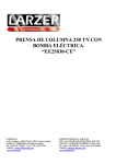
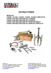
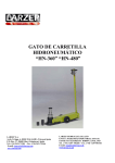
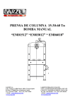
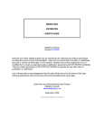
MANUAL DE INSTRUCCIONES Y MANTENIMIENTO INSTRUCTION & MAINTENANCE SHEET BOMBAS MANUALES DE SIMPLE Y DOBLE EFECTO SINGLE & DOUBLE ACTING HAND PUMPS ESPAÑOL-ENGLISH W00307, W10707, W20707, W11207, W21207, W22307, W24307 X22307, X24307 DECLARACION DE CONFORMIDAD DECLARACION DE CONFORMIDAD DECLARATION OF CONFORMITY LARZEP, S.A. Dirección: Avda. Urtiaga, 6 48269 Mallabia ESPAÑA Declaramos bajo nuestra exclusiva responsabilidad la conformidad de los productos a los que refiere esta declaración, con las disposiciones de la directiva: 2006/42/CE We, LARZEP, S.A. Address: Avda. Urtiaga, 6 48269 Mallabia SPAIN Declare under our sole responsability that the following products to which this declaration relates conform with the provisions of Directives: 2006/42/EC DECLARATION DE CONFORMITE DICHIARAZIONE DI CONFORMITÀ Nous, LARZEP, S.A. Adresse: Avda. Urtiaga, 6 48269 Mallabia SPAIN Déclarons sous notre seule responsabilité que les produits auxqueis se réfère cette déclration sont conformes aux dispositions des Directives: 2006/42/EC Noi, LARZEP, S.A. Indirizzo: Avda. Urtiaga, 6 48269 Mallabia SPAIN Dichiariamo sotto la nostra esclusiva responsabilità che i prodotti ai quali questa dichiarazione si riferisce sono conformi quanto previsto dalle Direttive: 2006/42/EC DECLARAÇÁO DE CONFORMIDADE VAATIMUSTEMUKAISUUSVAKUUTUS. Nós, LARZEP, S.A. Endereço: Avda. Urtiaga, 6 48269 Mallabia SPAIN Declaramos, sob nossa única responsabilidade, que os seguintes produtos, incluídos nesta declaração estão em conformidade com o disposto na Directiva: 2006/42/EC Me, LARZEP, S.A. Osoite: Avda. Urtiaga, 6 48269 Mallabia SPAIN Vakuutamme yksinomaan omalla vastuullamme, että seuraavat tuotteet, joihin tämä vakuutus liittyy, ovat seuraavien Direktiivien vaatimusten mukaisia: 2006/42/EC ÖVERENSSTEMMELSESERKLÆRING VERKLARINGVAN OVEREENKOMST. Vi, LARZEP, S.A. Adresse: Avda. Urtiaga, 6 48269 Mallabia SPAIN Erklærer på eget ansvar, at følgende produkter som er omfattet af denne erklæringen, er i overensstemmelse med bestemmelsene i Direktiv: 2006/42/EC Wij, LARZEP, S.A. Adres: Avda. Urtiaga, 6 48269 Mallabia SPAIN Verklaren geheel onder eigen verantwoordelijkheid dat de volgende produkten, waarop deze verklaring heeft in overeenstemming zijn met de bepalingen van Richtlijn: 2006/42/EC ERKLÆRINGOM OVERENSSTEMMELSE FÖRSÄKRAN OM ÖVERESSTÄMMELSE Vi, LARZEP, S.A. Adresse: Avda. Urtiaga, 6 48269 Mallabia SPAIN Erklærer på eget ansvar, at følgende produkter som dekkes av denne erklæringen, er i overensstemmelse med bestemmelsene i Direktiv: 2006/42/EC Vi, LARZEP, S.A. Adress: Avda. Urtiaga, 6 48269 Mallabia SPAIN Försäkrar under eget ansvar att följande produkter som omfattas av denna försäkran är i överensstämmelsemed villkoren i Direktiv: 2006/42/EC ÜBEREINSTIMMUNGSERKLÄRUNG Wir, LARZEP, S.A. Anschrift: Avda. Urtiaga, 6 48269 Mallabia SPAIN Erklären aufeigene Verantwortung, , daß folgende Produkte, auf die sich diese Erklärung bezieht, mit den Bedingungen der Direktiven, 2006/42/EC Cübereinstimmen. Tipo, Type, Typ, Tyyppi. SM / SH / SP / SMP/ SPR / SX / SMX / ST / STR / STX / SL / SAM / SAH / SAT / SATM / SSR / T / TE/ TD / D / DH / DDR / DAH / DDA / DM / DI / JM / JH / JP / Z / ZR / W / WP / X / HAM / HAE / HAZ / HAG / HAS / HFM / HFE / HAP / HAT / WI / CK / CC / CN / FU / FV / FZ / FA / CY / AA / AU / CT / C / KC / LAS / LAX A / AB / AC / B / AF / F / HN / HL / DLG / VA / VB / VC / VZ / ECE / ECM / ECZ / EE / EM / EZ / CA / CS AZ / AP / AR / AV / AS / AT / AX / AY / AM Mallabia, ESPAÑA 2009 / 12 / 29 LARZEP, S.A. Lugar y fecha, place and date, lieu et date, plats och datum, paikka ja päivämäärä, udstedelsessted og-dato, ort und datum, plaats en datum, local e data, luogo e data. Nombre y firma, name and signature, nom et signature, namn och underskrift, nimi ja nimikirjoitus, navn og underskrift, name und unterskrift, naàm en handtekening, nome e assinatura, nome e firma. 2 REQUISITOS ESENCIALES DE SEGURIDAD La correcta unión de una bomba con un cilindro a través de una manguera hidráulica, constituye una máquina concebida para levantar, tirar, doblar, retener etc...que por su gran capacidad de empuje requiere una utilización segura que anule la posibilidad de accidentes. Lea detenidamente el manual de instrucciones y ejercite con el equipo antes de la aplicación. Utilice material de protección, tales como gafas, botas y guantes de seguridad. Gafas Botas Guantes Elija un equipo que no sobrepase el 80% de su capacidad nominal durante su utilización y dentro de la amplia gama el más adecuado para la aplicación. Buscar zonas estables para los puntos de aplicación de la carga y zonas seguras para los operadores, separándolos mediante el uso de mangueras suficientemente largas. Bloquear las cargas mecánicamente una vez realizado el movimiento evitando operar debajo de estas. Utilice toda la superficie de apoyo útil del cilindro tanto en la cabeza como en la base. Prever el uso de cabezas basculantes si existe la posibilidad de aplicar cargas laterales. No exponer los equipos a fuentes intensas de calor (soldadura). Realizar las operaciones de mantenimiento con los equipos libres de carga y en lugares limpios e iluminados. Prever en la instalación elementos de control (manómetros) que nos informen de la presión de la instalación, con el fin de no superar en ningún caso la capacidad nominal del equipo. Si los criterios de seguridad así lo exigen prever la utilización de válvula y accesorios de seguridad. Los mandos de la bomba deben de actuarse manualmente, así como las conexiones entre elementos que dispongan de enchufes rápidos. Una vez utilizado el equipo, compruebe que no ha sufrido daños, límpielo y protéjalo para su almacenamiento. Limpie los enchufes rápidos antes de conectarlos y asegúrese que dicha conexión es perfecta (primeramente introducir a tope y seguidamente roscar a mano). Una mala conexión puede provocar el mal funcionamiento del equipo e incluso puede crear situaciones de peligro. Instalar el equipo de manera que las mangueras no sufran curvaturas agudas o forzadas o la acción de cargas que puedan provocar su rotura. No modificar los equipos (piezas soldadas, alargar palancas de accionamiento), sin consultar al fabricante No utilizar las mangueras para transportar los equipos. Utilizar las asas de los cilindros si las hubiera y la palanca de la bomba en posición de transporte. Al rellenar la bomba con aceite, utilizar aceite hidráulico Larzep o de semejantes características. Rellenar solamente hasta el nivel señalado y tener en cuenta que el émbolo del cilindro debe de estar recogido. Antes de efectuar cualquier tipo de aplicación asegurarse de la buena instalación, de la seguridad del puesto del operador y imposibilidad de que persona alguna pueda acceder a la zona expuesta. En cualquier caso el operador debe de estar perfectamente instruido en el manejo del equipo y actuar con los criterios lógicos de seguridad, que el movimiento de grandes cargas conlleva. GARANTÍA LARZEP, S.A. garantiza este producto sobre todos los defectos de diseño y fabricación durante dos años desde la fecha de compra. Esta garantía no incluye el uso indebido, el desgaste habitual tanto de piezas metálicas como no metálicas, el abuso, los daños por el uso del equipo por encima de su capacidad, y cualquier desgaste o uso derivado del empleo de fluidos hidráulicos, materiales y componentes no recomendados por LARZEP, S.A. Si el equipo ha sido vendido por un distribuidor no autorizado, o por partes incompletas, esta garantía queda anulada, sin ningún tipo de responsabilidad por parte de LARZEP, S.A. En el caso de reclamación, para el correcto uso de esta garantía, devuelva el equipo a LARZEP, S.A. o al distribuidor autorizado que le vendió el equipo, LARZEP, S.A. reparará o reemplazará el equipo defectuoso según se juzgue oportuno. LARZEP, S.A., no será responsable de ninguna perdida o daño que pueda ocurrir como resultado de un equipo defectuoso. 3 INSTRUCCIONES CILINDRO-BOMBA MANUAL Desembale y verifique visualmente todo el equipo, asegurándose que no haya fugas de aceite, enchufes flojos o deteriorados, roscas dañadas, etc... Nunca utilice equipos dañados o presumiblemente en mal estado. Monte la instalación según las indicaciones del dibujo comprobando que dispone de todo el material requerido. Compruebe la perfecta instalación y el buen funcionamiento del equipo sin carga, según el siguiente procedimiento. INSTALACION SIMPLE EFECTO 1. Desbloquear la palanca de accionamiento de bomba, sacando el gancho del alojamiento del portapalanca. 2. Bombear varias veces con el tornillo de accionamiento abierto (aflojar un par de vueltas del tope) para llenar el circuito interno de la bomba de aceite. 3. Cerrar el tornillo de accionamiento, girando a derechas con la mano. No es necesario apretar con fuerza. 4. Bombear con la palanca de accionamiento. Primeramente se debe de llenar la manguera de aceite. El número de emboladas dependerá de la longitud de la manguera y del caudal que suministre el pistón de la bomba. En caso de bomba de una velocidad el caudal se mantendrá en todo el movimiento, ya sea avance sin carga o en presión. En bombas de dos velocidades, en el movimiento de avance sin carga actuará el pistón grande y en el momento de contactar la carga actuará automáticamente una válvula interna de alivio del pistón grande y solamente dispondremos del aceite suministrado por el pistón pequeño, hasta los 700 kg/cm que es la presión máxima del equipo. 5. Una vez la manguera está llena de aceite, el émbolo del cilindro comenzará a avanzar. 6. Si el cilindro dispone de fin de carrera mecánico con capacidad de aguantar la presión máxima de la instalación continúe bombeando hasta alcanzar el final de carrera. 7. Si dispone de elementos de control (manómetro) notará que la presión aumenta, así mismo el esfuerzo en la palanca. 8. Continúe bombeando hasta alcanzar la presión máxima (700 kg/cm). De esta forma comprobará el buen funcionamiento de la válvula interna de seguridad y la ausencia de fugas de aceite en la instalación. 9. Mantenga la presión en la instalación durante un tiempo, sin bombear para comprobar que funcionan perfectamente la válvula de retención de la bomba. 10. Abra suavemente el tornillo de accionamiento de la bomba (giro a izquierda) con el fin de proteger la caída de la aguja del manómetro. No forzar el tornillo de accionamiento al soltar, no por más aflojar, el cilindro recoge más rápidamente. Un par de vueltas es suficiente. 11. Si el cilindro dispone de muelle de retorno (SM, SMP, SMX, SH, TE, T, SAM, SAH, SATM, CY, KC) el émbolo se recogerá automáticamente. La velocidad de recogida puede ser lenta en algunas aplicaciones. En este caso recomendamos la utilización de cilindros de doble efecto. En caso de cilindros de retorno por carga (SP, SPR, SX, SL, SSR, ST, STR, STX, SAT) para recogerlos será necesario empujar el émbolo con más o menos fuerza dependiendo del tamaño y posición del cilindro. 12. En cilindros que no disponga de fin de carrera mecánico (SSR, ST, STR, STX) no se puede realizar este tipo de prueba. En caso de no disponer de un banco de pruebas, será sobre la propia carga en la aplicación cuando comprobaremos la instalación, por lo que en este caso, esta debe de realizarse con la máxima atención, por personal con experiencia y las medidas de seguridad deben de ser ampliadas. 13. Repetir el proceso las veces que sea necesario para habituarse al manejo del equipo. 14. En caso de utilizar válvulas de cierre o antirretorno, o se trabaje con varios cilindros a través de distribuidores de caudal, tener en cuenta el efecto que tales accesorios pueden tener en el funcionamiento del equipo y marcar un proceso de actuación para no originar efectos no deseados. INSTALACION DOBLE EFECTO 1. La conexión de los enchufes rápidos tiene una importancia mayor si cabe, ya que una mala conexión no solo hace que el equipo no funcione, sino que además puede originar sobrepresiones que pueden provocar la rotura del cilindro. Tener en cuenta que manguera se conecta a la cámara de empuje y cual a la cámara de retorno. 2. Todos los cilindros Larzep de doble efecto disponen de fin de carrera mecánico que soporte la presión nominal del equipo y por tanto se podrá realizar la prueba previa descrita en los puntos anteriores. En caso de trabajar con otro tipo de cilindro, si no se tiene seguridad absoluta no se realizará esta prueba. 3. Desbloquear la palanca de accionamiento de bomba, sacando el gancho del alojamiento del portapalanca. 4. Colocar el mando de la válvula distribuidora en posición central y bombear varias veces para llenar de aceite los conductos internos. 5. Girar la palanca a un lado y bombear. El aceite fluye a través de la manguera conectada al lado del giro de la palanca de la válvula. Si dicha manguera esta conectada a la cámara de empuje del cilindro, el émbolo avanzará. El aceite de la cámara de retorno fluye libremente a través de la otra manguera al depósito de la bomba. Mientras el cilindro no alcance la carga el caudal es suministrado por el pistón grande y el pistón pequeño. 6. Continuar bombeando hasta alcanzar el fin de carrera. En este momento la válvula interna de alivio del pistón grande actuará y solo obtendremos el aceite suministrado por el pistón pequeño. Someter a presión la instalación para comprobar que no existen fugas. 7. Dejar de bombear y comprobar (preferentemente mediante un manómetro) que la instalación mantiene la presión. 8. Girar la palanca de la válvula al lado contrario y bombear. El aceite fluye a la cámara de recogida, retrocediendo el émbolo. El aceite de la cámara de empuje retorna libremente al tanque. 9. Repetir el proceso las veces que sea necesario para habituarse al manejo del equipo. 10. En caso de utilizar válvulas de cierre o antirretorno, o se trabaje con varios cilindros a través de distribuidores de caudal, tener en cuenta el efecto que tales accesorios pueden tener en el funcionamiento del equipo y marcar un proceso de actuación para no originar efectos no deseados. 4 ESSENTIAL SAFETY INSTRUCTIONS The correct union of a pump to a cylinder via a hydraulic hose constitutes a machine designed for lifting, pulling, folding and retaining operations, etc., that, due to its high thrust capacity requires safe use in order to eliminate the risk of accidents. Read the instructio ns manual carefully and practise using the equipment before application. Use protective equipment such as safety goggles, boots and gloves. Goggles Boots Gloves Choose the most suitable model for the application from the wide range available, and make sure that it will not exceed 80% of its nominal capacity during normal operation. Define stable zones for applying the load and safety zones for operators, separating them through the use of hoses of enough length. Block loads mechanically once the movement has been completed and avoids operating underneath them. Use the entire cylinder’s useful support surface, both on the head and the base. Be prepared to use tilting saddles if applying side loads. Do not expose the equipment to intense heat sources (welding). Remove loads before carrying out maintenance operations and always work in clean, well-lit areas. Include control elements (pressure gauges) in the installation in order to enable the operator to monitor the pressure in the system and ensure that the equipment’s nominal capacity is never exceeded. Be prepared to use safety valves and accessories if safety criteria demand it. The pump controls should be activated manually, as should the connections between elements equipped with couplers. Once you have finished using the device, check that it has not been damaged, clean it and protect it ready for storage. Clean the couplers before connecting and make sure the connections are perfect (first insert as far as the coupler will go and then screw in by hand). A bad connection may result in improper functioning and may even generate a safety hazard. Install the device in such a way as to ensure that the hoses are not subjected to sharp or forced bends or thrust actions that may cause them to break. Do not modify the device (welded parts, lengthening drive levers, etc.) without consulting the manufacturer. Do not use the hoses for transporting the device. Use the handles on the cylinders (when appropriate) and set the pump lever to the transportation position. When filling the pump with oil, always use Larzep hydraulic oil or another oil of similar characteristics. Fill only to the indicated level and remember that the cylinder piston should be back. Before starting operation, check that the installation is correct, the operator position is safe and the working zone is out of bounds to all personnel. In all cases, the operator should have received adequate training regarding the handling of the device and logical safety criteria associated with the movement of heavy loads. WARRANTY LARZEP, S.A. guarantees its products against all design and manufacturing defects during two years from the date of purchase. This guarantee does not include the ordinary wear of both metal and non-metal parts, abuse, using the equipment beyond its rated capacity and any wear or damage incurred as a result of using a hydraulic fluid which is not recommended by LARZEP, S.A. Please note that if the equipment is disassembled or serviced by anyone other than an authorized service dealer or by LARZEP, S.A., this guarantee is rendered null and void. In the event of a warranty claim, return the equipment, to LARZEP, S.A. or the authorized dealer which sold you the hydraulic equipment, LARZEP, S.A. will repair or replace the faulty equipment, whichever is deemed most appropriate. LARZEP, S.A. shall not be held liable for any consequential damages or losses, which may occur as a result of faulty equipment 5 CYLINDER-HAND PUMP INSTRUCTIONS Unpack and visually check all the components, making sure that there are no oil leaks, loose or damaged couplers, damaged threads, etc. Never use components that are damaged or appear to be in poor condition. Assemble the device in accordance with the instructions given in the diagram, first checking that you have all the necessary material. Check the correct installation and perfect functioning of the device with a load, in accordance with the procedure outlined below: SINGLE ACTING INSTALLATION 1. Release the pump drive lever by removing the hook from the lever-holder housing. 2. Pump manually with the drive screw open (rotate a few times to loosen) in order to fill the pump’s internal circuit with oil. 3. Close the drive screw by turning clockwise manually. You do not need to close too tightly. 4. Now pump using the drive lever. First, fill the hose with oil. The number of strokes required will depend on the length of the hose and the flow supplied by the pump piston. With single-speed pumps, the flow will remain the same at all times, regardless of the load or pressure. With twospeed pumps, the large piston will be activated during the load-free feed movement, and when the device comes into contact with the load, an internal large piston relief value will be automatically triggered and only the oil supplied by the small piston will be available up to 700 kg/cm2, which is the maximum pressure for the device. 5. Once the hose is full of oil, the cylinder piston will start to advance. 6. If the cylinder has a mechanical limit switch capable of withstanding the maximum device pressure, continue pumping until the limit switch is reached. 7. If any control elements (pressure gauges) are available, you will be able to see how the pressure increases along with the effort required to move the lever. 8. Keep pumping until you obtain the maximum pressure (700 kg/cm 2). In this way you will be able to check the correct functioning of the internal safety valve and the absence of oil leaks in the installation. 9. Maintain pressure in the installation for a short period of time (1 minute) without pumping, in order to check the correct functioning of the pump’s check valve. 10. Gently open the pump’s drive screw (by turning anticlockwise) in order to protect the fall of the pressure gauge needle. Do not force the drive screw open. The cylinder will not move back more quickly because the screw is looser. A couple of turns will be enough. 11. If the cylinder has a return spring (SM, SMP, SMX, SH, TE, T, SAM, SAH, SATM, CY, KC) the piston will move back automatically. The return speed may be slow in some applications. In this case, we recommend the use of double effect cylinders. In the case of load return cylinders (SP, SPR, SX, SL, SSR, ST, STR, STX, SAT), you will need to push the piston back using more or less force, depending on the size and position of the cylinder. 12. In cylinders without a mechanical end of stroke (SSR, ST, STR, STX) this type of test cannot be carried out. If you do not have a test bench, you will have to test the installation using the actual load in the application. This operation should be carried out with extreme care by experienced personnel and maximum safety measures should be applied. 13. Repeat the processes as many times as necessary until you are comfortable handling the device. 14. If using close or check valves, or working with various cylinders via flow distributors, remember to take into consideration the effect these accessories may have on the functioning of the device, and establish an operating procedure in order to avoid unwanted effects. DOUBLE ACTING INSTALLATION 1. The connection of the couplers is even more important here, since a bad connection will not only prevent the device from functioning, it may also generate excessive pressure build-up that may cause the break of the cylinder. Take note of which hose connects to the advance chamber and which to the return chamber. 2. All double action Larzep cylinders are equipped with a mechanical end of stroke capable of withstanding the nominal pressure. You can therefore carry out the test described in the previous section. If you are working with another type of cylinder and are not 100% sure, do not carry out this test. 3. Release the pump drive lever by removing the hook from the lever-holder housing. 4. Turn the control of the distributing valve to the central position and pump a few times to fill the internal channels with oil. 5. Turn the lever to one side and pump. Oil will flow through the hose connected to the side to which the valve lever is rotated. If this hose is connected to the cylinder’s thrust chamber, the piston will move forward. The oil in the return chamber will flow freely through the other hose to the pump tank. Flow is supplied by both the large and small pistons until the cylinder reaches the load. 6. Continue pumping until you reach the mechanical end of stroke. At this moment an internal large piston relief valve will be triggered, and only the oil supplied by the small piston will be available. Subject the installation to pressure to check for leaks. 7. Stop pumping and check (preferably using a pressure gauge) that the installation maintains the pressure level. 8. Turn the valve lever to the other side and pump. Oil will flow to the return chamber and the piston will move back. The oil in the advance chamber will flow freely back to the tank. 9. Repeat the processes as many times as necessary until you are comfortable handling the device. 10. If using close or check valves, or working with various cylinders via flow distributors, remember to take into consideration the effect these accessories may have on the functioning of the device, and establish an operating procedure in order to avoid unwanted effects. 6 MANTENIMIENTO Comprobación del nivel de aceite. - Con la bomba en posición vertical (base (1) abajo), soltar el tapón (16). En el modelo W00307 el nivel se consigue por desbordamiento del aceite por el agujero. En los otros modelos comprobar el nivel en la varilla del tapón. - Esta verificación se realizara con el cilindro recogido. Un exceso de aceite en el depósito origina presiones internas que provocan un mal funcionamiento de la bomba. - Filtrar el aceite antes de introducirlo en el depósito. Una vez utilizado el equipo, limpiarlo y engrasar las zonas expuestas a desgaste u oxidación. La articulación en la palanca de accionamiento de la bomba y las roscas del cilindro. AVERIAS Y REPARACIONES EL CILINDRO NO AVANZA AL BOMBEAR. - Falta de aceite en el depósito ____ Revisar el nivel. - Incorrecta conexión de enchufes____ Revisar las conexiones. - Cierre defectuoso de la bola de admisión (19) ____ Corregir el asiento y cambiar la bola. - Cierre defectuoso de la bola de cierre (22) ____ Corregir el asiento y cambiar la bola. EL CILINDRO NO ALCANZA O NO RETIENE LA PRESIÓN. - Válvula limitadora (12) destarada ____ Retarar la válvula. - Cierre defectuoso de la bola de retención (20) ____ Corregir el asiento y cambiar la bola. - Cierre defectuoso de la bola de cierre (22) ____ Corregir el asiento y cambiar la bola. - Retén de presión dañado (26) ____ Cambiar el retén. - Retén del cilindro dañado ____ Cambiar el retén. EL CILINDRO NO RETORNA. - Demasiado aceite en el depósito ____ Revisar el nivel. MAINTENANCE Oil level check. - With the pump in vertical position (base (1) downwards), unscrew or pry off the plug (16). On the W00307 model the level is obtained by overflow through the filling hole. On the other models check the level on the dip stick. - This check must be carried out with the cylinder fully retracted. Excessive amount of oil in the tank will lead to internal pressures which will hamper the function of the pump. - Filter the oil before filling up the pump. Once the equipment is being used the areas exposed to wear and oxidation must be cleaned and greased. BREAK DOWNS AND REPARATIONS THE CYLINDER DOESN´T AVANCE - Lack of oil in the tank ____ Check the oil. - Couplers not fully inserted ____ Check couplers. - Admission ball valve failure (19) ____ Clean the seat and replace the ball. - Closing ball valve failure (22) ____ Clean the seat and replace the ball. THE CYLINDER DOESN´T REACH WORKING PRESSURE. - Relief valve no calibrated (12) ____ Calibrate the valve. - Retention ball valve failure (20) ____ Clean the seat and replace the ball. - Closing ball valve failure (22) ____ Clean the seat and replace the ball. - Pressure seal damaged (26) ____ Replace the seal. - Cylinder pressure seal damaged (see cylinder) ____ Replace the seal. THE CYLINDER DOESN´T RETRACT - Too much oil in the tank ____ Check the level. 7 8 DESPIECE BOMBAS MANUALES SIMPLE EFECTO HAND PUMP SINGLE-ACTING PARTS LIST Referencias / Models: W00307, W10707, W20707, W11207, W21207, W22307, W24307 Nº 1 2 3 4 5 6 7 8 9 10 11 12 13 14 15 16 17 18 19 20 21 22 23 24 25 26 27 28 29 30 31 32 33 34 35 36 37 38 39 40 41 42 43 44 45 46 47 48 49 50 51 Denominación/description W00307 W10707 W20707 W11207 W21207 W22307 W24307 ** Base / base Camisa / body Pistón / piston Portapalancas / handle socket Palanca / handle Empuñadura / handle grip Tornillo accionamiento / release screw Tirante inyector / Inyector Depósito / tank Tapa depósito / end cap Eje depósito / tie rod Válvula limitadora/ relief valve (700) Válvula limitadora / relief valve (20) Eje portapalancas / hand socket pin Eje pistón/ piston pin Tapón-Tapón nivel / plug-plug label Tuerca cierre depósito / acorn nut Filtro / filter Bola de admisión / admision ball Bola de retención / ball Eje tirante inyector / pin Bola cierre / ball Tórica tornillo accionamiento / O-ring Junta base-depósito / joint Junta depósito-tapa / joint Taza pistón / Seal U-cup Tórica de apoyo / O-ring Arandela cierre camisa / washer Tórica cierre tuerca depósito / Oring Pata trasera / foot Tornillo cierre / screws Tórica tornillo cierre / O-ring Pasador tope portapalancas / elastic pin Horquilla portapalancas / transport pin Muelle horquilla / spring Arandela horquilla / washer Arandela presión / elastic washer Tope tornillo accionamiento / screw Muelle bola antiretorno 1º / spring Muelle bola antiretorno 2º / spring Muelle bola admisión / spring Tórica cierre pistón baja / O-ring Segmento tórica pistón baja / segment Guía pistón baja / guide Cierre tapón nivel/arandela / plug seal Clip eje portapalancas / clip Tapón / plug Tornillo cierre camara alta / screw Tórica tornillo cierre / O-ring Estuche cartón / box Etiqueta / label 50K0050 15D0002 54A0031 24B0005 24A0005 24C0004 50K0032 15D0023 54C0004 24B0037 24A0070 24C0006 15H0017 24F0006 51B0017 15L0095 15I0273 17C0002 50K0034 50K0034 50K0006 50K0007 54B0003 24B0037 24A0070 24C0006 50K0032 15D0023 54C0004 24B0037 24A0070 24C0006 54B0003 24B0037 24A0070 24C0006 54B0001 24B0037 24A0070 24C0006 54B0002 24B0037 24A0070 24C0006 15H0017 15H0017 15H0017 15H0017 15H0017 15H0017 51B0042 32A0013 15I0003 17C0006 51B0065 32A0014 15I0160 17C0006 15I0348 15I0347 15L0042 14B0004 13F0001 31A0001 31A0002 51B0065 32A0014 15I0160 17C0028 17C0028 15I0348 15I0347 15L0117 14B0004 13F0001 31A0001* 31A0005* 51B0022 32A0006 15I0005 17C0003 17C0004 15I0348 15I0347 15L0044 14B0004 13F0003 31A0001* 31A0005* 51B0068 15L0043 15I0006 17C0003 17C0004 15I0348 15I0347 15L0044 14B0005 13F0003 31A0001* 31A0005* 15A0008 15A0012 12C0026 14B0004 13F0001 31A0001 31A0001 15A0014 31A0001 15I0348 15I0347 15L0117 14B0004 13F0001 31A0002 31A0001 51B0042 32A0013 15I0003 17C0028 17C0028 15I0348 15I0347 15L0117 14B0004 13F0001 31A0001* 31A0005* 31A0001 31A0001 31A0001 31A0001 31A0001 31A0001 12A0047 12A0047 12A0047 12A0047 12A0047 12A0047 12A0047 ** 57F0015 57F0015 12J0001 12A0272 27A0004 57F0016 57F0016 12J0004 12A0051 57B0011 57F0016 57F0016 12J0004 57F0016 57F0017 12J0004 12A0051 57B0038 57F0016 57F0017 12J0004 57F0019 57F0019 12J0004 57F0018 57F0018 12J0004 ** ** ** ** 12A0048 12A0048 12A0048 12A0048 12A0048 12A0048 12A0049 ** 24L0037 14A0001 12A0022 24L0015 24L0015 15O0004* 12A0056* 24L0003 24L0003 15O0004* 12A0056* 24L0004 15O0004* 12A0056* 24L0005 15O0004* 12A0056* 14E0002 14E0002 14E0002 14E0002 15I0159 15I0159 15I0159 15I0159 15I0165 15I0165 13D0003 14C0004 14D0042 14A0400 13D0136 13D0003 14C0004 14D0042 15L0400 13C0008 13C0008 13D0003 14C0004 14D0042 15L0400 13D0136 13D0003 14C0004 14D0042 15L0400 13C0008 13C0008 13D0004 14C0004 14D0042 13D0004 14C0004 14D0042 13D0003 13D0004 13C0018 12A0055* 13D0047 13D0004 13C0018 12A0055* 12A0108 12A0108 57A0222 57A0222 ** ** ** ** ** 58F0210 58F0210 ** 12A0051 12A0051 12A0056 12A0056 14C0013 14C0013 ** AZ1182 14D0001* AZ1182 14D0001* AZ1182 14D0001* AZ1182 14D0001* AZ1182 21D0017 30A0017 21D0019 30A0023 21D0019 30A0023 21D0019 30A0023 21D0019 30A0023 14D0001* AZ1182 15O0002 12A0020 21D0019 30A0023 14D0001* AZ1182 15O0002 12A0020 21D0020 30A0023 ** Juego de recambios/Spare parts * Dos piezas/Two pieces 9 ** 10 DESPIECE BOMBAS MANUALES DOBLE EFECTO HAND PUMP DOUBLE-ACTING PARTS LIST Referencias / Models: X22307, X24307 Nº Denominación / description 1 3 4 5 6 9 10 11 12 13 14 15 16 17 18 19 20 24 25 26 27 29 30 31 32 34 35 36 37 39 40 41 42 43 Base/ base Pistón/ piston Portapalancas/ handle socket Palanca/ handle Empuñadura/ handle grip Depósito/ tank Tapa depósito/ end cap Eje depósito/ tie rod Válvula limitadora/ relief valve (700) Válvula limitadora/ relief valve (20) Eje portapalancas/ hand socket pin Eje pistón/ piston pin Tapón-Tapón nivel/ plug-plug label Tuerca cierre depósito/ acorn nut Filtro/ filter Bola de admisión/ admision ball Bola de retención/ ball Junta base-depósito/ joint Junta depósito-tapa/ joint Taza pistón/ Seal U-cup Tórica de apoyo/ O-ring Tórica cierre tuerca depósito/ O-ring Pata trasera/ foot Tornillo cierre/ screws Tórica tornillo cierre/ O-ring Horquilla portapalancas/ transport pin Muelle horquilla/ spring Arandela horquilla/ washer Arandela presión horquilla/ elastic washer Muelle bola antiretorno 1º/ spring Muelle bola antiretorno 2º/ spring Muelle bola admisión/ spring Tórica cierre pistón baja/ O-ring Tornillos amarre/ screw X22307 X24307 50K0061 54B0001 24B0037 24A0070 24C0006 51B0022 32A0006 15I0005 17C0006 17C0006 15I0347 15I0348 15L0044 14B0004 13F0003 31A0001(2) 31A0005(2) 57F0019 57F0019 12J0004 12A0051 12A0048 24L0004 15O0004(2) 12A0056(2) 15I0165 13D0004 14C0004 14D0042 13D0003 13D0004 13C0018 12A0055(2) 14A0201(4) 50K0063 54B0002 24B0037 24A0070 24C0006 51B0068 15L0043 15I0006 17C0006 17C0006 15I0347 15I0348 15L0044 14B0005 13F0003 31A0001(2) 31A0005(2) 57F0018 57F0018 12J0004 12A0051 12A0049 24L0005 15O0004(2) 12A0056(2) 15I0165 13D0004 14C0004 14D0042 13D0047 13D0004 13C0018 12A0055(2) 14A0201(4) * Nº Denominación / description * * * * * * * * * 44 45 46 47 48 49 50 51 52 53 54 55 56 57 58 59 60 61 62 63 64 65 66 67 68 69 70 71 72 73 74 75 76 77 * Juego de recambios/Spare parts 11 Guía pistón baja/ guide Cierre tapón nivel/arandela/ plug seal Clip eje portapalancas/ clip Tapón/ plug Tornillo cierre camara alta/ screw Tórica tornillo cierre/ O-ring Estuche cartón/ box Etiqueta/ label Conjunto válvula/ valve Cuerpo válvula/ body Distribuidor/ manifold Tapa/ cover Eje/ saft Palanca/ handle Tornillo valvula/ valve screw Arandela/ ring Tornillo tapa/ cover screw Piston/ piston Junta torica/ o-ring Segmento / antiextrusion segment Muelle/ spring Pasador elastico/ elastic pin Esfera 4/ ball Muelle/ spring Pasador elastico/ elastic pin Rodamiento/ bearing Junta torica/ o-ring Esfera 6/ ball Muelle/ spring Junta torica/ o-ring Tapón 3/8 NPT/ 3/8 NPT plug Pasador elastico/ elastic pin Base valve/ Tornillo / screw X22307 X24307 * 58F0210 14C0013 14D0001(2) AZ1182 15O0002 12A0020 21D0021 30A0023 AZ8400X 52Y0064 17B0002 15L0097 15I0306 24A0057 15O0010(2) 57B0008 (2) 14A0002 (4) 54F0001 (5) 12A0059 (6) 57A0058 (5) 13D0009 (5) 14E0010 31A0002 13D0008 14E0011 31B0002 12A0077 31A0001 (2) 13D0043 (2) 12A0420 15L0055 (2) 14E0039 50M0059(2) 14A0003 (4) 58F0210 14C0013 14D0001(2) AZ1182 15O0003 12A0020 21D0022 30A0023 AZ8400X 52Y0064 17B0002 15L0097 15I0306 24A0057 15O0010(2) 57B0008 (2) 14A0002 (4) 54F0001 (5) 12A0059 (6) 57A0058 (5) 13D0009 (5) 14E0010 31A0002 13D0008 14E0011 31B0002 12A0077 31A0001 (2) 13D0043 (2) 12A0420 15L0055 (2) 14E0039 50M0059(2) 14A0003 (4) * * * * * * * * * * * LARZEP, S.A. Avenida Urtiaga, 6 48269 MALLABIA, SPAIN Tel. +34 943 171200 Fax. +34 943 174166 e-mail: [email protected] www.larzep.com LARZEP AUSTRALIA PTY. LTD. 104 Wedgewood Road, HALLAM, VIC. 3803 AUSTRALIA Tel. +61 (3) 9796 3744 Fax. +61 (3) 9796 5964 e-mail: [email protected] www.larzep.com.au LARZEP GB LTD. 3 Commerce Way - Leighton Buzzard BEDS LU7 4RW UNITED KINGDOM Tel. +44 1525 377819 Fax. +44 1525 851990 e-mail: [email protected] www.larzep.co.uk