1
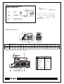
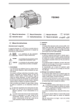
Tiper15
Manual de instrucciones
Instruction manual
Manual de instrucciones
ADVERTENCIA PARA LA SEGURIDAD
La conexión eléctrica debe ser realizada por personal técnico
cualificado.
La siguiente simbología
junto a un párrafo indica la
posibilidad de peligro como consecuencia de no respetar las
prescripciones correspondientes.
PELIGRO
riesgo de
electrocución.
El cable de alimentación debe cumplir con las exigencias de las
correspondientes normativas vigentes en cada país. Es de uso
obligado que las conexiones del cable de alimentación al motor de
la bomba, se hagan con los correspondientes terminales.
La
no
advertencia
de
esta
prescripción comporta un riesgo de
electrocución.
PELIGRO
La
no
advertencia
de
esta
prescripción comporta un riesgo de
daño a personas o cosas.
ATENCIÓN
La
no
advertencia
de
esta
prescripción comporta un riesgo de
daños al equipo o a la instalación.
Los motores monofásicos llevan protección térmica incorporada.
Siga las instrucciones de la Figura 1 para una correcta instalación
eléctrica.
La instalación debe realizarse y siguiendo la norma
"EN 60335-2-60". Asegurarse que la conexión del cable de masa
se ha realizado correctamente. Asegurarse que la conexión
equipotencial entre la bañera y la bomba se ha realizado
correctamente.
1. GENERALIDADES
Las instrucciones que facilitamos tienen por objeto informar sobre
la correcta instalación y óptimo rendimiento de nuestras bombas.
2.5. Controles previos a la puesta en marcha inicial
ATENCIÓN: Compruebe que la tensión y la frecuencia
de la red corresponden a la indicada en la placa de
características.
Son bombas centrífugas monocelulares horizontales, con motor
eléctrico incorporado.
Diseñada para trabajar con equipos compactos de hidromasajes.
Asegúrese que el eje de la bomba gira libremente.
Con dispositivo de vaciado completo para evitar el líquido residual
en cada puesta en marcha.
Deberá dotarse de un dispositivo, en el conjunto de hidromasaje,
para que la bomba no se ponga en marcha si no existe un mínimo
nivel de agua. Llene la bañera. Deberá esperar a que el agua
alcance dicho nivel (Figura 2).
Con aislamiento entre parte motor y bomba superior a 3750 V.
Concebida para trabajar con aguas limpias, exentas de sólidos en
suspensión y a una temperatura máxima de 50°C.
Asegúrese de que no exista ninguna junta o rácor con pérdidas.
LA BOMBA NO DEBE FUNCIONAR NUNCA EN SECO.
ATENCIÓN: el adecuado seguimiento de las
instrucciones de instalación y uso, así como de los
esquemas de conexión eléctricos garantiza el buen
funcionamiento de la bomba.
3. PUESTA EN MARXA
Abra todas las válvulas de paso en las tuberías, tanto en la
aspiración como en la impulsión.
PELIGRO: La omisión de las instrucciones de este
manual puede derivar en sobrecargas en el motor,
merma de las características técnicas, reducción de la
vida de la bomba y consecuencias de todo tipo, acerca
de las cuales declinamos cualquier responsabilidad.
Conecte el interruptor de suministro. El agua puede tardar unos
segundos en recorrer toda la longitud de tubería.
Compruebe el sentido de giro del motor, este debe ser horario
visto desde el ventilador.
Compruebe que la corriente absorbida sea igual o menor a la
máxima, indicada en la placa de características.
2. INSTALACIÓN
2.1. Fijación
Si el motor no funciona o no extrae agua, procure descubrir la
anomalía a través de la relación de posibles averías más
habituales y sus posibles soluciones que facilitamos en páginas
posteriores.
La bomba deberá descansar sobre una base sólida y horizontal.
Debe estar fijada a ella mediante tornillos (4 x Ø8), aprovechando
los agujeros que existen en el soporte, para asegurar la
estabilidad del montaje.
2.2. Montaje de la tubería de aspiración
4. MANTENIMIENTO
La tubería de aspiración debe poseer un diámetro igual o superior
al de la boca de entrada de la bomba, conservando
permanentemente una pendiente ascendente mínima del 2% para
evitar bolsas de aire y para posibilitar el vaciado de la bomba
(Figura 2).
Nuestras bombas están exentas de mantenimiento.
Si se prevé un tiempo de inactividad prolongada se
recomienda desmontar la bomba y guardarla en un lugar
seco y ventilado.
2.3. Montaje de las tuberías de impulsión
ATENCIÓN: en caso de avería, la manipulación de la
bomba sólo puede ser efectuada por un servicio técnico
autorizado.
Se recomienda utilizar tuberías de un diámetro igual al de la boca
de impulsión o mayor para reducir las pérdidas de carga en tramos
largos de tuberías.
Las tuberías jamás descansarán su peso sobre la bomba.
5. DESGUACE
Llegado el momento de desechar la bomba, esta no
contiene ningún material tóxico ni contaminante.
2.4. Conexión eléctrica
Este producto no debe ser tirado al contenedor normal
de basuras. Utilice el servicio local, público o privado, de
recogida selectiva de residuos.
La instalación eléctrica deberá disponer de un sistema
de separación múltiple con abertura de contactos
≥ 3 mm. La protección del sistema se basará en un
interruptor diferencial (I∆n = 30 mA).
Los componentes principales están debidamente
identificados para poder proceder a un desguace
1
selectivo.
Instruction manual
SAFETY WARNING
The electrical connection must be carried out by a qualified
technician.
next to a paragraph
The following symbology
indicates possible danger as a result of not respecting the
corresponding warnings.
DANGER
risk of
electric shock.
The power cable must comply with the corresponding regulation
requirements in force in each country. It is obligatory that the
connections from the power cable to the motor of the pump are
made with the corresponding terminals.
Not heeding this warning carries a risk
of electric shock.
DANGER
Not heeding this warning carries a risk
of harming people or things.
WARNING
Not heeding this warning carries a risk
of damaging the equipment or the
installation.
The single-phase motors incorporate thermal protection.
Follow the instructions in Figure 1 for correct electrical installation.
The installation should be carried out in accordance with regulation
"EN 60335-2-60". Check that the grounding connection has been
carried out correctly. Check that the equipotential connection
between the bath tub and the pump has been carried out correctly.
2.5. Tests prior to initial start-up
1. GENERALITIES
WARNING: Check that the tension and frequency of the
supply system correspond to that indicated on the
electrical data label.
The instructions provided give information about the correct
installation and optimal performance of our pumps.
Make sure that the shaft of the pump rotates freely.
They are centrifugal single-stage horizontal pumps, with electric
motor incorporated.
It should be fitted with a device, in the hydro-massage unit, so that
the pump does not start until there is a minimum level of water. Fill
the bath tub. Wait until the water reaches the aforementioned level
(Figure 2).
Designed for working with hydro-massage compact equipment,
with complete draining device to avoid residual liquid in each startup.
Make sure that none of the gaskets or fittings leak.
With insulation between the motor part and the pump exceeding
3750 V.
THE PUMP MUST NEVER BE DRY RUN.
Designed for working with clean water, that does not contain
suspended solids and at a maximum temperature of 50°C.
3. START-UP
Open all the flow valves on the tubes, on both the suction and
discharge.
WARNING: correctly following the instructions for
installation and use, as well as the diagrams for
electrical connections guarantees the correct functioning
of the pump.
Connect the supply switch. The water make take a few seconds to
flow along the length of the tube.
Check the rotational direction of the motor; it should be clockwise
when looked at from the ventilator.
DANGER: Disregarding the instructions in this manual
may result in overcharges in the motor, loss of technical
characteristics, reduction in the useful life of the pump
and consequences of all types, for which we do not take
any responsibility.
Check that the absorbed current is equal to or less than the
maximum, indicated on the electrical date label.
If the motor does not work or does not extract water, try to find out
what the anomaly is by checking the most common possible faults
and their possible solutions that we have provided on later pages.
4. MAINTENANCE
2. INSTALLATION
Our pumps are exempt from maintenance.
2.1. Fastening
If the pump is going to be inactive for a long time it is
advisable to dismantle it and store it in a dry, ventilated
place.
The pump should rest on a solid, horizontal base. It should be
fastened to it using screws (4 x Ø8), making use of the holes in the
support to ensure that the assembly is stable.
WARNING: in the case of breakdown, the pump may
only be handled by an authorised technical service.
2.2. Assembly of the suction pipe
The suction pipe should have a diameter the same as or exceeding
that of the mouth of the pump inlet, permanently maintaining a
minimum incline of 2% to avoid air pockets and so that can make
the draining of the pump possible (Figure 2).
5. DISPOSAL
When the time comes to dispose of the pump, it does
not contain any toxic or contaminating material.
2.3. Assembly of the discharge pipe
This product must not be disposed of in a normal rubbish
container. Use the local public or private service for
selective residue collection.
It is advisable to use pipes with a diameter equal to that of the
propulsion mouth or bigger to reduce power losses in long
stretches of pipes.
The principal components are duly identified for a
selective disposal procedure.
The pipes should never rest their weight on the pump.
2.4. Electrical connection
The electrical installation must be fitted with a multi-pole
isolator with an opening of contacts ≥ 3 mm. The
protection of the system is based on a differential switch
(I∆n = 30mA).
2
Fig. 1
ALIMENTACIÓN MONOFÁSICA
SINGLE-PHASE SUPPLY
Fig. 2
TUBERIA DE ASPIRACIÓN
SUCTION PIPE
1 - ROJO
RED
2 - BLANCO
WHITE
3 - NEGRO
BLACK
4 - CONDENSADOR
CAPACITOR
5 - LÍNEA
LINE
6 - PROTECTOR TÉRMICO
THERMAL PROTECTOR
TUBERIA DE IMPULSIÓN
DISCHARGE PIPE
NIVEL MÍNIMO DE AGUA
MINIMUM WATER LEVEL
Dimensiones / Dimensions
230V 50Hz
Tiper15 1
Q max. H max.
[l/min.]
[m]
250
8,5
A 1~
230V
1,9
12
P1
[kW]
0,4
C - mf
IP
h (%)
55
40
dBA
±1
< 70
A
[mm]
36,5
B
[mm]
158
C
[mm]
78
D
[mm]
153
E
[mm]
80
G
[mm]
309
F
[mm]
100
H
[mm]
126
J
[mm]
177
K
[mm]
100
kg
5,7
Tiper15 2
300
9,2
2,4
12
0,55
55
42
< 70
36,5
158
78
153
80
309
100
126
177
100
5,7
Tiper15 3
350
10
3
12
0,7
55
44
< 70
36,5
158
78
153
80
323
100
126
177
100
6,7
V/Hz esp.: Ver placa datos bomba / See pump nameplate.
3
1 - Cuerpo bomba
Pump body
2 - Rodete
Impeller
3 - Tapa bomba
Pump cover
4 - Cierre mecánico
Mechanical seal
5 - Rodamiento
Bearing
6 - Condensador
Capacitor
7-
Motor shaft
Eje motor
8 - Estator
Stator
9 - Racor aspiración
10- Racor impulsión
Suction union
Discharge union
C/134891
Edición: 01/09/2006
4