1
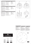
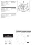
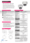
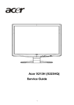
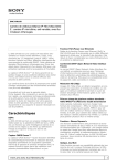
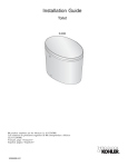
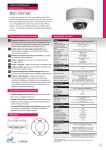
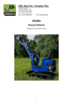
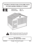
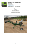
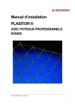
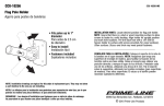
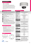
Conector de cámara.
ENGLISH
Precautions
Methods for mounting the enclosure
Packing list
• Do not attempt the disassemble the camera module
mounted within the dome. There are no user-serviceable
parts within the camera module. Refer servicing to qualified
service personnel.
There are three main ways to mount and fix the dome
enclosures:
In addition to this installation sheet:
• Vandal dome enclosure
A1: Flush mount without rear access
• 4 x no.12 x 11⁄2” fixing screws
• Handle the camera with care. Do not abuse the camera.
Avoid striking or shaking it. Improper handling or storage
could damage the camera.
A2: Flush mount with rear access
• 4 x Rubber sealing washers
• Irrespective of whether the camera is in use or not, never
face it towards the sun. Use caution when operating the
camera in the vicinity of spotlights or other bright lights and
light reflecting objects.
Note: Always use the template provided.
• 4 x Brown wall plugs
A3: Normal surface mount using the outer ring
• 2 x Ceiling clamp brackets
• 2 x M4 x 40 screws
When mounting externally
• Power and video connection lead
When mounting externally using the four base holes, use the
supplied rubber washers (shown in A3) within the mounting
holes to ensure moisture resistant seals. Also, ensure that the
cable entry through either of the knockout panels A2 is suitably sealed against moisture ingress.
• 1 x Torx key bit
Précautions
Montage du boîtier
Contenu
• Ne pas essayer de démonter le module caméra fixé à
l’intérieur du dôme. Certaines parties du module caméra
seraient détériorées. Attribuer l’entretien à un personnel
qualifié.
Il y a quatre types de montage pour la fixation des dômes :
En plus du manuel d’instructions :
• Dôme fixe anti-vandale
• Do not operate the camera beyond its temperature, humidity
or power source ratings. Use the camera under conditions
where temperatures are within –5oC to +45 oC, and relative
humidity is below 80% (non-condensing).
A2
A1
FRANÇAIS
A1 : Montage encastré sans accès arrière
• 4 x no.12 x 11⁄2” vis de fixation
A2 : Montage encastré avec accès arrière
• Manipuler la caméra avec attention. Ne pas brusquer la
caméra : éviter de la frapper ou de la secouer. Manipulation
et stockage incorrect pourraient endommager la caméra. Ne
jamais la positionner face au soleil.
• Utiliser la caméra avec précaution lorsque celle-ci fonctionne
aux alentours de projecteurs, lumières brillantes ou d’autres
objets réfléchissants.
• 4 x rondelle en caoutchouc
A3 : Montage surface normal utilisant l’anneau extérieur
• 4 x chevilles marrons
Note : Toujours utiliser le gabarit de fixation.
• 2 x vis M4x40
• 2 x supports d’attache pour plafond
Pour le montage en extérieur
Lors d’un montage à l’extérieur en utilisant les quatres trous
de la base, utiliser les joints en caoutchouc fournis (montré
sur A3) sur les trous de montage pour assurer l’étanchéité.
Aussi, s’assurer que l’entrée du câblage aussi par les plaques
de sécurité A2 est convenablement scellée contre l’entrée
d’humidité.
• 1 x clé Torx
Precauciones
Montaje de la caja
Contenido
• No intente desmontar el módulo de la caja sin el dome. No
se suministran las partes del modulo de la cámara. Para
servicios y reparaciones siempre utilice personal qualificado.
Existen cuatro maneras de montar y fijar la caja :
Además de éste manual de instrucciones
• Vandal Dome
• Maneje la cámara con cuidado. No abuse la cámara. No
agitarla o golpearla. El úso inapropiado de la cámara podría
dañarlo.
A2: Montaje encajado con acceso trasero
A3: Montaje sobre superficie utiliznado el anillo exterior
• 4 x alcayatas marrones de pared
• Independiemente de que la cámara se encuentre en uso o
no, nunca la coloque de cara al sol. Utilícela con precaución
en los focus de lúz, luces brillantes y objetos que reflejen
lúz.
Nota : Siempre utilizar l’esquema de fijación.
• 2 x M4x40 tornillos
Para el montaje de la camarà al exterior
• 2 x ganchos para fijar en el techo
• Ne pas faire fonctionner la caméra au-delà de ses limites
de température, humidité ou puissance. Utiliser la caméra
lorsque les températures sont entre -5°C et +45°C, et
l’humidité relative en dessous de 80% (sans condensation).
EN Ceiling clamp brackets x 2.
• Câble de connexion vidéo et alimentation
FR Supports d’attache pour plafond x 2.
ES Ganchos para fijar en el techo x 2.
A3
ESPAÑOL
• No utilizar la cámara más allá de su temperatura, humedad
y alimentación. Utilizar la cámara únicamente en condiciones de temperatura entre 5°C y 45°C y con relativa
humedad, bajo 80% (sin condensación)
A1: Montaje encajado sin acceso trasero
• 4 x no.12 x 3’’ tornillos di fijación
• 4 x arandella de goma
Quando un montaje al exterior utilizando los cuatros agujeros
de la base, utilizar los arandelas de goma suministradas
(mostrada su A3) en los agujeros de montaje por cerrar herméticamente. Asegúrese que l’entrada de los cables ,también
a través de los paneles A2, està cerrado de manera adecuada
contro l’humedad.
EN Rubber washers to create moisture seal when fixing externally.
FR Rondelles en caoutchouc pour sceller contre l’humidité lors d’un montage à l’extérieur.
ES Arandelas de goma por cerrar contro l’humedad cuando montaje al exterior.
• Cable de conexión para alimentación y video.
• 1 x llave Torx
EN
Template
FR
Schéma
ES
Esquema
ENGLISH
FRANÇAIS
ESPAÑOL
Surface mount
Montage saillie
Montaje superficie
Create four holes of diameter 7mm at template positions ‘T1’.
Use 4 x brown wall plugs and 4 x (no.12 x 11⁄2”) screws. When
mounting externally, use a rubber washer at each mounting
hole in the base to ensure moisture resistant seals.
Flush mount
Create an aperture in the mounting surface to a diameter of
110mm as indicated by ‘T5’.
With rear access: Create two holes at template positions
‘T2’ of diameter 5mm. Use 2 x (M4 x 40) fixing screws and 2 x
ceiling clamp brackets.
Without rear access: Create two holes at template positions
‘T2’ of diameter 7mm and insert a brown wall plug into each.
Use 2 x (no.12 x 11⁄2”) screws.
Cable access (in all cases)
Créer quatres trous de 7mm de diamètre en utilisant la
position T1 du schéma. Utiliser 4 chevilles et 4 vis de (no.12
x 11⁄2”). Lors d’un montage à l’extérieur, utiliser une rondelle
imperméable (joint d’étanchéité) sur chaque trou de la base
pour assurer une clotûre hermétique.
Montage encastré
Créer une ouverture de 110mm dans la surface de montage
comme indiqué par la position T5.
Avec accès par l’arrière : Créer deux trous de 5mm de
diamètre indiqué par la position T2. Utiliser les 2 vis de fixation
(M4 x 40) et les 2 support d’attache pour plafond.
Sans accès par l’arrière : Créer deux trous de 7mm de
diamètre indiqué par la position T2. et introduire une cheville
dans chaque. Utiliser deux vis de (no.12 x 11⁄2”).
Accès du câblage (dans tous les cas)
Use either the base knockout ‘T3’ or the internal side
knock-out shown in fig E overleaf. Hole ‘T4’ may be used in
conjunction with the outer ring when surface mounting to
avoid opening the external knock-out.
Utiliser le panneau de sécurité de la base T3 ou bien le
panneau de sécurité intérieur (voir fig.E). Le trou T4 peut
être utilisé en conjonction avec l’anneau du dôme lors d’un
montage en surface pour éviter d’ouvrir le panneau de sécurité
extérieur.
Hacer cuatros agujeros de 7mm de diámetro utilizando la posición T1 del esquema. Utilizar 4 alcayatas y 4 tornillos de no.12
x 11⁄2”. Quando un montaje al exterior, utilizar arandelas de
goma en los agujeros de montaje por cerrar herméticamente
Montaje encajado
Crear un abertura en la superficie de montaje con un diámetro
de110mm como aparece indicado por la posición T5.
Con acceso trasero: Hacer dos agujeros de 5mm de
diámetro indicado por la posición T2. Utilizar los 2 tornillos de
fijación M4 x 40 y los 2 ganchos para fijar en el techo.
Sin acceso trasero: Hacer dos agujeros de 7 mm de
diámetro indicado por la posición T2. Introducir alcayatas y
utilizar dos tornillos de no.12 x 11⁄2”.
Acceso de los cables (en cualquier caso)
Utilizar el panelo de seguridad de la base T3 o el panelo de
seguridad interior (mirar fig.E). El agujero T4 puede estar
utilizado conjuntamento con l’anillo del dome cuando montaje
in superficie por evitar de abrir el panelo de seguridad exterior.
#
FR
ES
Vandal resistant dome installation sheet
Manuel d’instructions dôme fixe anti-vandale
Manual de instrucciones vandal dome
Document: SML PN0172 - 1.2
EN
T4
FR
T3
ES
T1
T2
T5
T1
VP23W
Template
Schéma
Esquema
T2
T1
VP20W
EN
T1
VP20W
VP23W
ENGLISH
E
Installing the dome enclosure
1 Remove the dome cover
E2
Use the supplied Torx driver to loosen (but not remove) the
four cover screws. The screws will be held in place by the
gasket.
EN E1: Base knock-out; E2: Internal side knock-out.
FR E1: Panneau de sécurité de base; E2: Panneau de securité intérieur.
E1
2 Use the template to mark-out and prepare the
mounting area
ES E1: Panelo de seguridad de la base; E2: Panelo de seguridad interior.
3 Open the required knock-out panel
Carefully drill (or tap out) either the base knock-out (E1) or
internal side knock-out (E2) to the size required to allow
cable entry.
4 Attach the dome enclosure to mounting holes
E3
EN E3: Cable access without opening the external side
knock-out; E4: Cable access via the external side
knock-out.
Using the supplied screws appropriate to the mounting surface, fix the dome enclosure (and outer ring, if necessary)
to the prepared mounting area.
IMPORTANT: If the dome is being mounted externally and
using the four base holes, use the supplied rubber washers
within each of the four mounting holes of the dome base
to ensure moisture resistant seals.
5 Connect the wiring
Insert the wiring through the knock-out hole, into the enclosure and connect to the small, or large, circuit board as
fitted (fig F). The large circuit board offers two alternative
ways to connect power and video cables:
• Terminal strip - used for permanent bare wire connections, or
• Supplied lead - used for permanent or temporary test
connections.
Note: Ensure that the cables remain clear of the camera
rotation area.
Cable types
• Video cable - use a good quality coaxial cable with
75ohm impedance.
• Power cable - use suitably insulated two-core cable
capable of carrying 3W at 12VDC or 24VAC.
IMPORTANT: If the dome is being mounted externally, use
a suitable sealant around the cable access hole to ensure a
moisture resistant seal.
FR E3: Accès câbles sans ouvrir le panneau intérieur;
6 Fit the camera assembly
Connect the camera to the small, or large, circuit board
as fitted (fig G) and then place the camera chassis/gimbal
bracket onto the three mounting pillars within the enclosure. Insert and tighten the three gimbal securing screws
(fig H).
Note: Gimbal screws are supplied with both the housing
and the camera assembly (when supplied separately),
therefore, you should have three screws left over.
7 Adjust the camera position and test
Slightly loosen the three inner camera chassis locking
screws (fig J) so that the camera chassis becomes free to
move. Rotate and pan the camera chassis to the required
position and then tighten the camera chassis locking
screws to fix it in position.
Note: For specific camera adjustments (i.e. focussing and
settings), please see the Dome camera supplement sheet.
8 Replace the dome cover
Ensure that the o-ring seal is in position, replace the dome
cover and use the supplied Torx key to tighten the four
cover screws - DO NOT OVERTIGHTEN.
E4: Accès câbles par le panneau intérieur.
ES E3: Acceso cables sin abrir el panelo interior; E4: Ac-
ceso cables a través el panelo interior.
FRANÇAIS
Montage du boîtier
E4
1 Enlever le couvercle supérieur
Utiliser la clé « Torx » fournie pour déserrer (ne pas
enlever) les quatres vis du couvercle. Les vis seront tenues
en place par le joint.
2 Utiliser le gabarit (schéma) pour préparer la zone
de montage.
3 Enlever les plaques de sécurité
Enlever (ou percer) avec précaution la plaque de sécurité
de la base (E1) ou intérieure (E2) à la taille nécessaire pour
permettre l’entrée du conduit (câblage).
F
4 Fixer le boîtier aux trous de montage
EN F1: Power 12VDC or 24VAC; F2: Power 12VDC only; F3:
Power Ground; F4: Video output.
FR F1: Alimentation 12VDC ou 24VAC; F2: Alimentation
12VDC seulement; F3: Alimentation (terre); F4: Sortie
vidéo.
GN
D
VID
ES F1: Alimentación 12VDC o 24VAC; F2: Alimentación
solamente 12VDC; F3: Alimentación tierra; F4: Conector de
video out.
0V
12
V
F2
F1
F4
1 Quitar la cobertura del dome
Utilizar la llave Torx incluida para aflojar (pero non quitar)
los cuatros tornillos de la cobertura. Los tornillos quedarán
sujetos por el anillo de goma.
2 Utilizar el esquema incluido para marcar y preparar el area de montaje
EN G1: Camera connector.
FR G1: Connecteur caméra.
3 Quitar los paneles
G1
ES G1: Conector de la cámara.
GN
D
VID
0V
or
ou
o
12
V
H
H2
H2
EN Place the gimbal bracket and camera chassis (H1) onto the
three mounting pillars. Insert and tighten the three gimbal
securing screws (H2).
FR Placer le support et chassis caméra (H1) sur les trois piliers de
montage. Visser et serrer le support avec les trois de fixation
(H2).
ES Colocar el soporte y cámara (H1) sobre los tres pilares. Apretar
el soporte con los tres tornillos de fixación (H2).
H1
J1
J2
EN Loosen the three camera chassis locking screws (J1). Rotate and pan the
camera chassis (J2) to the required position. Carefully tighten the three
screws.
FR Déserrer les vis de fixation du chassis caméra (J1). Effectuer les rotations
horizontales et verticales (J2) nécessaires vers la position demandée. Pour
bloquer, revisser les trois vis avec précaution.
J1
J1
Connecter la caméra au petit ou grand circuit PCB principal
installé (fig.G) et placer le support châssis de la caméra
sur les trois piliers de montage à l’intérieur du boîtier.
Introduire et serrer les trois vis de fixation (fig.H).
Note : les vis de fixation sont fournies avec le boîtier et
l’assemblage caméra (lorsque fournis séparemment). C’est
pourquoi, vous devriez avoir trois vis de rechange.
7 Ajuster la position de la caméra
Desserer légèrement les trois vis intérieures du support
caméra. (fig.J) pour libérer le chassis. Effectuer les rotations horizontales et verticales nécessaires vers la position
demandée. Resserer les trois vis antérieures pour fixer la
caméra.
Note : Pour les ajustements caméras (ex : mise au point,
changement des caractéristiques,…) se référer à la documentation caméra.
8 Replacer le couvercle
S’assurer que l’anneau-joint d’étanchéité est placé dans
sa position, replacer le couvercle et ressere les quatres vis
de couvercle en utilisant la clé « torx » - NE PAS SERRER
TROP FORT.
Montaje de la caja
G
J
6 Fixer l’assemblage de la caméra
ESPAÑOL
F3
G1
Introduire les fils de branchement à l’intérieur du dôme par
la plaque de sécurité enlevée. Brancher au petit ou grand
circuit PCB principal installé (fig.F). Le grand circuit PCB
principal offre deux méthodes alternatives de branchement
de l’alimentation et de la vidéo :
• Bornier à vis : branchement permanent
• Connecteur : branchement permanent ou temporaire
(test)
Note : S’assurer que les câbles reste à l’écart et ne gêne
pas la rotation de la caméra.
Types de câbles
• Câble vidéo – Utiliser un câble coaxial de bonne qualité
avec 75 ohm d’impédance.
• Câble d’alimentation – Utiliser deux câbles convenablement isolés capables de transporter 3W à 12VDC ou
24VAC.
IMPORTANT : Si le dôme est monté en extérieur, utiliser un
enduit d’étanchéité approprié autour du trou d’accès du
câblage afin de sceller hermétiquement le boîtier.
F3
or
ou
o
F4
Utiliser les vis fournies adéquates pour la surface de
montage, fixer le boîtier (et anneau extérieur si nécessaire)
sur la zone de montage préparée.
IMPORTANT : Si le dôme est monté en extérieur et en
utilisant les quantres trous de la base, utiliser les joints
d’étanchéité fournis sur les quatres trous afin de sceller
hermétiquement le boîtier.
5 Branchement
ES Aflojar los tornillos de fixación del soporte cámara (J1). Rotare horizonl-
tamente y verticalmente la cámara (J2) en la posición adecuada. Por
bloquear, apretar los tres tornillos de fixación.
Con mucho cuidado, quitar o empujar hacia fuera los
paneles de la base (E1) o interna laterales (E2) a la medida
apropriada por l’entrada del conducto (cable)
4 Fijar la caja a la superficie di montaje
Utilizando los tornillos apropriados, fijar la caja a el área
preparada de montaje (y anillo exterior si necesario).
IMPORTANTE : Si el dome esta montado al exterior y utilizando los cuatros agujeros de la base, utilizar los arnadelas
de goma suministrades en los cuatros agujeros por cerrar
herméticamente la caja.
5 Conectar
Introducir los cables al interior de la caja a través del
tapone de seguridad quitado. Conectar al pequeño o
grande circuito principale instalado (fig F). El grande
circuito PCB prinicipale propone dos métodos alternativas
de conexión del alimentación y video:
• Terminal alineado: conexión permanenente
• Toma : conexión permanente o provisional (prueba)
Note : Asegurarse que los cables se encuentran fuera del
área de rotación de la càmara.
Tipos de cables
• Cable de video – Utilizar un cable coaxial de buena
calidad con 75ohm.
• Cable di alimentación – Utiliser dos cables aislado
adecuado y capaz de llevar 3W a 12VDC o 24VAC.
IMPORTANTE : Si el dome esta montado al exterior, utilizar
un producto impermeable por todas partes del agujero di
accesso de los cables por cerrar herméticamente la caja.
6 Volver a colocar el montaje de la cámara
Conectar la cámara a al pequeño o grande circuito
principale PCB instalado (fig.G) y a continuaciòn colocar el
soporte sobre los tres pilares que se encuentran dentro la
caja. Volver a colocar y apretar los tres tornillos de fixaciòn
(fig.H).
Note : Los tornillos di fixaciòn estanno suministrados con
la caja y la cámara (cuando suministrado por separado). E
porque deberias tomarte tres tornillos de sobra.
7 Ajustar la cámara en posición.
Aflojar un poquito los tres tornillos interiores que permitan
el soporte moverse con libertad (fig.G). Colocarlo en la
posición adecuada y apretar de nuevo los tres tornillos para
fijar estar posición.
Note : Referir a la “Page supplémentaire caméra dôme”
por los adaptaciónes. (ex : Nivelar il campo di visión, ….).
8 Volver a colocar la cobertura del dome
Asegurarse que el anillo de aislamento interior se encuentra en la posición adecuada. Colocar la cobertura y utilizar
la llave Torx dada para apretar los cuatros tornillos – SIN
PASARSE APRETANDO.