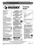
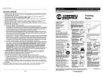
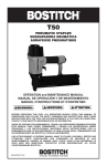
1
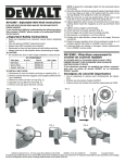
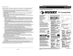
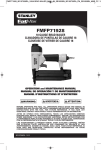
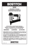
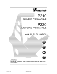
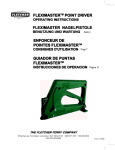
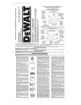
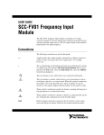
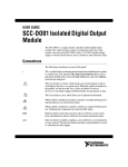
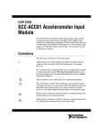
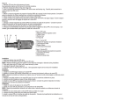
COLLAR
LOWER
CYLINDER
O-RING
SPRING
D518005 - O-Ring Replacement
Instructions
6. With the free hand, remove the lower cylinder O-ring and gently release the collar and spring.
• Remove the spring by turning it slightly as it is pulled off.
• Remove the retainer band (#603561) from the spring retainer
(#395204).
FOR USE WITH DEWALT FRAMING NAILERS MODELS
D51823 TYPE 2, D51845 TYPE 2, D51822 AND D51844
NOTE: The model number and type number of your nailer is
stamped into the tool housing near the air fitting.
If you should have difficulty understanding the following
instructions, contact a DEWALT service center or an authorized
DEWALT service person, or call 1-800-4-DEWALT.
603413
395204
603561
Important Safety Instructions
• Read and understand tool instruction manual before attempting
repairs.
• Use only genuine DEWALT Replacement Parts.
• Always wear ANSI compliant eye protection.
• Disconnect air from tool and remove all nails before servicing.
• Always point tool in safe direction when reconnecting air supply.
CAUTIONS:
• Do not allow dirt, dust or other foreign materials to enter the tool.
• Be careful not to scratch or damage the O-rings or any internal
surfaces.
390146
7. Remove the spring retainer (white plastic ring, #395204) by
spreading it enough to clear the body of the engine and pulling
it off.
TABLE 1
O-ring desc.
# in kit
part #
Identifier
Outer Exhaust
1
608615
White Dot
Inner Cylinder
1
606640
Small White O-ring
Inner Exhaust
1
608617
Orange Dot
Outer Cylinder
1
612096
White Ring
Outer Bulkhead
2
390156
Green Dot
Lower Cylinder
1
390146
Blue Dot
Other Included Parts
Cylinder Seal
1
390140
Check Seal
1
390159
Frame Seal
1
608610
Grease Tube
2
606112
Piston O-ring
1
608611
Retainer band
1
603561
8. Remove the bulkhead (#395215)
9. At this point, all the O-rings identified in the exploded view are
exposed on the tool.
10. Remove all O-rings and the cylinder seal (#390140) as identified in the parts drawing and in the O-ring identifier Table 1.
Replace all O-rings, coating each one with a layer of supplied
grease to insure proper seating when reinstalled. No grease is
needed on the check seal.
11. Reassemble the engine in reverse order.
CAUTION: The smaller white O-ring (#606640) must only be
used in the location indicated on the parts drawing. The use of any
other O-ring in this position could result in excessive wear over the
life of the tool and potential inadvertent firing.
12. Before installing engine into the housing, make sure that the
bumper is properly seated in the bottom of the frame.
13. Insert the engine assembly into frame and push it down as far
as possible.
14. Replace the piston O-ring (#608611) on the driver blade/piston
assembly. Insert the driver blade/piston assembly into cylinder.
1. Disconnect air from tool before servicing or repairing.
2. Remove all nails from the magazine and nosepiece before
servicing or repairing.
3. Remove the 4 top cap screws using a 5mm Allen wrench.
Remove the top cap.
4. Pull out the engine assembly and piston/driver blade assembly.
If necessary, pry the cylinder out of housing using the handle of
a hammer or other tool.
15. Liberally apply supplied grease to the inner and outer exhaust
O-rings before assembling the top cap and gasket (#608610) to
the engine frame.
16. With a gentle turning motion, assemble the top cap onto the
engine and frame. The cap should slide easily. If not, remove
the cap and reassemble.
17. Push downward to fully seat cap of frame.
5. Place the engine assembly upside down on work surface so
that the spring is toward the top. Use one hand to compress the
collar (#395203) and spring (#603413) so that the lower cylinder O-ring (#390146 with 1 Blue Dot) is exposed.
1
18.
19.
20.
21.
22.
Replace and tighten top cap screws snugly to prevent leaks.
Ensure that the trigger and contact trip are working smoothly.
Set the pressure on compressor or air line at 80 psi.
Ensure that there are no nails in the magazine or nosepiece.
Pointing the tool in safe direction, connect tool to air supply.
check for leaks. The tool must not leak air.
23. Check for proper operation of tool. If tool continues to leak air or
if problems persist, take the nailer to a DEWALT service center.
24. If warning labels are missing or damaged, request free replacements from a DEWALT service center.
5. Inverser l’ensemble moteur sur la surface de travail de façon à
ce que le ressort soit sur le dessus. D’une main pousser sur le
collier (no. 395203) et le ressort (no. 603413) pour exposer le
joint torique du cylindre inférieur (no. 390146 avec 1 point bleu).
COLLIER
D518005 – Directives pour changer les
joints toriques
À UTILISER AVEC LES CLOUEURS POUR CHARPENTE
DEWALT, MODÈLES D51823 TYPE 2, D51845 TYPE 2, D51822
ET D51844
REMARQUE : Le numéro de modèle et de type de votre cloueur
est inscrit sur le boîtier de l’outil près de l’entrée d’air.
Si les directives suivantes ne semblent pas claires, communiquer avec un centre de service DEWALT ou un technicien
DEWALT qualifié, ou composer le 1 800 433-9258 (DEWALT).
6. De l’autre main, retirer le joint torique du cylindre inférieur puis
relâcher lentement collier et ressort.
• Retirer le ressort en le tournant légèrement tout en le tirant.
• Retirer la bande de retenue (no. 603561) de la coupelle
d’appui du ressort (no. 395204).
Consignes de sécurité importantes
• Lire et comprendre le manuel avant d’entreprendre des réparations.
• N’utiliser que des pièces d’origine DEWALT.
• Toujours porter des lunettes de protection approuvées par
ANSI.
• Débrancher l’outil du circuit d’alimentation en air et retirer tous
les clous avant d’effectuer l’entretien.
• Toujours pointer l’outil dans une direction sûre lorsqu’on
raccorde le circuit d’alimentation en air.
MISE EN GARDES :
• Ne pas laisser la saleté, la poussière ou toute autre matière
étrangère pénétrer à l’intérieur de l’outil.
• Prendre soin de ne pas rayer ou endommager les joints
toriques ou toute autre surface interne.
TABLEAU 1
Joint torique
Qté
Pièce
desc.
dans kit
no.
Déflecteur
1
608615
d’échappement externe
Cylindre interne
1
606640
Déflecteur
1
608617
d’échappement interne
Cylindre externe
1
612096
Boîtier externe
2
390156
Cylindre inférieur
1
390146
Autres pièces inclues
Joint de cylindre
1
390140
Joint en caoutchouc
1
390159
Joint de châssis
1
608610
Tube de graisse
2
606112
Joint torique du piston
1
608611
Bande de retenue
1
603561
JOINT
TORIQUE DU
CYLINDRE
INFÉRIEUR
RESSORT
603413
395204
603561
390146
7. Retirer la coupelle d’appui du ressort (anneau en plastique
blanc, no. 395204) en l’écartant assez pour la faire sortir du
corps du moteur.
Identifiant
Point blanc
8. Retirer le boîtier (no. 395215).
9. À ce stade, tous les joints toriques illustrés sur la planche sont
visibles sur l’outil.
10. Retirer tous les joints toriques et le joint de cylindre (no.
390140) illustrés sur la planche et inclus dans le tableau 1 identifiant les joints toriques. Changer tous les joints toriques, en
recouvrant chacun d’eux d’une couche de la graisse pourvue à
cet effet pour assurer leur adhérence. Inutile de graisser le joint
en caoutchouc.
11. Réassembler le moteur en suivant les indications en sens
inverse.
MISE EN GARDE : Le petit joint torique blanc (no. 606640) doit
être installé uniquement dans l’emplacement indiqué sur la
planche. L’utilisation de tout autre joint torique à cet endroit pourrait
réduire la durée de vie de l’outil et provoquer des démarrages
intempestifs.
12. Avant de réinstaller le moteur dans son boîtier, s’assurer que la
butée est correctement installée au fond du châssis.
13. Insérer l’ensemble moteur dans le châssis et l’enfoncer bien à
fond.
14. Remettre le joint torique du piston (no. 608611) sur l’ensemble
lame/piston de l’enfonceur. Insérer l’ensemble lame/piston de
l’enfonceur dans le cylindre.
Petit joint
torique blanc
Point orange
Anneau blanc
Point vert
Point bleu
1. Débrancher l’outil du circuit d’alimentation en air avant
d’effectuer les opérations d’entretien ou de réparation.
2. Retirer tous les clous du chargeur et de l’embout avant
d’effectuer les opérations d’entretien ou de réparation.
3. Retirer les 4 vis du capuchon à l’aide d’une clé Allen de 5mm.
Retirer le capuchon.
4. Enlever l’ensemble moteur et piston/lame de l’enfonceur. Si
nécessaire, extraire le cylindre hors du boîtier avec le manche
d’un marteau ou de tout autre outil.
15. Graisser généreusement avec la graisse pourvue à cet effet les
joints toriques du déflecteur d’échappement interne et externe
2
avant de remettre le capuchon et la garniture (no. 608610) sur
le châssis.
16. En tournant doucement, réassembler le capuchon sur le
moteur et le châssis. Le capuchon devrait rentrer facilement.
Dans le cas contraire, retirer le capuchon et réassembler.
17. Appuyer sur le capuchon pour l’installer à fond sur le châssis.
1. Desconecte la toma de aire de la herramienta antes de
repararla.
2. Retire todos los clavos del cargador y la tobera antes de
repararla.
3. Retire los 4 tornillos del extremo superior con una llave Allen de
5mm. Retire el extremo superior.
18. Remettre et serrer fermement les vis du capuchon afin de
prévenir les fuites.
19. S’assurer que la gâchette et le déclencheur par contact fonctionnent bien.
20. Régler la pression du compresseur ou du circuit d’alimentation
en air à 5,6 kgs/cm2 (80 lb/po2).
21. S’assurer qu’il n’y a aucun clou dans le chargeur ou l’embout.
22. Pointer l’outil dans une direction sécuritaire, puis le raccorder
au circuit d’alimentation en air. Vérifier qu’il n’y a aucune fuite.
L’outil ne doit présenter aucune fuite d’air.
23. S’assurer que l’outil fonctionne correctement. En présence
d’une fuite d’air ou d’un problème quelconque, apporter l’outil à
un centre de service DEWALT.
24. En cas de perte ou d’endommagement des étiquettes d’avertissement, communiquer avec un centre de service DEWALT
afin d’en obtenir de nouvelles sans frais.
4. Tire de la unidad del motor y la unidad del pistón/impulsador
para sacarlas. Si fuera necesario, use el mango de un martillo
u otra herramienta para hacer palanca y sacar el cilindro de la
caja protectora.
5. Coloque la unidad del motor boca abajo sobre la superficie de
trabajo para que el resorte quede mirando hacia arriba. Use
una mano para comprimir el collar (#395203) y resorte
(#603413) para que el anillo tórico del cilindro inferior (#390146
con 1 lunar azul) quede expuesto.
COLLAR
ANILLO
TÓRICO
INFERIOR DEL
CILINDRO
RESORTE
D518005 - Instrucciones para cambiar
anillos tóricos
A SER UTILIZADAS CON LAS CLAVADORAS DEWALT
MODELOS D51823 TIPO 2, D51845 TIPO 2, D51822 Y D51844
NOTA: El número de modelo y de tipo de su clavadora viene
estampado en la caja protectora de la herramienta, cerca de la
toma de aire.
Si le es difícil entender las siguientes instrucciones, contacte
al centro de servicio DEWALT o a personal de servicio autorizado por DEWALT, o llame al 1-800-433-9258 (DEWALT).
6. Con la mano libre, retire el anillo tórico del cilindro inferior y
suelte suavemente el collar y el resorte.
• Gire ligeramente el resorte y tire de él para retirarlo.
• Retire la banda de retención (#603561) del retenedor del
resorte (#395204).
Instrucciones importantes de seguridad
603413
• Lea y comprenda bien el manual de instrucciones de la herramienta antes de intentar realizar alguna reparación.
• Utilice sólo repuestos DEWALT originales.
• Siempre use protección ocular aprobada por ANSI.
• Desconecte la toma de aire de la herramienta y retire todos los
clavos antes de reparar la unidad.
• Siempre apunte la herramienta en una dirección segura cuando
vuelva a conectar la toma de aire.
PRECAUCIONES:
• No permita que le entre tierra, polvo u otro material ajeno a la
herramienta.
• Tenga cuidado de no rasguñar o dañar los anillos tóricos o las
superficies internas.
Desc. del
anillo tórico
Escape exterior
Cilindro interior
Escape interior
Cilindro exterior
Mamparo exterior
Cilindro inferior
TABLA 1
# en
no. de
el kit
pieza
1
608615
1
606640
1
608617
1
612096
2
390156
1
390146
Otras piezas incluidas
Sello del cilindro
1
390140
Sello de revisión
1
390159
Sello del marco
1
608610
Tubo de grasa
2
606112
Anillo tórico del pistón 1
608611
Banda de retención
1
603561
395204
603561
390146
7. Retire el retenedor del resorte (anillo de plástico blanco,
#395204) extendiéndolo lo suficiente como para que pase el
cuerpo del motor y tirando de él.
Idenitificador
Lunar blanco
Anillo tórico
blanco pequeño
Lunar naranjo
Anillo blanco
Lunar verde
Lunar azul
8. Retire el mamparo (#395215).
9. Todos los anillos tóricos identificados en la ampliación del
diagrama deberían estar expuestos en la herramienta.
10. Retire todos los anillos tóricos y el sello del cilindro (#390140),
como aparece identificado en el diagrama de piezas y en el
identificador de anillos tóricos de la Tabla 1. Cambie todos los
anillos tóricos, recubriendo cada uno con una capa de grasa
incluida para asegurar que queden debidamente instalados.
No se necesita aplicar grasa al sello de revisión.
11. Vuelva a ensamblar el motor siguiendo los pasos anteriores en
orden inverso.
3
PRECAUCIÓN: El anillo tórico más pequeño y blanco (#606640)
sólo debe utilizarse en la ubicación indicada en el diagrama de
piezas. El uso de cualquier otro anillo tórico en esta posición podría
resultar en un desgaste excesivo a lo largo de la vida útil de la herramienta y en el disparo accidental de clavos.
12. Antes de instalar el motor en la caja protectora, asegúrese que
el top esté debidamente instalado en la parte inferior del
marco.
13. Inserte la unidad del motor en el marco y empújela lo más
abajo que pueda.
14. Cambie el anillo tórico del pistón (#608611) en la unidad de la
hoja del impulsador/pistón. Inserte la unidad de hoja del impulsador/pistón en el cilindro.
15. Aplique bastante grasa (incluida) a los anillos tóricos interiores
y exteriores del escape antes de ensamblar el extremo superior y la junta (#608610) al marco del motor.
16. Con un movimiento giratorio suave, ensamble el extremo superior sobre el motor y el marco. El extremo debería deslizarse
fácilmente. Sino, retire el extremo y vuelva a ensamblarlo.
17. Empuje hacia abajo para instalar completamente el extremo
del marco.
18. Vuelva a poner y ajuste bien los tornillos del extremo superior
para evitar fugas.
19. Asegúrese que el gatillo y el activador por contacto estén funcionando bien.
20. Ponga la presión del compresor o la línea de aire en 5,6
kgs/cm2 (80 psi).
21. Asegúrese que no queden clavos en el cargador o la tobera.
22. Apunte la herramienta en una dirección segura y conéctela a la
toma de aire. Revise si hay fugas. La herramienta no debe
tener fugas.
23. Revise que la herramienta esté funcionando debidamente. Si
la herramienta sigue teniendo fugas de aire o si el problema
continúa, lleve la clavadora a un centro de servicio DEWALT.
24. Si las etiquetas de advertencia están dañadas o se han perdido, solicite que se las cambien en el centro de servicio
DEWALT.
Parts Drawing / Planche / Diagrama de piezas
OUTER EXHAUST O-RING (WHITE DOT)
PART # 608615
JOINT TORIQUE DU DÉFLECTEUR
D’ÉCHAPPEMENT EXTERNE (POINT BLANC)
PIÈCE NO. 608615
ANILLO TÓRICO EXTERIOR DEL ESCAPE
(LUNAR BLANCO) PIEZA # 608615
INNER EXHAUST O-RING (ORANGE DOT) PART # 608617
JOINT TORIQUE DU DÉFLECTEUR D’ÉCHAPPEMENT
INTERNE (POINT ORANGE) PIÈCE NO. 608617
ANILLO TÓRICO INTERIOR DEL ESCAPE (LUNAR NARANJO)
PIEZA # 608617
CYLINDER SEAL
PART # 390140
JOINT DE CYLINDRE,
PIÈCE NO. 390140
SELLO DE CILINDRO
PIEZA # 390140
BULKHEAD PART # 395215
BOÎTIER, PIÈCE NO. 395215
MAMPARO PIEZA # 395215
OUTER CYLINDER O-RING
(WHITE RING) PART # 612096
JOINT TORIQUE DU CYLINDRE
EXTERNE (ANNEAU BLANC),
PIÈCE NO. 612096
ANILLO TÓRICO EXTERIOR DEL
CILINDRO (ANILLO BLANCO)
PIEZA # 612096
OUTER BULKHEAD O-RINGS
(GREEN DOT) PART # 390156
JOINTS TORIQUES DU BOÎTIER
EXTERNE (POINT VERT),
PIÈCE NO. 390156
ANILLOS TÓRICOS EXTERIORES
DEL MAMPARO (LUNAR VERDE)
PIEZA # 390156
CHECK SEAL PART # 390159
JOINT EN CAOUTCHOUC,
PIÈCE NO. 390159
SELLO DE REVISIÓN
PIEZA # 390159
INNER CYLINDER O-RING
(SMALL WHITE O-RING) PART # 606640
JOINT TORIQUE DU CYLINDRE INTERNE
(PETIT JOINT TORIQUE BLANC),
PIÈCE NO. 606640
ANILLO TÓRICO INTERIOR DEL CILINDRO
(ANILLO TÓRICO BLANCO PEQUEÑO)
PIEZA # 606640
RETAINER BAND
PART # 603561
BANDE DE RETENUE,
PIÈCE NO. 603561
BANDA DE RETENCIÓN
PIEZA # 603561
SPRING PART # 603413
RESSORT, PIÈCE NO. 603413
RESORTE PIEZA # 603413
SPRING RETAINER PART # 395204
COUPELLE D’APPUI DU RESSORT,
PIÈCE NO. 395204
RETENEDOR DEL RESORTE
PIEZA #395204
LOWER CYLINDER O-RING (BLUE DOT) PART # 390146
JOINT TORIQUE DU CYLINDRE INFÉRIEUR (POINT BLEU), PIÈCE NO. 390146
ANILLO TÓRICO INFERIOR DEL CILINDRO (LUNAR AZUL) PIEZA # 390146
COLLAR PART # 395203
COLLIER, PIÈCE NO. 395203
COLLAR PIEZA # 395203
DEWALT Industrial Tool Co., 701 East Joppa Road, Baltimore, MD 21286
(MAR04-CD-1)
Form No. 612100-00
D518005
Copyright © 2002, 2004
The following are trademarks for one or more DEWALT power tools: the yellow and black color scheme; the “D” shaped air intake grill; the array of
pyramids on the handgrip; the kit box configuration; and the array of lozenge-shaped humps on the surface of the tool.