1
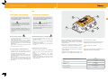
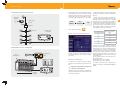
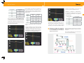
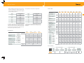
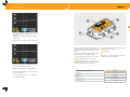
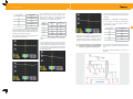
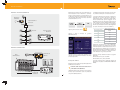
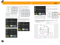
ore
um o r
iR at
ed er
0
tor G e n
a
93
r
ne e
.5
Ge o i s R e f
N
B
0d
Hz
M
ON
96
47
23
0
7
1 2
5
6
0
3
4
0
-1
dB
-3
9
8
-2
.
dx
lA
ve
Le
50
.1
5
Ref. 5930
Art.Nr. RG2150
ES
EN
IT
DE
Generador de Ruido
Noise generator
Generatore di Rumore
Rauschgenerator
Manual de Instrucciones
User´s Manual
Manuale del’Utente
Bedienungsanleitung
w w w. t e l e v e s . c o m
3
ES
EN
NOTAS SOBRE SEGURIDAD
SAFETY PRECAUTIONS
Antes de manipular el equipo, leer el manual de utilización y muy especialmente el apartado PRESCRIPCIONES DE SEGURIDAD.
Before using the equipment, read the manual and
pay particular attention to the SAFETY MEASURES
section.
sobre el equipo significa: “CONEl símbolo
SULTAR EL MANUAL DE UTILIZACIÓN”.
on the equipment means:
The symbol
“CONSULT THE USER MANUAL”. This may also appear
in the manual as a warning or caution symbol.
Recuadros de ADVERTENCIAS Y PRECAUCIONES
pueden aparecer a lo largo de este manuapara evitar riesgos de accidentes a personas o daños al equipo u otras propiedades.
WARNING and CAUTION messages may appear in
this manual in order to avoid the risk of accidents
or to avoid causing damage to the equipment or to
other property.
Prescripciones de Seguridad
Safety measures
• El uso del equipo de forma no especificada no asegura la
protección del mismo.
• Utilizar el equipo solamente en sistemas o instalaciones
con el negativo de medida conectado a potencial de
tierra.
• Este equipo puede ser utilizado en instalaciones con
Categoría de Sobretensión I y ambientescon Grado de
Polución 2.
• Tener siempre en cuenta los márgenes especificados
tanto para la alimentación como para a medida.
• The non-specified use of the equipment does not ensure
its safety.
• This equipment should only be using in systems
or installation connected to a supply line with the
corresponding ground terminal.
• This equipment can be used in installations with
Overvoltage Category II and in environments with
Pollution Degree 2.
• Always take the specified margins into account both for
the powering as well as for the measurements.
Conservación y Mantenimiento
Maintenance
• El mantenimiento a efectuar por el usuario se limita a la
limpieza del mismo, el resto de operaciones deben ser
efectuadas por personal especializado en el mantenimiento de instrumentos.
• No emplear para la limpieza productos a basede hidrocarburos aromáticos o disolventes, estos productos pueden dañar los materiales plásticos de la carcasa.
• Limpiar la caja solamente con un trapo humedecido con
agua y en caso de ser necesario con un poco de jabón
aplicando de forma suave. Dejar secar completamente
el aparato antes de volver a utilizarlo.
• The user should only clean the equipment, the other
maintenance work must be carried out by specialised
personnel.
• Do not use any cleaning products with aromatic hydrocarbons or solvents, these products can harm the plastic
elements of the housing.
• To clean the box, use a damp (with water) cloth only and
if necessary, carefully use some soap. Let the equipment
dry completely before using it again.
Adaptador TDT de alta sensibilidad
5
4
IT
DE
NOTE PER LA SICUREZZA
SICHERHEITSHINWEISE
Prima di utilizzare il dispositivo leggere completamente il manuale di istruzioni e in particolare il capitolo NORME DI SICUREZZA.
Lesen Sie die Sicherheitshinweise sorgfältig durch,
bevor Sie das Gerät in Betrieb nehmen, vor allem die
UNFALLVERHÜTUNGSVORSCHRIFTEN.
sopra il dispositivo significa:
Il simbolo
“CONSULTARE IL MANUALE DI ISTRUZIONI”. In questo manuale può apparire anche come simbolo di
precauzione o avvertenza.
auf dem Gerät bedeutet:
Das Symbol
“BEDIENUNGSANLEITUNG NACHLESEN”.
4
3
ore
um t o r
di R r a
re n e
30
rato G e
59
ne s e
.
e
f
G oi
Re
N
x.
Ad
1
el
Riquadri di AVERTENZA E PRECAUZIONE possono
essere presenti in questo manuale per evitare rischi di incidenti a persone o danni al prodotto o altri
oggetti.
0d
2
0
7
5
6
0
ON
ES
96
47
23
3
4
0
-1
dB
5
1
2
Unfallverhütungsvorschriften
• L’uso del prodotto in maniera non conforme non assicura la protezione dello stesso.
• Utilizar il prodotto solamente in sistemi o installazioni
con il negativo di misura connesso a potenziale di terra.
• Questo prodotto può essere utilizzato in installazioni con
Categoria di Sovratensione I e in ambienti con Grado di
Inquinamento 2.
• Tenere sempre in conto i margini specificati tanto per la
alimentazione come per le misure.
• Der nicht bestimmungsmässigen Einsatz des Gerätes
gefährtet Ihren Schutz.
• Verwenden Sie das Gerät nur wenn die Anlage geerdet
ist.
• Das Gerät darf nur verwendet werden, wenn die Anlage
der VDEVorgaben entspricht.
• Die angegebenen Grenzparameter sind zwingend zu
beachten.
• Il mantenimento da parte dell’utilizzatore si limita alla
pulizia del prodotto, il resto delle operazioni devono essere effettuate da personale specializzato.
• Non utilizzare per la pulizia del prodotto sostanze a base
di idrocarburi aromatici o solventi. Questi prodotti possono essere dannosi.
• Pulire solo con uno straccio inumidito con acqua e dove
sia necessario con poco sapone in maniera dolce. Asciugare completamente il dispositivo prima di riutilizzarlo
nuovamente.
9
8
-2
-3
HINWEISE UND WARNUNGEN können überall in
der Bedienungsanleitung auftreten um (Lebens-)
Gefahren zu vermeiden.
Norme di Sicurezza
Conservazione e Mantenimento
B
v
Le
50
.1
5
Hz
M
Reiningung und wartung
• Überlassen Sie Wartungsarbeiten stets qualifiziertem
Fachpersonal. Führen Sie nur die Reinigung des Gerätes
durch.
• Vermeiden
Sie
Lösungsmittel
und
sonstige
Reinigungsmittel die die Kunstoffeteile des Gehäuses
beschädigen können.
• Benutzen Sie zur Reinigung ein trockenes Tuch und
reinigen Sie lediglich die Oberfl äche. Öffnen Sie auf
keinen Fall das Gerät.
Dispositivo diseñado para realizar pruebas de atenuación y planicidad en instalaciones de SMATV y
CATV, usándolo conjuntamente con un medidor
de campo Televés.
Dispone de un conmutador rotativo que permite
variar el nivel de salida en 10 ± 2 dB en 10 pasos.
Salida de señal normal. Entrada de corriente
procedente de la instalación para la alimentación del simulador.
1
lida principal debe ser cargada.
3
4
5
Conmutador rotativo que permite variar 10 ± 2
dB el nivel de salida en ambos conectores.
Led indicador de encendido.
Conector para alimentar exteriormente el simulador mediante el adaptador DC.
Salida atenuada 30dB respecto a la que se obtiene en 1. Si se utiliza la salida atenuada, la sa-
2
Características técnicas
Alimentación (externa o a través del cable coaxial)
Consumo
Conector de salida
Frecuencia
5930
12 ...... 18 V
<=2W
“F” hembra
5 - 2150 MHz
Nivel de salida máximo
80 ± 3dBμV/3MHz
Regulación nivel salida
0 - 10 dB
Generador de Ruido
7
6
El generador de ruido se puede alimentar mediante un adaptador de red, o bien desde el medidor
mediante el cable de RF. Para acceder al menú de
alimentación de previos en el medidor de campo,
se pueden seguir los siguientes pasos en el menú:
Comprobación de una instalación
Generador
de ruido
Generador ruido
Noise Generator
Señal antena o
TV cable
Ref. 5930
-30 dB
Level Adx.
5 - 2.150 MHz
2
3
ON
8
7
9 0 1
6 5 4
0 - 10 dB
234796
CONFIG.
MEDIDAS
LNB y
PREAMPLIF.
LNB
Mezclador
Toma TV
Entrada señal
de medidor
Comprobación de la central T03
Ref. 5930
Level Adx.
5 - 2.150 MHz
2
3
ON
8
7
9 0 1
6 5 4
0 - 10 dB
Cuando se trabaja con el generador de ruido, se
recomienda seleccionar en el medidor la medida
de potencia.
Generador de
ruido
Generador ruido
Noise Generator
-30 dB
234796
C55
C58
C61
C65-69
Ejemplos de utilización:
A continuación se explican brevemente algunos
ejemplos de las aplicaciones del generador de ruido:
Toma TV
.- Comprobación del estado de un tramo de
cable antes de su instalación:
PWR
1
C49 C52 C42 C61 C55 C58 C65-69
5086
Entrada
señal de
medidor
- Conecte el generador de ruido al medidor. Observe que el espectro del ruido generado es prácticamente plano. Cuanto mayor sea la longitud
del cable que vaya a comprobar, mayor debe ser
la potencia que entregue el generador de ruido. A
continuación se muestra una pequeña tabla con
las potencias mínimas recomendadas en función
de la longitud de cable a comprobar (se ha tomado
como ejemplo el cable T100 -ref. 2141-).
O bien, pulsar la tecla rápida
Entonces se abrirá la ventana de Alimentación:
5498
Alimentación
- Configure el medidor de campo en modo analizador, seleccione Full Span y seleccione la medida de
potencia.
Utilizando el generador de ruido y el medidor de
campo podrá comprobar el estado de un tramo de
cable antes de instalarlo.
Metros de cable (T100)
Mínima potencia de salida
del generador de ruido
(dBμV)
10
43
25
47
50
55
75
62
100
70
150
80
Seleccione en el medidor el nivel de referencia
adecuado. Tome nota de la medida de potencia en
varias frecuencias a lo largo de la banda terrestre, y
a continuación hacer lo mismo en banda satélite.
Asímismo debe tener en cuenta en ancho de banda y el filtro de resolución utilizados en la medida,
ya que las medidas de potencia a la entrada y a la
salida deben realizarse con los mismos valores de
estos parámetros.
En este ejemplo tomamos como referencia las siguientes frecuencias:
Banda terrestre: 200, 500 e 800 MHz
Banda satélite: 1000, 1750, 2150 MHz
Las medidas de potencia para las frecuencias de
referencia son (hechas con BW=8 MHz y RBW=250
KHzW):
ES
Generador de Ruido
9
8
Frecuencia (MHz)
Potencia (dBμV)
200
80.0
500
78.5
800
78.9
1000
78.8
1750
2150
79.5
Frecuencia
(MHz)
Atenuación
(dB/m)
82.5
200
0.08
6.8
500
0.12
10.2
En las especificaciones del cable utilizado aparecerán la atenuación por metro (dB/m) que sufre
la señal. Dicha atenuación varía con la frecuencia,
aumentando a medida que aumenta la frecuencia.
En la siguiente imagen se puede observar la señal a
la entrada (en banda terrestre):
frecuencia correspondiente, es decir, para cada
frecuencia la potencia medida debería ser:
En este ejemplo se ha tomado como referencia el
cable de interior/exterior T-100 (ref.2141), y una
longitud de cable de 85 m. La atenuación total se
calcula multiplicando la atenuación/m por la longitud del cable.
800
1000
0.15
0.18
12.75
15.3
0.24
20.4
2050
0.27
22.95
- Conecte el generador de ruido a un extremo del
cable.
- Conecte el medidor en el otro extremo del cable,
configúrelo en modo espectro y seleccione “Full
Span”. Podrá comprobar que el espectro de la señal recibida ya no es plano, sino que el nivel va
disminuyendo a medida que aumenta la frecuencia, tal como se ve en la siguiente imagen:
Banda Terrestre
En el ejemplo las medidas de potencia de la señal
a la salida del cable deberían ser las siguientes,
aproximadamente:
Atenuación
total (dB)
1750
Banda Terrestre
POTENCIAsalida = POTENCIAentrada - ATENUACIÓNTOT
Banda Satélite
- Compruebe que la potencia medida en el medidor en todas las frecuencias de referencia se
corresponde con los teóricos según la longitud
del cable y de los factores de atenuación de la
.- Evaluación de pérdidas de la instalación
de cualquier frecuencia comprendida entre 15 y 2150 MHz (ver las características
del generador de ruido):
2
Frecuencia (MHz)
Potencia (dBμV)
200
73.2
500
68.3
800
66.15
1000
63.5
1750
59.1
2150
59.55
Resulta muy útil para comprobar que la red de distribución llega sin pérdidas a todas las tomas de la
instalación.
Como ejemplo utilizaremos una sencilla instalación en una vivienda unifamiliar:
ES
Generador de Ruido
11
10
- Primero debemos seleccionar una serie de frecuencias de referencia y medir la potencia que
entrega el generador en cada una de ellas (igual
que en el ejemplo anterior).
En este ejemplo seleccionamos las siguientes:
Cable T100
Referencias
2141
214107
214105
2155
215503
2126
212601
215101
Banda
Frecuencia (MHz)
Banda
Frecuencia (MHz)
Cubierta exterior
mat´l
PVC
PVC
PVC
PE
PE
PVC
PVC
PVC
LSFH
Retorno
20.00
BIV
471.25
mm
6,6
6,6
6,6
6,6
6,6
6,6
6,6
6,6
BI
55.25
BIV-BV
607.25
Diámetro exterior
ømax.
FM
99.00
BV
855.25
blanco
blanco
negro
negro
negro
blanco
blanco
blanco
si
si
si
si
si
si
si
si
mat´l
Cu
Cu
Cu
Cu
Cu
Cu
Cu
Cu
%
20
20
20
20
20
27
27
14
Al
+Pt
+Al
Cu
+Pt
BS-b
120.00
FI-1
950.00
BIII-1
175.25
FI-2
1350.00
BIII-2
274.25
FI-3
1750.00
DAB
210.00
FI-4
2150.00
Color de la cubierta
Lámina
antimigratoria
Malla
Res. conductor exterior
A continuación se muestran las tablas con las especificaciones de cada uno de los elementos de la
instalación:
Repartidores
Características técnicas
543501
Margen frec.
MHz
5- 47 MHz
Atenuación
47-862 MHz
4,5
5- 47 MHz
5,5
dB
47-862 MHz
950 - 2400 MHz
543702
543802
6,5
8
7
7,5
9
9,5
6,5
-
10
-
6,5
-
9,5
-
11
-
9
5 - 862 MHz
>15
7
>17
>15
950 - 2400 MHz
>15
>15
>15
>15
Corriente máx.
V
40
mA
300
Cu
+Pt
Cu
+Pt
Cu
+Pt
>75
>75
>75
>75
>75
>75
>75
>75
Cu
Cu
Cu
Cu
Cu
Cu
Cu
Cu
Res. conductor
central
ohm/
Km
20
20
20
20
20
20
20
18
Diámetro cond. central
ømax
mm
1,13
1,13
1,13
1,13
1,13
1,13
1,13
1,12
Capacidad
pF/m
55
55
55
55
55
56,5
56,5
55
m
100
250
100
100
250
100
250
100
200 MHz
0,08
0,08
0,08
0,08
0,08
0,08
0,08
0,07
500 MHz
0,12
0,12
0,12
0,12
0,12
0,13
0,13
0,12
800 MHz
0,15
0,15
0,15
0,15
0,15
0,16
0,16
0,15
1000 MHz
0,18
0,18
0,18
0,18
0,18
0,19
0,19
0,17
0,20
Rechazo entre salidas
Tensión máx.
Cu
+Pt
%
8,5
-
Cu
+Pt
mat´l
9,5
9,5 .. 12
mat´l
Al
+Pt
+Al
Dieléctrico
Blindaje (EN50117)
Metros/embalaje
5-2400
3,5
950 - 2400 MHz
Atenuación
543602
Composición de la
lámina entre
dieléctrico y malla
Atenuaciones
Lo primero que haremos será calcular las atenuaciones para todas las tomas. Para ello habrá que
tener en cuenta los metros de cable que hay desde
la cabecera hasta cada una de las tomas y los elementos pasivos (separadores y tomas).
ES
0,21
0,21
0,21
0,21
0,21
0,22
0,22
1750 MHz
0,24
0,24
0,24
0,24
0,24
0,25
0,25
0,23
2050 MHz
0,27
0,27
0,27
0,27
0,27
0,28
0,28
0,25
2150 MHz
0,27
0,27
0,27
0,27
0,27
0,29
0,29
0,26
2300 MHz
0,28
0,28
0,28
0,28
0,28
0,30
0,30
0,27
1350 MHz
dB/m
Tomas finales
Pérd. inserción typ (dB)
Referencia
5226
Tipo
TV-SAT
MATV
SAT-FI
5-862 MHz
950-2150 MHz
---
---
Pérd. derivación typ (dB)
Salida
MATV
SAT-FI
5-862 MHz
950-2150 MHz
R/TV
0,6
---
SAT
---
1,5
Paso DC
24v@350 mA
SAT
IN
Generador de Ruido
13
12
Calcularemos paso a paso, a modo de ejemplo las
atenuaciones de la toma de la Habitación 2 de la
2ª planta:
La atenuación total será:
Atenuación repartidor_5435 + Atenuación
Atenuacióncable + Atenuacióntoma
Metros de cable T100
5+1+7 = 13 metros de cable
Frecuencia
+
La atenuación de cada elemento dependerá de la
frecuencia, así tendremos:
Atenuación
20
repartidor_5438
Frecuencia
3.5 + 9.5 + 13x0 + 0.6 = 13.6 dB
Hay que tener en cuenta que, tanto el ancho de
banda como el filtro de resolución, deben ser
iguales al hacer las medidas de potencia de la señal entregada por el generador y las medidas de
potencia de la señal en las tomas (o en cualquier
elemento de la red en el que se desee realizar la
medida)
.- Comprobación de la cabecera de una instalación:
- Conecte el medidor de campo a la salida de la
misma
- De esta forma podemos comprobar el correcto
funcionamiento de todos los elementos que la
conforman, así como la ecualización de los niveles de los canales que forman la cabecera.
3
Atenuación
471.25
5 + 8.5 + 13x0.12 + 0.6 = 15.16 dB
55.25
4.5 + 8.5 + 13x0 + 0.6 = 13.6 dB
607.25
4.5 + 8.5 + 13x0.12 + 0.6 = 15.16 dB
99
4.5 + 8.5 + 13x0 + 0.6 = 13.6 dB
855.25
4.5 + 8.5 + 13x0.15 + 0.6 = 15.55 dB
120
5.5 + 9.5 + 13x0.18 + 1.5 = 18.84 dB
4.5 + 8.5 + 13x0 + 0.6 = 13.6 dB
950
175.25
4.5 + 8.5 + 13x0.08 + 0.6 = 14.64 dB
1350
5.5 + 10 + 13x0.21 + 1.5 = 19.73 dB
210
4.5 + 8.5 + 13x0.08 + 0.6 = 14.64 dB
1750
5.5 + 10.5 + 13x0.24 + 1.5 = 20.62 dB
274.25
4.5 + 8.5 + 13x0.08 + 0.6 = 14.64 dB
2150
5.5 + 11.5 + 13x0.27 + 1.5 = 22.01 dB
- Conecte el generador de ruido a la entrada de la
cabecera. Tenga en cuenta que el nivel de entrada no debe ser muy alto para que no sature los
elementos de la cabecera. Recuerde que si utiliza
la salida de -30dB debe colocar la carga de 75 W
en la salida principal.
Generador ruido
Noise Generator
Ref. 5930
2º Planta
Frec.
20
55.25
99
120
Hab1
12.1
12.1
12.6
12.6
175.25 274.25
12.6
13.4
Resultando la siguiente tabla:
-30 dB
210
471.25
13.4
13.8
607.25 855.25
13.8
14.1
950
1350
1750
2150
18.3
18.6
18.9
19.2
12.1
12.1
12.6
12.6
12.6
13.4
13.4
13.8
13.8
14.1
18.3
18.6
18.9
19.2
Hab2
12.1
12.1
12.6
12.6
12.6
13.56
13.56
14.04
14.04
14.4
18.66
19.11
19.47
19.83
Hab3
12.1
12.1
12.6
12.6
12.6
13.64
13.64
14.16
14.16
14.55
18.93
19.32
19.71
20.10
Salon1
13.6
13.6
13.6
13.6
13.6
14.24
14.24
14.56
14.56
14.8
17.94
18.68
19.42
20.66
Salon2
13.6
13.6
13.6
13.6
13.6
14.24
14.24
14.56
14.56
14.8
17.94
18.68
19.42
20.66
Hab1
13.6
13.6
13.6
13.6
13.6
14.32
14.32
14.68
14.68
14.95
18.12
18.89
19.66
20.93
Hab2
13.6
13.6
13.6
13.6
13.6
14.64
14.64
15.16
15.16
15.55
18.84
19.73
20.62
22.01
Cocina
13.6
13.6
13.6
13.6
13.6
14.32
14.32
14.68
14.68
14.95
18.12
18.89
19.66
20.93
- La potencia de señal a la salida del generador de
ruido ha de ser de al menos 60 dBμV para que
compense los 22 dB de atenuación sufridos en
las frecuencias altas en la peor toma de la instalación
- Al igual que en el ejemplo anterior, tome nota de
la medida en todas las frecuencias de referencia.
5 - 2.150 MHz
2
3
ON
9 0 1
6 5 4
0 - 10 dB
Est.
Como se puede observar, la peor toma es la de la
habitación 2 de la 2ª planta, ya que es la que presenta mayor atenuación en todas las frecuencias.
Level Adx.
8
7
- A continuación conecte el generador de ruido a
la entrada de la red de distribución, tal como se
indica en la imagen de la instalación.
- Realice la medida de las frecuencias de referencia seleccionadas en la toma más desfavorable o
en el punto o puntos donde queramos evaluar
las pérdidas. La potencia medida debe coincidir,
aproximadamente, con la teórica, que se calculará de la siguiente manera:
PotenciaSALIDA = PotenciaENTRADA - Atenuación
234796
C55
C58
C61
C65-69
PWR
1º Planta
De manera análoga se calculan la atenuación teórica en el resto de las tomas de la instalación.
4
.- Análisis de la respuesta en frecuencia de
amplificadores y filtros, permitiendo así
su ajuste.
si utiliza la salida de -30dB debe colocar la carga de
75 W en la salida principal.
En este caso suele ser recomendable utilizar la salida de -30 dB del generador de ruido para evitar
saturar el amplificador monocanal. Recuerde que
- Conectar el generador de ruido a la entrada del
amplificador (en este caso se trata de un amplificador monocanal). La señal a la salida del generador es la siguiente:
ES
Generador de Ruido
15
14
4
3
ore
um t o r
di R r a
re n e
30
rato G e
59
ne s e
.
e
f
G oi
Re
N
x.
Ad
1
el
9
8
2
0
7
5
6
0
-2
ON
96
47
23
EN
3
4
0
-1
dB
-3
0d
B
v
Le
50
.1
5
Hz
M
5
- Conectar el medidor de campo a la salida del amplificador
- Comprobar que el ruido a la entrada no satura el
amplificador.
1
2
- A continuación se muestra la señal a la salida del
filtro:
A device designed to carry out attenuation and
flatness testing in F.I. satellite installations with no
entry signal, connected to a Televés field strength
meter.
Equipped with a thumbwheel allowing the output
level to be varied by 10 ± 2 dB in 10 steps.
Normal signal output. Electrical connection
from installation to power the simulator.
1
2
3
4
5
Thumbwheel to vary the output level in both
connectors by 10 ± 2 dB.
LED indicator
Connector to provide external power to the
simulator using the DC adaptor.
Output attenuated by 30 dB compared to
output obtained in 1. If the attenuated output
is used, the main output must be charged.
La ganacia de potencia de un amplificador monocanal se calcula de la siguiente manera:
GANANCIA=POTENCIAsalida - POTENCIAentrada
La ganancia del amplificador del ejemplo sería:
100.4 - 44.1 = 56.3 dB.
- Realizar los ajustes necesarios en el filtro hasta
que la salida sea óptima.
Technical data
Power supply (external or via coaxial cable)
Consumption
Output connector
Frequency
5930
12 ...... 18 V
<=2W
“F” hembra
5 - 2150 MHz
Maximum output level
80 ± 3dBμV/3MHz
Output level regulator
0 - 10 dB
Noise generator
17
16
The noise generator can be powered by an mains
adaptor, or by the meter via an RF cable. In order to
do this simply select the pre-amplifier powering in
the meter’s corresponding menu.
To access the pre-amplifier powering menu in the
field strength meter, you can follow these steps:
In the terrestrial band:
Checking an installation
Noise
generator
Generador ruido
Noise Generator
TV antenna or
cable signal
Ref. 5930
-30 dB
Level Adx.
5 - 2.150 MHz
2
3
ON
8
7
9 0 1
6 5 4
0 - 10 dB
234796
CONFIG.
MEASURE
Mixer
TV socket
Measuring device
signal input
LNB &
PREAMPLIF.
LNB
Verification of T03 headend
Noise
generator
Generador ruido
Noise Generator
Ref. 5930
-30 dB
Level Adx.
5 - 2.150 MHz
2
3
ON
8
7
9 0 1
6 5 4
0 - 10 dB
C55
Toma TV
It is advisable to select the power measurement
in the field meter when working with the noise
generator.
234796
C58
C61
C65-69
Application examples:
A few applications of the noise generator are
briefly explained below:
.- Checking the condition of a section of the
cable before installing:
PWR
1
C49 C52 C42 C61 C55 C58 C65-69
5086
Measuring
device
signal input
- Connect the noise generator to the field meter.
Check that the generated noise spectrum is
nearly flat. The longer the cable you are going to
check, the bigger the powering produced by the
noise generator should be. A small table with the
recommended minimum powering, depending
on the length of the cable to be checked, is shown
below (the wire T100 -ref.2141 has been used as an
example).
Length of cable in
metres (T100)
Minimum output powering
of the noise generator
(dBμV)
10
43
25
47
50
55
Or, press the fast button
This will open the Powering window:
5498
Power supply
- Configure the field meter to analyze mode, select
Full Span and select the powering measurement.
By using the noise generator and the field meter
it is possible to check the condition of a section of
the cable before installing it.
75
62
100
70
150
80
Select the adequate reference level on the meter.
Note down the measurement of the powering in
several frequencies along the terrestrial band, and
then do the same with the satellite band. Likewise
you must take into account the bandwidth and the
resolution filter used in the measurement, as the
powering measurements at the input and at the
output should be measured with the minimum
values for these parameters.
In the next example we use the following
frequencies as a reference:
The terrestrial band: 200, 500 e 800 MHz
The satellite band: 1000, 1750, 2150 MHz
The powering measurements for the reference
frequencies are (with BW=8 MHz and RBW=250
KHzW):
EN
Noise generator
19
18
of the corresponding frequency, in other words,
that for each powering measurement frequency
should be:
In this example the T-100 (ref. 2141) interior/
exterior cable, and 85 m for the length of the
wire have been taken as a reference. The total
attenuation is calculated by multiplying the
attenuation/m by the length of the cable.
Frequency (MHz)
Powering (dBμV)
200
80.0
500
78.5
800
78.9
1000
78.8
1750
79.5
Frequency
(MHz)
Attenuation
(dB/m)
2150
82.5
200
0.08
6.8
500
0.12
10.2
Frequency (MHz)
Powering (dBμV)
800
0.15
12.75
200
73.2
1000
0.18
15.3
500
68.3
1750
0.24
20.4
800
66.15
2050
0.27
22.95
1000
63.5
In the used cable specifications, the attenuation
per meter (dB/m), that the signal undergoes will
appear. This attenuation varies with the frequency,
growing as the frequency increases.
In the following image you can see the signal at the
input (in the terrestrial band):
In the example the powering measurements
of the signal at the cable output should be
approximately as follows:
Total
attenuation (dB)
- Connect the noise generator to one end of the
cable.
- Connect the field meter to the other end of the
cable, configure it in spectrum mode and select
“Full Span”. You will see that the spectrum of the
received signal is no longer flat, but that the level
decreases as the frequency increases, as shown in
the following picture:
The terrestrial band
The terrestrial band
The satellite band
POWERINGoutput = POWERINGinput - ATTENUATIONTOT
The satellite band
- Check that the powering measurement in the
field meter in all reference frequencies matches
the theoretical frequencies depending on the
length of the cable and the attenuation factors
.- Assessment of the losses in the installation
of any frequency between 15 and 2150 MHz
(see the noise generator specifications):
2
1750
59.1
2150
59.55
It is very useful to see that the distribution network
reaches all the installation sockets without any
losses.
We will take a simple installation in a house as an
example:
EN
Noise generator
21
20
- Firstly we have to select a series of reference
frequencies and measure the power provided by
the generator in each one of them (the same as in
the previous example).
In this example we have selected the following:
T100 cable
References
Outer sheat
mat´l
Max. outer diameter
mm
Band
Frequency (MHz)
Band
Frequency (MHz)
Return signal
20.00
BIV
471.25
Color sheat
BI
55.25
BIV-BV
607.25
Anti-migrating film
FM
99.00
BV
855.25
Braid
BS-b
120.00
FI-1
950.00
BIII-1
175.25
FI-2
1350.00
Outer conductor
resistance
BIII-2
274.25
FI-3
1750.00
DAB
210.00
FI-4
2150.00
The first thing we do is calculate the attenuation
for all the sockets. In order to do this we have to
take into account the metres of cable from the
headend up to each of the sockets and the passive
elements (separators and sockets).
Composition of
overlapped
between dielectric
and fall
The tables with the specifications of each of the
installation elements are shown below:
Splitters
543501
5- 47 MHz
Attenuation
47-862 MHz
5- 47 MHz
4,5
Rejection between
outputs
dB
47-862 MHz
543702
215503
2126
212601
215101
PVC
PVC
PVC
PE
PE
PVC
PVC
PVC
LSFH
6,6
6,6
6,6
6,6
6,6
6,6
6,6
6,6
blanco
blanco
negro
negro
negro
blanco
blanco
blanco
si
si
si
si
si
si
si
si
mat´l
Cu
Cu
Cu
Cu
Cu
Cu
Cu
Cu
%
20
20
20
20
20
27
27
14
mat´l
Cu
+Pt
Cu
+Pt
Cu
+Pt
Cu
+Pt
Cu
+Pt
Al
+Pt
+Al
Al
+Pt
+Al
Cu
+Pt
%
>75
>75
>75
>75
>75
>75
>75
>75
Cu
Cu
Cu
Cu
Cu
Cu
Cu
Cu
Inner conductor
resistance
ohm/
Km
20
20
20
20
20
20
20
18
Max Inner conductor
diameter
mm
1,13
1,13
1,13
1,13
1,13
1,13
1,13
1,12
Capacitance
pF/m
55
55
55
55
55
56,5
56,5
55
m
100
250
100
100
250
100
250
100
200 MHz
0,08
0,08
0,08
0,08
0,08
0,08
0,08
0,07
500 MHz
0,12
0,12
0,12
0,12
0,12
0,13
0,13
0,12
800 MHz
0,15
0,15
0,15
0,15
0,15
0,16
0,16
0,15
1000 MHz
0,18
0,18
0,18
0,18
0,18
0,19
0,19
0,17
0,20
543802
6,5
8
7
7,5
9,5
8,5
5,5
9
9,5
9,5 .. 12
-
6,5
-
10
-
6,5
-
9,5
950 - 2400 MHz
-
11
-
9
5 - 862 MHz
>15
7
>17
>15
950 - 2400 MHz
2155
5-2400
3,5
950 - 2400 MHz
Attenuation
543602
MHz
214105
mat´l
>15
>15
>15
Max. voltage
V
40
Max. current
mA
300
Attenuation
Technical specifications
214107
Dielectric
Screening (EN50117)
Meters/packing
Freq. range
2141
0,21
0,21
0,21
0,21
0,21
0,22
0,22
1750 MHz
0,24
0,24
0,24
0,24
0,24
0,25
0,25
0,23
2050 MHz
0,27
0,27
0,27
0,27
0,27
0,28
0,28
0,25
2150 MHz
0,27
0,27
0,27
0,27
0,27
0,29
0,29
0,26
2300 MHz
0,28
0,28
0,28
0,28
0,28
0,30
0,30
0,27
1350 MHz
dB/m
>15
End sockets
Insertion losses typ (dB)
Reference
5226
Type
TV-SAT
MATV
SAT-FI
5-862 MHz
950-2150 MHz
---
---
Derivation losses typ (dB)
OUT
MATV
SAT-FI
5-862 MHz
950-2150 MHz
R/TV
0,6
---
SAT
---
1,5
DC pass
24v@350 mA
SAT
IN
EN
Noise generator
23
22
As an example, we will calculate step by step the
attenuation from the socket in Bedroom 2 on the
2nd floor:
Metres of cable T100
5+1+7 = 13 metres of cable
Frequency
by the generator, and the powering of the signal in
the sockets (or in any network element where you
The total attenuation will be:
Attenuation splitter_5435 + Atenuación
Atenuacióncable + Atenuaciónsocket
splitter_5438
+
The attenuation of each element will depend on
the frequency, thus obtaining:
Attenuation
Frequency
Attenuation
20
3.5 + 9.5 + 13x0 + 0.6 = 13.6 dB
471.25
5 + 8.5 + 13x0.12 + 0.6 = 15.16 dB
55.25
4.5 + 8.5 + 13x0 + 0.6 = 13.6 dB
607.25
4.5 + 8.5 + 13x0.12 + 0.6 = 15.16 dB
99
4.5 + 8.5 + 13x0 + 0.6 = 13.6 dB
855.25
4.5 + 8.5 + 13x0.15 + 0.6 = 15.55 dB
120
4.5 + 8.5 + 13x0 + 0.6 = 13.6 dB
950
5.5 + 9.5 + 13x0.18 + 1.5 = 18.84 dB
175.25
4.5 + 8.5 + 13x0.08 + 0.6 = 14.64 dB
1350
5.5 + 10 + 13x0.21 + 1.5 = 19.73 dB
210
4.5 + 8.5 + 13x0.08 + 0.6 = 14.64 dB
1750
5.5 + 10.5 + 13x0.24 + 1.5 = 20.62 dB
274.25
4.5 + 8.5 + 13x0.08 + 0.6 = 14.64 dB
2150
5.5 + 11.5 + 13x0.27 + 1.5 = 22.01 dB
wish to carry out a measurement).
.- How to check the headend in an
installation:n:
3
- Connect the noise generator to the headend
input, keeping in mind that the input level
must not be too high so as not to saturate the
headend elements. Remember that if the -30dB
output is used, you must use a 75 W load in the
main output.
- Connect the field meter to the output.
- This way it is possible to check that all the
elements that make up the headend work
correctly, and that the levels of the channels that
form the headend have been equalised correctly.
Generador ruido
Noise Generator
Ref. 5930
-30 dB
2nd floor
Freq.
20
55.25
99
120
Bed1
12.1
12.1
12.6
12.6
175.25 274.25
12.6
13.4
The following table is the result:
210
471.25
13.4
13.8
607.25 855.25
13.8
14.1
950
1350
1750
2150
18.3
18.6
18.9
19.2
12.1
12.1
12.6
12.6
12.6
13.4
13.4
13.8
13.8
14.1
18.3
18.6
18.9
19.2
Bed2
12.1
12.1
12.6
12.6
12.6
13.56
13.56
14.04
14.04
14.4
18.66
19.11
19.47
19.83
Bed3
12.1
12.1
12.6
12.6
12.6
13.64
13.64
14.16
14.16
14.55
18.93
19.32
19.71
20.10
LivR1
13.6
13.6
13.6
13.6
13.6
14.24
14.24
14.56
14.56
14.8
17.94
18.68
19.42
20.66
LivR2
13.6
13.6
13.6
13.6
13.6
14.24
14.24
14.56
14.56
14.8
17.94
18.68
19.42
20.66
Bed1
13.6
13.6
13.6
13.6
13.6
14.32
14.32
14.68
14.68
14.95
18.12
18.89
19.66
20.93
Bed2
13.6
13.6
13.6
13.6
13.6
14.64
14.64
15.16
15.16
15.55
18.84
19.73
20.62
22.01
Kitch
13.6
13.6
13.6
13.6
13.6
14.32
14.32
14.68
14.68
14.95
18.12
18.89
19.66
20.93
- The signal power at the output of the noise
generator should be at least 60 dBμV in order to
compensate for the 22 dB attenuation undergone
in the high frequencies in the installation’s worst
socket.
- As in the previous example, make a note of all the
reference frequencies.
- Next, connect the noise generator to the
distribution network input, as indicated in the
ON
6 5 4
0 - 10 dB
Study
As you can see, the bedroom 2 socket on the
2nd floor is the worst, as it is the one with the
highest attenuation in all frequencies.
5 - 2.150 MHz
2
3
9 0 1
installation picture.
- Measure the selected reference frequencies in
the worst socket or at the place or places where
you want to evaluate the losses. The power
measured should coincide approximately with
the theoretical value that ought to be calculated
as follows:
PowerSALIDA = PowerENTRADA - Attenuation
It is necessary to take into account that both the
bandwidth and the resolution filter must be the
same when measuring the signal power provided
234796
C55
C58
C61
C65-69
PWR
1st floor
The theoretical attenuation is calculated in a similar
way in the rest of the installation sockets.
Level Adx.
8
7
.- Analysis of the frequency response of the
filters and amplifiers, thus allowing their
adjustment.
4
In this case it is usually advisable to use the -30
dB output of the noise generator, in order to
avoid saturation in the single channel amplifier.
Remember that if the -30 dB is used, you must use
a 75 W load in the main output.
- Connect the noise generator to the amplifier
input (in this case it is a single channel amplifier).
The signal at the generator output is as follows:
EN
Noise generator
25
24
4
3
ore
um t o r
di R r a
re n e
30
rato G e
59
ne s e
.
e
f
G oi
Re
N
x.
Ad
1
el
9
8
2
0
7
5
6
0
-2
ON
96
47
23
3
4
0
-1
dB
-3
0d
B
v
Le
50
.1
5
Hz
M
IT
5
- Connect the field meter to the amplifier output.
- Check that the noise in the input does not
saturate the amplifier.
1
2
- Next, the signal at the filter output is shown:
Dispositivo progettato per effettuare prove di attenuazione e linearità su impianti in SMATV e CATV,
usato congiuntamente con un misuratore di campo di Televés.
Dispone di un commutatore rotativo che permette
di variare il livello di uscita in 10 ± 2 dB in 10 passi.
tenuata, l´uscita principale deve essere chiusa con
un carico.
Uscita dei segnale normale. Ingresso di alimentazione proveniente dal cavo coassiale per
l’alimentazione del simulatore.
4
5
1
The power gain of a single channel amplifier is
calculated as follows:
Uscita attenuata 30dB rispetto a quella che si
ottiene in 1. Quando viene utilizzata l´uscita at-
2
Commutatore rotativo che permette di variare
10 ± 2 dB il livello di uscita in entrambi i connettori.
3
Led di accensione.
Connettore per alimentare esternamente il simulatore mediante adattatore DC.
GAIN = POWERoutput - POWERinput
The amplifier’s gain using this example would be:
100.4 - 44.1 = 56.3 dB.
Caratteristiche tecniche
Alimentazione (esterna o tramite cavo coassiale)
- Make the necessary adjustments in the filter until
the output is optimum.
Consumo
Connettore di uscita
Frequenza
Livello di uscita massimo
Regolazione livello di uscita
5930
12 ...... 18 V
<=2W
“F” hembra
5 - 2150 MHz
80 ± 3dBμV/3MHz
0 - 10 dB
Generatore di Rumore
27
26
Il Generatore di rumore può essere alimentato tramite l’adattatore di rete in dotazione o dal misuratore di campo attraverso il cavo RF. Per fare ciò
è sufficiente selezionare l’alimentazione nel menù
corrispondente del misuratore di campo attivando
la telealimentazione a 12 V.
Verifica di una installazione
Generatore
de Rumore
Generador ruido
Noise Generator
Segnale antenna o
TV via cavo
Ref. 5930
-30 dB
Level Adx.
5 - 2.150 MHz
2
3
ON
8
7
9 0 1
6 5 4
0 - 10 dB
234796
CONFIG.
MISURE
LNB e
PREAMPLIF.
LNB
Miscelatore
- Configurare il misuratore di campo in modo spettro, selezionare Full Span e la misura di potenza.
- Collegare il Generatore di rumore al misuratore.
Osservate che lo spettro del rumore generato è
praticamente piatto ( caratteristica questa di Generatori professionali). Quanto maggiore sarà la
lunghezza del cavo da controllare, maggiore dovrà
essere la potenza in uscita del Generatore di rumore. Di seguito una piccola tabella con le potenze
minime raccomandate in funzione della lunghezza
(si è preso ad esempio il cavo T100 -ref.2141-).
IT
Presa TV
Ingresso segnale
Misuratore
Oppure, premere il tasto veloce
Quindi si aprirà
dell’Alimentazione:
la
finestra
di
gestione
Generatore di
Rumore
Generador ruido
Noise Generator
Ref. 5930
-30 dB
Level Adx.
5 - 2.150 MHz
2
3
ON
8
7
9 0 1
6 5 4
0 - 10 dB
234796
C55
Toma TV
47
50
55
75
62
100
70
150
80
C58
C61
In questo esempio abbiamo misurato le seguenti
frequenze:
Banda terrestre: 200, 500 e 800 MHz
Banda satellite: 1000, 1750, 2150 MHz
Esempi di utilizzo:
Le misure di potenza per le frequenze indicate di
riferimento sono (fatte con BW=8 MHz e RBW=250
KHzW):
C65-69
Di seguito alcuni esempi sulle possibili applicazioni
del Generatore di rumore:
.- Controllo dello stato di una tratta di cavo
prima della sua installazione:
PWR
5086
43
25
Quando si lavora con il generatore di rumore, si raccomanda di selezionare nell’ misuratore di campo
la misura di potenza
1
C49 C52 C42 C61 C55 C58 C65-69
10
Selezionare sul misuratore la scala di riferimento
adeguata. Prendere nota delle misure di potenza
in varie frequenze sia della banda terrestre che satellite. Importante è utilizzare gli stessi parametri,
banda, frequenza, filtro di risoluzione, inquanto le
misure di potenza all’ingresso e all’uscita devono
essere effettuate con gli stessi parametri.
Verifica Centrale T03
5498
Alimentazione
Metri di cavo (T100)
Mínima potenza di uscita
del Generatore di rumore
(dBμV)
Ingresso
segnale del
misuratore
Utilizzando il Generatore di rumore e il misuratore
di campo potrá controllare lo stato e le perdite del
cavo prima dell’installazione.
Generatore di Rumore
29
28
del cavo, per ciascuna frequenza la potenza letta
deve essere:
In questo esempio è stato utilizzato il cavo
T-100 (ref.2141), per una lunghezza di 85 m.
L’attenuazione totale si calcola moltiplicando
l’attenuazione/m per la lunghezza del cavo.
Frequenza (MHz)
Potenza (dBμV)
200
80.0
500
78.5
800
78.9
1000
78.8
Frequenza
(MHz)
Attenuazione
(dB/m)
1750
79.5
200
0.08
6.8
2150
82.5
500
0.12
10.2
Frequenza (MHz)
Potenza (dBμV)
800
0.15
12.75
200
73.2
1000
0.18
15.3
500
68.3
1750
0.24
20.4
800
66.15
2050
0.27
22.95
1000
63.5
Le specifiche del cavo utilizzato saranno indicate
dalla perdita di attenuazione per metro (dB/m) che
subisce il segnale. Questa attenuazione varia al variare della frequenza crescendo con l’aumentare
della frequenza.
Nella seguente immagine si può osservare il segnale d’ingresso (nella banda terrestre):
POTENZAuscita = POTENZAentrata - ATTENUAZIONETOT
Nell’esempio le misure del segnale in uscita dal
cavo devono essere approssimativamente le seguenti:
Attenuazione
totale (dB)
- Collegare il Generatore di rumore a un estremo
del cavo.
- Collegare il misuratore all’altro estremo, configurato in spettro “Full Span”. Si potrà notare che il
segnale ricevuto non è più lineare e il livello diminuisce al crescere della frequenza come si può
notare dalla seguente immagine:
Banda Satellite
- Controllare la misura di potenza data dal misuratore per ciascuna delle frequenze di riferimento
se corrispondono con i dati teorici di attenuazione dati come caratteristica secondo la lunghezza
.- Valutazione delle perdite d’installazione
di qualsiasi frequenza compresa tra 15 e
2150 MHz (vedere le caratteristiche del
Generatore di rumore):
2
1750
59.1
2150
59.55
Risulta molto utile controllare che la rete di distribuzione non abbia perdite su tutte le prese
dell’installazione.
Como esempio utilizzeremo una tipica abitazione
unifamiliare:
Banda Terrestre
Banda Terrestre
Banda Satellite
IT
Generatore di Rumore
31
30
che nell’esempio anteriore).
Cavo T100
Art.
In questo esempio selezioniamo:
Banda
Frequenza (MHz)
Banda
Frequenza (MHz)
Ritorno
20.00
BIV
471.25
BI
55.25
BIV-BV
607.25
FM
99.00
BV
855.25
BS-b
120.00
FI-1
950.00
BIII-1
175.25
FI-2
1350.00
BIII-2
274.25
FI-3
1750.00
DAB
210.00
FI-4
2150.00
Per prima cosa calcoleremo le attenuazioni alle
prese. Per fare ciò teniamo presente i metri di cavo
dalla centrale a ciascuna presa e i vari elementi passivi (derivatori e/opartitori).
Caratteristiche tecniche
Range frequenza
Attenuazioni
MHz
543802
9,5
5-2400
3,5
6,5
8
47-862 MHz
4,5
7
7,5
8,5
950 - 2400 MHz
5,5
9
9,5
9,5 .. 12
-
6,5
-
10
47-862 MHz
-
6,5
-
9,5
950 - 2400 MHz
-
11
-
9
5 - 862 MHz
>15
7
>17
>15
950 - 2400 MHz
>15
>15
>15
>15
dB
Rifiuto fra le uscita
Tensione massima
V
40
Corrente massima
mA
300
2126
212601
215101
PE
PE
PVC
PVC
PVC
LSFH
Diametro
esterno ømax.
mm
6,6
6,6
6,6
6,6
6,6
6,6
6,6
6,6
blanco
blanco
negro
negro
negro
blanco
blanco
blanco
si
si
si
si
si
si
si
si
mat´l
Cu
Cu
Cu
Cu
Cu
Cu
Cu
Cu
%
20
20
20
20
20
27
27
14
mat´l
Cu
+Pt
Cu
+Pt
Cu
+Pt
Cu
+Pt
Cu
+Pt
Al
+Pt
+Al
Al
+Pt
+Al
Cu
+Pt
%
>75
>75
>75
>75
>75
>75
>75
>75
Dielettrico
mat´l
Cu
Cu
Cu
Cu
Cu
Cu
Cu
Cu
Res.conduttore
centrale
ohm/
Km
20
20
20
20
20
20
20
18
Diametro cond.centrale ømax
mm
1,13
1,13
1,13
1,13
1,13
1,13
1,13
1,12
Capacità
pF/m
55
55
55
55
55
56,5
56,5
55
m
100
250
100
100
250
100
250
100
200 MHz
0,08
0,08
0,08
0,08
0,08
0,08
0,08
0,07
500 MHz
0,12
0,12
0,12
0,12
0,12
0,13
0,13
0,12
800 MHz
0,15
0,15
0,15
0,15
0,15
0,16
0,16
0,15
1000 MHz
0,18
0,18
0,18
0,18
0,18
0,19
0,19
0,17
0,21
0,21
0,21
0,21
0,21
0,22
0,22
0,20
Res. conduttore
esterno
543702
215503
PVC
Lamina
5- 47 MHz
5- 47 MHz
Attenuazioni
543602
2155
PVC
Composizione del film
tra dielettrico e lamina
Schermatura
(EN50117)
543501
214105
PVC
Film
antimigrazione
Derivatori
214107
mat´l
Colore del coperchio
Quì sotto le tabelle conle specifiche di ciascun elemento dell’installazione:
2141
Coperchio esterno
Mtr/imballo
Attenuazioni
- Per prima cosa bisogna selezionare una serie di
frequenze di riferimento e misurare la potenza in
uscita dal generatore per ciascuna freq. (ugauale
1350 MHz
dB/m
1750 MHz
0,24
0,24
0,24
0,24
0,24
0,25
0,25
0,23
2050 MHz
0,27
0,27
0,27
0,27
0,27
0,28
0,28
0,25
2150 MHz
0,27
0,27
0,27
0,27
0,27
0,29
0,29
0,26
2300 MHz
0,28
0,28
0,28
0,28
0,28
0,30
0,30
0,27
Prese
Perd. Inserzione typ (dB)
Art.
5226
Tipo
TV-SAT
MATV
SAT-FI
5-862 MHz
950-2150 MHz
---
---
Perd. Derivazione typ (dB)
Uscita
MATV
SAT-FI
5-862 MHz
950-2150 MHz
R/TV
0,6
---
SAT
---
1,5
Passaggio DC
24v@350 mA
SAT
IN
IT
Generatore di Rumore
33
32
Calcoleremo passo passo, come esempio le attenuazioni delle prese dell’abitazione 2 del secondo
piano:
Metri di cavo T100
5+1+7 = 13 metri
L’attenuazione totale sarà:
sia che misuriamo il segnale in presa (in qualsiasi
punto della rete vogliamo verificare e effettuare la
Attenuazione partitore_5438 + Attenuazione partitore_5438+
Attenuazionecavo + Attenuazionepresa
L’attenuazione di ciascun elemento dipenderà dalla frequenza, così otteremo:
Frequenza
Attenuazioni
Frequenza
.- Controllo della centrale di testa di una installazione:
3
- Collegare il Generatore all’ingresso della centrale, tenendo presente che il livello d’ingresso non
deve essere molto alto onde evitare la saturazione degli elementi della centrale.
Attenuazioni
20
3.5 + 9.5 + 13x0 + 0.6 = 13.6 dB
471.25
55.25
4.5 + 8.5 + 13x0 + 0.6 = 13.6 dB
607.25
5 + 8.5 + 13x0.12 + 0.6 = 15.16 dB
4.5 + 8.5 + 13x0.12 + 0.6 = 15.16 dB
99
4.5 + 8.5 + 13x0 + 0.6 = 13.6 dB
855.25
4.5 + 8.5 + 13x0.15 + 0.6 = 15.55 dB
120
4.5 + 8.5 + 13x0 + 0.6 = 13.6 dB
950
5.5 + 9.5 + 13x0.18 + 1.5 = 18.84 dB
175.25
4.5 + 8.5 + 13x0.08 + 0.6 = 14.64 dB
1350
5.5 + 10 + 13x0.21 + 1.5 = 19.73 dB
210
4.5 + 8.5 + 13x0.08 + 0.6 = 14.64 dB
1750
5.5 + 10.5 + 13x0.24 + 1.5 = 20.62 dB
274.25
4.5 + 8.5 + 13x0.08 + 0.6 = 14.64 dB
2150
5.5 + 11.5 + 13x0.27 + 1.5 = 22.01 dB
misura di controllo).
- Collegare il misuratore di campo alla uscita della
centrale.
- In questo modo possiamo testare il corretto funzionamento di tutti gli elementi che formano la
centrale, così come la regolazione della curva di
equalizzazione dei livelli.
IT
Generador ruido
Noise Generator
Ref. 5930
2º piano
175.25 274.25
Level Adx.
5 - 2.150 MHz
2
3
ON
8
7
9 0 1
6 5 4
0 - 10 dB
234796
tato della tabella seguente:
C55
Freq.
20
55.25
99
120
210
471.25
950
1350
1750
Ab1
12.1
12.1
12.6
12.6
12.6
13.4
13.4
13.8
607.25 855.25
13.8
14.1
18.3
18.6
18.9
19.2
Est.
12.1
12.1
12.6
12.6
12.6
13.4
13.4
13.8
13.8
14.1
18.3
18.6
18.9
19.2
C58
C61
C65-69
2150
PWR
1º piano
In modo analogo le attenuazioni teoriche nel resto
dell’installazione per ciascuna presa danno il risul-
-30 dB
Ab2
12.1
12.1
12.6
12.6
12.6
13.56
13.56
14.04
14.04
14.4
18.66
19.11
19.47
19.83
A3
12.1
12.1
12.6
12.6
12.6
13.64
13.64
14.16
14.16
14.55
18.93
19.32
19.71
20.10
Stanza1
13.6
13.6
13.6
13.6
13.6
14.24
14.24
14.56
14.56
14.8
17.94
18.68
19.42
20.66
Stanza2
13.6
13.6
13.6
13.6
13.6
14.24
14.24
14.56
14.56
14.8
17.94
18.68
19.42
20.66
Ab1
13.6
13.6
13.6
13.6
13.6
14.32
14.32
14.68
14.68
14.95
18.12
18.89
19.66
20.93
Ab2
13.6
13.6
13.6
13.6
13.6
14.64
14.64
15.16
15.16
15.55
18.84
19.73
20.62
22.01
Cucina
13.6
13.6
13.6
13.6
13.6
14.32
14.32
14.68
14.68
14.95
18.12
18.89
19.66
20.93
Come si può osservare, la peggior presa è quella
dell’abitazione 2 del secondo piano, è quella che
presenta le maggiori attenuazioni in tutte le frequenze.
- La potenza del segnale in uscita dal misuratore
dovra essere almeno di 60dBμV per compensare
le perdite di 22 dB alle frequenze alte nella peggior presa dell’impianto.
- Come nell’esempio precedente, prendere nota
delle misure di tutte le frequenze di campionamento.
- Quindi inserire il Generatore di rumore
all’ingresso della rete di distribuzione, così come
indicato in figura.
- Effettuare le misure delle frequenze di riferimento alla presa peggiore o punto punto dove vogliamo valutare le perdite. La potenza misurata
deve coincidere approssimativamente, con quelle teoriche, e si calcolerà nel seguente modo:
PotenzaUSCITA = PotenzaINGRESSO - Attenuazione
Bisogna tenere presente che, tanto la larghezza di
banda come il filtro di risoluzione,devono essere
uguali sia che misuriamo il segnale del Generatore
.- Analisi della risposta in frequenza degli
amplificatori e filtri, permettendo così la
taratura.
4
In questo caso si raccomanda di utilzzare l’uscita
-30 dB del Generatore di rumore per evitare la saturazione degli amplificatori mono canale. Ricordarsi
di chiudere a 75 W l’uscita principale.
- Collegare il Generatore di rumore all’ingresso
dell’amplificatore (In questo caso si tratta di un
amplificatore monocanale). Il segnale all’uscita
del generatore è il seguente:
Generatore di Rumore
35
34
4
3
ore
um t o r
di R r a
re n e
30
rato G e
59
ne s e
.
e
f
G oi
Re
N
x.
Ad
1
el
9
8
2
0
7
5
6
0
-2
ON
96
47
23
3
4
0
-1
dB
-3
0d
B
v
Le
50
.1
5
Hz
M
5
- Collegare il misuratore di campo a lla uscita
dell’amplificatore.
- Controllare che il rumore generato non saturi
l’amplificatore.
1
2
- Diseguito si mostra il segnale all’uscita del filtro:
Ein Messmittel zum Testen von Dämpfungen und
Schräglage in Satellitenempfangsanlagen, ohne
dass ein Eingangssignal anliegt; in Verbindung mit
einem Televes Messgerät.
Mit einem Drehschalter kann der Ausgangspegel
in 10 Stufen auf 10dB (± 2dB) eingestellt werden.
Anschlüsse:
Normaler
Signalausgang.
Elektrische
Verbindung um den Simulator von der Anlage
aus fern zu speisen.
1
Il guadagno di potenza di un amplificatore monocanale si calcola nel seguente modo:
GUADAGNO=POTENZAuscita - POTENCIAingresso
Technische Daten
Il Guadagno dell’amplificatore dell’esempio sarà:
100.4 - 44.1 = 56.3 dB.
- Effettuare la regolazione necessaria del filtro fino
ad ottimizzare il livello di uscita.
Spannungsversorgung (extern oder über Koaxkabel)
Ausgangssignal
um
30dB
abgesenkt
gegenüber dem Signal an Ausgang 1. Wenn
dieser Ausgang benutzt wird, muss der normale
Ausgang abgeschlossen werden.
2
3
4
5
Drehschalter um die Ausgangsleistung
zwischen 0 und 10dB einzustellen.
LED Anzeige.
Anschluss für die externe Spannungsversorgung
über den mitgelieferten DC Adapter.
5930
Art.Nr. RG2150
12 ...... 18 V
Stromverbrauch
<=2W
Ausgangsstecker
F-Buchse
Frequenzbereich
Maximaler Ausgangspegel
Pegelsteller
5 - 2150 MHz
80 ± 3dBμV/3MHz
0 - 10 dB
DE
Rauschgenerator
37
36
Überprüfung einer Anlage
Überprüfung einer Kopfstelle
Die Spannungsversorgung des Rauschgenerators
kann über das mitgelieferte Netzteil oder über ein
HF-Kabel direkt vom Messempfänger erfolgen.
Dazu muss der Vorverstärker im Messempfänger
eingeschaltet werden. Um den Vorverstärker
einzustellen, gehen Sie bitte wie folgt vor:
Rauschgenerator
Generador ruido
Noise Generator
TV Antenne oder
Kabelsignal
Ref. 5930
-30 dB
Level Adx.
5 - 2.150 MHz
2
3
ON
8
7
9 0 1
6 5 4
0 - 10 dB
234796
Einschleusweiche
CONFIG.
MEASURE
Antennendose
Eingang des
Messgerätes
LNB &
PREAMPLIF.
LNB
Oder drücken Sie die Schnellwahltaste
Dies öffnet das „powering“ Fenster:
Rauschgenerator
Generador ruido
Noise Generator
Ref. 5930
-30 dB
Level Adx.
5 - 2.150 MHz
2
3
ON
8
7
9 0 1
6 5 4
0 - 10 dB
234796
Anwendungsbeispiele:
C55
Toma TV
C58
C61
C65-69
Im Folgenden werden 4 Anwendungsbeispiele
kurz beschrieben:
.- Überprüfung eines Kabelabschnittes vor
der Installation:
1
PWR
Mithilfe des Rauschgenerators und des
Messempfängers können Verbindungsabschnitte
getestet werden bevor das Kabel installiert wird.
C49 C52 C42 C61 C55 C58 C65-69
5086
Kabellänge in Meter
(T100)
Mindest-Ausgangsleistung
des Rauschgenerators
(dBμV)
10
43
25
47
50
55
75
62
100
70
150
80
Stellen Sie den passenden Referenzpegel am
Messgerät ein. Notieren Sie die Messwerte
für verschiedene Frequenzen innerhalb des
terrestrischen Frequenzbandes und wiederholen
Sie dies für das Satellitenband. Die Bandbreite
und das eingestellte Auflösungsfilter müssen
bei der Messung berücksichtigt werden, da die
Leistungsmessung am Ein- und Ausgang mit den
kleinstmöglichen Werten durchgeführt werden
sollte.
Überprüfung einer Kopfstelle
Netzteil
UPSU120
Verbinden
Sie
Rauschgenerator
und
Messempfänger direkt miteinander. Überprüfen
Sie, ob das Spektrum des Rauschsignales nahezu
flach verläuft. Je länger das zu testende Kabel
ist, desto grösser sollte die erzeugte Leistung
sein. Eine kleine Tabelle zeigt die empfohlenen
Minimalwerte in Abhängigkeit von der Kabellänge
(Kabeltyp T100 – ref.2141)
Eingang
des
Messgerätes
- Stellen Sie am Messempfänger im AnalyserModus“ Full Span“ und „Leistungsmessung“ ein.
Als Beispiel benutzen wir die folgenden
Frequenzen als Referenz:
Terrestrisches Signal: 200, 500 e 800 MHz
Satellitensignal: 1000, 1750, 2150 MHz
Die Leistungen bei den Referenzfrequenzen
mit
8MHz
Bandbreite
und
250kHz
Auflösungsbandbreite sind:
DE
Rauschgenerator
39
38
dem Dämpfungsfaktor für jede Referenzfrequenz.
Andersgesagt: für die Werte der Ausgangspegel
sollte folgende Formel erfüllt sein:
In diesem Beispiel ist wieder das T-100 Kabel mit
einer Länge von 85m als Referenz benutzt worden.
Die Gesamtdämpfung wird ermittelt durch
Multiplikation des angegebenen Wertes mit der
tatsächlichen Kabellänge.
Frequenz (MHz)
Leistung (dBμV)
200
80.0
500
78.5
800
78.9
1000
78.8
1750
79.5
Frequenz
(MHz)
Dämpfung
(dB/m)
Gesamtdämpfung (dB)
82.5
200
0.08
6.8
500
0.12
10.2
Frequenz (MHz)
Leistung (dBμV)
800
0.15
12.75
200
73.2
1000
0.18
15.3
500
68.3
1750
0.24
20.4
800
66.15
2050
0.27
22.95
1000
63.5
1750
59.1
2150
59.55
2150
Bei den Technischen Daten der Kabel wird die
Dämpfung in dB pro Meter angegeben. Dieser
Wert hängt von der Frequenz ab und steigt mit der
Frequenz.
Unten sind die Eingangssignale im terrestrischen
Band und im Satellitenband dargestellt:
- Schliessen Sie den Rauschgenerator an das eine
Ende des Kabels an.
- Verbinden Sie das andere Ende des Kabels mit
dem Messempfänger, stellen Sie den SpektrumModus ein und wählen Sie „Full Span“ an. Das
Spektrum ist nun nicht mehr flach sondern der
Pegel fällt mit ansteigender Frequenz, s. folgende
Bilder:
LEISTUNGSPEGELAusgang =
LEISTUNGSPEGELEingang - GESAMTDÄMPFUNG
In unserem Beispiel sollten die Pegel der
Ausgangssignale wie in der folgenden Tabelle sein:
Satellitenband
- Überprüfen Sie, ob die vom Messempfänger
gemessenen Werte für alle Referenzfrequenzen
den theoretischen Werten entsprechen, unter
Einbeziehung der tatsächlichen Kabellänge und
.- Bewertung der Verluste in einer
bestehenden Verkabelung für den
Frequenzbereich von 5 bis 2150MHz (vgl
Spezifikationen des Rauschgenerators):
2
Es ist sehr nützlich zu wissen, dass die Signale
Terrestrisches Band
Terrestrisches Band
Satellitenband
durch das Verteilnetzwerk hindurch an jeder angeschlossenen Antennendose ungedämpft zur
Verfügung stehen.
Als Beispiel soll eine einfache Hausinstallation
dienen:
DE
Rauschgenerator
41
40
- Zuerst müssen mehrere Referenzfrequenzen
bestimmt
werden
und
deren
vom
Rauschgenerator zur Verfügung gestellten Pegel
gemessen werden (vgl vorhergehendes Beispiel).
Wir haben folgende Signale ausgewählt:
Referenzen
PVC
PVC
LSFH
BIV
471.25
6,6
6,6
6,6
6,6
6,6
6,6
6,6
6,6
607.25
Max. Aussendurchmesser
mm
BIV-BV
Weiβ
Weiβ
Schwarz
Schwarz
Schwarz
Weiβ
Weiβ
Weiβ
JA
JA
JA
JA
JA
JA
JA
JA
mat´l
Cu
Cu
Cu
Cu
Cu
Cu
Cu
Cu
%
20
20
20
20
20
27
27
14
mat´l
Cu
+Pt
Cu
+Pt
Cu
+Pt
Cu
+Pt
Cu
+Pt
Al
+Pt
+Al
Al
+Pt
+Al
Cu
+Pt
%
>75
>75
>75
>75
>75
>75
>75
>75
Dielektrikum
mat´l
Cu
Cu
Cu
Cu
Cu
Cu
Cu
Cu
Innenleiter
Widerstand
ohm/
Km
20
20
20
20
20
20
20
18
Durchmesser
ømax
mm
1,13
1,13
1,13
1,13
1,13
1,13
1,13
1,12
Kapazität
pF/m
55
55
55
55
55
56,5
56,5
55
m
100
250
100
100
250
100
250
100
200 MHz
0,08
0,08
0,08
0,08
0,08
0,08
0,08
0,07
500 MHz
0,12
0,12
0,12
0,12
0,12
0,13
0,13
0,12
800 MHz
0,15
0,15
0,15
0,15
0,15
0,16
0,16
0,15
1000 MHz
0,18
0,18
0,18
0,18
0,18
0,19
0,19
0,17
0,21
0,21
0,21
0,21
0,21
0,22
0,22
0,20
1750 MHz
0,24
0,24
0,24
0,24
0,24
0,25
0,25
0,23
2050 MHz
0,27
0,27
0,27
0,27
0,27
0,28
0,28
0,25
2150 MHz
0,27
0,27
0,27
0,27
0,27
0,29
0,29
0,26
2300 MHz
0,28
0,28
0,28
0,28
0,28
0,30
0,30
0,27
BV
855.25
FI-1
Mantelfarbe
Folie
950.00
BIII-1
175.25
FI-2
1350.00
BIII-2
274.25
FI-3
1750.00
DAB
210.00
FI-4
2150.00
Geflecht
Aussenleiterwiderstand
Zweite Folie
Die Tabellen mit den spezifizierten Werten jedes
Installationselementes sehen Sie unten:
Verteiler
543501
Art.Nr. EFV2
5- 47 MHz
47-862 MHz
-
950 - 2400 MHz
-
5 - 862 MHz
543802
Art.Nr. EFV5
>15
6,5
8
7
7,5
9
9,5
6,5
-
6,5
-
11
-
7
>17
9,5
8,5
9,5 .. 12
10
9,5
9
>15
Entkopplung
950 - 2400 MHz
Max. Spannung
Max. Strom
Meter/Rolle
5-2400
5,5
dB
543702
Art.Nr. EFV4
Screening
(EN50117)
>15
>15
>15
V
40
mA
300
>15
Dämpfung
950 - 2400 MHz
Dämpfung
543602
Art.Nr. EFV3
MHz
4,5
Art.Nr.
KK1148HF
PVC
99.00
47-862 MHz
215101
Art.Nr.
T100/250
PE
FM
Dämpfung
212601
Art.Nr.
T100
PE
55.25
3,5
2126
Art.Nr.
KK1148PE/250
PVC
20.00
5- 47 MHz
215503
Art.Nr.
KK1148PE
PVC
BI
Frequenzbereich
2155
Art.Nr.
KK1148B
PVC
Rückkanal
Technische Daten
214105
Art.Nr.
KK1148/250
mat´l
Band
Die Dämpfungen für alle Antennendose muss
berechnet werden. Dazu müssen alle Kabellängen
und jedes passive Element ( Verteiler, Abzweiger)
auf dem Weg von der Kopfstelle bis zu jeder
Antennendose einzeln berücksichtigt werden.
214107
Aussenmantel
Frequenz (MHz)
120.00
2141
Art.Nr.
KK1148
Frequenz (MHz)
Band
BS-b
T-100 Kabel
1350 MHz
dB/m
Enddose
Anschlussdämpfung typ (dB)
Ref.
5226
Type
TV-SAT
MATV
SAT-FI
5-862 MHz
950-2150 MHz
---
---
Durchgangsdämpfung typ (dB)
Ausgang
MATV
SAT-FI
5-862 MHz
950-2150 MHz
R/TV
0,6
---
SAT
---
1,5
DC Durchlass
24v@350 mA
SAT
IN
DE
Rauschgenerator
43
42
Als Beispiel wird die Dämpfung für die
Antennendose im Schlafzimmer 2 im 2.Stock
berechnet:
Die Gesamtdämpfung ergibt sich aus:
DämpfungSplitter_5435 01 + DämpfungSplitter_543802 +
DämpfungKabel + DämpfungAntennendose
Kabellänge T100 = 5+1+7 = 13 Meter
Die Dämpfung jedes Elementes hängt von der Frequenz ab:
Frequenz
Dämpfung
20
Frequenz
3.5 + 9.5 + 13x0 + 0.6 = 13.6 dB
Dämpfung
471.25
.- Überprüfung der Kopfstelle in einer
Installation:
3
- Schliessen Sie den Rauschgenerator an den
Eingang der Kopfstelle an. Berücksichtigen Sie
dabei, dass der Eingangspegel nicht zu hoch sein
darf, damit die Eingangsstufe nicht übersteuert
wird. Wenn der um 30dB abgesenkte Ausgang
benutzt wird, muss der normale Ausgang mit 75
ohm abgeschlossen werden.
- Schliessen Sie den Messempfänger an den
Ausgang an.
- Auf diese Weise ist es möglich alle Komponenten
der Kopfstelle zu testen und zu überprüfen, ob
alle Pegel der Kanäle innerhalb der Kopfstelle
richtig angeglichen werden.
5 + 8.5 + 13x0.12 + 0.6 = 15.16 dB
55.25
4.5 + 8.5 + 13x0 + 0.6 = 13.6 dB
607.25
4.5 + 8.5 + 13x0.12 + 0.6 = 15.16 dB
99
4.5 + 8.5 + 13x0 + 0.6 = 13.6 dB
855.25
4.5 + 8.5 + 13x0.15 + 0.6 = 15.55 dB
120
5.5 + 9.5 + 13x0.18 + 1.5 = 18.84 dB
4.5 + 8.5 + 13x0 + 0.6 = 13.6 dB
950
175.25
4.5 + 8.5 + 13x0.08 + 0.6 = 14.64 dB
1350
5.5 + 10 + 13x0.21 + 1.5 = 19.73 dB
210
4.5 + 8.5 + 13x0.08 + 0.6 = 14.64 dB
1750
5.5 + 10.5 + 13x0.24 + 1.5 = 20.62 dB
Generador ruido
Noise Generator
Ref. 5930
-30 dB
Level Adx.
5 - 2.150 MHz
2
3
ON
8
7
9 0 1
6 5 4
0 - 10 dB
4.5 + 8.5 + 13x0.08 + 0.6 = 14.64 dB
2º Stock
1º Stock
Die theoretischen Dämpfungswerte für alle
anderen Antennendosen werden nach diesem
Muster berechnet.
175.25 274.25
2150
C55
Die Ergebnisse lauten wie folgt:
Frec.
20
55.25
99
120
210
471.25
950
1350
1750
Bett 1
12.1
12.1
12.6
12.6
12.6
13.4
13.4
13.8
13.8
14.1
18.3
18.6
18.9
19.2
Arbeitsz.1 12.1
12.1
12.6
12.6
12.6
13.4
13.4
13.8
13.8
14.1
18.3
18.6
18.9
19.2
Bett 2
12.1
12.1
12.6
12.6
12.6
13.56
13.56
14.04
14.04
14.4
18.66
19.11
19.47 19.83
Bett 3
12.1
12.1
12.6
12.6
12.6
13.64
13.64
14.16
14.16
14.55
18.93
19.32
19.71 20.10
Wohnz.1
13.6
13.6
13.6
13.6
13.6
14.24
14.24
14.56
14.56
14.8
17.94
18.68
19.42 20.66
607.25 855.25
C58
C61
C65-69
2150
Wohnz.2
13.6
13.6
13.6
13.6
13.6
14.24
14.24
14.56
14.56
14.8
17.94
18.68
19.42 20.66
Bett 1
13.6
13.6
13.6
13.6
13.6
14.32
14.32
14.68
14.68
14.95
18.12
18.89
19.66 20.93
Bett 2
13.6
13.6
13.6
13.6
13.6
14.64
14.64
15.16
15.16
15.55
18.84
19.73
20.62 22.01
Küche
13.6
13.6
13.6
13.6
13.6
14.32
14.32
14.68
14.68
14.95
18.12
18.89
19.66 20.93
Wie man sieht, ist die Dämpfung für Schlafzimmer
2 für alle Frequenzen am höchsten.
- Der Ausgangspegel des Rauschgenerators
sollte mindestens 60dBuV sein, um die grösste
Dämpfung von 22 dB für die hohen Frequenzen
auszugleichen.
- Wie im vorherigen Beispiel sollten Sie die
berechneten Dämpfungswerte aufbewahren.
- Dann schliessen Sie den Rauschgenerator an
den Eingang des Verteilsystemes an, wie im
Installationsbeispiel gezeigt.
- Messen Sie die Referenzfrequenzen an der
schlechtesten Anschlussdose oder an den Stellen
DE
234796
5.5 + 11.5 + 13x0.27 + 1.5 = 22.01 dB
an denen Sie die Verluste genau wissen möchten.
Die gemessenen Pegel sollten ungefähr mit den
oben berechneten Werten übereinstimmen.
Ausgangsleistung = Eingangsleistung - Dämpfung
Es ist wichtig, dass die eingestellte Bandbreite
und das Auflösungsfilter bei allen durchgeführten
Messungen gleich bleibt.
PWR
274.25
.- Frequenz-Analyse
von
Filter
und
Verstärker
mit
anschliessender
Einstellung.
4
Für diese Messung ist es empfehlenswert den
-30dB Ausgang zu benutzen um zu vermeiden, dass
ein einziger Kanalverstärker übersteuert wird.
Denken Sie daran den normalen Ausgang mit 75
ohm abzuschliessen.
- Schliessen Sie den Rauschgenerator an den
Eingang des Verstärkers (in diesem Fall an
einen Einzel-Kanalverstärker) an. Das Signal am
Verstärkerausgang sieht wie folgt aus:
Rauschgenerator
44
- Schliessen Sie den Messempfänger an den
Ausgang an.
- Überprüfen Sie dass der Rauschpegel den
Eingang des Verstärkers nicht übersteuert.
- Danach wird das Signal am Verstärkerausgang
angezeigt:
Die
Leistungsverstärkung
eines
einzigen
Kanalverstärkers berechnet sich folgendermassen:
Verstärkung= Ausgangsleistung - Eingangsleistung
Die Verstärkung des im Beispiel benutzten
Verstärkers wäre:
- Führen Sie die notwendigen Einstellungen durch
um das Verstärker-Ausgangssignal zu optimieren.
45