1
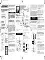
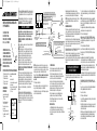
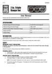
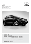
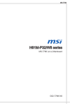
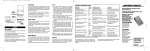
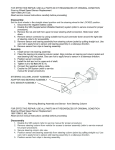
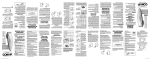
2:05 PM
Page 1
CONTROLS
OUTPUT CONTROL
SETUP
The Sync setting is shown as 10 through 90 with 10 being
the least aggressive and 90 being the most aggressive.
With the trailer connected press and hold the brake pedal,
the Display will show the Output setting.
The Sync adjustment has no effect on the manual control.
MORE OUTPUT
LESS OUTPUT
PUSH TO
APPLY BRAKES
SYNC CONTROL
pedal (trailer must be connected) and move the Sync Control
slightly. The display will change to the Sync mode.
OUTPUT / SYNC
DISPLAY
MANUAL CONTROL
The Sync Control would be adjusted for individual driver
preference or changing road conditions.
MANUAL CONTROL
The Manual Control is located on the front of the Brake
Control Unit at the right side.
MORE AGGRESSIVE BRAKING
LESS AGGRESSIVE BRAKING
OUTPUT CONTROL
The Output Control establishes the maximum amount of
power available to the trailer brakes.
As the Control is rotated up more power will be available
to the brakes when the brake pedal is pressed or the
manual control is used.
The Output Control would be adjusted during initial setup,
when trailer load changes, when different trailers are used
or to adjust for a change in road conditions.
The Output setting is shown on the digital display when a
trailer is connected and the brake pedal is pressed or the
Manual Control is actuated.
The Output setting is shown as 0 through 10 with 0 being
the minimum and 10 the maximum.
The Manual Control only applies the trailer brakes and would
be used during initial setup and in situations where it is
desirable to reduce speed slowly.
When the Manual Control is pushed to the left, the control
begins to apply the trailer brakes. The further to the left it is
pushed the harder the brakes are applied until the maximum
set by the Output Control is reached.
The Output setting will be shown on the display and can be
adjusted when using the Manual Control.
The Manual Control activates the tow vehicle and trailer stoplights.
SINGLE DECIMAL
CONTROL ACTIVATED
NO TRAILER CONNECTED
LEVEL
OUTPUT DISPLAY
CONTROL ACTIVATED
TRAILER CONNECTED
The Sync Control adjusts trailer brake aggressiveness.
The trailer brakes become more aggressive as the switch
is moved toward the front of the tow vehicle.
To view the Sync setting on the display, press the brake
ERROR DISPLAY
INTERNAL CONTROL ERROR
SEE TROUBLE SHOOTING GUIDE
LEVEL
SYNC CONTROL
The Sync Control is located on the left side of the Brake
Control Unit, forward of the mounting bracket.
LEVEL
LEVEL
SYNC DISPLAY
BRAKE PEDAL PUSHED
SYNC CONTROL ACTIVATED
TRAILER CONNECTED
OVER LOAD DISPLAY
SHORTED OR OVER LOADED
BRAKE CIRCUIT
SEE TROUBLE SHOOTING GUIDE
LEVEL
DISPLAY MODES
DIGITAL DISPLAY
The Digital display shows the Output setting when the
control is activated. It is used to setup and monitor the
Brake Control and can be used when trouble shooting.
TROUBLE SHOOTING GUIDE
Preliminary Adjustments
Adjust to 2.0 by turning the control up or down as needed.
While still holding the brake pedal move the Sync Control
slightly, the Display will change to the Sync setting.
Adjust to 40 by sliding the Sync Control ahead or back as
necessary.
TEST DRIVE
In an open area, such as a large parking lot, drive forward
and apply the trailer brakes using the Manual Control.
If the trailer brakes are weak adjust the Output Control up.
If the trailer brakes jerk or lockup adjust the Output Control
down.
Repeat this step until firm braking is felt with out jerking or
lockup.
Once the Output is set, drive forward and press the brake
pedal, the tow vehicle and trailer should make a smooth stop.
If the stop seems slow and more aggressive braking is
desired, move the Sync Control rearward while holding the
brake pedal.
If the stop seems too aggressive adjust the Sync Control
rearward while holding the brake pedal.
After making a Sync adjustment the Display will show the
setting until the brake pedal is released.
Make several stops at various speeds and adjust the Sync
until stops are smooth and firm. Slight adjustment of the
Output Control may also be desirable.
NOTE: If any problems occur during Setup refer to the
Trouble Shooting section of these instructions.
TEST WITHOUT TRAILER FIRST
CONDITION
WITHOUT TRAILER CONNECTED
3/6/03
WITH TRAILER CONNECTED
05500-037 2/6/03 English
DISPLAY
DECIMAL POINT DOES NOT LIGHT
WHEN BRAKE PEDAL OR MANUAL
CONTROL IS USED
DECIMAL POINT DOES NOT LIGHT
WHEN BRAKE PEDAL IS PUSHED
DOES LIGHT WITH MANUAL
DECIMAL ON ALL THE TIME
LEVEL
BLANK
LEVEL
LEVEL
PEDAL
MANUAL
LEVEL
DECIMAL ONLY
DISPLAY SHOWS OUTPUT
SETTING
DISPLAY SHOWS OL WHEN
ACTIVATED
DISPLAY SHOWS Er
LEVEL
PROBABLE CAUSES
POSSIBLE SOLUTION
NO POWER TO CONTROL, NO GROUND,
REVERSED BLACK AND WHITE WIRES,
CIRCUIT BREAKER BLOWN
CHECK AND REPAIR CONNECTIONS
REFER TO "WIRING" SECTION
NO CONNECTION OR INCORRECT
CONNECTION AT STOPLIGHT SWITCH,
BLOWN FUSE IN STOPLIGHT CIRCUIT
CHECK AND REPAIR CONNECTIONS
REFER TO "WIRING" SECTION,
CHECK STOPLIGHT CIRCUIT
RED WIRE CONNECTED TO THE WRONG
SIDE OF THE STOPLIGHT SWITCH OR
TO WRONG SWITCH (CRUISE CONTROL)
CHECK AND REPAIR CONNECTIONS
REFER TO "WIRING" SECTION
BRAKE CONTROL UNIT MISWIRED
CHECK AND REPAIR CONNECTIONS
REFER TO "WIRING" SECTION
SHORT IN BLUE WIRE CIRCUIT
LOCATE AND CORRECT SHORT
INTERNAL BRAKE CONTROL PROBLEM
RETURN UNIT TO DEALER FOR
EVALUATION
NO CONNECTION BETWEEN BRAKE CONTROL
AND BRAKES - BLUE WIRE CIRCUIT
CONFIRM CONNECTION TO TRAILER
CONNECTOR, CONFIRM CONNECTOR
TERMINAL POSITIONS, CHECK TRAILER
MISWIRED TRAILER CONNECTOR
CONFIRM TRAILER CONNECTOR
TERMINAL POSITIONS
OUTPUT SETTING
LEVEL
LEVEL
LEVEL
DECIMAL ONLY
NO TRAILER BRAKES, PEDAL
OR MANUAL
ELECTRONIC TRAILER
BRAKE CONTROL FOR
2, 4, 6 & 8 BRAKE
SYSTEMS
FLASHING OL
ERROR
NO TRAILER BRAKES, PEDAL
OR MANUAL
INSTRUCTIONS FOR THE INSTALLATION
AND OPERATION OF
LEVEL
IMPORTANT: READ AND
FOLLOW THESE INSTRUCTIONS CAREFULLY. KEEP THESE
INSTRUCTIONS IN YOUR TOW
VEHICLE FOR FUTURE REFERENCE.
OUTPUT SETTING
NO TRAILER BRAKES, PEDAL
OR MANUAL
SHORT OR OVERLOAD IN TRAILER BRAKES
TROUBLE SHOOT TRAILER BRAKE
CIRCUIT PER BRAKE MANUFACTURER'S
INSTRUCTIONS
INTERNAL BRAKE CONTROL PROBLEM
RETURN UNIT TO DEALER FOR
EVALUATION
MISWIRED TRAILER CONNECTOR
CHECK AND CORRECT CONNECTOR
WIRE POSITIONS
MISWIRED TRAILER CONNECTOR
CHECK AND CORRECT CONNECTOR
WIRE POSITIONS
LEVEL
FLASHING OL
NO TRAILER BRAKES, PEDAL
OR MANUAL
WEAK OR NO TRAILER BRAKES
LEVEL
ERROR
LEVEL
OUTPUT SETTING
TRAILER BRAKES ON ALL THE
TIME
LEVEL
BLANK
USAGE TIPS
control will not disengage "Cruise Control".
Light pressure on the brake pedal will activate the trailer's
brakes with no effect on the tow vehicle's brakes. This is
useful for gradual slowing on steep grades or before stops.
When Towing (in most applications) with Hazard Flashers
on the Digital Display will flash with the Hazard Flashers. If
the Brake Control is set aggressively pulsing may be felt in
the trailer brakes.
Periodic adjustment of the Sync and Output controls
may be necessary to correct for changing road conditions,
trailer loading, brake wear, and/or driver preference.
On some vehicles, operating the Brake Control's Manual
Installation of a Pulse Preventor will isolate the brake control from the flashers and eliminate the flash/pulse situation.
THIS PACKAGE INCLUDES:
(1) Brake Control Unit
(1) Mounting Bracket
(4) Mounting Screws
(1) Wire Tap Connector
(1) Warranty Card
TOOLS REQUIRED:
Assorted end wrenches
Drill with ¹⁄₈" bit
Wire connector crimp tool
Probe type circuit tester
Wire cutter/stripper
Screwdriver or ¹⁄₄" Nut Driver
MATERIAL REQUIRED:
10 Ga. wire
30 Amp auto-reset circuit breaker
Assorted ring terminal & butt connectors
4" cable ties (6-10)
Towing Products
47774 Anchor Court West
Plymouth, MI 48170
© TOWING PRODUCTS 2003
PRINTED IN CHINA
05500-037 1 of 3 rev. 2/6/03
Page 2
2. Hold the mounting bracket in the position selected and
mark hole locations through the slots in the bracket
12 VOLT BATTERY OF TOW VEHICLE
IMPORTANT: READ AND FOLLOW ALL WARNINGS AND
CAUTIONS ON TOW VEHICLE BATTERY
3. Using a 1/8" dia. bit, drill holes in the marked locations.
ANY ANGLE
UNDER DASH
WIRING
TOP OF DASH
VERTICAL
WARNING: Do not connect the black “BATTERY” wire to
the fuse panel or tie into accessory wiring. Connecting
to existing wiring may damage vehicle wiring and cause
trailer brake failure.
FOR TOW VEHICLES EQUIPPED WITH FACTORY TRAILER
TOWING PACKAGES:
Wire per tow vehicle manufacturer's instructions.
IMPORTANT: MAKE SURE AREA BEHIND PANEL IS CLEAR
BEFORE DRILLING.
USE BRACKET AS TEMPLATE TO MARK HOLE LOCATIONS.
DRILL (2) 1/8" DIA. HOLES AND MOUNT BRACKET WITH
SCREWS PROVIDED.
MOUNT BRAKE CONTROL TO BRACKET USING THE
REMAINING (2) SCREWS.
NOTE: Make sure that the tow vehicle's Brake Control
Battery Feed circuit is capable of carrying enough current to
supply trailer brake requirements (check tow vehicle manufacturer's instructions and trailer brake manufacturer's
information). If the circuit does not meet the trailer's
requirements, wire directly to the battery per steps 1
through 7.
FOR TOW VEHICLES WITHOUT FACTORY TRAILER
TOWING PACKAGES:
1. Disconnect the tow vehicle's negative (-) battery cable.
MOUNTING
B) The unit must be easily reached by the driver.
2. Mount a 30 Amp auto-reset circuit breaker as close to
the positive (+) battery terminal as possible. Using 10 Ga.
stranded wire and crimp type ring terminals connect the
"BATT" side of the circuit breaker to the positive battery terminal.
C) The area behind the mounting location must be clear
so nothing will be damaged when drilling.
NOTE: When passing wire through sheet metal always go
through an existing grommet, add a grommet or use
1. Determine a suitable mounting location.
A) The unit must be mounted securely to a solid surface.
DISCONNECT NEGATIVE (-)
CABLE BEFORE WIRING
BRAKE CONTROL UNIT
4. With a screwdriver or a 1/4" nut driver, secure the
bracket in place using (2) self tapping screws (provided).
Be careful not to strip the holes by over-tightening.
5. Mount the brake control unit in the bracket using the
other (2) self tapping screws as shown in the illustration.
9. Secure all loose wires with cable ties so that they will
not be damaged and reconnect battery. See vehicle's
owners manual for special re-connection instructions.
THIS ELECTRONIC BRAKE CONTROL IS FOR USE
ON 12 VOLT NEGATIVE GROUND SYSTEMS ONLY
USE 10 GA. WIRE
TRAILER
CONNECTOR
BUTT CONNECTORS
(NOT SUPPLIED)
BATT
BRAKE BLUE
BATTERY + BLACK
BRAKE CONTROL
STOPLIGHT RED
GROUND - WHITE
30A AUTO-RESET
CIRCUIT BREAKER
(NOT SUPPLIED)
WIRE TAP
(SUPPLIED)
IMPORTANT: DO NOT REVERSE BLACK AND
WHITE WIRE CONNECTIONS. DAMAGE TO
THE BRAKE CONTROL UNIT MAY OCCUR.
Without a trailer connected, push the brake pedal.
A single . (decimal point) should light up on the Display.
If the decimal point does not light or if OL or Er is shown
go to the Trouble Shooting section.
silicone rubber to insulate the wire from the hole.
3. Feed one black and one white, 10 Ga. stranded wire from
the Brake Control location to the tow vehicle's battery area.
4. Connect the black wire to the "AUX" side of the circuit
breaker with a ring terminal.
5. Connect the white wire to the negative battery post with
a ring terminal.
6 Attach the Control's black "BATTERY +" wire to the wire
(black) connected to the "AUX" side of the circuit breaker
using a butt connector.
7. Connect the control's white "GROUND" wire to the wire
(white) leading from the negative battery terminal with
another butt connector.
IMPORTANT: A brake control that is not properly grounded
may operate intermittently or not at all. Recheck to make
sure that the white "GROUND -" wire is connected to the (-)
negative battery terminal and that the black "BATTERY +"
wire is attached to the (+) positive battery terminal.
ONLY CONNECT
RED WIRE
WHEN NEEDED
IMPORTANT: READ AND FOLLOW
ALL WARNINGS AND CAUTIONS
SHOWN ON BATTERY
ONLY CONNECT BULB
TO NEGATIVE TERMINAL
WHEN NEEDED
BLUE WIRE
STANDARD 1156
AUTOMOTIVE BULB
BENCH TEST INSTRUCTIONS
SPECIAL INSTRUCTIONS FOR FORD E AND F SERIES TRUCKS
AND VANS, 1989 - 91, WITH ANTI-LOCK BRAKES
DO NOT CONNECT TO STOPLIGHT SWITCH
ON THESE VEHICLES
1. Wire as shown at right. Set the Output control to
maximum (+) and set the Sync control to minimum (-).
LIGHT GREEN WIRE
STOPLIGHT SWITCH
CONNECT TO COLD SIDE
(ON ONLY WHEN PEDAL IS PUSHED)
WHITE WIRE IS
CONNECTED TO
NEGATIVE -
10.Test installation:
USE 10 GA. WIRE
AUX
12 VOLT BATTERY OF TOW VEHICLE
BLACK WIRE IS
CONNECTED TO
POSITIVE +
WHITE WIRE
2:05 PM
RED WIRE
3/6/03
BLACK WIRE
05500-037 2/6/03 English
TURN SIGNAL HARNESS
CONNECTOR UNDER DASH
NEAR STEERING COLUMN
SPLICE RED STOPLIGHT WIRE TO LIGHT GREEN
WIRE USING THE WIRE TAP CONNECTOR SUPPLIED
NOTE: If at any time during the bench test, the display shows
OL make sure that the blue "BRAKE" wire is not shorted to the
"-" battery terminal or the white "BATTERY -" wire.
USE A SOCKET OR SOLDER
WIRES TO BULB
SYNC CONTROL
OUTPUT CONTROL
MORE OUTPUT
LESS OUTPUT
MANUAL CONTROL
8. For tow vehicles other than 1989-91 Ford E and F
series trucks and vans:
If at any time, the display shows Er return the unit to your
Draw-Tite dealer for further evaluation.
Determine which side of the stoplight switch is the cold
side. To determine the cold side probe the terminals of the
switch with a test light until one is found that is only on
when the brake pedal is depressed.
2. Test "Standby Condition"
Slowly move the Sync Control to maximum (+). The
display should change to Sync mode and count up to 90.
Hold the red "STOPLIGHT" wire on the "+" battery terminal. The
display should show a single . (decimal point). This indicates
correct wiring and that the control is ready.
Disconnect and reconnect the red wire. The bulb should
light brightly with no delay and the Display should read 10.
Using the wire tap provided, splice the brake control's red
"STOPLIGHT" wire to the attached to the cold side of the
stoplight switch as determined above.
Disconnect the red "STOPLIGHT" wire from the battery.
For 1989-91 Ford E and F series trucks and vans with
anti-lock brakes:
Firmly ground the light bulb to the "-" terminal of the battery.
Find the crescent shaped connector located on the steering
column (turn signal harness). The connector has two rows
of wires, one row has four wires (inside row) the other has
seven.
The display should step up to 10 and the bulb should start
out dim and slowly get brighter (unhook and re-attach the
red wire as many times as necessary to confirm this)
3. Test Brake Pedal Activation
Re-attach the red "STOPLIGHT" wire to the "+" battery terminal.
The wire needed is the light green wire, second in from the
row of seven (see wiring diagram above).
With the red wire still hooked up, slowly move the Output
Control down to (-). The display should count down to 0
and the bulb should dim and go off.
Using the wire tap provided, splice the brake control's red
"STOPLIGHT" wire to the light green wire.
Slowly move the Output Control back up to (+), the Display
should go back to 10 and the bulb should return to full brightness.
Disconnect the red wire.
4. Test Manual Activation
With the Output Control still set at maximum, slowly
activate the Manual Control button.
The bulb should start to dim and get brighter and the display should count up to 10 as the Manual Control is pushed.
While holding the Manual Control all the way in, rotate the
Output Control up and down. As the output changes the
bulb should go bright and dim and the display should
read 0 to 10.
5. Defective Unit
If the Brake Control unit does not function as described,
return it for service or replacement.
Page 1
4. Au moyen d’un tournevis ou d’un tourne-écrous de 1/4", fixez
le support en place avec les deux vis auto taraudeuses (fournies)
Faites attention de ne pas foirer les trous en serrrant trop.
INSTRUÇTIONS POUR L’INSTALLATION
ET L’OPÉRATION DU
CONTRÔLE ÉLECTRONIQUE DE
FREINS POUR REMORQUES À
SYSTÈMES DE 2, 4, 6, ET 8 FREINS
IMPORTANT: LISEZ ET
SUIVEZ TOUTES LES
INSTRUCTIONS FIDÈLEMENT.
GARDEZ-LES DANS VOTRE
VÉHICULE REMORQUEUR POUR
RÉFÉRENCE ULTÉRIEUR.
CE NÉCESSAIRE
CONTIENT:
MATÉRIEL REQUIS -
Néc. de câblage pour contrôle
(1) Dispositif de contrôle de freins de freins ou:
(1) Support de montage
Câblage de calibre 10
(4) Vis pour le montage
Disjoncteur à réenclenchement
(1) Connecteur volant
automatique de 30 A
(1) Fiche de garantie
Cosses à sertir et manchons
connecteurs divers
OUTILS REQUIS:
Colliers de serrage de 4” (6-10)
Ciés diverses
Perceuse avec foret de 1/8”
Pinces pour connecteurs
électriques
Towing Products
Vérificateur de circuit
47774 Anchor Court West
Pinces coupe-fils/à dénuder
Plymouth, MI 48170
Tournevis ou tourne-écrous
de 1/4”
© TOWING PRODUCTS 2003
PRINTED IN CHINA
05500-037 2 of 3 rev. 2/6/03
IMPORTANT: LISEZ TOUS LES AVERTISSEMENTS ET PRENEZ TOUTES LES
PRÉCAUTIONS IMPRIMÉES SUR LA BATTERIE DU VÉHICULE REMORQUEUR.
5. Montez le contrôle de freins dans le support au moyen des
deux autres vis auto taraudeuses comme montré dans
l’illustration.
DÉBRANCHEZ LE CÂBLE NÉGATIF (-)
AVANT DE FAIRE LE CÂBLAGE DU
DISPOSITIF DE CONTRÔLE DE FREINS
SECTION 2 - CÂBLAGE
AVERTISSEMENT: Ne pas brancher le fil noir "BATTERY" à la
boîte de fusibles ou connecter au câblage auxiliaire. Un
branchement au câblage existant pourrait endommager le
câblage du véhicule ou provoquer une panne des freins de
la remorque.
POUR VÉHICULES REMORQUEURS ÉQUIPÉS D’UN
DISPOSITIF DE REMORQUAGE INSTALLÉ EN USINE:
BATT
UTILISEZ DU CÂBLE DE CALIBRE 10
FREIN, BLEU
BATTERIE (+) NOIR
AUX
INSTRUCTIONS PARTICULIÈRES: POUR LES
FOURGONNETTES ET CAMIONS FORD DE SÉRIES
E ET F 1989-1991 AVEC FREINS ANTIBLOCAGE,
NE CONNECTEZ PAS À L'INTERRUPTEUR DES FEUX D'ARRÊT
INTERRUPTEUR DES FEUX D'ARRÊT
BRANCHEZ AU CÔTÉ MORT
(EN MARCHE SEULEMENT SI ON APPUIE
SUR LA PÉDALE DE FREIN)
NOTE: Assurez-vous que le circuit d’alimentation de la batterie
au contrôle de freinage du véhicule remorqueur puisse supporter assez de courant pour rencontrer les exigences des
freins de la remorque (vérifiez les instructions du manufacturier du véhicule remorqueur et l’information du manufacturier
des freins de la remorque). Si le circuit ne peut satisfaire aux
exigences du fabricant, posez les fils directement à la batterie
en suivant les étapes 1 à 8.
Si ce point n’apparaît pas, ou si OL ou Er apparaissent, allez à la
section Localisation de la panne.
POUR LES VÉHICULES SANS DISPOSITIF DE REMORQUAGE
INSTALLÉ EN USINE. VOIR LA FIG. 2:
SECTION 3 - CONTRÔLES
NOTE: lorsque vous passez des fils au travers de la tôle,
passez-les toujours dans un passe-fil existant ou ajoutez-en un
ou passez-les dans du silicone pour les isoler du trou.
CONNECTEUR DU FAISCEAU DES
CLIGNOTANTS SOUS LE TABLEAU DE BORD
PRÈS DE LA COLONNE DE DIRECTION.
ÉPISSEZ LE CÂBLE ROUGE DU FEU D'ARRÊT AU CÂBLE
VERT PÂLE AU MOYEN DU CONNECTEUR VOLANT FOURNI
Fig. 2a
Le réglage de sortie sera montré dans le tableau et peut être
ajusté lorsque le contrôle manuel est utilisé.
Le tableau digital montre le réglage du contrôle de sortie
lorsque le contrôle est activé. II est utilisé pour fixer et superviser le dispositif de contrôle de freinage et aussi pour localiser
une panne.
Fig. 3
PLUS DE PUISSANCE DE SORTIE
MOINS DE PUISSANCE DE SORTIE
APPUYEZ POUR FAIRE
ACTIVER LES FREINS
CONTRÔLE SYNC
1. Posez les fils tel qu’indiqué ci-dessous. Réglez le contrôle de
sortie à maximum (+) et le contrôle "Sync" à minimum (-).
NOTE: si le tableau montre OL peu importe quand durant
l’installation, assurez-vous que le câble bleu "BRAKE" n’est pas
court-circuité à la borne négative de la batterie ou au câble
blanc "BATTERY –".
SEUL POINT
CONTROLE ACTIVÉ
SANS REMORQUE
TABLEAU DE SORTIE
CONTRÔLE ACTIVE
AVEC REMORQUE
CONTRÔLE MANUEL
LEVEL
Fig. 4
CÂBLE BLANC EST
CONNECTÉ À LA
BORNE NÉGATIVE -
CÂBLE NOIR EST
CONNECTE À LA
BORNE POSITIVE +
CONNECTEZ LE CÂBLE
ROUGE SEULEMENT
QUAND IL Y A BESOIN
CONNECTEZ LA LAMPE À LA
BORNE NÉGATIVE SEULEMEN
QUAND IL Y A BESOIN.
CÂBLE BLEU
LEVEL
LAMPE STANDARD
D'AUTO #1156
TABLEAU DE SURCHARGE
COURT-CIRCUIT OU SURCHARGE
DU CIRCUIT DE FREINAGE
VOIR LOCALISATION DE LA PANNE
UTILISEZ UNE DOUILLE OU
SOUDEZ LES CÂBLES À LA LAMPE
CONTRÔLE SYNC
TABLEAU D'ERREUR
ERREUR INTERNE DU CONTRÔLE
VOIR LOCALISATION DE LA PANNE
LEVEL
TABLEAU DE SYNC
PÉDALE DE FREIN APPUYÉE
CONTRÔLE DE SYNC ACTIVÉ
AVEC REMORQUE
BATTERIE DE 12 V DU VÉHICULE
REMORQUEUR
IMPORTANT: LISEZ TOUS LES
AVERTISSEMENTS ET PRENEZ
TOUTES LES PRÉCAUTIONS
IMPRIMÉES SUR LA BATTERIE
LEVEL
TABLEAU DE
SORTIE/SYNC
FREINAGE PLUS AGRESSIF
FREINAGE MOINS AGRESSIF
Pour déterminer si le dispositif de contrôle de freins fonctionne
adéquatement, suivez ces étapes pour tester le dispositif en
atelier.
Le contrôle manuel actionne les feux d’arrêt du véhicule
remorqueur et de la remorque.
TABLEAU DIGITAL
CONTRÔLE DE SORTIE
3. Installez un disjoncteur à réenclenchement automatique de
30 A aussi près que possible de la borne positive (+) de la batterie. Au moyen d’un câble de calibre 10 et d’une cosse à sertir
fermée, branchez le côté "BATT" du disjoncteur au câble positif
de la batterie.
INSTRUCTIONS POUR
TESTS EN ATELIER
CONNECTEUR VOLANT
(FOURNI)
IMPORTANT: N'INVERSEZ PAS LES CONNEXIONS DU
CÂBLE NOIR ET DU CÂBLE BLANC! VOUS
ENDOMMAGERIEZ LE DISPOSITIF DE CONTRÔLE DE FREINS
Fig. 2
Lors de remorquages (dans la plupart des cas) avec les signaux
d’urgence en marche, le tableau clignotera en même temps que
les signaux d’urgence. Si le contrôle de frein est réglé pour
freinage ferme, on peut ressentir des impulsions dans les freins
de la remorque. En ce cas, utilisez Dispositif anti-pulsations.
CONTRÔLE DE FREINS.
FEU D'ARRÊT, ROUGE
MASSE (-) BLANC
DISJONCTEUR À
REENCLENCHEMENT
AUTOMATIQUE DE 30 A (NON FOURNI)
FIL VERT PÂLE
2. Débranchez le câble négatif (-) de la batterie du véhicule
remorqueur.
CONNECTEUR
POUR REMORQUE
MANCHONS CONNECTEURS
(NON FOURNIS)
UTILISEZ DU CÂBLE
DE CALIBRE 10
Posez les fils selon les directives du manufacturier du véhicule.
1. Déterminez quel est le côté mort de l’interrupteur des
feux d’arrêt. Pour le trouver, faites un essai sur les bornes de
l’interrupteur au moyen d’une lampe d’essai jusqu’à ce que
vous trouviez une borne qui allume seulement lorsqu’on appui
sur la pédale de frein. Marquez le câble mort.
L’ajustement périodique des contrôles de sortie et "sync" peut
être nécessaire pour s’adapter aux changement des conditions
routières, de chargements de la remorque, de l’usure des freins
ou des préférences du chauffeur. Sur certains véhicules, le
contrôle manuel des freins ne désengagera pas le pilote
automatique.
CE CONTRÔLE DE FREINS ÉLECTRONIQUE NE DEVRA ÊTRE UTILISÉ QUE SUR
DES SYSTÈMES DE 12 VOLTS AVEC MISE À LA TERRE NÉGATIVE SEULEMENT
BATTERIE 12 DU VÉHICULE REMORQUEUR
CÂBLE BLANC
2:07 PM
CÂBLE NOIR
3/6/03
CÂBLE ROUGE
05500-037 2/6/03 French
CONTRÔLE DE SORTIE
LEVEL
MODES DU TABLEAU
PLUS DE PUISSANCE SE SORTIE
MOINS DE PUISSANCE DE SORTIE
CONTRÔLE MANUEL
Si n’importe quand au cours de l’installation, les lettres Er
apparais sent, renvoyez le dispositif de contrôle de freins à
votre concessionnaire pour évaluation.
2. Vérifiez la condition de réserve.
Tout en surveillant la lampe d’essai, tenez le câble rouge
"STOPLIGHT" sur la borne positive (+) de la batterie. Le tableau
devrait afficher un point (point décimal). Ceci indique un
câblage correct et que le contrôle de freins est prêt.
Débranchez le fil rouge "STOPLIGHT" de la batterie.
3. Vérifiez l’activation de la pédale de frein
Reliez fermement l’ampoule à la borne "-" de la batterie.
Rattachez le fil rouge "STOPLIGHT" à la borne "+" de la batterie.
Le tableau devrait remonter à 10. et l’ampoule devrait s’allumer
d’abord faiblement puis de plus en fort (enlevez et rattachez le
fil rouge autant de fois qu’il le faudra pour confirmer ce résultat).
En maintenant le fil rouge toujours relié, déplacez lentement le
contrôle de sortie vers le bas (-). Le tableau devrait afficher 0.0
et l’ampoule devrait faiblir et disparaître.
Lentement, ramenez le contrôle de sortie vers (+), le tableau
devrait revenir à 10. et l’ampoule devrait revenir à sa pleine
force.
Déplacez lentement le contrôle "sync" à maximum (+). Le
tableau devrait passer en mode "sync" et compter jusqu’à 9o.
Déconnectez et reconnectez le fil rouge. L’ampoule devrait
éclairer à pleine capacité immédiatement et le tableau afficher
10..
Débranchez le fil rouge.
4. Vérifiez l’activation manuelle
Tout en maintenant le contrôle de sortie à maximum, activez
lentement le bouton de contrôle manuel.
La lampe d’essai devrait éclairer d’abord faiblement, puis de
plus en plus fort et le tableau devrait compter jusqu’à 10. au fur
et à mesure que le contrôle manuel est poussé.
Tout en maintenant le contrôle à pleine puissance, faites tourner
le contrôle de sortie de bas en haut. Selon le mouvement, l’ampoule devrait briller et s’affaiblir et le tableau afficher 0.0 à 10..
5. Dispositif défectueux
Si le dispositif de contrôle de freins ne fonctionne tel qu’ex
pliqué, retournez-le pour réparation ou pour le faire remplacer.
2:07 PM
Page 2
SECTION 1 - MONTAGE
4. Acheminez un fil blanc et un fil noir de calibre 10 à partir
de l’emplacement du contrôle de freins jusqu’à l’emplacement
de la batterie du véhicule remorqueur.
5. Branchez le câble noir au côté "AUX" du disjoncteur au
moyen d’une cosse à sertir fermée.
EN DESSOUS DU TABLEAU DE BORD
N'IMPORTE QUEL ANGLE
Fig. 1
EN DESSUS DU TABLEAU DE BORD
VERTICAL
IMPORTANT: AVANT DE PERCER, ASSUREZ-VOUS QUE L'ESPACE
DERRIERE LE PANEL SOIT LIBRE!
UTILISEZ LE SUPPORT EN GUISE DE MODELE POUR MARQUER
L'EMPLACEMENT DES TROUS.
PERCEZ DEUX TROUS DE 1/8" DE DIAMETRE ET MONTEZ LE
SUPPORT AVEC LES VIS FOURNIES.
MONTEZ LE CONTRÔLE DE FREINS SUR LE SUPPORT AU
MOYEN DES DEUX VIS RESTANTES.
1. Choisissez un emplacement d’installation convenable
(Voir la Fig. 1).
A) Le dispositif doit être solidement fixé à une surface solide.
B) Le chauffeur doit avoir un accès facile au dispositif.
C) L’espace derrière l’emplacement doit être libre de faÇon à ce
que rien ne soit endommagé lors du perÇage.
2. Tenez le support de montage dans la position choisie et
marquez l’emplacement des trous au travers des trous oblongs
dans le support.
3. Au moyen d’un foret de 1/8" de diamètre, percez les trous dans
les emplacements marqués.
6. Branchez le câble blanc au câble négatif de la batterie au
moyen d’une cosse à sertir fermée.
7. Reliez le câble noir du contrôle de freins "BATTERY +" au
câble (noir) branché à la borne "AUX" du disjoncteur au
moyen d’un manchon connecteur.
8. Connectez le câble blanc "GROUND" du contrôle de freins
au câble blanc provenant du câble négatif de la batterie au
moyen d’un autre manchon connecteur.
IMPORTANT: un contrôle de freins qui n’est pas bien mis à la
terre peut opérer par intermittences ou pas du tout. Revérifiez
afin de vous assurer que le câble blanc "GROUND" est
connecté au câble négatif de la batterie et que le câble noir
"BATTERY +" est relié au câble positif de la batterie.
9. Pour tous les véhicules remorqueurs sauf les
fourgonnettes et les camions Ford, Séries E et F, 1989-91:
Au moyen du connecteur volant fourni, épissez le câble rouge
"STOPLIGHT" du contrôle de freins au câble relié au côté mort
de l’interrupteur des feux d’arrêt, tel que decrit à l’étape 1.
Allez à l’étape 10.
Pour les fourgonnettes et camions Ford Série E et F de
1989-91 avec freins antiblocage: Voir la Fig. 2a:
Repérez le connecteur en forme de croissant sur la colonne
de direction (faisceau de clignotants). II y a 2 rangées de
câbles dans ce connecteur, une rangée de 4 câbles (rangée
intérieure) et l’autre en a 7. Vous avez besoin du vert pâle qui
est le deuxième à partir de la gauche dans la rangée de 7
câbles.
Au moyen du connecteur volant fourni, épissez le câble rouge
"STOPLIGHT" du contrôle de freins au câble vert pale.
10. Branchez le câble bleu "BRAKE" du contrôle de freins au
câble de freins de remorque.
11. Fixez tous les câbles libres au moyen des colliers de
serrage de façon à ce qu’ils ne soient pas endommagés.
Rebranchez la batterie. Voir le manuel de propriétaire du
véhicule pour les instructions particulières de rebranchement.
12. Faites un essai de l’installation: Sans remorque attachée,
appuyez sur la pédale de frein. Un seul. (point décimal)
devrait s’allumer dans le tableau.
CONTRÔLE DE SORTIE
RÉGLAGES
Le contrôle de sortie définit la quantité maximum de courant
disponible pour les freins de la remorque.
Avec une remorque attachée, pressez et tenez la pédale de frein,
le tableau affichera le réglage du contrôle de sortie.
Plus le contrôle est tourné vers le haut, plus il y a de courant
disponible pour les freins lorsqu’on appuie sur la pédale de
freins ou que le contrôle manuel est utilisé.
Ajustez à 2.0 en tournant le contrôle vers le haut ou vers le bas,
au besoin.
II faudra ajuster le contrôle de sortie si le chargement de la
remorque augmente, lorsque différentes remorques sont tirées
ou selon les conditions routières.
Le réglage de sortie est montré dans le tableau digital
lorsqu’une remorque est attachée et qu’on appuie sur la pédale
de frein ou que le contrôle manuel est activé.
Le réglage de sortie va de 0.0 à 10., 0.0 étant le minimum et
10. le maximum.
Tout en maintenant le pédale de frein, déplacez légèrement le
contrôle "sync", le tableau passera en mode "sync".
ESSAI SUR LA ROUTE
Dans un espace dégagé, comme un grand stationnement,
avancez et arrêtez au moyen du contrôle manuel.
LE POINT DÉCIMAL N'APPARAÎT PAS
LORSQUE LA PÉDALE DE FREIN EST ACTIVÉE
MAIS ALLUME EN CONTRÔLE MANUEL
Le contrôle "sync" est situé du côté gauche du dispositif de
contrôle de freins, devant le support de montage.
Si les freins de la remorque bloquent ou sautent, ajustez le
contrôle de sortie vers le bas.
Le contrôle "sync" ajuste l’agressivité du freinage.
Répétez ces étapes jusque les freins soient fermes sans sauter
ni bloquer.
Le réglage "sync" est montré de 1o à 9o, 1o étant le freinage le
moins agressif et 9o le freinage le plus agressif.
L’ajustement "sync" n’a aucun effet sur le contrôle manuel.
II faudra ajuster le contrôle "sync" selon les préférences de
chaque chauffeur ou selon les conditions routières.
CONTRÔLE MANUEL
Le contrôle manuel est situé du côté droit, sur le devant du
dispositif de contrôle de frein.
Le contrôle manuel n’applique que les freins de la remorque. II
devrait être utilisé pendant le réglage initial et dans les situations ou il faut lentement réduire la vitesse.
PROBLÈME
LE POINT DÉCIMAL N'APPARAÎT PAS
LORSQUE LA PÉDALE DE FREIN OU LE
CONTRÔLE MANUEL SONT ACTIVÉS
CONTRÔLE "SYNC"
Pour voir le réglage du contrôle "sync" sur le tableau, appuyez
sur la pédale de frein (la remorque doit être attachée) et
déplacez le contrôle "sync" légèrement. Le tableau passera en
mode "sync".
TESTER SANS REMORQUE D'ABORD
Ajustez à 4o en glissant le contrôle "sync" vers l’avant ou vers
l’arrière, au besoin.
Si les freins de la remorque sont mous, ajustez le contrôle de
sortie vers le haut.
Les freins de la remorque sont plus agressifs selon que
l’interrupteur est déplacé vers l’avant du véhicule remorqueur.
GUIDE DE LOCALISATION DE LA PANNE
SANS REMORQUE
3/6/03
LE POINT DÉCIMAL APPARAÎT TOUT
LE TEMPS
LE TABLEAU AFFICHE LE RÉGLAGE DU
CONTRÔLE DE SORTIE
TABLEAU
LEVEL
BLANC
LEVEL
LEVEL
PÉDALE
MANUEL
LEVEL
POINT DÉCIMAL SEUL
LEVEL
CAUSES PROBABLES
SOLUTION POSSIBLE
PAS DE COURANT AU CONTRÔLE, PAS DE MISE
À LA TERRE, CONNEXIONS INVERSÉES DES
CÂBLES NOIR ET BLANC, DISJONCTEUR SAUTÉ
VÉRIFIEZ ET RÉPAREZ LES CONNEXIONS, RÉFÉREZ
RÉFÉREZ À LA SECTION CÂBLAGE
PAS DE CONNEXION OU MAUVAISE CONNEXION
DE L'INTERRUPTEUR DE FEUX D'ARRÊT FUSIBLE
SAUTÉ DANS LE CIRCUIT DES FEUX D'ARRÊT
VÉRIFIEZ ET RÉPAREZ LES CONNEXIONS,
À LA SECTION CÂBLAGE. VÉRIFIEZ LE CIRCUIT
DES FEUX D'ARRÊT
LE FIL ROUGE EST BRANCHÉ AU MAUVAIS CÔTÉ
DE L'INTERRUPTEUR DE FEUX D'ARRÊT OU AU
MAUVAIS INTERRUPTEUR (PILOTE AUTOMATIQUE)
VÉRIFIEZ ET RÉPAREZ LES CONNEXIONS, RÉFÉREZ
RÉFÉREZ À LA SECTION CÂBLAGE
LES FILS DU DISPOSITIF DE CONTRÔLE DE
FREINS SONT MAL PLACÉS
VÉRIFIEZ ET RÉPAREZ LES CONNEXIONS, RÉFÉREZ
RÉFÉREZ À LA SECTION CÂBLAGE
COURT-CIRCUIT DANS LE CIRCUIT DU FIL BLEU
RÉPEREZ ET CORRIGEZ LE COURT-CIRCUIT
PROBLÈME INTERNE DU CONTRÔLE DE FREINS
RENVOYEZ LE DISPOSITIF AU
CONCESSIONNAIRE POUR ÉVALUATION
PAS DE CONNEXION ENTRE LE CONTRÔLE DE
FREINS ET LES FREINS-CIRCUIT DU FIL BLEU
CONFIRMEZ LA CONEXION ET LES POSITIONS
DES BORNES DU CONNECTEUR DE L
REMORQUE, VÉRIFIEZ LA REMORQUE
LES FILS DU CONNECTEUR DE LA REMORQUE
SONT MAL POSÉS
CONFIRMEZ LA CONEXION ET LES POSITIONS
DES BORNES DU CONNECTEUR DE LA REMORQUE
COURT-CIRCUIT OU SURCHARGE DES FREINS
DE LA REMORQUE
LOCALISEZ LA PANNE DES FREINS DE LA
REMORQUE SELON LES INSTRUCTIONS
DU FABRICANT
PROBLÈME INTERNE DU CONTRÔLE DE FREINS
RENVOYEZ LE DISPOSITIF AU
CONCESSIONNAIRE POUR ÉVALUATION
LES FILS DU CONNECTEUR DE LA REMORQUE
SONT MAL POSÉS
VÉRIFIEZ ET CORRIGEZ LES POISTIONS DES
FILS DANS LE CONNECTEUR
LES FILS DU CONNECTEUR DE LA REMORQUE
SONT MAL POSÉS
VÉRIFIEZ ET CORRIGEZ LES POISTIONS DES
FILS DANS LE CONNECTEUR
RÉGLAGE DE SORTIE
LE TABLEAU AFFICHE OL LORSQU'ACTIVÉ
LEVEL
OL CLIGNOTANT
Une fois que le contrôle de sortie est ajusté, avancez et appuyez sur
la pédale de frein, le véhicule remorqueur et la remorque devraient
arrêter en douceur.
Si le freinage semble long et qu’une action plus agressive est
souhaitable, déplacez le contrôle "sync" vers l’indicateur positif (+)
tout en tenant la pédale de frein.
Si le freinage semble trop rapide, ajustez le contrôle "sync" vers l’indi
cateur négatif (-) tout en appuyant sur la pédale de frein.
Aprés avoir ajusté le contrôle "sync", le tableau affichera le réglage
jusqu’à ce qu’on relâche la pédale de frein.
Effectuez plusieurs arrêts à des vitesses différentes et ajustez le cont
rôle "sync" jusqu’à ce que les arrêts soient doux et fermes. II faudra
peut-être aussi ajuster légèrement le contrôle de sortie.
NOTE: Si des problèmes surgissent pendant les réglages, référezvous à la section "localisation de la panne" de cette brochure.
LE TABLEAU AFFICHE Er
LEVEL
ERREUR
PAS DE FREINS SUR LA REMORQUE
PÉDALE OU MANUEL
LEVEL
POINT DÉCIMAL SEUL
AVEC REMORQUE
05500-037 2/6/03 French
PAS DE FREINS SUR LA REMORQUE
PÉDALE OU MANUEL
LEVEL
RÉGLAGE DE SORTIE
PAS DE FREINS SUR LA REMORQUE
PÉDALE OU MANUEL
LEVEL
OL CLIGNOTANT
PAS DE FREINS SUR LA REMORQUE
PÉDALE OU MANUEL
LEVEL
ERREUR
FREINS MOUS OU ABSENTS
LEVEL
RÉGLAGE DE SORTIE
FREINS AVTIVÉS TOUT LE TEMPS
LEVEL
TRUCS
Une pression légère sur la pédale de freins n’aura que peu ou pas
d’effet sur les freins du véhicule remorqueur. Ceci est utile pour
Lorsque le contrôle manuel est poussé vers la gauche, il com
mence à opérer sur les freins de la remorque. Plus il est poussé ralentir graduellement dans les pentes abruptes ou avant d’arrêter.
vers la gauche, plus le freinage sera ferme, jusqu’à atteindre la
puissance maximum fixée par le réglage du contrôle de sortie.
BLANC
Page 1
4. Con un destornillador o un dado de 1/4", asegure el soporte
en su lugar usando (2) tornillos autoroscantes (se proveen).
Tenga cuidado de no barrer la rosca al apretar los tornillos.
INSTRUCCIONES PARA LA INSTALACIÓN
Y OPERACIÓN DEL
CONTROL DE FRENO
ELECTRÓNICO PARA
REMOLQUES CON SISTEMAS
DE 2, 4, 6 & 8 FRENOS
IMPORTANTE: LEA Y SIGA
CUIDADOSAMENTE ESTAS
INSTRUCCIONES. GUARDE
ESTAS INSTRUCCIONES EN SU
VEHÍCULO DE REMOLQUE PARA
REFERENCIA FUTURA.
ESTE PAQUETE INCLUYE: MATERIALES NECESARIOS (1) Unidad de Control de Freno
(1) Soporte de Montaje
(4) Tornillos de Montaje
(1) Conector a Corriente
(1) Tarjeta de Garantía
HERRAMIENTAS
NECESARIAS:
Llaves de diferentes calibres
Taladro con mecha de 1/8”
(3,175 mm)
Herramienta para plegar
conectores de cable
Probador de circuitos con
probadores
Cortador/pelador de cables
Destornillador o dado de 1/4”
(6,35 mm)
Joego de Cables para Control de
Freno o:
Cable de calibre 10
Cortacircuitos de tipo de reposición
de 30 amperios
Varios conectores dobles y de anillo
(6-10) Amarres de cable de 4”
(101-6 mm)
Towing Products
47774 Anchor Court West
Plymouth, MI 48170
© TOWING PRODUCTS 2003
PRINTED IN CHINA
05500-037 3 of 3 rev. 2/6/03
BATERÍA DE 12V DEL VEHÍCULO DE REMOLQUE
IMPORTANTE: Lea y siga todas las advertencias y
precauciones impresas en la baterÍa del vehÍculo de remolque
5. Instale la unidad de control de freno en el soporte usando
los otros (2) tornillos autoroscantes, asi como se ilustra.
ADVERTENCIA: No conecte el cable negro "BATTERY" al
DISCONECTE EL CABLE NEGATIVO (-)
ANTES DE CONECTAR LOS CABLES DE
LA UNIDAD DE CONTROL DE FRENO
SECCIÓN 2 - CABLEADO
panel de fusibles o al corriente del cableado de accesorios.
Al conectarlo al cableado existente puede dañar el cableado
del vehículo y causar fallas en los frenos del remolque.
EN VEHÍCULOS EQUIPADOS CON EQUIPO DE REMOLQUE
DE FÁBRICA:
Haga el cableado de acuerdo a las instrucciones del fabricante
del vehículo de remolque.
NOTA: Asegúrese de que el circuito que provee voltaje de la
Batería al Control de Freno es capaz de transportar el monto
de corriente que los frenos del remolque requieren (revise las
instrucciones del fabricante del vehículo de remolque y
también las instrucciones del fabricante de los frenos del
remolque). Si el circuito no es capaz de transportar la
corriente que los frenos del remolque necesitan, conecte un
cable directo a la batería siguiendo los pasos del 1 al 8.
EN VEHICULOS QUE NO TIENEN EQUIPO DE REMOLQUE DE
FÁBRICA: VEA LA FIG.2
1. Determine cuál lado (terminal) del interruptor de la luz de
freno es el lado muerto. Para determinar el lado muerto, use
una luz de prueba, conéctela a un terminal del interruptor y
presione el pedal del freno, repita este procedimiento en el
otro terminal. El lado muerto será aquel terminal en el cual la
luz se encienda cuando el pedal de freno esté presionado.
2. Desconecte el terminal negativo (-) de la batería del
vehículo.
3. Instale un cortacircuitos de tipo de reposición de 30
amperios tan cerca como sea posible al terminal positivo (+)
de la batería. Use un cable de cordón de calibre 10 y pliegue
(2) terminales de anillo al mismo. Use este cable para conectar
el lado que dice "BATT" del cortacircuitos al cable positivo (+)
de la batería
USE CABLE DE CALIBRE 10
USE CABLE DE CALIBRE 10
CONNECTOR DEL
REMOLQUE
CONECTORES DOBLES
(NO SE PROVEE)
BATT
FRENO AZUL
BATERÍA (+) NEGRO
AUX
CONTROL DE FRENO
LUZ DE FRENO ROJO
TIERRA (-) BLANCO
CORTACIRCUITOS DE TIPO DE
REPOSICIÓN DE 30 AMPERIOS
(NO SE PROVEE)
CONECTOR A CORRIENTE
(SE PROVEE)
INSTRUCCIONES ESPECIALES PARA CAMIONES Y CAMIONETAS
CERRADAS FORD (1989-1991) CON FRENOS ANTIBLOQUEANTES
EN ESTOS VEHÍCULOS NO CONECTE NADA AL INTERRUPTOR
DE LA LUZ DE FRENO
IMPORTANTE: ¡NO INTERCAMBIE LAS CONEXIONS DE LOS CABLES
BLANCO Y NEGRO! Esto dañara la unidad de control de freno.
CABLE VERDE CLARO
INTERRUPTOR DE LA LUZ DE FRENO
CONECTE AL LADO MUERTO
(SE ENCIENDE SOLO CUANDO EL PEDAL ES PRESIONADO)
NOTA: Cuando pase un cable a través de un agujero en una
lámina metálica, use siempre un agujero blindado existente, si
es necesario hacer un nuevo agujero, use goma de silicio o un
borde de goma para aislar el cable del borde metálico.
Reconecte la batería. Refiérase al manual de instrucciones de
vehículo para obtener las instrucciones especiales de
reconexión.
12. Prueba de la Instalación:
Sin un remolque conectado, presione el pedal de freno. Solo
un . (punto decimal) debe aparecer en la Pantalla.
Si el punto decimal no aparece o si OL o Er aparecen, vaya a la
sección de localización de fallas.
1. Conecte los componentes así como se ilustra en la Fig. 4. Ajuste el
control de Ganancia al máximo (+) y el control de Sincronización al
mínimo (-).
NOTA: Si en algún momento durante la prueba en mesa la pantalla
muestra OL, asegúrese de que el cable azul "BRAKE" (FRENO) no está
haciendo corto con el terminal negativo (-) de la batería o con el cable
blanco "BATTERY".
RECOMENDACIONES DE USO
Si en algún momento la pantalla muestra Er, regrese la unidad a su
Presión leve en el pedal del freno activará los frenos del remolque
vendedor para que ellos se encarguen de revisarlo.
con poco o ningún efecto sobre los frenos del vehículo de remolque.
Esto es útil cuando se quiere disminuir la velocidad gradualmente en 2. Pruebe la "Condición de Espera"
una bajada inclinada o antes de paradas.
Mantenga el cable rojo "STOPLIGHT" (LUZ DE FRENO) encima del
Ajuste periódico de los controles de Sincronización y Ganancia será terminal "+" de la batería. La pantalla deberá mostrar solo un. (punto
necesario cuando las condiciones de la carretera varíen, la carga del decimal). Esto indica que el cableado está correcto y que el control
remolque varíe, los frenos empiecen a desgastarse y/o de acuerdo a está activado.
la preferencia del conductor.
3. Pruebe la Activación del Pedal de Freno.
En algunos vehículos, el uso del control manual del control de freno Conecte firmemente el bombillo al terminal (-) de la batería (tierra).
no desactivará el "Control de Crucero" (Cruise Control).
Reinstale el cable rojo "STOPLIGHT" (LUZ DE FRENO) al terminal (+)
Cuando esté remolcando (en la mayoría de los casos) con las Luces de la batería.
de Emergencia encendidas, la pantalla digital titilará a la misma vez
que las Luces de Emergencia. Si el Control de Freno es ajustado para La pantalla deberá incrementar hasta 10. y el bombillo deberá
comenzar a aumentar de opaco a más brillante (desconecte y conecte
frenado agresivo, pulsaciones podrán sentirse en los frenos del
el cable rojo tantas veces como sea necesario para confirmar esto).
remolque.
Con el cable rojo aún conectado, mueva lentamente el Control de
Ganancia hacia abajo (-). La pantalla deberá disminuir hasta 0.0 y el
INSTRUCCIONES DE PRUEBA EN
bombillo deberá opacarse y apagarse.
MESA DE TRABAJO
Mueva lentamente el Control de Ganancia hacia arriba (+), la pantalla
Para determinar si la unidad de control de frenos está funcionando deberá aumentar nuevamente hasta 10. y el bombillo deberá brillar al
adecuamente, siga estos pasos para probar la unidad en mesa de
máximo.
trabajo.
Mueva lentamente el control de sincronización al máximo (+). La
pantalla deberá cambiar al modo "Sync" y aumentar su cuenta hasta
9o.
Desconecte y reconecte el cable rojo. El bombillo deberá rápidamente
brillar y la pantalla deberá mostrar el número 10..
Desconecte el cable rojo.
4. Prueba de activación manual:
Con el Control de Ganancia aún a nivel máximo (+), active lentamente
el botón de Control Manual.
BOMBILLO AUTOMOTRIZ
COMUN #1156
El bombillo deberá prender con una luz opaca, poco a poco aumentar
en brillantez y la pantalla deberá aumentar hasta 10. a medida que el
control manual es movido.
Mientras tiene el control manual ajustado al máximo, deslice el control
de ganancia hacia arriba y hacia abajo. A medida que la ganancia
varía, el bombillo deberá cambiar de brillante a opaco y la pantalla
deberá variar de 0.0 a 10..
Haga varias paradas a diferentes velocidades y ajuste la
sincronización hasta que las paradas sean suaves y firmes. Puede
que sea necesario ajustar un poquito el Control de Ganancia.
NOTA: Si algunos problemas ocurren durante el ajuste, refiérase
a la guía de localización de fallas que se encuentra en estas
instrucciones.
ESTE CONTROL DE FRENO ELETRÓNICO DEBE SER USADO
SOLAMENTE EN SISTEMAS DE 12 VOLTIOS CON NEGATIVO A TIERRA
EL CONECTOR QUE TIENE FORMA DE
CRECIENTE DEJABO DE LA COLUMNA
DE DIRECCIÓN (MANOJO DE CABLES DE LAS DIAGONLES).
USANDO EL CONECTOR A CORRIENTE QUE SE PROVEE, UNA EL CABLE ROJO DE
CONTROL DE FRENO "STOPLIGHT" (LUZ DE FRENO) AL CABLE DE COLOR VERDE CLARO
CONTROL MANUAL
El control manual se encuentra localizado al lado derecho de
la parte frontal de la unidad de control de freno.
El control manual se aplica solamente a los frenos del
remolque y deberiá ser usado durante la instalación inicial o
cuando se desee reducir la velocidad lentamente.
Cuando el control manual es movido hacia la izquierda, el
control comienza a activar los frenos del remolque. A medida
que se mueva más hacia la izquierda, los frenos serán
aplicados de manera más fuerte hasta que se llegue al nivel
máximo establecido por el control de ganancia.
El nivel de Ganancia se verá en la pantalla y puede ser
ajustado cuando se está usando el Control Manual.
El Control Manual activa las luces de freno del vehículo
remolcador y del remolque.
PANTALLA DIGITAL
La Pantalla digital muestra el nivel de Ganancia cuando el
control está activado. Se usa para ajustar y monitorear el
Control de Freno y puede ser usado cuando se esté tratando de
localizar fallas.
BATERÍA DE 12 VOLTIOS DEL
VEHÍCULO DEL REMOLQUE
CABLE NEGRO VA
CONECTADO AL
POSITIVO (+)
CABLE BLANCO VA
CONECTADO AL
NEGATIVO (-)
CONECTE EL CABLE
ROJO SOJO CUANDO
SEA NECESARIO
IMPORTANTE: LEA Y SIGA LAS
ADVERTENCIAS Y PRECAUCIONES
INDICADAS EN LA BATERÍA
CABLE BLANCO
2:08 PM
CABLE ROJO
3/6/03
CABLE NEGRO
05500-037 2/6/03 Spanish
CONECTE EL BOMBILLO AL
TERMINAL NEGATIVO SOLO
CUANDO SEA NECESARIO
CABLE AZUL
USE UN CONECTOR O SUELDE
LOS CABLES AL BOMBILLO
CONTROL DE SINCRONIZACIÓN
CONTROL DE GANANCIA
MÁS GANANCIA
MENOS GANANCIA
CONTROL MANUAL
2:08 PM
Page 2
SECCIÓN 1 - INSTALACIÓN
DEBAJO DEL TABLERO
ENCIMA DEL TABLERO
A CUALQUIER ÁNGULO
VERTICAL
IMPORTANTE: ¡ASEGúRESE DE QUE EL ÁREA DETRÁS DEL
PANEL ESTÁ LIBRE DE OBJETOS ANTES DE TALADRAR!
USE EL SOPORTE COMO GUÍA PARA MARCAR LA POSICIÓN DE LOS AGUJEROS.
TALADRE DOS AGUJEROS DE 1/8" (3,175 MM) DE DIÁMETRO INSTALE
EL SOPORTE DE MONTAJE USANDO LOS TORNILLOS QUE SE PROVEEN.
INSTALE EL CONTROL DE FRENO AL SOPORTE USANDO LOS DOS
TORNILLOS RESTANTES.
1. Encuentre un lugar apropiado para la instalación (Vea la Fig. 1).
A. La unidad debe ser instalada firmemente a una superficie
sólida.
B. La unidad debe estar en un lugar de acceso fácil para el
conductor.
C. El área detrás del lugar de montaje debe estar libre de
objetos, de manera que nada se dañe al hacer los huecos
con el taladro.
2. Sostenga el soporte de montaje en la posición deseada y
marque la posición de los agujeros usando los agujeros del
soporte como guía.
3. Use una mecha de 1/8" (3,175 mm) de diámetro y taladre los
agujeros en los lugares previamente marcados.
4. Conecte un cable de cordón negro y otro blanco, de
calibre 10, desde el lugar de instalación del control de freno
hasta el área de la batería del vehículo de remolque.
5. Conecte el cable negro al lado "AUX" del cortacircuitos
usando un terminal de anillo.
6. Conecte un terminal de anillo al cable blanco y conéctelo
al cable negativo de la batería.
7. Una el cable negro de control "BATTERY +" al cable (negro)
conectado al terminal "AUX" del cortacircuitos, use un
conector doble.
8. Conecte el cable de control blanco "GROUND" (TIERRA) al
cable (blanco) que va conectado al cable negativo de la
batería, use un conector doble.
ADVERTENCIA: Un control de freno que no está conectado
a tierra adecuadamente puede que no funcione o que
funcione de manera intermitente. Revise el cable blanco
"GROUND" (TIERRA) y asegúrese de que está conectado al
cable negativo (-) de la batería y de que el cable negro
"BATTERY (+)" está conectado al cable positivo (+) de la
batería.
9. En vehículos de remolque diferentes a las camionetas
cerradas o camiones Ford de la serie E y F de 1989-91:
Usando el conector a corriente que se provee, una el cable
rojo de control de freno "STOPLIGHT" (LUZ DE FRENO) al
cable que se encuentra unido al lado muerto del interruptor
de luz de freno, ya determinado. Vaya al paso 10.
En camionetas cerradas y camiones Ford (1989-91) de la
serie E y F con frenos antibloqueantes: (vea la Fig. 2a).
Busque el conector que tiene forma de creciente debajo de
la columna de dirección (manojo de cables de las diagonales).
El conector tiene dos hileras de cables, una hilera tiene cuatro
cables (hilera interna) y la otra siete.
El cable que se busca es el de color verde claro, es el
segundo de izquierda a derecha en la hilera de siete cables
(vea el diagrama de cableado arriba).
Usando el conector a corriente que se provee, una el cable
rojo de control de freno "STOPLIGHT" (LUZ DE FRENO) al
cable de color verde claro.
10. Conecte el cable azul "BRAKE" (FRENO) al cable de freno del
remolque.
11. Para evitar daño o maltrato a los cables, asegure todos
los cables que se encuentren guindando usando los amarres
que se proveen.
SECCIÓN 3 - CONTROLES
PUNTO DECIMAL
CONTROL ACTIVAVO
NINGUN REMOLQUE CONECTADO
LEVEL
PANTALLA DE GANANCIA
CONTROL ACTIVADO
REMOLQUE CONECTADO
CONTROL DE GANANCIA
LEVEL
MÁS GANANCIA
MENOS GANANCIA
PRESIONE PAR
APLICAR LOS F
CONTROL DE SINCRONIZACIÓN
PANTALLA DE
GANANCIA/SINCRONIZACIÓN
LEVEL
LEVEL
5. Unidad Defectiva
Si la unidad de Control de Freno no funciona como se ha descrito,
regrésela para ser reparada o reemplazada.
PANTALLA DE SOBRECARGA
CORTOCIRCUITO O SOBRECARGADO
CIRCUITO DEL FRENO
VE LA GUÍA DE LOCALIZACIÓN DE FALLAS
PANTALLA DE ERROR
ERROR DE CONTROL INTERNO
VE LA GUÍA DE LOCALIZACIÓN DE FALLAS
PANTALLA DE SINCRONIZACIÓN
LEVEL
PEDAL DE FRENO PRESIONADO
CONTROL DE SINCRONIZACIÓN ACTIVADO
REMOLQUE CONECTADO
GUÍA DE LOCALIZACIÓN DE FALLAS
PRUBE PRIMERO SIN EL REMOLQUE
PROBLEMA
MODOS DE PANTALLA
CONTROL MANUAL
FRENADO MÁS AGRESIVO
FRENADO MENOS AGRESIVO
CONTROL DE GANANCIA
El control de ganancia establece el monto máximo de potencia que estará
disponible para los frenos del remolque.
A medida de que el control es movido hacia arriba, más potencia estará
disponible para los frenos cuando el pedal sea presionado o el control
manual sea usado.
El control de ganancia deberá ser ajustado durante la instalación inicial,
cuando la carga del remolque varíe, cuando diferentes remolques sean
usados, o cuando las condiciones de la carretera varíen.
El nivel de ganancia aparecerá en la pantalla digital cuando un remolque
esté conectado y el pedal esté presionado o el Control Manual sea usado.
El ajuste de Ganancia será mostrado en numerales de 0.0 al 10., siendo
0.0 el mínimo y 10. el máximo.
CONTROL DE SINCRONIZACIÓN
El control de sincronización se encuentra localizado en el lado izquierdo
de la unidad de control de freno, delante del soporte de montaje.
El control de sincronización ajusta la agresividad del freno.
Los frenos se vuelven más agresivos a medida que el interruptor es
movido hacia el frente del vehículo de remolque.
Para observar el nivel de Sincronización en la pantalla, presione el pedal
de freno (el remolque debe estar conectado) y mueva el Control de
Sincronización un poquito. La pantalla cambiará al modo "Sync". El ajuste
de Sincronización será mostrado en numerales del 1o al 9o, siendo 1o el
menos agresivo y 9o el más agresivo.
El ajuste de Sincronización no tiene ningún efecto sobre el control
manual.
El Control de Sincronización deberá ser ajustado de acuerdo a la
preferencia del conductor o a los cambios de la carretera.
AJUSTE
Ajustes Preliminares
Con el remolque conectado, presione y mantenga presionado
el pedal de freno, la pantalla mostrará el nivel de Ganancia.
Ajuste el control hacia arriba o hacia abajo hasta que llegue
hasta 2.0.
Aún sosteniendo el pedal de freno, mueva el Control de
Sincronización un poquito, la pantalla cambiará al modo "Sync"
(sincronización).
Ajuste el control de Sincronización hacia el frente o hacia
atrás hasta que llegue hasta 4o.
PRUEBA DE MANEJO
En un área abierta, tal como un estacionamiento grande,
maneje hacia adelante y aplique los frenos del remolque usando
el Control Manual.
Si los frenos del remolque están débiles, ajuste el Control de
Ganancia hacia arriba.
Si los frenos del remolque tironean o se trancan, ajuste el
control de ganancia hacia abajo
Repita este paso hasta que sienta un frenado firme, sin que
se tranquen o tironeen.
Una vez que la ganancia sea ajustada, maneje hacia adelante y
presione el pedal de freno, el vehículo de remolque y el
remolque deberán pararse de una manera suave.
Si la parada parece un poco lenta y se desea un frenado un
poco más agresivo, mueva el Control de Sincronización hacia el
indicador positivo (+) mientras presiona el pedal de freno.
Si la parada parece demasiado agresiva, mueva el Control de
Sincronazación hacia el indicador negativa (-) mientras presiona
el pedal de freno.
Luego de hacer el ajuste de Sincronización, la Pantalla mostrará
el nivel hasta que el pedal de freno deje de ser presionado.
SIN REMOLQUE CONECTADO
3/6/03
EL PUNTO DECIMAL NO APARECE
CUANDO EL PEDAL DE FRENO O EL
CONTROL MANUAL SON USADOS
EL PUNTO DECIMAL NO APARECE CUANDO
EL PEDAL DE FRENO ES PRESIONADO
SINO CON EL CONTROL MANUAL
EL PUNTO DECIMAL ENCENDIDO TODO
EL TIEMPO
LA PANTALLA MUESTRA EL NIVEL
DE GANANCIA
PANTALLA
LEVEL
EN BLANCO
LEVEL
LEVEL
PEDAL
MANUAL
LEVEL
SOLO EL PUNTO DECIMAL
LEVEL
POSIBLES CAUSAS
NO HAY VOLTAJE EN EL CONTROL. NO HAY TIERRA.
LOS CABLES NEGRO Y BLANCO ESTÁN INVERTIDOS.
EL CORTACIRCUITOS ESTÁ DISPARADO
NO HAY CONEXIÓN O CONEXIÓN INCORRECTA
EN EL INTERRUPTOR DE LUZ DE FRENO. FUSIBLE
QUEMADO EN EL CIRCUITO DE LUZ DE FRENO
POSIBLE SOLUCIÓN
REVISE Y REPARE LAS CONEXIONES.
REFIÉRASE A LA SECCIÓN DE CABLEADO
REVISE Y REPARE LAS CONEXIONES.
REFIÉRASE A LA SECCIÓN DE CABLEADO.
REVISE EL CIRCUITO DE LUZ DE FRENO
EL CABLE ROJO ESTÁ CONECTADO AL LADO INCORRECTO DE INTERRUPTOR DE LUZ DE FRENO O AL INTERRUPTOR INCORRECTO (CONTROL DE CRUCERO)
REVISE Y REPARE LAS CONEXIONES.
REFIÉRASE A LA SECCIÓN DE CABLEADO
LA UNIDAD DE CONTROL DE FRENO ESTÁ
CONECTADA INCORRECTAMENTE
REVISE Y REPARE LAS CONEXIONES.
REFIÉRASE A LA SECCIÓN DE CABLEADO
CORTO EN EL CIRCUITO DEL CABLE AZUL
LOCALICE Y CORRIJA EL CORTO
PROBLEMA INTERNO DEL CONTROL DE FRENO
REGRESE LA UNIDAD AL VENDEDOR
PARA SER REVISADA
NO HAY CONEXIÓN ENTRE EL CONTROL DE FRENO
Y LOS FRENOS - CIRCUITO DEL CABLE AZUL
REVISE LA CONEXIÓN AL CONECTOR DEL
REMOLQUE, REVISE LAS POSICIONES DE LOS
TERMINALES DEL CONECTOR DEL REMOLQUE
CONECTOR DEL REMOLQUE MAL CONECTADO
REVISE LAS POSICIONES DE LOS TERMINALES
DEL CONECTOR DEL REMOLQUE
CORTO O SOBRECARGA EN LOS FRENOS
DEL REMOLQUE
LOCALICE FALLAS EN EL CIRCUITO DE FRENOS
DEL REMOLQUE SIGUIENDO LAS INSTRUCCIONES
DEL FABRICANTE DE LOS FRENOS
PROBLEMA INTERNO DEL CONTROL DE FRENO
REGRESE LA UNIDAD AL VENDEDOR PARA
SER REVISADA
CONECTOR DEL REMOLQUE MAL CONECTADO
REVISE Y CORRIJA LAS POSICIONES DE LOS
CABLES DEL CONECTOR
CONECTOR DEL REMOLQUE MAL CONECTADO
REVISE Y CORRIJA LAS POSICIONES DE LOS
CABLES DEL CONECTOR
NIVEL DE GANANCIA
LA PANTALLA MUESTRA OL CUANDO
ESTÁ ACTIVADA
LEVEL
OL INTERMITENTE
LA PANTALLA MUESTRA Er
LEVEL
ERROR
CON REMOLQUE CONECTADO
05500-037 2/6/03 Spanish
EL REMOLQUE NO FRENA, NI MANUAL
NI CON EL PEDAL
LEVEL
PUNTO DECIMA
EL REMOLQUE NO FRENA, NI MANUAL
NI CON EL PEDAL
LEVEL
NIVEL DE GANANCIA
EL REMOLQUE NO FRENA, NI MANUAL
NI CON EL PEDAL
LEVEL
OL INTERMITENTE
EL REMOLQUE NO FRENA, NI MANUAL
NI CON EL PEDAL
LEVEL
ERROR
EL REMOLQUE NO FRENA O FRENA
DÉBILMENTE
LEVEL
NIVEL DE GANANCIA
LOS FRENOS DEL REMOLQUE ESTÁN
ACTIVADOS TODO EL TIEMPO
LEVEL
EN BLANCO