1
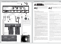
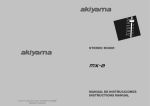
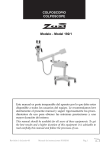
4 channel stereo mixer with DSP effects
INSTRUCTIONS MANUAL
MANUAL DE INSTRUCCIONES
C/ Praga, nº 11. Pol. Cova Solera. 08191. Rubi (Barcelona). Tel: 00 34 935861730 Fax: 00 34 936996087.
E-mail: [email protected] / www.akiyamadj.com
CONNECTIONS / CONEXIONES
WARNINGS / AVISOS
XLR connector for Mic at
front panel
CAUTION
Conector XLR para Micrófono
en panel frontal
RISK OF ELECTRIC SHOCK
DO NOT OPEN
Jack connector for MIC
Conector Jack para
Micrófono
h
h
Channel 1 can act as DJ Mic channel or as normal
POWER AMPLIFIER/ETAPA DE POTENCIA
h
h
h
h
h
h
h
h
h
Up to 7 line level devices can
be connected
Podemos conectar hasta 7
aparatos de nivel de señal de
linea
Up to 3 turntables can be
connected
Podemos conectar hasta 3
giradiscos
Esta señal indica la presencia de componentes del equipo que precisan de
mantenimiento. Para más información sobre éstos lea el manual.
A continuación le consignamos las instrucciones del equipo. Gracias por haber
elegido un productoAkiyama.
h
To secondary amplifier
A amplificador secundario
Esta señal indica la presencia de lugares donde habiendo un elevado
voltaje no presentan aislamiento y por tanto constituye un claro riesgo de
electrocución.
h
h
h
h
stereo Line level channel. On front panel there is a
switch to select mode between Mic and Line. We
have two possible ways to connect Microphone,
via canon connector in front panel or via Jack
connector in back panel.
El canal 1 puede funcionar como canal de
micrófono o como canal estéreo (Línea). Mediante
el conmutador adjunto al canal podemos escoger el
modo de funcionamiento. Podemos conectar el
micrófono o en el panel frontal con un conector
canon o en el panel trasero con un conector Jack.
The exclamation point within an equilateral triangle is intended to alert user
to the presence of important operating and maintenance instructions in the
literature accompanying the appliance.
Estimado Cliente:
channel 1
To Recorder system
A sist. grabador
This lightning flash arrowhead is intended to alert use the presence of
uninsulated “dangerous voltage” within the product´s enclosure that may
be of sufficient magnitude to constitute a risk of electric shock to humans.
Before Use / Security Advice
h
Earth contact for Turntable
Toma de tierra para
giradiscos
CAUTION, RISK OF ELECTRIC SHOCK, DO NOT OPEN.
ATENTION: TO REDUCE RISK OF ELECTRIC SHOCK DO NOT OPERATE INSIDE THE EQUIPMENT.
FOR MAINTENANCE CONTACTYOUR DEALER OR QUALIFIED PERSONNEL.
ATENCION: PARAREDUCIR EL RIESGO DE ELECTROCUCION, NO MANIPULE EL INTERIOR DEL EQUIPO.
PARA REALIZAR EL MANTENIMIENTO DEL EQUIPO PONGASE EN CONTACTO CON EL PERSONAL
QUALIFICADO
h
h
Read this manual completely before using the product.
Keep this manual in your records for future reference.
Follow all instructions printed in this manual, otherwise warranty may be
void.
To pull the AC cord out of the wall outlet, never pull the cable itself, but only
theAC plug.
Pull the AC plug out of the wall outlet before any kind of cleaning of this
product. Use smooth and dry cloth only for cleaning. Check all connection
cables before switching the unit again.
Never use any accessories or modifications not authorised by the
manufacturer of this unit. This can affect the security of the product and the
manufacturer will not take any responsibility in this case.
Avoid any use near open water or high humidity to prevent the risk of electric
shock or fire. Take also care of not placing the unit near sources of heat (e.g.
powerful amplifiers).
Choose a location for operation where the unit is protected from vibration
and where a fixed ground is provided. The manufacturer will not take any
responsibility in case of damage caused by the product having fallen of the
operation ground.
Take care of enough distance between this product and sources of hum and
noise like electric motors and transformers.
Carry this product with great care. Punches, big forces and heavy vibration
may damage this product mechanically.
Take always care of sufficient air convection in this product´s enviroment to
avoid overheating, specially when mounting in a rack or in a case.
Before plugging the AC cord on the wall outlet check whether the AC mains
voltage and frequency is the same as this product is specified for. Whenever
your AC plug should not match the wall outlet contact your dealer
immediately.
Choose the position of theAC cord according to the lowest risk of damage by
foot steps or by squeezing it. Take especial care of the AC cord outlet on the
unit as well as theAC plug and wall outlet an the other end of the cable.
Pull the AC plug out of the wall outlet during thunder-storm in order to avoid
any damage on the unit due toAC voltage peaks.
Check the total maximum power of the AC wall outlet if you connect several
units to one wall outlet, and avoid to overload the wall outlet because this
may bring fire.
If fluids have spilled into the unit or small parts have intruded the unit,
immediately switch off the unit and hand it over to servicing.
Do not open the unit for service purpose, as there are no user serviceable
parts inside. Consequently the manufacturer will not take any responsibility
for damage or personal injury following unauthorised service by the user. In
addition, warranty will be void in any case of unauthorised service by the
user or other non authorised persons.
In cause of not correct function of this unit or damaged AC cord or other
damaged parts, pull immediately the AC plug out of the wall outlet and hand
it over the authorised service for security check.
To meet all aspects of functionality and security during maintenance work to
be performed on this unit, all parts should be replaced by genuine spares.
Consequently, take care of your dealer or maintenance company to be
authorised by the manufacturer.
Antes de utilizar el equipo lea detenidamente las siguientes instrucciones:
h
h
h
h
h
h
h
h
h
h
h
h
h
h
h
h
h
h
h
Lea detenidamente el manual antes de utilizar su equipo.
Mantenga el manual a su disposición para su uso en el futuro.
Siga las instrucciones consignadas en el manual, un uso indebido del equipo
podría dejar sin efecto la garantía.
Para desconectar la clavija de toma de corriente AC, nunca estire del cable.
Hágalo estirando la clavija.
Desconecte el equipo antes de realizar alguna operación de limpieza al
aparato. Utilice un trapo suave y seco para limpiar. Asegúrese de que los
cables están correctamente conectados antes de volver a poner en
funcionamiento el equipo.
Nunca utilice accesorios o realice modificaciones no autorizadas por el
fabricante. Ello puede afectar a la integridad del equipo y el fabricante queda
exonerado de responsabilidad alguna en este caso.
No utilice el equipo cerca del agua o en lugares muy húmedos para evitar
riesgos de descarga eléctrica o fuego. Además evite colocar el equipo cerca de
fuentes de calor (Ej. amplificadores).
Sitúe el equipo en lugares exentos de vibraciones y donde una correcta
sujeción al piso sea posible. El fabricante queda libre de toda responsabilidad
en caso de caída del aparato.
Sitúe el equipo a suficiente distancia de fuentes de ruido eléctrico provocado
por motores eléctricos o transformadores.
Transporte el equipo con cuidado. Los golpes podrían dañarlo.
Tenga siempre presente que colocar el aparato en un lugar sin ventilación
puede producir un sobre calentamiento del mismo.
Antes de conectar el equipo a la red asegúrese de que se trata del voltaje y
frecuencia adecuado. En caso contrario absténgase de conectar el aparato y
póngase en contacto con su distribuidor.
Elija una posición para el cable de conexión a red de forma que esté guarecido
de pisotones y otras agresiones. Especial atención a los extremos del cable de
conexión, es decir las clavijas de conexión a red y a la toma del propio aparato
Durante una tormenta desconecte el equipo de la red. Posibles descargas
eléctricas dañarían el aparato.
En caso de conectar varios equipos a la misma toma de la red verifique que se
dispone de la suficiente potencia. En caso de que la potencia no fuera la
suficiente se produciría una sobrecarga y se podría dañar los equipos
En caso de que algún fluido o pequeñas partículas sólidas sean derramadas
sobre el aparato y se introduzcan en éste, apáguelo y llévelo al servicio técnico
para su verificación.
No manipule el equipo con fines a su manutención pues éste no dispone de
piezas que lo precisen. En caso de que se manipule el interior del equipo la
empresa queda exonerada de cualquier responsabilidad para con el equipo y
la persona que lo manipula.Además la garantía pierde su vigencia.
En caso de que el aparato no funcione correctamente por cualquier razón
imputable al equipo, desconéctelo de la red y llévelo a un distribuidor
autorizado para su revisión.
Durante cualquier manipulación del equipo, para mantener todas las
cualidades del mismo tanto en prestaciones como en seguridad para el usuario
es necesario utilizar sólo recambios originales. Asegúrese de que la empresa
que realice el mantenimiento esté autorizada por el fabricante o distribuidor.
Health advise
Aviso que atañe a su salud
This unit produces and absorbs electromagnetic radiation. The strength of
radiation and the sensitivity for disturbing interference meet the CE
requirements. A corresponding is printed on the backside of the unit. Any
change or modification may affect the behaviour of the unit concerning
electromagnetic radiation, with the CE requirements eventually not to be meet
anymore.
Este equipo produce y absorbe radiación electromagnética. La intensidad y la
sensibilidad a distorsiones del exterior cumplen los criterios especificados por la
C.E. En la parte posterior del equipo aparece un signo indicando la adecuación a
las normas C.E. En caso de realizarse alguna manipulación no autorizada sobre
el equipo podría alterarse las características del campo magnético producido
por el equipo. En dicho caso el fabricante/distribuidor queda exento de toda
responsabilidad.
CD PLAYER/REPRODUCTOR DE CD
8
mcx
TURNTABLE/GIRADISCOS
mcx
1
FUNCTIONS
Front Panel
FUNCIONES
9
1
Panel trasero
1
3
english
8
2
11
1
4
5
10
2
3
4
11
12
21
22
5
23
10
6
8
9
7
24
6
25
26
27
13
7
28
17
14
18
29
15
30
19
7.- Salida Master Balanceada - Conector XLR3 o Canon. Este tipo
de conexión es usada para conectar el mezclador a una etapa de
potencia profesional. Es especialmente útil cuando el cable de
conexión es largo, dado que en estas condiciones incorpora ruidos
que el circuito de balanceo anula.
8.- Salida Booth L,R - Se trata de un segundo Master dedicado a la
cabina del Disk Jockey (es necesario otro amplificador)
9.- REC (grabación) L,R - Se utiliza para grabar las sesiones. Es
independiente del control Master, incluso con Master al mínimo
seguimos registrando la sesión.
10.- Conexión a redAC - Conecte a la red de suministro eléctrico.
Atención: Asegurese siempre de que la tensión y frecuencia de la red
coinciden con los indicados en el mezclador.
11.- Conexión a tierra - Los giradiscos disponen de un cable auxiliar
de masa o tierra. Conecte este cable a la toma de tierra del mezclador,
de este modo anulamos los posibles ruidos de masa o tierra (hum).
SEÑALES DE ENTRADA
1.- Entradas Phono L,R - Inserte aquí los conectores RCA de los
giradiscos tipo (MM, moving magnet).
2.- Entradas de nivel de linea L,R -Inserte aquí los conectores RCA
de cualquier fuente de señal de linea (CD Player, MD player, Cassette
Player etc.)
3.- Igual al punto (2)
4.- Entrada auxiliar de Micrófono (Jack 6.3) - El micrófono
dispone de dos entradas, una Canon en el panel frontal y una Jack 6.3
en el panel trasero.
5.- Entradas de nivel de linea L,R - Igual al punto (2)
SEÑALES DE SALIDA
6.- Salida Master L,R (RCA) - Conecte al amplificador.
Normalmente usamos esta salida para conectar a amplificadores
domésticos o amplificadores que no necesitan cables largos.
16
20
Booth controls. Furthermore, the level of the channels can depend
on the setting of the Crossfader if these channels are assigned to it by
means of the Crossfader assign control. To be in-field replaceable,
this part is front-detachable. For replacement, switch off the unit
and unscrew the 2 outer screws of the crossfader and remove the
part; detach the connector and replace the part. Plug in the connector
and screw the new part to the main body again.
7.-Crossfader selector: By means of this control we can send the
channel signal to:
-A:Crossfader Left and Left bank of Kill effect
-B: Crossfader Right and Right bank of Kill effect
-Bypass: Send channel signal strait to Master Bus
8.-Microphone connector
THE CHANNEL
1.-Input assign switches: These switches allow to choose which of
the following backpanel inputs will be audible:
Phono (turntable MM cartridge) or CD or Line (CD and Line inputs
are same characteristics)
2.-Gain Control: Allows the adjustment of the channel input
sensitivity regarding the different source levels. Each channel has
an optical check up by means of the 10 LED bargraphs of the level
meter.
3.-Channel EQ: Independent control is provided for the high
(13KHz), the mid (1KHz) and the low (70Hz) frequency band.
Please be aware, that any boosted frequency band will increase the
total level and decrease the level headroom.
4.-Channel level meter: The meter display the channel level before
channel fader. To set the channel at the right level, when in play
back, set the Gain in a way that all green Leds light and the yellow
and red only blink.
5.-Headphones assign switch (Cue): With these switches you can
assign any of the input channels to be replayed on the headphones.
Please note that you can only hear the required source if the input
assign switch is switched to the respective position and the source is
in play mode.
6.-Channel fader: By means of these controls, you determine the
part of the overall level, that a specific channel contributes. Please
be aware of the final output level to be adjusted by the Master and
2
MASTER SECTION (and Crossfader)
Conectores
RCA
Jack 6.3 mono
Entradas y salidas de Linea y Phono
Micrófono panel trasero
XLR3 o Canon
Jack 6.3 stereo
Salida Master Balanceada
Auriculares
9.-Power switch: With the AC plug plugged into the wall outlet, the
unit may be switched on by means of this switch; a second press of
the switch will switch the unit off again. Once the mixer is switched
on the FX Section displays will light up.Attention: Always take
care of switching on your mixer first and your amplifier at last to
avoid switching noise damaging your speakers; for switching off,
switch off your amplifier first and your mixer at last.
Shield:sleve
Hot: tip
Cold: ring
mcx
mcx
7
FUNCIONES
FUNCTIONS
20.- Conector para auriculares: Jack 6.3 estereo. Conecte aqui
sus auriculares
10.- Nivel de Señal de salida: Se dispone de dos picómetros.
Miden el nivel de señal en un rango de -20 a +9 dB. Existen dos
modos de monitorización:
SECCIÓN DE EFECTOS. DSP
21.- Analizador de Beat (BPM) para señal Master: El
sofisticado analizador de BPM ofrece una lectura del valor en el
display.
22.- Display de parámetros (parámetro/bpm): El valor
representado en el display dependerá del estado del selector de
efectos de canal (27) y del canal seleccionado para envio a
efectos (28). Al actuar sobre este control nos proporcionará el
valor BPM del canal seleccionado. El display parpadeará en caso
de no poder analizar el Beat.
23.- Beat (Effect Synchronous Display/Beat Display): La
medida indicada dependerá de la posición del Selector de
Efectos (27).
1) Si hemos seleccionado DELAY/ECHO/PAN/TRANS: el
parámetro del efecto se representa en forma de Beat. Si el valor
del parámetro del efecto es 1/2, 3/4, 1/1, 2/1 ó 4/1 se iluminará el
LED correspondiente. Presionando el control Beat (24)
cambiamos el valor del parámetro. En caso de que exista una
disparidad en el número de Beats el LED correspondiente al valor
más próximo parpadeará.
2) Si hemos seleccionado FILTER/FLANGER: el parámetro del
efecto se representa en forma de Beat. Si el valor del parámetro
del efecto es 1/2, 3/4, 1/1, 2/1 o 4/1 se iluminará el LED
correspondiente. Presionando el control Beat (24) cambiamos el
valor del parámetro. En caso de que exista una disparidad en el
número de Beats el LED correspondiente al valor más próximo
parpadeará.
3) Si hemos seleccionado PITCH: se indica el porcentaje de Ptich
seleccionado.
24.- Selector de beat de efectos: Varia el valor del parámetro de
efectos, display (25), ajustándolo a múltiplos del valor de BPM
del canal seleccionado mediante el control (28). La naturaleza de
el parámetro dependerá del efecto seleccionado mediante (27).
1) Si hemos seleccionado DELAY/ECHO/PAN/TRANS: el
parámetro del efecto se representa en forma de Beat. Presionando
el control Beat (24) podremos escoger entre los siguientes
múltiplos del valor de BPM 1/2, 3/4, 1/1,2/1 o 4/1.
2) Si hemos seleccionado FILTER/FLANGER: el parámetro del
efecto se representa en forma de Beat. Presionando el control Beat
(24) podremos escoger entre los siguientes múltiplos del valor de
BPM 1/2, 3/4, 1/1,2/1 o 4/1.
3) Si hemos seleccionado PITCH: se indica el porcentaje de Pitch
seleccionado. Presionando el control Beat (24) podremos escoger
entre los siguientes valores porcentuales de Pitch -100%, -50%,
0%, 50% y 100%.
25.- Control de parámetros: Es utilizado para ajustar el valor de
los parámetros del efecto seleccionado.
26.- Control de cantidad de efecto: Nos permite graduar el
porcentaje de señal aplicada a efectos versus señal original.
27.- Selector de efecto: Nos permite seleccionar el efecto a
aplicar a la señal seleccionada.
28.- Selector de canal a efectos: Mediante este control
escogemos el canal que sera afectado por la DSP de efectos.
29.- Preescucha de efectos: Nos permite realizar una
pre/escucha de los efectos aplicados.
30.- Botón on/off de efectos: Activa el efecto escogido al canal
seleccionado.
I-Selector Stereo/Split en posición STEREO: escuchamos una
mezcla estéreo de ambas señales.
II-Selector Stereo/Split en posición SPLIT: en el auricular
izquierdo escuchamos la señal entrante y en el auricular derecho
la señal Master (ambas en mono). Girando el control graduamos
el nivel de ambas señales.
16.- Control de volumen de auriculares. Le permite controlar
el volumen en un auricular estéreo conectado al mezclador. Por
favor, asegúrese de que la impedancia del auricular sea como
mínimo de 32 Ohmios. Además, esté prevenido contra
auriculares de elevada impedancia que reducirán el nivel
máximo de salida en auricular. Se recomienda escoger un
auricular con una impedancia no superior a 200 Ohmios.
Atención, se recomienda mantener el volumen al mínimo antes
de comenzar la reproducción.
17.- Boost: Incrementa en 6 dB el nivel de las frecuencias bajas
de la señal (100Hz). Utilízalo en sincronía con el Beat.
18.- Crossfader: Dada la condición de los Fader de los canales
que estén dirigidos al Crossfader estén “abiertos”, se podrá
combinar la señal de éstos (acción de Crossfader o fundido).
Para mayor operatividad y agilidad del equipo, el componente
mecánico donde se localiza la función de Crossfader es
reemplazable. Para reemplazar el Crossfader desaloje los
tornillos exteriores y retire la pieza; desconecte el conector y
cambie la pieza. De la nueva pieza conecte el conector y
atornille la nueva pieza al equipo.
19.- Reverse: Invierte las entradas izquierda y derecha a
Crossfader. Estando en modo Reverse un Led se iluminará.
6
mcx
DSPEFFECTS SECTION
21.- Master Automatic bpm (beat per minute) counter
display - This sophisticated counter automatically calculates the
BPM of the signal at Master.
22.-Automatic (parameter/BPM Counter) info display - This
sophisticated counter automatically calculates the BPM of any
audio source selected by means of the control Source switch
(28). Moreover, the display will differ with the setting of the
effect channel selector switch (27). The BPM for the source
selected with the effect channel selector knob (27) will be
displayed. Display will flash while BPM is being measured or
cannot be measured.
23.- Beat (Effect Synchronous Display/Beat Display) - The
display will differ with the setting of the effect selector switch
(27).
1. If DELAY, ECHO, PAN or TRANS has been selected,
parameter for source BPM will be displayed in terms of a beat. It
will light if the beat is from 1/2 to 4/1. Pressing the effect beat
sync. button (24) will change beats clearing the display entirely. If
there is a disparity between the number of beats, the closest
number will be displayed blinking.
2. If FILTER, FLANGER has been selected, parameter for source
BPM will be displayed in terms of a beat. Pressing the effect beat
sync. button (24) will change the beat clearing the display
entirely. If there is a disparity between the number of beats, the
closest number will be displayed blinking.
3. If PITCH has been selected, the extent of pitch adjustment will
be display.
24.- Effect beat sync. - The value for effect parameter (25) will
change in keeping with the BPM for source selected with the
effect source selector switch (28). The set value will change with
the effect selector switch (27) setting.
1. If DELAY, ECHO, PAN or TRANS has been selected,
parameter for source BPM will be set in terms of a beat (1/2 to
4/1).
2. IF FILTER, FLANGER has been selected, parameter for
source BPM will be set in terms of a number of beats (1/2 to 4/1).
3. IF DELAY or ECHO has been selected, the number of beats for
parameter cannot be set in excess of 2000 ms.
4. IF PITCH has been selected, settings of -100%, -50%,
0%, 50% and 100% will be possible.
25.- Parameter knob - Used to adjust the value of the parameters
of the built-in effector.
26.- Effects Depth Control - Used to adjust the amount of
effected music versus de amount of uneffected music.
27.- Effects selector switch - Used to select the effect to add to
the music.
28.- Source Channel Selector switch - Used to select the source
to be effected.
29.- Effects Cue - With these switch you replay on the
headphones the effected music.
30.- Effect on/off button - Engages the effect selected to the
selected source.
mcx
english
I-Selector Stereo/Split en posición STEREO: mide el nivel de la
señal MASTER. Cada Picómetro mide la señal de un canal
(izquierdo y derecho respectivamente). Nos permite controlar la
señal de salida de modo que no exista distorsión durante el
proceso de mezcla.
II-Selector Stereo/Split en posición SPLIT: El picómetro de la
izquierda medirá el nivel de la señal de la fuente asignada a CUE y
el picómetro de la derecha medirá el nivel de la señal del BUS
MASTER en modo Mono. De este modo podremos comparar
ambas señales.
11.- Control de nivel Booth: Controla independientemente de
Master un amplificador externo. Advierta que la señal no se
muestra en el medidor de nivel de señal de salida;
consecuentemente, sea prudente y no sobrecargue su
amplificador.
12.- Control de nivel Master & Balance: Controla
independientemente del Booth un amplificador externo (el
principal). Esta señal se muestra en el medidor de nivel de señal
de salida. Mediante el control Balance Master podemos enviar la
señal al canal izquierdo o derecho de las dos pistas estéreo.
13.- Selector Mono/Stereo: Podemos transformar la señal de
salida, normalmente estéreo, en mono.
14.- Conmutador Stereo/Split para auriculares: En
posición estéreo le permitirá escuchar la señal preseleccionada
mediante CUE en estéreo. En posición Split escuchará en un
auricular la señal preseleccionada mediante CUE y en el otro la
señal Master (ambas en mono).
15.- Control panorámico de CUE: Mediante esta función
podrá escuchar una mezcla entre las señales entrantes (señal
preseleccionada CUE) y la señal de salida Master (pre pot).
10.-Level meter: The level meter shows the stereo output level
of Master output when CUE selector in Stereo mode. When CUE
selector in Split mode the left bargraph will show CUE level and
the right bargraph will depict Master level.
11.-Booth level control: Controls independently from Master
an external amplifier. Please note that the level of this output will
not in any case be displayed on the level meter; consequently,
please check carefully for your amplifier not being overloaded.
12.-Master level control & Balance: Controls independently
from Booth an external amplifier (main amplifier). The signal's
stereo balance can be controlled by means of control Balance
Master. This signal is displayed on the level meter.
13.-Mono/Stereo Selector: We can transform output signal,
normally stereo, in mono.
14.-Stereo/split-switch for headphones: Position "stereo" will
make you hear the preselected signal by means of CUE controls
in stereo, while position "split" will make you hear the CUE
preselected signal on one earcup and the Master output signal on
the other earcup.
15.-Cue Pan: By means of this function, you can preview your
forthcoming mix by crossfading between the preselected
headphones signal on the left side of the control and the Master
output signal (pre pot) on the right side of the control.
16.-Headphones level control: With a stereo headphone
connected, you may control the headphones volume. Please
check your headphones impedance for a minimum of 32 Ohms
and be aware of high-impedance headphones reducing the
maximum output power of this output, so that you should choose
a headphone with less than 200 Ohms of impedance.
17.-Boost: Increases 6 dB the level of low level frequencies
(100Hz). Use it to enhance the Beat.
18.-Crossfader: Under the precondition of opened channel
faders of those channels being routed to the crossfader, you can
crossfade between these two input channels. To be in-field
replaceable, this part is front-detachable. For replacement,
switch off the unit and unscrew the 2 outer screws of the
crossfader and remove the part; detach the connector and replace
the part. Plug in the connector and screw the new part to the main
body again.
19.-Reverse: Reverses the inputs right and left to the crossfader.
When in reverse mode a Led will light.
20.-Headphones connector: Jack 6.3 stereo. Connect here the
headphones.
3
FUNCTIONS
FUNCIONES
Panel frontal
Rear Panel
9
1
1
3
2
11
1
4
5
8
10
english
2
3
4
11
12
21
22
5
10
6
8
9
23
7
24
6
professional use. Specially when cable lines are long and therefore
can caught unwanted noise.
8.- Booth output L,R - This is a second Master output normally used
for monitoring at the DJ cabin (when avaialble).
9.- REC L,R - The record output is not affected by the Master
volume control. It can be used to record even while the master volume
is off.
10.- AC Input - Input connection for the inboard power supply.
Connect it to the wall outlet socket.
Always assure that the tension and frequency of the outlet matched
the specified at the mixer.
11.- Ground connector - Connects to the turntable ground connector
to eliminate electrical hum. Ground connectors are usually supplied
with turntables.
INPUTS
1.- Phono inputs L,R - Insert here connectors from turntables (MM)
type
2.- Cd level inputs L,R - Insert here connectors from any line level
signal device. That is CD Player, MD player, Cassette Player etc.
3.- Line level inputs L,R - Same as point (2)
4.- Mic input (Jack 6.3) - Microphone has the input connector
duplicated. You have one at the front panel and another at rear panel.
That is a Jack 6.3.
5.- Line level inputs L,R - Same as point (2)
OUTPUTS
6.- Master output L,R (RCA) - Connect to the amplfier system.
Normally RCA output are used at domestic setups or cable lines are
short.
7.- Balanced Master output - Balanced XLR3 or Cannon
connectors are typically used to connect to the amplfier system for
25
26
27
13
7
28
17
14
18
29
15
30
19
16
20
6.- Fader de canal: Mediante estos controles, usted determina la parte
del nivel global al que un canal específico contribuye. Por favor advierta
que el nivel final de salida debe ser ajustado mediante el Master y el
Booth. Además el nivel de los canales puede depender del Crossfader en
caso de que el canal sea direccionado al Crossfader por medio del
control de asignación a Crossfader (a/b/bypass).
7.-Selector de Crossfader & Kill: Nos permite enviar la señal del
canal a:
-A: Crossfader Izquierdo y módulo izquierdo de Kill
-B: Crossfader Derecho y módulo Derecho de Kill
-Bypass: Envía la señal del canal directamente al Master Bus
8.- Conector XLR (Canon) para micrófono
EL CANAL
Connectors
RCA
Jack 6.3 mono
Line and Phono inputs
Several outputs
Rear panel Microphon
XLR3 o Canon
Jack 6.3 stereo
Master Balanced output
Headphones
Shield:sleve
Hot: tip
Cold: ring
4
mcx
1.- Conmutadores de asignación de entradas: Mediante la palanca de
cada canal decidimos que fuente reproductora está activa de las tres
posibles conectadas a cada canal.
Se dispone de tres posibles selecciones:
Phono (giradiscos con cápsula MM)
CD, Linea (CD y Línea son el mismo tipo de entrada)
2.- Control de ganancia: Permite el ajuste de la sensibilidad del canal
de entrada en función de las distintas fuentes. Para cada canal es
posible realizar un ajuste óptico mediante la barra de LED o picómetro .
3.-Ecualizador de Canal : Se dispone de un control independiente para
frecuencias altas (13KHz), medidas (1KHz) y bajas (70Hz). Por favor
advierta que cualquier banda de frecuencia sobre elevada incrementará
el nivel total y hará decrecer el rango dinámico del equipo. Además,
puede elevar el nivel global de la señal hasta llegar a la saturación.
4.- Medidor de nivel de canal: Nos indica el nivel de la señal en el canal
justo antes de la atenuación del fader. Para regular la sensibilidad de
entrada actúe sobre el control Gain de modo que las luces verdes del
medidor estén encendidas y las luces naranja y rojas sólo se
enciendan ocasionalmente.
5.- Conmutador de asignación de auriculares (CUE): Mediante estos
conmutadores usted puede asignar cualquiera de los canales de entrada
para ser reproducidos a través de los auriculares. Por favor advierta que
sólo podrá escuchar la fuente deseada si el conmutador de asignación de
entradas está conectado en su posición correspondiente y el equipo
fuente está reproduciendo. Atención, se recomienda mantener el
volumen al mínimo antes de comenzar la reproducción.
SECCIÓN MASTER (y Crossfader)
9.- Interruptor puesta en marcha: Conectar el dispositivo de
conexión a red AC a la toma de la pared. Accionando el conmutador
power switch el aparato será puesto en marcha. Mediante una segunda
acción sobre el conmutador el aparato se apagará. Al presionar el botón
ON los displays se iluminarán.
Atención: Tenga siempre la precaución de enchufar primero el
mezclador y a continuación el amplificador para evitar que el ruido de
conexión dañe sus altavoces; para apagar el equipo, apague primero el
amplificador y a continuación el mezclador.
mcx
5
FUNCIONES
FUNCTIONS
20.- Conector para auriculares: Jack 6.3 estereo. Conecte aqui
sus auriculares
10.- Nivel de Señal de salida: Se dispone de dos picómetros.
Miden el nivel de señal en un rango de -20 a +9 dB. Existen dos
modos de monitorización:
SECCIÓN DE EFECTOS. DSP
21.- Analizador de Beat (BPM) para señal Master: El
sofisticado analizador de BPM ofrece una lectura del valor en el
display.
22.- Display de parámetros (parámetro/bpm): El valor
representado en el display dependerá del estado del selector de
efectos de canal (27) y del canal seleccionado para envio a
efectos (28). Al actuar sobre este control nos proporcionará el
valor BPM del canal seleccionado. El display parpadeará en caso
de no poder analizar el Beat.
23.- Beat (Effect Synchronous Display/Beat Display): La
medida indicada dependerá de la posición del Selector de
Efectos (27).
1) Si hemos seleccionado DELAY/ECHO/PAN/TRANS: el
parámetro del efecto se representa en forma de Beat. Si el valor
del parámetro del efecto es 1/2, 3/4, 1/1, 2/1 ó 4/1 se iluminará el
LED correspondiente. Presionando el control Beat (24)
cambiamos el valor del parámetro. En caso de que exista una
disparidad en el número de Beats el LED correspondiente al valor
más próximo parpadeará.
2) Si hemos seleccionado FILTER/FLANGER: el parámetro del
efecto se representa en forma de Beat. Si el valor del parámetro
del efecto es 1/2, 3/4, 1/1, 2/1 o 4/1 se iluminará el LED
correspondiente. Presionando el control Beat (24) cambiamos el
valor del parámetro. En caso de que exista una disparidad en el
número de Beats el LED correspondiente al valor más próximo
parpadeará.
3) Si hemos seleccionado PITCH: se indica el porcentaje de Ptich
seleccionado.
24.- Selector de beat de efectos: Varia el valor del parámetro de
efectos, display (25), ajustándolo a múltiplos del valor de BPM
del canal seleccionado mediante el control (28). La naturaleza de
el parámetro dependerá del efecto seleccionado mediante (27).
1) Si hemos seleccionado DELAY/ECHO/PAN/TRANS: el
parámetro del efecto se representa en forma de Beat. Presionando
el control Beat (24) podremos escoger entre los siguientes
múltiplos del valor de BPM 1/2, 3/4, 1/1,2/1 o 4/1.
2) Si hemos seleccionado FILTER/FLANGER: el parámetro del
efecto se representa en forma de Beat. Presionando el control Beat
(24) podremos escoger entre los siguientes múltiplos del valor de
BPM 1/2, 3/4, 1/1,2/1 o 4/1.
3) Si hemos seleccionado PITCH: se indica el porcentaje de Pitch
seleccionado. Presionando el control Beat (24) podremos escoger
entre los siguientes valores porcentuales de Pitch -100%, -50%,
0%, 50% y 100%.
25.- Control de parámetros: Es utilizado para ajustar el valor de
los parámetros del efecto seleccionado.
26.- Control de cantidad de efecto: Nos permite graduar el
porcentaje de señal aplicada a efectos versus señal original.
27.- Selector de efecto: Nos permite seleccionar el efecto a
aplicar a la señal seleccionada.
28.- Selector de canal a efectos: Mediante este control
escogemos el canal que sera afectado por la DSP de efectos.
29.- Preescucha de efectos: Nos permite realizar una
pre/escucha de los efectos aplicados.
30.- Botón on/off de efectos: Activa el efecto escogido al canal
seleccionado.
I-Selector Stereo/Split en posición STEREO: escuchamos una
mezcla estéreo de ambas señales.
II-Selector Stereo/Split en posición SPLIT: en el auricular
izquierdo escuchamos la señal entrante y en el auricular derecho
la señal Master (ambas en mono). Girando el control graduamos
el nivel de ambas señales.
16.- Control de volumen de auriculares. Le permite controlar
el volumen en un auricular estéreo conectado al mezclador. Por
favor, asegúrese de que la impedancia del auricular sea como
mínimo de 32 Ohmios. Además, esté prevenido contra
auriculares de elevada impedancia que reducirán el nivel
máximo de salida en auricular. Se recomienda escoger un
auricular con una impedancia no superior a 200 Ohmios.
Atención, se recomienda mantener el volumen al mínimo antes
de comenzar la reproducción.
17.- Boost: Incrementa en 6 dB el nivel de las frecuencias bajas
de la señal (100Hz). Utilízalo en sincronía con el Beat.
18.- Crossfader: Dada la condición de los Fader de los canales
que estén dirigidos al Crossfader estén “abiertos”, se podrá
combinar la señal de éstos (acción de Crossfader o fundido).
Para mayor operatividad y agilidad del equipo, el componente
mecánico donde se localiza la función de Crossfader es
reemplazable. Para reemplazar el Crossfader desaloje los
tornillos exteriores y retire la pieza; desconecte el conector y
cambie la pieza. De la nueva pieza conecte el conector y
atornille la nueva pieza al equipo.
19.- Reverse: Invierte las entradas izquierda y derecha a
Crossfader. Estando en modo Reverse un Led se iluminará.
6
mcx
DSPEFFECTS SECTION
21.- Master Automatic bpm (beat per minute) counter
display - This sophisticated counter automatically calculates the
BPM of the signal at Master.
22.-Automatic (parameter/BPM Counter) info display - This
sophisticated counter automatically calculates the BPM of any
audio source selected by means of the control Source switch
(28). Moreover, the display will differ with the setting of the
effect channel selector switch (27). The BPM for the source
selected with the effect channel selector knob (27) will be
displayed. Display will flash while BPM is being measured or
cannot be measured.
23.- Beat (Effect Synchronous Display/Beat Display) - The
display will differ with the setting of the effect selector switch
(27).
1. If DELAY, ECHO, PAN or TRANS has been selected,
parameter for source BPM will be displayed in terms of a beat. It
will light if the beat is from 1/2 to 4/1. Pressing the effect beat
sync. button (24) will change beats clearing the display entirely. If
there is a disparity between the number of beats, the closest
number will be displayed blinking.
2. If FILTER, FLANGER has been selected, parameter for source
BPM will be displayed in terms of a beat. Pressing the effect beat
sync. button (24) will change the beat clearing the display
entirely. If there is a disparity between the number of beats, the
closest number will be displayed blinking.
3. If PITCH has been selected, the extent of pitch adjustment will
be display.
24.- Effect beat sync. - The value for effect parameter (25) will
change in keeping with the BPM for source selected with the
effect source selector switch (28). The set value will change with
the effect selector switch (27) setting.
1. If DELAY, ECHO, PAN or TRANS has been selected,
parameter for source BPM will be set in terms of a beat (1/2 to
4/1).
2. IF FILTER, FLANGER has been selected, parameter for
source BPM will be set in terms of a number of beats (1/2 to 4/1).
3. IF DELAY or ECHO has been selected, the number of beats for
parameter cannot be set in excess of 2000 ms.
4. IF PITCH has been selected, settings of -100%, -50%,
0%, 50% and 100% will be possible.
25.- Parameter knob - Used to adjust the value of the parameters
of the built-in effector.
26.- Effects Depth Control - Used to adjust the amount of
effected music versus de amount of uneffected music.
27.- Effects selector switch - Used to select the effect to add to
the music.
28.- Source Channel Selector switch - Used to select the source
to be effected.
29.- Effects Cue - With these switch you replay on the
headphones the effected music.
30.- Effect on/off button - Engages the effect selected to the
selected source.
mcx
english
I-Selector Stereo/Split en posición STEREO: mide el nivel de la
señal MASTER. Cada Picómetro mide la señal de un canal
(izquierdo y derecho respectivamente). Nos permite controlar la
señal de salida de modo que no exista distorsión durante el
proceso de mezcla.
II-Selector Stereo/Split en posición SPLIT: El picómetro de la
izquierda medirá el nivel de la señal de la fuente asignada a CUE y
el picómetro de la derecha medirá el nivel de la señal del BUS
MASTER en modo Mono. De este modo podremos comparar
ambas señales.
11.- Control de nivel Booth: Controla independientemente de
Master un amplificador externo. Advierta que la señal no se
muestra en el medidor de nivel de señal de salida;
consecuentemente, sea prudente y no sobrecargue su
amplificador.
12.- Control de nivel Master & Balance: Controla
independientemente del Booth un amplificador externo (el
principal). Esta señal se muestra en el medidor de nivel de señal
de salida. Mediante el control Balance Master podemos enviar la
señal al canal izquierdo o derecho de las dos pistas estéreo.
13.- Selector Mono/Stereo: Podemos transformar la señal de
salida, normalmente estéreo, en mono.
14.- Conmutador Stereo/Split para auriculares: En
posición estéreo le permitirá escuchar la señal preseleccionada
mediante CUE en estéreo. En posición Split escuchará en un
auricular la señal preseleccionada mediante CUE y en el otro la
señal Master (ambas en mono).
15.- Control panorámico de CUE: Mediante esta función
podrá escuchar una mezcla entre las señales entrantes (señal
preseleccionada CUE) y la señal de salida Master (pre pot).
10.-Level meter: The level meter shows the stereo output level
of Master output when CUE selector in Stereo mode. When CUE
selector in Split mode the left bargraph will show CUE level and
the right bargraph will depict Master level.
11.-Booth level control: Controls independently from Master
an external amplifier. Please note that the level of this output will
not in any case be displayed on the level meter; consequently,
please check carefully for your amplifier not being overloaded.
12.-Master level control & Balance: Controls independently
from Booth an external amplifier (main amplifier). The signal's
stereo balance can be controlled by means of control Balance
Master. This signal is displayed on the level meter.
13.-Mono/Stereo Selector: We can transform output signal,
normally stereo, in mono.
14.-Stereo/split-switch for headphones: Position "stereo" will
make you hear the preselected signal by means of CUE controls
in stereo, while position "split" will make you hear the CUE
preselected signal on one earcup and the Master output signal on
the other earcup.
15.-Cue Pan: By means of this function, you can preview your
forthcoming mix by crossfading between the preselected
headphones signal on the left side of the control and the Master
output signal (pre pot) on the right side of the control.
16.-Headphones level control: With a stereo headphone
connected, you may control the headphones volume. Please
check your headphones impedance for a minimum of 32 Ohms
and be aware of high-impedance headphones reducing the
maximum output power of this output, so that you should choose
a headphone with less than 200 Ohms of impedance.
17.-Boost: Increases 6 dB the level of low level frequencies
(100Hz). Use it to enhance the Beat.
18.-Crossfader: Under the precondition of opened channel
faders of those channels being routed to the crossfader, you can
crossfade between these two input channels. To be in-field
replaceable, this part is front-detachable. For replacement,
switch off the unit and unscrew the 2 outer screws of the
crossfader and remove the part; detach the connector and replace
the part. Plug in the connector and screw the new part to the main
body again.
19.-Reverse: Reverses the inputs right and left to the crossfader.
When in reverse mode a Led will light.
20.-Headphones connector: Jack 6.3 stereo. Connect here the
headphones.
3
FUNCTIONS
Front Panel
FUNCIONES
9
1
Panel trasero
1
3
english
8
2
11
1
4
5
10
2
3
4
11
12
21
22
5
23
10
6
8
9
7
24
6
25
26
27
13
7
28
17
14
18
29
15
30
19
7.- Salida Master Balanceada - Conector XLR3 o Canon. Este tipo
de conexión es usada para conectar el mezclador a una etapa de
potencia profesional. Es especialmente útil cuando el cable de
conexión es largo, dado que en estas condiciones incorpora ruidos
que el circuito de balanceo anula.
8.- Salida Booth L,R - Se trata de un segundo Master dedicado a la
cabina del Disk Jockey (es necesario otro amplificador)
9.- REC (grabación) L,R - Se utiliza para grabar las sesiones. Es
independiente del control Master, incluso con Master al mínimo
seguimos registrando la sesión.
10.- Conexión a redAC - Conecte a la red de suministro eléctrico.
Atención: Asegurese siempre de que la tensión y frecuencia de la red
coinciden con los indicados en el mezclador.
11.- Conexión a tierra - Los giradiscos disponen de un cable auxiliar
de masa o tierra. Conecte este cable a la toma de tierra del mezclador,
de este modo anulamos los posibles ruidos de masa o tierra (hum).
SEÑALES DE ENTRADA
1.- Entradas Phono L,R - Inserte aquí los conectores RCA de los
giradiscos tipo (MM, moving magnet).
2.- Entradas de nivel de linea L,R -Inserte aquí los conectores RCA
de cualquier fuente de señal de linea (CD Player, MD player, Cassette
Player etc.)
3.- Igual al punto (2)
4.- Entrada auxiliar de Micrófono (Jack 6.3) - El micrófono
dispone de dos entradas, una Canon en el panel frontal y una Jack 6.3
en el panel trasero.
5.- Entradas de nivel de linea L,R - Igual al punto (2)
SEÑALES DE SALIDA
6.- Salida Master L,R (RCA) - Conecte al amplificador.
Normalmente usamos esta salida para conectar a amplificadores
domésticos o amplificadores que no necesitan cables largos.
16
20
Booth controls. Furthermore, the level of the channels can depend
on the setting of the Crossfader if these channels are assigned to it by
means of the Crossfader assign control. To be in-field replaceable,
this part is front-detachable. For replacement, switch off the unit
and unscrew the 2 outer screws of the crossfader and remove the
part; detach the connector and replace the part. Plug in the connector
and screw the new part to the main body again.
7.-Crossfader selector: By means of this control we can send the
channel signal to:
-A:Crossfader Left and Left bank of Kill effect
-B: Crossfader Right and Right bank of Kill effect
-Bypass: Send channel signal strait to Master Bus
8.-Microphone connector
THE CHANNEL
1.-Input assign switches: These switches allow to choose which of
the following backpanel inputs will be audible:
Phono (turntable MM cartridge) or CD or Line (CD and Line inputs
are same characteristics)
2.-Gain Control: Allows the adjustment of the channel input
sensitivity regarding the different source levels. Each channel has
an optical check up by means of the 10 LED bargraphs of the level
meter.
3.-Channel EQ: Independent control is provided for the high
(13KHz), the mid (1KHz) and the low (70Hz) frequency band.
Please be aware, that any boosted frequency band will increase the
total level and decrease the level headroom.
4.-Channel level meter: The meter display the channel level before
channel fader. To set the channel at the right level, when in play
back, set the Gain in a way that all green Leds light and the yellow
and red only blink.
5.-Headphones assign switch (Cue): With these switches you can
assign any of the input channels to be replayed on the headphones.
Please note that you can only hear the required source if the input
assign switch is switched to the respective position and the source is
in play mode.
6.-Channel fader: By means of these controls, you determine the
part of the overall level, that a specific channel contributes. Please
be aware of the final output level to be adjusted by the Master and
2
MASTER SECTION (and Crossfader)
Conectores
RCA
Jack 6.3 mono
Entradas y salidas de Linea y Phono
Micrófono panel trasero
XLR3 o Canon
Jack 6.3 stereo
Salida Master Balanceada
Auriculares
9.-Power switch: With the AC plug plugged into the wall outlet, the
unit may be switched on by means of this switch; a second press of
the switch will switch the unit off again. Once the mixer is switched
on the FX Section displays will light up.Attention: Always take
care of switching on your mixer first and your amplifier at last to
avoid switching noise damaging your speakers; for switching off,
switch off your amplifier first and your mixer at last.
Shield:sleve
Hot: tip
Cold: ring
mcx
mcx
7
CONNECTIONS / CONEXIONES
WARNINGS / AVISOS
XLR connector for Mic at
front panel
CAUTION
Conector XLR para Micrófono
en panel frontal
RISK OF ELECTRIC SHOCK
DO NOT OPEN
Jack connector for MIC
Conector Jack para
Micrófono
h
h
Channel 1 can act as DJ Mic channel or as normal
POWER AMPLIFIER/ETAPA DE POTENCIA
h
h
h
h
h
h
h
h
h
Up to 7 line level devices can
be connected
Podemos conectar hasta 7
aparatos de nivel de señal de
linea
Up to 3 turntables can be
connected
Podemos conectar hasta 3
giradiscos
Esta señal indica la presencia de componentes del equipo que precisan de
mantenimiento. Para más información sobre éstos lea el manual.
A continuación le consignamos las instrucciones del equipo. Gracias por haber
elegido un productoAkiyama.
h
To secondary amplifier
A amplificador secundario
Esta señal indica la presencia de lugares donde habiendo un elevado
voltaje no presentan aislamiento y por tanto constituye un claro riesgo de
electrocución.
h
h
h
h
stereo Line level channel. On front panel there is a
switch to select mode between Mic and Line. We
have two possible ways to connect Microphone,
via canon connector in front panel or via Jack
connector in back panel.
El canal 1 puede funcionar como canal de
micrófono o como canal estéreo (Línea). Mediante
el conmutador adjunto al canal podemos escoger el
modo de funcionamiento. Podemos conectar el
micrófono o en el panel frontal con un conector
canon o en el panel trasero con un conector Jack.
The exclamation point within an equilateral triangle is intended to alert user
to the presence of important operating and maintenance instructions in the
literature accompanying the appliance.
Estimado Cliente:
channel 1
To Recorder system
A sist. grabador
This lightning flash arrowhead is intended to alert use the presence of
uninsulated “dangerous voltage” within the product´s enclosure that may
be of sufficient magnitude to constitute a risk of electric shock to humans.
Before Use / Security Advice
h
Earth contact for Turntable
Toma de tierra para
giradiscos
CAUTION, RISK OF ELECTRIC SHOCK, DO NOT OPEN.
ATENTION: TO REDUCE RISK OF ELECTRIC SHOCK DO NOT OPERATE INSIDE THE EQUIPMENT.
FOR MAINTENANCE CONTACTYOUR DEALER OR QUALIFIED PERSONNEL.
ATENCION: PARAREDUCIR EL RIESGO DE ELECTROCUCION, NO MANIPULE EL INTERIOR DEL EQUIPO.
PARA REALIZAR EL MANTENIMIENTO DEL EQUIPO PONGASE EN CONTACTO CON EL PERSONAL
QUALIFICADO
h
h
Read this manual completely before using the product.
Keep this manual in your records for future reference.
Follow all instructions printed in this manual, otherwise warranty may be
void.
To pull the AC cord out of the wall outlet, never pull the cable itself, but only
theAC plug.
Pull the AC plug out of the wall outlet before any kind of cleaning of this
product. Use smooth and dry cloth only for cleaning. Check all connection
cables before switching the unit again.
Never use any accessories or modifications not authorised by the
manufacturer of this unit. This can affect the security of the product and the
manufacturer will not take any responsibility in this case.
Avoid any use near open water or high humidity to prevent the risk of electric
shock or fire. Take also care of not placing the unit near sources of heat (e.g.
powerful amplifiers).
Choose a location for operation where the unit is protected from vibration
and where a fixed ground is provided. The manufacturer will not take any
responsibility in case of damage caused by the product having fallen of the
operation ground.
Take care of enough distance between this product and sources of hum and
noise like electric motors and transformers.
Carry this product with great care. Punches, big forces and heavy vibration
may damage this product mechanically.
Take always care of sufficient air convection in this product´s enviroment to
avoid overheating, specially when mounting in a rack or in a case.
Before plugging the AC cord on the wall outlet check whether the AC mains
voltage and frequency is the same as this product is specified for. Whenever
your AC plug should not match the wall outlet contact your dealer
immediately.
Choose the position of theAC cord according to the lowest risk of damage by
foot steps or by squeezing it. Take especial care of the AC cord outlet on the
unit as well as theAC plug and wall outlet an the other end of the cable.
Pull the AC plug out of the wall outlet during thunder-storm in order to avoid
any damage on the unit due toAC voltage peaks.
Check the total maximum power of the AC wall outlet if you connect several
units to one wall outlet, and avoid to overload the wall outlet because this
may bring fire.
If fluids have spilled into the unit or small parts have intruded the unit,
immediately switch off the unit and hand it over to servicing.
Do not open the unit for service purpose, as there are no user serviceable
parts inside. Consequently the manufacturer will not take any responsibility
for damage or personal injury following unauthorised service by the user. In
addition, warranty will be void in any case of unauthorised service by the
user or other non authorised persons.
In cause of not correct function of this unit or damaged AC cord or other
damaged parts, pull immediately the AC plug out of the wall outlet and hand
it over the authorised service for security check.
To meet all aspects of functionality and security during maintenance work to
be performed on this unit, all parts should be replaced by genuine spares.
Consequently, take care of your dealer or maintenance company to be
authorised by the manufacturer.
Antes de utilizar el equipo lea detenidamente las siguientes instrucciones:
h
h
h
h
h
h
h
h
h
h
h
h
h
h
h
h
h
h
h
Lea detenidamente el manual antes de utilizar su equipo.
Mantenga el manual a su disposición para su uso en el futuro.
Siga las instrucciones consignadas en el manual, un uso indebido del equipo
podría dejar sin efecto la garantía.
Para desconectar la clavija de toma de corriente AC, nunca estire del cable.
Hágalo estirando la clavija.
Desconecte el equipo antes de realizar alguna operación de limpieza al
aparato. Utilice un trapo suave y seco para limpiar. Asegúrese de que los
cables están correctamente conectados antes de volver a poner en
funcionamiento el equipo.
Nunca utilice accesorios o realice modificaciones no autorizadas por el
fabricante. Ello puede afectar a la integridad del equipo y el fabricante queda
exonerado de responsabilidad alguna en este caso.
No utilice el equipo cerca del agua o en lugares muy húmedos para evitar
riesgos de descarga eléctrica o fuego. Además evite colocar el equipo cerca de
fuentes de calor (Ej. amplificadores).
Sitúe el equipo en lugares exentos de vibraciones y donde una correcta
sujeción al piso sea posible. El fabricante queda libre de toda responsabilidad
en caso de caída del aparato.
Sitúe el equipo a suficiente distancia de fuentes de ruido eléctrico provocado
por motores eléctricos o transformadores.
Transporte el equipo con cuidado. Los golpes podrían dañarlo.
Tenga siempre presente que colocar el aparato en un lugar sin ventilación
puede producir un sobre calentamiento del mismo.
Antes de conectar el equipo a la red asegúrese de que se trata del voltaje y
frecuencia adecuado. En caso contrario absténgase de conectar el aparato y
póngase en contacto con su distribuidor.
Elija una posición para el cable de conexión a red de forma que esté guarecido
de pisotones y otras agresiones. Especial atención a los extremos del cable de
conexión, es decir las clavijas de conexión a red y a la toma del propio aparato
Durante una tormenta desconecte el equipo de la red. Posibles descargas
eléctricas dañarían el aparato.
En caso de conectar varios equipos a la misma toma de la red verifique que se
dispone de la suficiente potencia. En caso de que la potencia no fuera la
suficiente se produciría una sobrecarga y se podría dañar los equipos
En caso de que algún fluido o pequeñas partículas sólidas sean derramadas
sobre el aparato y se introduzcan en éste, apáguelo y llévelo al servicio técnico
para su verificación.
No manipule el equipo con fines a su manutención pues éste no dispone de
piezas que lo precisen. En caso de que se manipule el interior del equipo la
empresa queda exonerada de cualquier responsabilidad para con el equipo y
la persona que lo manipula.Además la garantía pierde su vigencia.
En caso de que el aparato no funcione correctamente por cualquier razón
imputable al equipo, desconéctelo de la red y llévelo a un distribuidor
autorizado para su revisión.
Durante cualquier manipulación del equipo, para mantener todas las
cualidades del mismo tanto en prestaciones como en seguridad para el usuario
es necesario utilizar sólo recambios originales. Asegúrese de que la empresa
que realice el mantenimiento esté autorizada por el fabricante o distribuidor.
Health advise
Aviso que atañe a su salud
This unit produces and absorbs electromagnetic radiation. The strength of
radiation and the sensitivity for disturbing interference meet the CE
requirements. A corresponding is printed on the backside of the unit. Any
change or modification may affect the behaviour of the unit concerning
electromagnetic radiation, with the CE requirements eventually not to be meet
anymore.
Este equipo produce y absorbe radiación electromagnética. La intensidad y la
sensibilidad a distorsiones del exterior cumplen los criterios especificados por la
C.E. En la parte posterior del equipo aparece un signo indicando la adecuación a
las normas C.E. En caso de realizarse alguna manipulación no autorizada sobre
el equipo podría alterarse las características del campo magnético producido
por el equipo. En dicho caso el fabricante/distribuidor queda exento de toda
responsabilidad.
CD PLAYER/REPRODUCTOR DE CD
8
mcx
TURNTABLE/GIRADISCOS
mcx
1
SPECIFICATIONS
1. POWER CONSUMPTION
headphone output.
29W typical, 37W w /full
2. DIMENSIONS
mm
356 (W) x 315 (D) x 89 (H)
5. INPUT/OUTPUT IMPEDANCE & SENSITIVITY
Line/CD
Phono
Microphone
Master output
Booth output
Rec output
Phones (LOAD=32 OHMS)
Note: 0dB=1Vrms, LOAD 47K OHMS
32 Ohms
4. WEIGHT
6.9 Kgs.
47K OHM / -14dB (200mV)
47K OHM / -50dB (3mV)
3K OHM / -54dB (2mV)
1K OHM / 0dB (1V)
1K OHM / 0dB (1V)
1K OHM / -10dB (316mV)
33 OHM / -3dB (0.7V)
+2/-3dB
+/-3dB
+/-3dB
+/-3dB
+/-3dB
+/-3dB
+/-3dB (Stereo/split)
8. FREQUENCY RESPONSE
Line/CD
Phono
Microphone
6. MAXIMUM OUTPUT (LOAD=47K Ohms, T.H.D.=5%)
Master output
More than 20dB (10V)
Booth output
More than 20dB (10V)
Rec output
More than 10dB (3.1V)
Phones (LOAD=33 OHMS)
More than 5dB (1.7V)
7. CHANNEL BALANCE
3. HEADPHONE IMPEDANCE
20Hz - 20KHz +2dB/-3dB
20Hz - 20KHz +2dB/-3dB
20Hz - 20KHz +2dB/-3dB
9. OUTPUT NOISE (IEC-A,WEIGHTED)
Line/CD
Less than -75dB
Phono
Less than -66dB
Microphone
Less than -60dB
Within 3dB
10. T.H.D (1KHz 0dB OUTPUT)
Master output
Booth output
Phones
Less than 0.05% (LOAD=47K OHMS, 20-20KHz BPF)
Less than 0.05% (LOAD=47K OHMS, 20-20KHz BPF)
Less than 0.3% (LOAD=33 OHMS, 20-20KHz BPF)
11. CROSSTALK
More than 60dB at 1KHz between L and R channels (20-20KHz BPF)
12. CHANNEL EQUALIZER
Bass
Mid
Treble
+12 ± 3dB / Less than -20dB at 70Hz
+12 ± 3dB / Less than -20dB at 1KHz
+13 ± 3dB / Less than -13dB at 13KHz
13. GAIN CONTROL
-30dB ± 2dB
14. BOOST
6dB -2/ +3dB at 100Hz
ESPECIFICACIONES
1. CONSUMO
output.
29W typical, 37W w /auricular al max.
2. DIMENSIONES
356 (W) x 315 (D) x 89 (H) mm
3. IMPEDANCIA DE AURICULARES
32 Ohms
4. PESO
6.9 Kgs.
5. IMPEDANCIA Y SENSIBILIDAD DE ENTRADAS Y SALIDAS
Line/CD
47K OHM / -14dB (200mV)
Phono
47K OHM / -50dB (3mV)
Microphone
3K OHM / -54dB (2mV)
Master output
1K OHM / 0dB (1V)
Booth output
1K OHM / 0dB (1V)
Rec output
1K OHM / -10dB (316mV)
Phones (LOAD=32 OHMS)
33 OHM / -3dB (0.7V)
Nota: 0dB=1Vrms, LOAD 47K OHMS
6. CARGA MÁXIMA (LOAD=47K Ohms, T.H.D.=5%)
Master output
Mas de 20dB (10V)
Booth output
Mas de 20dB (10V)
Rec output
Mas de 10dB (3.1V)
Phones (LOAD=33 OHMS)
Mas de 5dB (1.7V)
7. BALANCE DE CANAL
mcx
+2/-3dB
+/-3dB
+/-3dB
+/-3dB
+/-3dB
+/-3dB
+/-3dB (Stereo/split)
8. RESPUESTA EN FRECUENCIA
Line/CD
Phono
Microphone
20Hz - 20KHz +2dB/-3dB
20Hz - 20KHz +2dB/-3dB
20Hz - 20KHz +2dB/-3dB
9. RUIDO DE SALIDA (IEC-A,WEIGHTED)
Line/CD
Menos de -75dB
Phono
Menos de -66dB
Microphone
Menos de -60dB
Dentro de 3dB
10. T.H.D (1KHz 0dB OUTPUT)
Master output
Booth output
Phones
Menos de 0.05% (LOAD=47K OHMS, 20-20KHz BPF)
Menos de 0.05% (LOAD=47K OHMS, 20-20KHz BPF)
Menos de 0.3% (LOAD=33 OHMS, 20-20KHz BPF)
11. CROSSTALK
Mas de 60dB at 1KHz between L and R channels (20-20KHz BPF)
12. CHANNEL EQUALIZER
Bass
Mid
Treble
+12 ± 3dB / Menos de -20dB at 70Hz
+12 ± 3dB / Menos de -20dB at 1KHz
+13 ± 3dB / Menos de -13dB at 13KHz
13. GAIN CONTROL
-30dB ± 2dB
14. BOOST
6dB -2/ +3dB at 100Hz
mcx
9
4 channel stereo mixer with DSP effects
INSTRUCTIONS MANUAL
MANUAL DE INSTRUCCIONES
C/ Praga, nº 11. Pol. Cova Solera. 08191. Rubi (Barcelona). Tel: 00 34 935861730 Fax: 00 34 936996087.
E-mail: [email protected] / www.akiyamadj.com