1
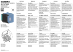
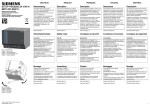
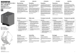
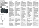
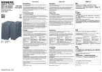
DEUTSCH
SITOP PSU400M 24 V/20 A
6EP1536-3AA00
Betriebsanleitung (kompakt)
Operating Instructions (compact)
Notice de service (compacte)
Istruzioni operative (descrizione sintetica)
Instrucciones de servicio (resumidas)
Bild 1: Ansicht Gerät
Figure 1: View of unit
Figure 1: Vue de l'appareil
Figura 1: Vista dell'apparecchio
Figura 1: Vista del aparato
Beschreibung
ENGLISH
Description
Die SITOP-Stromversorgungen
24 V/20 A sind Einbaugeräte, Schutzart
IP20, Schutzklasse I.
The 24 V/20 A SITOP power supplies
are built-in units, IP20 degree of
protection, protection class I.
Primär getaktete Stromversorgungen
zum Anschluss an 600 VDC
Zwischenkreis-Gleichstromnetz mit
Arbeitsspannungsbereich 200-900 VDC;
Ausgangsspannung +24 V DC,
potenzialfrei, kurzschluss- und
leerlauffest. (PELV)
Primary switched-mode power supplies
for connection to the 600 V DC
intermediate circuit DC network with a
working voltage range of 200-900 V DC;
output voltage of +24 V DC, isolated,
short-circuit proof and idling-proof.
(PELV)
FRANÇAIS
Description
Les alimentations SITOP 24 V/20 A sont
des appareils encastrables, avec degré
de protection IP20 et classe de
protection I.
Alimentations à découpage du primaire
pour raccordement à des réseaux
600 VCC de circuit intermédiaire avec
une plage de fonctionnement de 200 à
900 VCC ; tension de sortie +24 V CC,
avec séparation galvanique, protection
contre les courts-circuits et tenue à la
marche à vide. (TBTS)
ITALIANO
Descrizione
ESPAÑOL
Descripción
Gli alimentatori SITOP 24 V/20 A sono
apparecchi da incasso con grado di
protezione IP20 e classe di sicurezza I.
Las fuentes de alimentación SITOP de
24 V/20 A son aparatos con grado de
protección IP20 y clase de protección I.
Alimentatori a commutazione del
primario da collegare a una rete in
corrente continua di 600 VDC (circuito
intermedio) con un campo di tensione di
esercizio di 200-900 VDC; tensione di
uscita +24 V DC, con separazione di
potenziale, a prova di cortocircuito e
resistenti al funzionamento a vuoto.
(PELV)
Fuentes de alimentación conmutadas en
primario para conexión a una red de
corriente continua de 600 VDC (circuito
intermedio) con un rango de tensión
200-900 VDC; tensión de salida
+24 V DC, aislada galvánicamente,
protegida contra cortocircuito y marcha
en vacío. (PELV/MBTP)
Siehe auch Bild 1
See also Figure 1
Voir aussi Figure 1
Vedere anche Figura 1
Consulte también Figura 1
Sicherheitshinweise
Safety notes
Consignes de sécurité
Avvertenze di sicurezza
Consignas de seguridad
ACHTUNG
NOTICE
IMPORTANT
ATTENZIONE
ATENCIÓN
Der einwandfreie und sichere Betrieb
dieses Gerätes/Systems setzt
sachgemäßen Transport, sachgemäße
Lagerung, Aufstellung und Montage
sowie sorgfältige Bedienung und
Instandhaltung voraus.
Dieses Gerät/System darf nur unter
Beachtung der Instruktionen und
Warnhinweise der zugehörigen
Technischen Dokumentation eingerichtet
und betrieben werden.
Nur qualifiziertes Personal darf das
Gerät/System installieren und in Betrieb
setzen.
Warnung: Spannungseinstellung nur für
Erstinstallation verwenden
Appropriate transport, proper storage,
mounting, and installation, as well as
careful operation and service, are
essential for the error-free, safe and
reliable operation of the device/system.
Setup and operation of this
device/system are permitted only if the
instructions and warnings of the
corresponding documentation are
observed.
Only qualified personnel are allowed to
install the device/system and set it into
operation.
Warning: Use voltage setting only for first
installation
L'exploitation de cet appareil / ce
système dans les meilleures conditions
de fonctionnement et de sécurité
suppose un transport, un stockage, une
installation et un montage adéquats,
ainsi qu'une manipulation soigneuse et
un entretien rigoureux.
Cet appareil / ce système ne peut être
configuré et exploité qu'à condition de
respecter les instructions et les
avertissements figurant dans la
documentation technique
correspondante.
L'installation et la mise en service de
l'appareil / du système doit
impérativement être effectué par des
personnes qualifiées.
Attention : Procéder au réglage de la
tension uniquement lors de la première
installation
Il funzionamento ineccepibile e sicuro di
questo apparecchio/sistema presuppone
un trasporto corretto, un
immagazzinaggio idoneo, una
installazione, un montaggio, un utilizzo e
una manutenzione accurati.
Questo apparecchio/sistema deve
essere installato e impiegato nel pieno
rispetto delle istruzioni e delle
avvertenze riportate nella
documentazione tecnica pertinente.
L'apparecchio/il sistema può essere
installato e messo in servizio solo da
personale qualificato.
Attenzione: Utilizzare l'impostazione di
tensione solo per la prima installazione
El funcionamiento correcto y seguro de
este aparato/sistema presupone un
transporte, un almacenamiento, una
instalación y un montaje conformes a las
prácticas de la buena ingeniería, así
como un manejo y un mantenimiento
rigurosos.
Este aparato/sistema debe ajustarse y
utilizarse únicamente teniendo en cuenta
las instrucciones y advertencias de la
documentación técnica correspondiente.
La instalación y puesta en marcha del
aparato/sistema debe encomendarse
exclusivamente a personal cualificado.
Advertencia: El ajuste de tensión sólo
debe usarse durante la primera
instalación
Montage
Assembling
Fixation
Montage auf Normprofilschiene
DIN EN 60715-TH35-15/7,5.
Mounting on standard mounting rail
DIN EN 60715-TH35-15/7.5.
Fixation sur rail symétrique
DIN EN 60715-TH35-15/7,5.
Das Gerät ist so zu montieren, dass die
Eingangsklemmen unten und die
Ausgangsklemmen unten sind.
The device must be mounted in such a
way that the input terminals and the
output terminals are at the bottom.
L'appareil doit être fixé de sorte que les
bornes d'entrée et les bornes de sortie
se trouvent en bas.
Unterhalb und oberhalb des Gerätes
muss mindestens ein Freiraum von je
50 mm eingehalten werden.
A clearance of at least 50 mm must be
maintained above and below the device.
Un espace libre de 50 mm doit être
prévu en dessous et au dessus de
l'appareil.
Bei Einbau in Windkraftanlagen ist das
Gerät nur in LPZ2 nach IEC 61400-24 zu
betreiben.
When installed in wind power plants, the
device should only be operated in LPZ2,
in accordance with IEC 61400-24.
Lors de son installation dans des
éoliennes, l'appareil doit être exploité en
zone LPZ2 selon CEI 61400-24.
Montaggio
Montaggio su guida profilata
normalizzata
DIN EN 60715-TH35-15/7,5.
L'apparecchio va montato con i morsetti
d'ingresso in basso e i morsetti di uscita
in basso.
Sopra e sotto l'apparecchio deve restare
uno spazio libero di almeno 50 mm.
Se installato in impianti eolici,
l'alimentatore può essere impiegato solo
in LPZ2 (Lightning Protection Zone)
secondo IEC 61400-24.
Montaje
Fijación sobre perfil
DIN EN 60715-TH35-15/7,5.
El aparato debe montarse de modo que
los bornes de entrada queden abajo y
los de salida abajo.
Por encima y por debajo del aparato
debe dejarse un espacio libre de al
menos 50 mm.
Instalada en aerogeneradores eólicos, la
fuente sólo puede operarse en LPZ2
según IEC 61400-24.
Siehe auch Bild 2
See also Figure 2
Voir aussi Figure 2
Vedere anche Figura 2
Consulte también Figura 2
Siehe auch Bild 6
See also Figure 6
Voir aussi Figure 6
Vedere anche Figura 6
Consulte también Figura 6
Bild 2: Montage
Figure 2: Mounting
Figure 2: Fixation
Figura 2: Montaggio
Figura 2: Montaje
© Siemens Ⓟ2011
C98130-A7601-A1-2-6419, 8.2011
1
Anschließen
WARNUNG
Bild 3: Input ①
Figure 3: Input ①
Figure 3: Input ①
Figura 3: Input ①
Figura 3: Entrada ①
Bild 4: Output ②
Figure 4: Output ②
Figure 4: Output ②
Figura 4: Output ②
Figura 4: Salida ②
2
WARNING
Raccordement
ATTENTION
Collegamento
AVVERTENZA
Conexión
ADVERTENCIA
Vor Beginn der Installations- oder
Instandhaltungsarbeiten ist der
Hauptschalter der Anlage auszuschalten
und gegen Wiedereinschalten zu
sichern. Bei Nichtbeachtung kann das
Berühren spannungsführender Teile Tod
oder schwere Körperverletzung zur
Folge haben.
Die Betätigung des Potentiometers ist
nur mittels isoliertem Schraubendreher
zulässig.
Before installation or maintenance work
can begin, the system's main switch
must be switched off and measures
taken to prevent it being switched on
again. If this instruction is not observed,
touching live parts can result in death or
serious injury.
Actuation of the potentiometer is allowed
only be means of an insulated
screwdriver.
Avant de commencer les travaux
d'installation ou de maintenance, couper
l'interrupteur général de l'installation et le
condamner pour empêcher la remise
sous tension. Le non-respect de cette
consigne peut entraîner la mort ou des
blessures graves en cas de contact avec
des pièces sous tension.
Actionner le potentiomètre uniquement à
l'aide d'un tournevis isolé.
Prima dell'inizio dei lavori di installazione
o manutenzione è necessario disinserire
l'interruttore principale dell'impianto e
assicurarlo contro la reinserzione. In
caso di mancata osservanza, il contatto
con parti sotto tensione può provocare la
morte o gravi lesioni personali.
È consentito azionare il potenziometro
solo utilizzando un cacciavite isolato.
Antes de comenzar los trabajos de
instalación o mantenimiento, se deberá
abrir el interruptor principal del
cuadro/tablero y protegerlo para evitar
su cierre. Si no se observa esta medida,
el contacto con piezas bajo tensión
puede provocar la muerte o lesiones
graves.
El potenciómetro sólo deberá girarse
usando un destornillador aislado.
Für die Installation der Geräte sind die
einschlägigen länderspezifischen
Vorschriften zu beachten.
For installation of the devices, the
relevant country-specific regulations
must be observed.
L'installation des appareils doit se faire
en conformité avec les prescriptions
nationales.
Per l'installazione degli apparecchi
occorre osservare le normative nazionali
vigenti.
A la hora de instalar los aparatos, se
tienen que observar las disposiciones o
normativas específicas de cada país.
Wichtiger Hinweis: Eingangsseitig ist
eine kurzschlussfeste Zuleitung
vorzusehen.
Important note: A short-circuit proof
supply line must be provided on the input
side.
Remarque importante : un câble de
raccordement résistant aux courtscircuits doit être prévu en entrée.
Avvertenza importante: sul lato
d'ingresso si deve predisporre un cavo di
alimentazione a prova di cortocircuito.
Nota importante: en el lado de entrada
debe preverse un cable de alimentación
resistente a cortocircuitos.
Der Anschluss der
Versorgungsspannung (DC 600 V) muss
gemäß IEC 60364 und EN 50178
ausgeführt werden.
The connection of the supply voltage
(600 V DC) must be designed in
accordance with IEC 60364 and EN
50178.
Le raccordement de la tension
d'alimentation (600V CC) doit être
effectué conformément à CEI 60364 et
EN 50178.
Il collegamento della tensione di
alimentazione (DC 600 V) deve essere
eseguito in conformità alle norme
IEC 60364 ed EN 50178.
La conexión de la alimentación
(600 V DC) debe efectuarse conforme a
las normas IEC 60364 y EN 50178.
Siehe auch Bild 3
See also Figure 3
Voir aussi Figure 3
Vedere anche Figura 3
Consulte también Figura 3
Siehe auch Bild 4
See also Figure 4
Voir aussi Figure 4
Vedere anche Figura 4
Consulte también Figura 4
Siehe auch Bild 5
See also Figure 5
Voir aussi Figure 5
Vedere anche Figura 5
Consulte también Figura 5
Aufbau
Structure
Constitution
Struttura
Diseño
① DC-Eingang
① DC input
① Entrée CC
① Ingresso DC
① Entrada DC
② DC-Ausgang
② DC output
② Sortie CC
② Uscita DC
② Salida DC
③ Meldekontakte 13 – 14
③ Signaling contacts 13 - 14
③ Contacts de signalisation 13 – 14
③ Contatti di segnalazione 13 – 14
③ Contactos de señalización 13 – 14
④ Potentiometer 24 – 28,8 V
④ Potentiometer 24 - 28.8 V
④ Potentiomètre 24 – 28,8 V
④ Potenziometro 24 – 28,8 V
④ Potenciómetro 24 – 28,8 V
⑤ Kontrollleuchten (24 V O.K.,
⑤ Pilot lamps (24 V O.K., OVERLOAD,
⑤ Témoins (24 V O.K., OVERLOAD,
⑤ Spie di controllo (24 V O.K.,
⑤ Pilotos de control (24 V O.K.,
⑥ Wahlschalter
⑥ Selector switch
⑥ Sélecteur
⑥ Selettore
⑥ Selector
⑦ Tragschienenadapter
⑦ DIN rail adapter
⑦ Adaptateur sur rail support
⑦ Adattatore per guida DIN
⑦ Adaptador para perfil
⑧ Konvektion
⑧ Convection
⑧ Convection
⑧ Convezione
⑧ Convección
⑨ Freiraum oberhalb/unterhalb
⑨ Clearance above/below
⑨ Espace libre au dessus/en dessous
⑨ Spazio libero superiore/inferiore
⑨ Espacio libre arriba/abajo
OVERLOAD, SHUT DOWN)
Bild 5: Klemmendaten
Figure 5: Terminal data
Figure 5: Caractéristiques des bornes
Figura 5: Dati dei morsetti
Figura 5: Datos de los bornes
Connecting
Siehe auch Bild 6
SHUT DOWN)
See also Figure 6
SHUT DOWN)
Voir aussi Figure 6
OVERLOAD, SHUT DOWN)
Vedere anche Figura 6
OVERLOAD, SHUT DOWN)
Consulte también Figura 6
C98130-A7601-A1-2-6419, 8.2011
Betriebsmodus
Bild 7: Signalisierung
Figure 7: Signaling
Figure 7: Signalisation
Figura 7: Segnalazione
Figura 7: Señalización
Modo de servicio
Signalisation
Segnalazione
Señalización
LED grün: Ausgangsspannung O.K.
LED green: Output voltage O.K.
LED verte : tension de sortie O.K.
LED verde: Tensione di uscita O.K.
LED verde: tensión de salida OK
LED grün blinkend: verzögerter Start
LED flashing green: Delayed start
LED verde lampeggiante: Avvio ritardato
LED gelb: Überlast (Kurzschluss = KS)
LED yellow: Overload (short-circuit)
LED verte clignotante : démarrage
retardé
LED verde intermitente: arranque
retardado
LED rot: Speichernde Abschaltung (KS)
LED red: Latching shutdown (short
circuit)
LED jaune : Surcharge (court-circuit =
KS)
LED rosso: Disinserzione con
memorizzazione (cortocircuito):
LED giallo: Sovraccarico (cortocircuito)
LED amarillo: sobrecarga (cortocircuito
= KS)
LED flashing red: Overtemperature
LED rouge : Coupure mémorisée (KS)
LED rouge clignotante : Surchauffe
LED rosso lampeggiante:
Sovratemperatura
Wahlschalter Betriebsmodus
Operating mode selector switch
Sélecteur du mode de fonctionnement
Selettore del modo operativo
(A) Parallel- oder Einzelbetrieb
(A) Parallel or single mode
(A) Mode parallèle ou unique
(A) Funzionamento in parallelo o singolo
Selector de modpo de operación
(B) U/I Kennlinie oder Abschaltung
(B) U/I characteristic or shutdown
(B) Caractéristique U/I ou coupure
(A) Funcionamiento en paralelo o simple
(C) Startverzögerung 10 s
(C) Start delay 10 s
(C) Retard au démarrage 10 s
(B) Curva caratteristica U/I o
disinserzione
(B) Característica U/I o desconexión
(C) Avvio ritardato 10 s
(C) Retardo de arranque 10 s
Meldesignale
Status signals
Signalisations
Segnali
Señalización
Meldekontakt: Ausgangsspannung O.K.
Signaling contact: Output voltage O.K.
AC 30 V/0,5 A DC 60 V/0,3 A
DC 30 V/1 A
30 V AC/0.5 A 60 V DC/0.3 A
30 V DC/1 A
Contact de signalisation : tension de
sortie O.K.
Contatto di segnalazione: Tensione di
uscita O.K.
Contacto de señalización: Tensión de
salida OK
CA 30 V / 0,5 A CC 60 V / 0,3 A
CC 30 V / 1 A
AC 30 V/0,5 A DC 60 V/0,3 A
DC 30 V/1 A
AC 30 V/0,5 A DC 60 V/0,3 A
DC 30 V/1 A
LED rojo: desconexión que precisa
rearme (KS)
LED rojo intermitente: sobretemperatura
Siehe auch Bild 7
See also Figure 7
Voir aussi Figure 7
Vedere anche Figura 7
Consulte también Figura 7
Siehe auch Bild 8
See also Figure 8
Voir aussi Figure 8
Vedere anche Figura 8
Consulte también Figura 8
Technische Daten
Technical data
Caractéristiques techniques Dati tecnici
Datos técnicos
① Eingangsgrößen
① Input variables
① Valeurs d'entrée
① Grandezze di ingresso
① Magnitudes de entrada
Eingangsnennspannung Ue nenn:
DC 600 V
Rated input voltage Uin rated:
600 V DC
Tension d'entrée nominale Ue nom :
600 V CC
Tensione nominale di ingresso Uin nom:
DC 600 V
Tensión nominal de entrada Ue nom:
600 V DC
Eingangsspannungsbereich:
DC 200-900 V
Input voltage range:
200-900 V DC
Plage de tension d'entrée :
200-900 V CC
Campo di tensione di ingresso:
DC 200-900 V
Rango de tensión de entrada:
200-900 V DC
Eingangsnennstrom Ie nenn: 0,85 A
Rated input current Iin rated: 0.85 A
Courant d'entrée nominal Ie nom : 0,85 A
Corrente nominale di ingresso Iin nom: 0,85 A
Intensidad nominal de entrada Ie nom 0,85 A
Das Gerät ist nach dem DC-Freischalter
parallel zum Wechselrichter
anzuschließen.
The device is to be connected to the
inverter in parallel after the DC isolator.
L'appareil doit être raccordé en aval du
sectionneur CC en parallèle à l'onduleur.
Hot-Plug-In and Hot-Plug-Out is not
permitted.
Hot-Plug-In et Hot-Plug-Out n’est pas
permis.
L'apparecchio deve essere collegato in
parallelo con l'inverter dopo il sezionatore
DC.
El aparato debe conectarse en paralelo
con el inversor aguas abajo del
seccionador DC.
Hot-Plug-In e Hot-Plug-Out é vietato.
In other applications, a surge arrester
and/or an EMC filter may have to be
connected upstream.
Dans d'autres types d'application, il
convient de placer un parasurtenseur
et/ou un filtre CEM en amont.
In altre applicazioni si deve eventualmente
inserire a monte uno scaricatore di
sovratensione e/o un filtro EMC.
Hot-Plug-In y Hot-Plug-Out no está
permitido.
The supply line should be designed to
be short-circuit proof.
Le câble d'alimentation doit être
résistant aux courts-circuits.
Il cavo di alimentazione deve essere
installato a prova di cortocircuito.
The breaking capacity of the internal
fuse is 20 kA; L/R < 2 ms
Le pouvoir de coupure du fusible interne
est de 20 kA; L/R < 2 ms
Il potere di interruzione del fusibile interno
ammonta a 20 kA; L/R < 2 ms
d
El cable de alimentación deberá instalarse protegido contra contocircuitos.
Leistungsaufnahme (Wirkleistung) bei
Volllast: 505 W
Power consumption (active power) at full
load: 505 W
Puissance absorbée (puissance active)
à pleine charge : 505 W
Potenza assorbita a pieno carico
(potenza attiva): 505 W
Consumo (potencia activa) a plena
carga: 505 W
② Ausgangsgrößen
② Output variables
② Valeurs de sortie
② Grandezze di uscita
② Magnitudes de salida
Ausgangsnennspannung Ua nenn: 24 V
(Auslieferzustand)
Rated output voltage Uout rated : 24 V
(delivery state)
Tension de sortie nominale Us nom : 24 V
(état à la livraison)
Tensione nominale di uscita Uout nom:
24 V (stato di fornitura)
Tensión nominal de salida Us nom: 24 V
(ajuste de fábrica)
Einstellbereich: 24-28,8 V, Einstellung
über Potentiometer ④ an der
Gerätevorderseite
Setting range: 24-28.8 V, set via
potentiometer ④ at the device front
Plage de réglage : 24-28,8 V, réglage
par potentiomètre ④ en face avant de
l'appareil
Campo di regolazione: 24-28,8 V,
impostazione tramite potenziometro ④
sul lato frontale dell'apparecchio
Rango de ajuste: 24-28,8 V, ajuste con
potenciómetro ④ en el frontal del
aparato
Derating bei
Derating for
Déclassement pour
Derating con
Derating con
Ua > 24 V: 4 % Ia bzw. 3 °C tamb / V Ua
60-70 °C tamb : Ia = siehe Manual
Uin < 300 VDC: Ia = 10 A / 2 min max.
Uin > 820 VDC: Ia = siehe Manual
Uout > 24 V: 4% Iout or 3 °C tamb / V Uout
60-70 °C tamb: Iout = see Manual
Uin < 300 V DC: Iout = 10 A / 2 min max.
Uin > 820 V DC: Iout = see Manual
Usortie >24 V : 4% Isortie ou 3°C tamb/V Usortie
60-70 °C tamb : Ia = voir manuel
Uentrée < 300 VCC : Ia = 10 A / 2 min max.
Uentrée > 820 VCC : Isortie = voir manuel
Uout > 24 V: 4 % Iout risp.3 °C tamb / V Uout
60-70 °C tamb : Iout = vedi il manuale
Uin < 300 VDC: Iout = 10 A / 2 min max.
Uin > 820 VDC: Iout = vedi il manuale
Us > 24 V: 4 % Ias o bien 3 °C tamb / V Us
60-70 °C tamb : Is = ver Manual
Uen < 300 VDC: Is = 10 A / 2 mín máx.
Uen > 820 VDC: Ia = ver Manual
Ausgangsnennstrom Ia nenn: 20 A
Rated output current Iout rated: 20 A
Courant de sortie nominal Ia nom: 20 A
Corrente nominale di uscita Iout nom: 20 A
Corriente nominal de salida Is nom: 20 A
Hot-Plug-In und Hot-Plug-Out ist nicht
zulässig.
Die Zuleitung ist kurzschlussfest
auszuführen.
Das Abschaltvermögen der internen
Sicherung beträgt 20 kA; L/R < 2 ms
C98130-A7601-A1-2-6419, 8.2011
Modo operativo
Signaling
In anderen Anwendungen ist eventuell
ein Überspannungsableiter und/oder ein
EMV-Filter vorzuschalten.
Bild 8: Meldekontakt ③ und Wahlschalter ⑥
Figure 8: Signaling contact ③ and selector switch ⑥
Figure 8: Contact de signalisation ③ et sélecteur ⑥
Figura 8: Contatto di segnalazione ③ e selettore ⑥
Figura 8: Contacto de señalización ③ y selector ⑥
Mode de fonctionnement
Signalisierung
LED rot blinkend: Übertemperatur
Bild 6: Gesamtaufbau
Figure 6: Overall structure
Figure 6: Constitution
Figura 6: Struttura completa
Figura 6: Diseño general
Operating mode
En otras aplicaciones puede ser
necesario instalar un descargador de
sobretensiones y/o un filtro para mejorar
la compatibilidad electromagnética.
El poder de corte de la protección
interna es de 20 kA; L/R < 2 ms
3
Extra Power beim Einschalten und im
Betrieb: 30 A für 5 s (pro min)
Extra power during switch-on and
operation: 30 A for 5 s (pro min)
Puissance supplémentaire à la mise en
marche et en service : 30 A pendant 5 s
(par min)
Extra Power all'inserzione e in esercizio:
30 A per 5 s (al minuto)
Potencia adicional al conectar y en
servicio: 30 A durante 5 s (por min)
Umgebungsbedingungen
Ambient conditions
Conditions ambiantes
Condizioni ambientali
Condiciones ambientales
Temperatur für Betrieb:
-25…+70 °C
Temperature for operation:
-25…+70 °C
Température de fonctionnement 25…+70 °C
Temperatura in esercizio:
-25…+70 °C
Temperatura de funcionamiento: 25…+70 °C
Eigenkonvektion
Natural convection
Convection naturelle
Convezione naturale
Convección natural
Schutzfunktion
Protective function
Fonction de protection
Funzione di protezione
Función de protección
Strombegrenzung bei permanenter
Überlast (>5 s),
Ansprechwert: < 1,1 × Ia nenn,
ausgenommen während Power Boost
Abschaltung bei Uin > 900 VDC
Current limitation at permanent overload
(> 5 s),
response value: < 1.1 × Iout rated, apart
from during Power Boost
Shutdown at Uin > 900 V DC
Limitation de courant pour surcharge
permanente (> 5 s),
seuil de réponse : < 1,1 × Isortie nom, sauf
pendant le power boost
Coupure pour Uentrée > 900 VCC
Limitazione di corrente con sovraccarico
permanente (>5 s),
valore di intervento: < 1,1 × Iout nom,
tranne durante un Power Boost
Disinserzione con Uin > 900 VDC
Limitación de corriente con sobrecarga
permanente (> 5 s),
valor de reacción: < 1,1 × Is nom,
exceptuando durante el Power Boost
Desconexión con Uen > 900 VDC
ACHTUNG:
Wiederanlauf bei Uin < 820 VDC
Temperaturabschaltung
Ausgang einseitig erden (PELV) bei
Wechselrichteranwendung
CAUTION:
Restart at Uin < 820 V DC
Temperature shutdown
Ground output on one side (PELV) for
inverter usage
IMPORTANT :
Redémarrage pour Uentrée < 820 VCC
Coupure pour surchauffe
Dans le cas des applications d'onduleur,
mettre à la terre la sortie sur une
extrémité (TBTS)
ATTENZIONE:
Riavviamento con Uin < 820 VDC
Disinserzione per temperatura
In applicazioni con invertitori, mettere a
terra l'uscita (PELV) unilateralmente
ATENCIÓN:
rearranque con Uen < 820 VDC
Desconexión por temperatura
En aplicaciones con inversores, poner a
tierra la salida (PELV/MBTP)
Kennlinie der Strombegrenzung stetig
abfallend oder Abschaltung (wählbar)
Characteristic of current limitation
constantly dropping or shutdown (can be
selected)
Caractéristique continue de la limitation
de courant en pente descendante ou
coupure (sélectionnable)
Curva caratteristica della limitazione di
corrente costantemente decrescente o
disinserzione (selezionabile)
Característica de la limitación de
corriente: monótona decreciente o
desconexión (a elección)
Abmessungen
Dimensions
Dimensions
Dimensioni
Dimensiones
Höhe × Breite × Tiefe in mm:
125 × 90 × 125
Width × height × depth in mm:
125 × 90 × 125
Hauteur × largeur × profondeur en mm :
125 × 90 × 125
Altezza × larghezza × profondità in mm:
125 × 90 × 125
Altura x anchura × profundidad en mm:
125 × 90 × 125
Entsorgungsrichtlinie
Verpackung und Packhilfsmittel sind
recyclingfähig und sollten grundsätzlich
der Wiederverwertung zugeführt werden.
Das Produkt selbst darf nicht über den
Hausmüll entsorgt werden.
Zubehör
Funktionserweiterung durch
Ergänzungsmodule Redundanzmodul,
Diagnosemodul SITOP select oder DC
USV möglich
www.siemens.de/sitop
Service und Support
4
Disposal guideline
Packaging and packaging aids can and
must always be recycled. The product
itself may not be disposed of by means
of domestic refuse.
Accessories
Function expansion possible through
add-on modules: redundancy module,
diagnostics module SITOP select or DC
UPS
www.siemens.de/sitop
Service and Support
Directive de recyclage
L'appareil et son emballage sont tous
recyclables et doivent donc être traités
par une filière de recyclage. Il est interdit
de se débarrasser de l'appareil via les
déchets domestiques.
Accessoires
L'extension fonctionnelle est possible au
moyen des modules d'extension module
de redondance, module de diagnostic
SITOP select ou CD USV (ASI)
www.siemens.com/sitop
SAV et assistance
Direttiva sullo
smaltimento
L'imballaggio e i materiali ausiliari di
imballaggio utilizzati sono riciclabili e
devono quindi essere destinati al
riciclaggio. Questo prodotto non deve
essere smaltito con i rifiuti ordinari.
Accessori
Ampliamento delle funzioni tramite
moduli aggiuntivi: modulo di ridondanza,
modulo di diagnostica SITOP select o
modulo DC UPS
www.siemens.de/sitop
Service & Support
Directiva de eliminación
de residuos
Todo el material usado para el embalaje
es reciclable, por lo que debería
separarse para su reutilización. El
producto propiamente dicho no deberá
eliminarse a través de la basura
doméstica.
Accesorios
Es posible una ampliación funcional
mediante módulos complementarios:
módulo de redundancia, módulo de
diagnóstico SITOP select o DC USV
(SAI DC)
www.siemens.de/sitop
Servicio técnico y
asistencia
http://support.automation.siemens.com
http://support.automation.siemens.com
http://support.automation.siemens.com
http://support.automation.siemens.com
http://support.automation.siemens.com
Telefon: + 49 (0) 911 895 7222
Telephone: + 49 (0) 911 895 7222
Téléphone : + 49 (0) 911 895 7222
Telefono: + 49 (0) 911 895 7222
Teléfono: + 49 (0) 911 895 7222
C98130-A7601-A1-2-6419, 8.2011