1
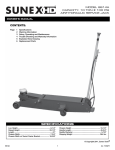
MODEL 6609
CAPACITY: 10 TON
HYDRAULIC SERVICE JACK
OWNER'S MANUAL
CONTENTS:
Page
1
2
3
4
5
6
Specifications and Features
Warning Information
Setup, Operating and Maintenance
Trouble Shooting and Warranty Information
Exploded View Drawing
Replacement Parts
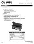
FEATURES:
•Uniweld constructed hydraulic assembly for increased strength and eliminates leaking.
•Flash chromed ram and pump piston inhibit rust.
•Foot pump pedal for quickly raising the lift arm to the load.
•Locking lever on "T" handle locks handle in three different positions.
•Release knob on top of handle operates independent of handle locking lever.
•Safety by-pass and overload systems prevent over extending ram and
prevents jack from being used beyond its rated capacity.
•Full swivel ball bearing caster wheels with zerk grease fittings.
•Front wheels include roller bearings.
•Rear kick plate helps turn jack when in tight places.
SPECIFICATIONS
Low Height....................................................................... 6-1/4"
Raised Height................................................................22.375"
Length...................................................................................61"
Chassis Width.................................................................. 7-3/4"
Chassis Width w/ Swivel Caster Bracket....................18.375"
Handle Length............................................................... 45-3/4"
Saddle Diameter.............................................................. 5-7/8"
Shipping Weight........................................................... 338 lbs.
© Copyright 2008, Sunex Tools®
6609
1
rev. 09/26/08
Warning Information
This is the safety alert symbol. It is used to alert you
to potential personal injury hazards. Obey all safety
messages that follow this symbol to avoid possible
injury or death.
WARNING
WARNING: Indicates a hazardous situation
which, if not avoided, could result in death
or serious injury.
IMPORTANT: READ THESE INSTRUCTIONS BEFORE OPERATING
BEFORE USING THIS DEVICE, READ THIS MANUAL COMPLETELY AND THOROUGHLY. UNDERSTAND ITS OPERATING
PROCEDURES, SAFETY WARNINGS AND MAINTENANCE REQUIREMENTS.
It is the responsibility of the owner to make sure all personnel read this manual prior to using the device. It is also the responsiblity of
the device owner to keep this manual intact and in a convenient location for all to see and read. If the manual or product labels are lost
or not legible, contact Sunex for replacements. If the operator is not fluent in English, the product and safety instructions shall be read
to and discussed with the operator in the operator's native language by the purchaser/owner or his designee, making sure that the
operator comprehends its contents.
THE NATURE OF HAZARDOUS SITUATIONS
WARNING
The use of portable automotive lifting devices is subject to certain hazards that cannot be prevented by mechanical means, but only
by the exercise of intelligence, care, and common sense. It is therefore essential to have owners and personnel involved in the use and
operation of the equipment who are careful, competent, trained, and qualified in the safe operation of the equipment and its proper
use. Examples of hazards are dropping, tipping or slipping of loads caused primarily by improperly securing loads, overloading, offcentered loads, use on other than hard level surfaces, and using equipment for a purpose for which it was not designed.
METHODS TO AVOID HAZARDOUS SITUATIONS
WARNING
• Read, study, understand and follow all instructions before operating this device.
• Inspect the jack before each use. Do not use jack if damaged, altered, modified, in poor condition, leaking hydraulic fluid, or
unstable due to loose or missing hardware or parts. Make corrections before using.
• Lift only on areas of the vehicle as specified by the vehicle manufacturer.
• Wear eye protection that meets ANSI Z87.1 and OSHA standards.
• Do not use jack beyond its rated capacity.
• This is a lifting device only. Immediately after lifting, support the vehicle with jack stands capable of sustaining the load before working on the vehicle.
• Use only on a hard level surface free from obstructions so the jack is free to reposition itself during lifting and lowering operations.
• Center load on saddle. Be sure setup is stable before working on vehicle.
• Do not move or dolly the vehicle while on the jack.
• Do not use saddle adapters or saddle extenders between the stock lifting saddle and the load.
• Do not use any adapters unless approved or supplied by Sunex.
• Always lower the jack slowly and carefully.
• Failure to heed these markings may result in serious or fatal personal injury and/or property damage.
CONSEQUENCES OF NOT AVOIDING HAZARDOUS SITUATIONS
WARNING
Failure to read this manual completely and thoroughly, understand its OPERATING INSTRUCTIONS, SAFETY WARNINGS,
MAINTENANCE INSTRUCTIONS and not comply with them, and neglecting the METHODS TO AVOID HAZARDOUS SITUATIONS could
cause accidents resulting in serious or fatal personal injury and/or property damage.
6609
2
rev. 09/26/08
MODEL 6609
CAPACITY: 10 TON
HYDRAULIC SERVICE JACK
OWNER'S MANUAL
SETUP
PLEASE REFER TO THE EXPLODED VIEW DRAWING IN THIS MANUAL IN ORDER TO IDENTIFY PARTS.
1. In order to install the handle assembly item #54 in the handle socket item #32, first align the main handle tube with the largest hole in the handle socket and the lock pin rod with the smaller hole in the handle socket.
2. Make sure the lock pin rod is in the down/lock position before insertion in the handle socket. Once the main handle tube and lock pin rod are aligned with their respective holes in the handle socket, push the handle assembly in the handle socket so the end of the handle tube engages the release valve mechanism in the bottom of the handle socket and the lock pin rod engages one of the three (3) locking holes in the item #1 frame.
3. Now rotate the "T" handle portion of the handle assembly so it is perfectly aligned with the jack before tightening the item #36 bolt and item #34 nut. Tighten the bolt and nut so the handle can not rotate. Disengage the lock pin rod by pulling up on the lever and engaging the lever with the slot in top of the handle assembly. The handle assembly should be free to pump up and down.
4. In order to check for proper handle assembly alignment with the handle socket, see if the lock pin rod will engage with the three locking holes in the frame. Also, turn the release valve knob at the top of the handle assembly left and then right to see if the release valve u-joint in front and below the handle socket is rotating simultaneously with the turning of the knob.
5. Before Use: Air may become trapped in the hydraulic system.
PURGING AIR FROM THE HYDRAULIC SYSTEM:
a.
b.
c.
d.
e.
Rotate the knob at the top of the handle assembly in a clockwise direction until tight.
Now turn it in a counterclockwise direction two full turns.
Activate the foot pump pedal item #33 about 15 times.
Rotate the knob at the top of the handle assembly in a clockwise direction until tight.
Activate the foot pump until the lift arm is raised to maximum height. You should experience a full pump stroke with each incremental pump of the pedal.
If it does not feel your are getting full incremental pump stroke at anytime during the pumping operation, repeat steps "a" through "d" until all air is purged from the system.
OPERATING INSTRUCTIONS
This is the safety alert symbol used for the OPERATING INSTRUCTIONS section of this manual to alert you to potential personal injury hazards. Obey all instructions to avoid possible injury or death.
IMPORTANT: Before attempting to raise any vehicle, check vehicle service manual for recommended lifting surfaces.
OPERATION:
1. To raise load: Turn the knob at the top of the handle assembly in a clockwise direction until tight. Position the jack under the load.
Proceed to pump the handle or the foot pedal in order to raise the lift arm to the load. As the saddle at the end of the lift arm gets closer
to the load, reposition the jack so the saddle will contact the load firmly and the load is centered on the saddle. Make sure the saddle is correctly positioned. Remember that foot pedal pump operation is only used to quickly raise the saddle to the load. The handle pump
operation of the jack is used to lift the load. Raise the load to the desired work height. Place jack stands of appropriate capacity at the vehicle manufacturers's recommended support areas that provide stable support for the raised vehicle. DO NOT CRAWL UNDER
VEHICLE WHILE LIFTING VEHICLE OR REMOVING THE JACK STANDS! Once jack stands are positioned, turn the knob at the top of the handle assembly VERY SLOWLY. Lower the load to rest on the jack stands. Inspect the relationship between the jack stands and load
to make sure the setup is stable and safe. If the setup is not stable or safe follow the preceding steps until corrected. NOTE. Once the hand pump operation has ceased, the handle assembly can be locked in any of the three (3) handle locking positions. Typically, the handle
locking positions are used for moving the jack around the shop, keeping the handle out of the way or preventing the handle from being pumped.
2. To lower load: Follow the procedures mentioned in "To raise load" section of the OPERATING INSTRUCTIONS in order to raise the load off the jack stands. Once the load has cleared the jack stands, remove the stands from under the load and away from the work area. Turn the knob at the top of the jack's handle assembly very slowly in a counterclockwise direction until the load is completely lowered to the ground. Once the jack's lifting saddle has cleared the load, remove the jack from under the load.
CAUTION: Keep hands and feet away from the hinge mechanism of the jack.
PREVENTATIVE MAINTENANCE
1. 2. This is the safety alert symbol used for the PREVENTATIVE MAINTENANCE section of this manual to alert you to potential personal injury hazards. Obey all instructions to avoid possible injury or death.
Always store the jack in a well protected area where it will not be exposed to inclement weather, corrosive vapors, abrasive dust, or any other harmful elements. The jack must be cleaned of water, snow, sand or grit before using.
The jack must be lubricated periodically in order to prevent premature wearing of parts. A general purpose grease must be applied to all zerk grease fittings, caster wheels, front axle wheels, elevator arm, handle base pivot bolts, release mechanism and all other bearing
surfaces.
6609
3
rev. 09/26/08
PREVENTATIVE MAINTENANCE (CONT.)
3. It should not be necessary to refill or top off the reservoir with hydraulic fluid unless there is an external leak. An external leak requires
immediate repair which must be performed in a dirt-free environment by an authorized service center.
IMPORTANT: In order to prevent seal damage and jack failure, never use alcohol, hydraulic brake fluid or transmission oil in the jack.
4. Every jack owner is responsible for keeping the jack labels clean and readable. Use a mild soap solution to wash external surfaces of the jack but not any moving hydraulic components.
5.Inspect the jack before each use. Do not use the jack if any component is cracked, broken, bent, shows sign of damage or leaks hydraulic fluid. Do not use the jack if it has loose or missing hardware or components, or is modified in any way. Take corrective action before using the jack again.
6. Any hydraulic repairs within the warranty period must be performed by an authorized service center.
troubleshooting
Problem
Action
1. Unit will not lift load.
Purge air from hydraulic system by following procedure
under SETUP.
2. Unit will not sustain load or feels “spongy” under load.
Purge air from hydraulic system as above.
3. Unit will not lift to full height.
Purge air from hydraulic system as above.
4. Handle tends to raise up while the unit is under load.
Pump the handle rapidly several times to push oil past ball
valves in power unit.
5. Unit still does not operate.
Contact an authorized service center from enclosed list.
LIMITED WARRANTY
SUNEX INTERNATIONAL, INC. WARRANTS TO ITS CUSTOMERS THAT THE COMPANY’S SUNEX TOOLS® BRANDED
PRODUCTS ARE FREE FROM DEFECTS IN WORKMANSHIP AND MATERIALS.
Sunex International, Inc. will repair or replace its Sunex Tools® branded products which fail to give satisfactory service due to defective workmanship or materials, based
upon the terms and conditions of the following described warranty plans attributed to that specific product.
This product carries a ONE-YEAR warranty. During this warranty period, Sunex Tools will repair or replace at our option any part or unit which proves to be defective in
material or workmanship.
Other important warranty information
This warranty does not cover damage to equipment or tools arising from alteration, abuse, misuse, damage and does not cover any repairs or replacement made by anyone other than Sunex Tools or its authorized warranty service centers.
The foregoing obligation is Sunex Tools’ sole liability under this or any implied warranty and under no
circumstances shall we be liable for any incidental or consequential damages.
Note: Some states do not allow the exclusion or limitation of incidental or consequential damages, so the above limitation or exclusion may not apply to you.
Return equipment or parts to an authorized service center, transportation prepaid. Be certain to include your name and address, evidence of the purchase date, and
description of the suspected defect. If you have any questions about warranty service, please write to Sunex Tools. This warranty gives you specific legal rights and you
may also have other rights which vary from state to state.
Repair kits and replacement parts are available for many of Sunex Tools products regardless of whether or not the product is still covered by a warranty plan.
6609
SHIPPING ADDRESS:
MAILING ADDRESS:
Sunex Tools
315 Hawkins Rd.
Travelers Rest, South Carolina 29690
Sunex Tools
P.O. Box 1233
Travelers Rest, South Carolina 29690
4
rev. 09/26/08
MODEL 6609
CAPACITY: 10 TON
HYDRAULIC SERVICE JACK
Parts list and drawing
22
21
20
16
15
19
18
14
17
13
12
54
23
11
Power unit
RS660955
7
5
8
25
10
9
RS660954
24
12
26
27
39
6
38
4
3
40
49
2
2
1
41
31
55
51
42
43
44
44
37
55
27 28
47
29
30
48
46
45
50
52
24
36
35
26
50
34
33
25
12
13
7
6
23
14
15
32
25
22
21
11
20
53
8
19
5
14
18
13
16
9
17
10
5
1
2
3
3A
2
4
6609
5
rev. 09/26/08
MODEL 6609
CAPACITY: 10 TON
HYDRAULIC SERVICE JACK
Parts list and drawing
Index No. Part No. Description
1
2
3
RS660903
3A
RS660903A
4
5
6
7
8
RS660908
9
10
11
12
13
14
15
16
RS660916
17
RS660917
18
19
20
21
22
23
24
RS660929
25
RS550510
26
RS550509
27
28
29
30
Frame
Washer
Front wheel (incl. #2,3,3a,4,5)
Roller bearing set
Snap ring
Grease fitting
Rod link
Bolt
Saddle
Lock washer
Nut
Spring
Bolt
Bolt
Lock washer
Shaft
Rear caster wheel assembly
Caster bolt kit [(incl. #17 (2), 18 (2)]
Washer
Snap ring
Pin
Washer
Pin
Link assembly
Spring
Snap ring
Pedal pin
Pin
Pin
Pin
Oil hydraulic assembly
Qty.
Index No. Part No. Description
1
4
2
2
2
5
2
2
1
2
2
1
1
2
2
1
2
4
4
2
1
1
1
1
1
2
1
1
1
1
1
31
32
RS660932
33
RS550511
34
35
36
RS550535
37
38
39
RS660939
40
41
42
43
44
45
46
47
RS660947
48
49
50
51
52
53
54
RS660954 55
RS660955
Qty.
Cover
Handle socket
Pedal
Nut
Washer
Bolt Kit (incl. #34,35,36)
Handle
Sleeve
Knob
Pin
Control rod
Spring
Washer
Bolt
Pin
Spring
Universal joint assembly
Convey rod
Washer
Pin
Pin
Washer
Snap ring
Handle assembly (incl. #37-45, 48-52)
Complete hydraulic block assembly
1
1
1
1
1
1
1
2
1
1
1
1
2
2
1
1
1
1
1
2
1
1
2
1
1
Only index numbers identified by part number are available separately.
Power unit
Index No. Part No. Description
1
*
Snap ring
2
*
Washer
3
*
O-ring
4
Piston rod
5
*
Piston ring
6
*
Sealing washer
7
*
O-ring
8
*
O-ring Retainer
9
*
Snap ring
10
Oil hydraulic assembly
11
*
Oil filler plug
12
*
Steel ball
13
*
Steel ball
Asterisked index numbers available in repair kit only, RS6609RK
6609
Qty.
Index No. Part No. Description
1
2
1
1
1
1
1
1
1
1
1
2
1
6
14
*
15
*
16
17
*
18
*
19
*
20
21
*
22
23
*
24
25
26
*
27
*
Spring
Copper washer
Bolt
Steel ball
Ball seat
Spring
Bolt
Sealing washer
Bolt
Sealing washer
Release valve rod
Cylinder pump
O-ring
Nylon gasket
Qty.
1
1
1
1
1
1
1
1
1
1
1
1
2
2
rev. 09/26/08
MODELO 6609
CAPACIDAD: 10 TONELADAS
GATO DE SERVICIO HIDRÁULICO
OWNER'S MANUAL
CONTENIDO:
Página
1
2
3
4
5
6
Especificaciones y características
Información de advertencia
Ensamble, operación y mantenimiento
Diagnóstico de averías e información de garantía
Dibujo de vista en detalle
Partes de reposición
CARACTERÍSTICAS:
•Montaje de construcción hidráulica de soldadura de una sola pieza para mayor resistencia y la eliminación de fugas.
•El pistón cromado y el pistón de bomba previenen la corrosión.
•Pedal de bomba de pie para la elevación rápida del brazo de levantamiento
hasta la altura de la carga.
•La palanca de seguridad en el mango en “T” bloquea el mango en tres
posiciones diferentes.
•La perilla de liberación en la parte superior del mango se opera
independientemente de la palanca de seguridad.
•Sistemas de sobrecarga y circunvalación previenen la sobre extensión
del eje y previene que el gato se opere
más allá de su capacidad nominal.
ESPECIFICACIONES
Altura baja........................................................................ 6-1/4"
Altura elevada................................................................22.375"
Longitud................................................................................61"
Anchura del chasis.......................................................... 7-3/4"
Anchura del chasis con ménsula
de ruedecilla giratoria...................................................18.375"
Longitud del mango ..................................................... 45-3/4"
Diámetro de la silla.......................................................... 5-7/8"
Peso de embarque....................................................... 338 lbs.
© Copyright 2008, Sunex Tools®
6609
7
rev. 09/26/08
Información de advertencia
Este símbolo indica una alerta de seguridad y se usa para
advertir sobre peligro de accidentes personales. Observe toda
la información de seguridad que sigue a este símbolo para
evitar la posibilidad de que ocurran lesiones o muerte.
PRECAUCIÓN
PRECAUCIÓN: Indica una situación
peligrosa que si no se evita, puede
provocar la muerte o lesiones graves.
IMPORTANTE: LEA ESTAS INSTRUCCIONES ANTES DE USAR EL DISPOSITIVO
ANTES DE USAR ESTE DISPOSITIVO, LEA ESTE MANUAL DETENIDAMENTE. PROCURE ENTENDER SUS PROCEDIMIENTOS
OPERATIVOS, ADVERTENCIAS DE SEGURIDAD Y FORMA DE MANTENIMIENTO.
El propietario es responsable de asegurarse de que todo el personal lea este manual antes de usar el dispositivo. Asimismo, es
responsabilidad del propietario mantener este manual en buenas condiciones en una ubicación conveniente para su consulta. Si las
etiquetas del manual o producto son ilegibles o no están en su lugar, deberá ponerse en contacto con Arcan para obtenerlas gratis.
El comprador/propietario o una persona designada deberá leer y comentar el producto y las advertencias de seguridad en la lengua
materna del operario que no hable inglés fluido, a fin de asegurarse de que comprende el contenido.
NATURALEZA DE LAS SITUACIONES DE RIESGO
PRECAUCIÓN
El uso de dispositivos de elevación de automotores se halla sujeto a ciertos riesgos que no se pueden prever por medios mecánicos,
sino por la información, la diligencia y el sentido común. Por lo tanto, es esencial que el uso del dispositivo quede en manos de los
propietarios y de personal que sea cuidadoso, competente, capacitado y habilitado para realizar una operación segura. Algunos
ejemplos de peligros son dejar caer, inclinar o resbalar las cargas, principalmente como consecuencia de una sujeción incorrecta,
sobrecarga, posición no centrada, uso en superficies no niveladas o firmes, así como usar el dispositivo con un fin para el que no está
diseñado.
FORMAS DE EVITAR LAS SITUACIONES DE RIESGO
PRECAUCIÓN
•
•
•
•
•
•
•
•
•
•
•
•
•
Lea, estudie, comprenda y observe todas las instrucciones antes de operar este dispositivo.
Verifique el gato antes de usarlo. No lo use si tiene roturas, alteraciones, fugas de líquido hidráulico o está en malas
condiciones, como tampoco si presenta inestabilidad debido a piezas metálicas o partes desajustadas o faltantes.
Tome las medidas de corrección apropiadas antes de usarlo.
Utilice el dispositivo de elevación únicamente en las áreas del vehículo especificadas por su fabricante.
Use protección para los ojos que cumpla con las normas ANSI Z87.1 y OSHA.
No use el gato para elevar pesos superiores a su capacidad.
Este dispositivo se debe utilizar únicamente para levantar cargas. No bien haya elevado la carga, sujete el vehículo
con torres que tengan la capacidad para sostenerlo antes de comenzar a trabajar.
Use el gato únicamente en superficies niveladas firmes en las que no haya obstáculos, de modo que el dispositivo
pueda posicionarse durante las operaciones de elevación y descenso.
Centre la carga en el asiento. Asegúrese de que el armado del dispositivo sea estable antes de comenzar a trabajar.
No mueva ni empuje el vehículo sobre el gato.
No utilice ningún tipo de adaptador ni extensión entre el asiento del gato y la carga.
No use adaptadores a menos que Arcan los haya aprobado o suministrado.
Baje el gato siempre despacio y con cuidado.
No cumplir con estas indicaciones puede provocar lesiones graves o peligro de muerte, así como daños materiales.
CONSECUENCIAS DE NO PREVENIR LAS SITUACIONES DE RIESGO
PRECAUCIÓN
No leer, comprender u observar todo el contenido de este manual en relación con sus INSTRUCCIONES DE USO, ADVERTENCIAS DE
SEGURIDAD y FORMA DE MANTENIMIENTO, así como desatender las FORMAS DE EVITAR LAS SITUACIONES DE RIESGO, puede
provocar accidentes que tengan como consecuencia lesiones graves, peligro de muerte o daños materiales.
6609
8
rev. 09/26/08
MODEL 6609
CAPACITY: 10 TON
HYDRAULIC SERVICE JACK
OWNER'S MANUAL
MONTAJE
CONSULTE POR FAVOR EL DIBUJO DE VISTA EN DETALLE EN ESTE MANUAL PARA IDENTIFICAR LAS PARTES.
1. Para poder instalar el conjunto del mango, artículo #59, en el casquillo del mango, artículo #37. Primero alinee el tubo del mango principal con el agujero más grande en el casquillo del mango y el pasador de seguridad con el agujero más pequeño en el casquillo del mango.
2. Antes de insertarlo en el casquillo del mango, asegúrese que el pasador de seguridad esté en la posición de seguridad/hacia abajo. Una vez que el tubo del mango principal y el pasador de seguridad estén alineados con sus agujeros respectivos en el casquillo del mango, empuje el conjunto del mango en el casquillo del mango con el fin de que el tubo del mango se encaje con el mecanismo de la válvula de liberación en la parte
inferior del casquillo del mango y el pasador de seguridad se encaje con alguno de los tres (3) agujeros de seguridad en el armazón
del artículo #1.
3. Ahora gire la parte del mango en "T" del conjunto del mango con el fin de que esté perfectamente alineada con el gato antes de apretar el perno, artículo #41 y la tuerca, artículo #39. Apriete el perno y la tuerca con el fin de no se pueda girar el mango. Desconecte el pasador de seguridad al jalar la palanca hacia arriba y al encajar la palanca con la ranura en parte superior del conjunto de mango. El conjunto del mango debe estar libre para bombear hacia arriba y hacia abajo.
4. Para poder inspeccionar la alineación adecuada del conjunto del mango con el casquillo del mango, verifique que el perno de seguridad se encaje con los tres agujeros de seguridad en el armazón. Además, gire la perilla de la válvula de liberación en la parte superior del conjunto del mango hacia la izquierda y luego hacia la derecha para verificar que la junta en “U” de la válvula de liberación, en frente de y debajo del casquillo del mango, se esté girando simultáneamente con la rotación de la perilla.
5. Antes del uso: El aire puede entraparse en el sistema hidráulico.
PARA PURGAR EL AIRE DEL SISTEMA HIDRÁULICO:
a.
b.
c.
d.
e.
Gire la perilla en la parte superior del conjunto del mango en el sentido de las agujas del reloj hasta que ésta esté apretada. Ahora gírela en el contrasentido de las agujas del reloj dos vueltas completas.
Active el pedal de la bomba de pie- artículo #38- aproximadamente 15 veces.
Gire la perilla en la parte superior del conjunto del mango en el sentido de las agujas del reloj hasta que esté apretada.
Active la bomba de pie hasta que el brazo de elevación esté elevado hasta su altura máxima. Usted debe experimentar una corrida completa de la bomba con cada bombeada del pedal.
Si usted considera que no se esté recibiendo el golpe incremental completo de la bomba durante cualquier momento de la operación de la bomba, repita los pasos “a” al “d” hasta que se purgue todo el aire del sistema.
INSTRUCCIONES DE USO
Este símbolo indica una alerta de seguridad y se utiliza en la parte de este manual que versa sobre las INSTRUCCIONES DE USO, con el fin de advertir sobre los peligros de accidentes personales. Observe todas las instrucciones para evitar lesiones o peligros de muerte.
IMPORTANTE: antes de comenzar a elevar un vehículo, consulte su manual de servicio para conocer las superficies de elevación
recomendadas.
FORMA DE USO:
1. Para elevar la carga, cierre la válvula de seguridad hasta su punto de ajuste (girando la palanca en el sentido de las agujas del reloj). NO AJUSTE LA
VÁLVULA EN EXCESO. Posicione el gato debajo de la carga de modo que el asiento pueda acoplarse firmemente y la carga quede centrada a fin de que
no resbale. Accione la palanca del gato hasta que su asiento se acerque a la posición de acople. Una vez más, compruebe que el asiento esté en la posición
correcta. Eleve la carga hasta la altura deseada. Coloque torres con capacidad adecuada debajo del vehículo. NO PASE POR DEBAJO DEL VEHÍCULO
MIENTRAS LO ELEVA NI CUANDO COLOQUE O RETIRE LAS TORRES. Coloque las torres en los puntos de apoyo recomendados por el fabricante
del vehículo que proporcionen una sujeción estable para la carga elevada. Una vez que las torres estén en su lugar, abra la válvula de seguridad MUY
DESPACIO (girando la palanca en el sentido opuesto al de las agujas del reloj). Baje la carga hasta su punto de apoyo sobre las torres. Luego, asegúrese de
que la válvula de seguridad del gato esté cerrada por completo (girando la palanca en el sentido de las agujas del reloj).
2. Para bajar la carga, vuelva a comprobar que la válvula de seguridad esté cerrada por completo. Luego, accione la palanca del gato hasta que la carga se
eleve lo suficiente como para retirar las torres. NO PASE POR DEBAJO DEL VEHÍCULO MIENTRAS LO ELEVA NI CUANDO RETIRA LAS TORRES. Una
vez que haya retirado las torres, abra la válvula de seguridad muy despacio para bajar el vehículo. Baje el brazo elevador del gato por completo de modo que
el vehículo repose sobre el suelo en forma segura, sin que haya contacto entre el gato y el vehículo.
PRECAUCIÓN: Mantenga las manos y los pies lejos del eje de articulación del gato.
MANTENIMIENTO DE SEGURIDAD
Este símbolo indica una alerta de seguridad y se utiliza en la parte de este manual que versa sobre el MANTENIMIENTO DE SEGURIDAD, con el fin de advertir sobre los peligros de accidentes personales. Observe todas las instrucciones para evitar lesiones o peligros de muerte.
1. Siempre guarde el gato en un área protegida, en donde no quede expuesto a las condiciones climáticas, gases corrosivos, sustancias abrasivas u otros
materiales perjudiciales. Antes de usar, compruebe que el gato no contenga restos de agua, nieve, arena o arcilla.
6609
9
rev. 09/26/08
MANTENIMIENTO DE SEGURIDAD (CONT.)
2. El gato se debe lubricar en forma periódica a fin de prevenir el desgaste prematuro de sus partes. Se debe aplicar grasa de uso general en todas las
articulaciones, las ruedas pivotantes y del eje delantero, el brazo elevador, los pernos pivotantes de la base de la palanca, el sistema de seguridad y
las demás superficies de apoyo.
3. No debería ser necesario recargar ni llenar el receptáculo del líquido hidráulico, salvo si existen fugas. En caso de fugas, un técnico calificado en
reparación de sistemas hidráulicos que conozca el funcionamiento de este dispositivo deberá realizar su reparación inmediata en un lugar libre de
suciedad. .
IMPORTANTE: A fin de prevenir daños en las juntas herméticas y fallas en el dispositivo, no use alcohol, líquido de frenos hidráulicos ni aceite de
transmisión en el gato.
4. El propietario del gato es responsable de mantener sus etiquetas en buen estado de conservación. Use una solución jabonosa suave para lavar el
exterior del gato, sin aplicarla a ninguna de las partes del sistema hidráulico.
5. Verifique el gato antes de usarlo. No use el gato si alguna de sus partes está quebrada, rota, torcida o dañada, ni cuando el sistema hidráulico tenga
fugas. No use el gato si presenta alteraciones o es inestable debido a piezas metálicas o partes desajustadas o faltantes. Tome las medidas de
corrección apropiadas antes de usar el gato otra vez.
6. No repare el sistema hidráulico a menos que sea un técnico calificado que conozca el funcionamiento de este dispositivo.
DIAGNÓSTICO DE AVERíAS
problema
acción
1.El equipo no levantará la carga.
Expulsa el aire del sistema hidráulico al seguir el
procedimiento bajo LAS INSTRUCCIONES DE OPERACIÓN
2. El equipo no sostendrá la carga o se siente
Expulsa el aire del sistema hidráulico como indicado
anteriormente.esponjoso bajo la carga.
3. El equipo no levantará la carga hasta la altura normal.
Expulsa el aire del sistema hidráulico como indicado
anteriormente. Revisa que los niveles de aceite no estén ni
altos ni bajos.
4. El mango tiende a levantarse mientras el equipo.
Sube y baja el mango rápidamente varias veces para
empujar sostiene una carga. el aceite más allá de las
válvulas de cojinete en el aparato de capacidad eléctrica.
5. El equipo aún no funciona.
Contacta al Departamento de Garantía y Refacciones
mencionado a continuación.
GARANTÍA LIMITADA:
SUNEX INTERNATIONAL, INC., LE GARANTIZA A SUS CLIENTES QUE LAS HERRAMIENTAS Y PRODUCTOS CON
LA MARCA DE LA EMPRESA SUNEX TOOLS NO CONTIENEN DEFECTOS EN SU MANO DE OBRA NI MATERIAS
PRIMAS.
Sunex International, Inc., reparará o sustituirá sus productos con la marca Sunex Tools® que reflejen fallas en el
funcionamiento satisfactorio debido a que la mano de obra o las materias primas estén defectuosas, tomando como base las cláusulas y condiciones de los planes de
garantía descritos a continuación y asignados a ese producto específico. Este
producto tiene una garantía de UN AñO. Durante este periodo de garantía, Sunex Tools reparará o repondrá, a nuestra opción, cualquier parte o unidad la cual demuestra
ser defectuosa en cuanto a material o mano de obra.
Otra importante información de la garantía...
Esta garantía no cubre daños a equipo o herramientas debido a modificaciones, abuso, mal uso o daños y no cubre ninguna reparación o sustitución hecha por ninguna persona que no sea Sunex Tools o alguno de sus centros de servicio de garantía autorizados.
La obligación antes mancionada queda bajo la responsabilidad exclusiva de Sunes Tools® según se menciona o de cualquier garantía implícita y bajo ninguna circunstancia quedará bajo su responsabilidad cualquier garantía implícita ya bajo ninguna circunstancia quedará bajo su responsabilidad cualquier daño incidental o consecuencial.
Nota: Algunos estados no permiten la exclusión ni limitación de daños. Devuelva el equipo o partes a un centro de servicio autorizado, con el flete prepagado.
Asegúrese de incluir su nombre y dirección, comprobación de la fecha de compra, y la descripción del defecto sospechado. Si usted tiene alguna pregunta acerca del
servicio de garantía, escriba por favor a Sunex Tools. Esta garantía le brinda derechos legales específicos y usted puede contar con derechos adicionales los cuales
varían de estado a estado. Están disponibles equipos de reparación y partes de sustitución para muchos de los productos de Sunex Tools, independientemente del hecho
de que el producto aún esté cubierto o no por un plan de garantía
6609
DIRECCIóN A EMBARCARSE:
DIRECCIóN DE CORREOS:
Sunex Tools
315 Hawkins Rd.
Travelers Rest, South Carolina 29690
Sunex Tools
P.O. Box 1233
Travelers Rest, South Carolina 29690
10
rev. 09/26/08