1
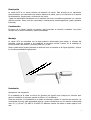
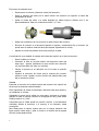
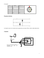
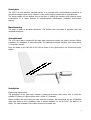
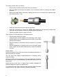
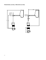
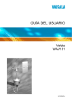
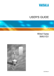
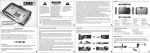
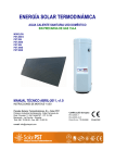
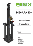
Ornytion VELETA 207P. MANUAL DE USUARIO WIND VANE 207P. USER MANUAL Doc: 1304-2071-01ml 04/2011 2 Descripción La veleta 207P es un sensor eléctrico de dirección de viento. Está provista de un transductor potenciométrico que suministra una tensión eléctrica de salida, que es una fracción de la tensión de alimentación, proporcional a la dirección del viento. Puede ser alimentada únicamente en el momento de hacer la medida presentando un consumo eléctrico mínimo. Posee una alta inmunidad a interferencias electromagnéticas (grado ambiente industrial). Construcción El cuerpo de la veleta, incluido el conector, está construido en aluminio anodizado. Las partes móviles son de acero inoxidable y aluminio anodizado. Montaje La veleta 107A se suministra con la aleta posterior desmontada para reducir el volumen del embalaje. Antes de proceder a su instalación es necesario montar la aleta. En el embalaje se incluye la aleta, dos tornillos y una llave Allen de 1,5 mm. Situar la aleta sobre la parte plana de la varilla tal como se muestra en la figura siguiente y colocar los tornillos apretándolos ligeramente. Instalación Accesorio de sujeción En el embalaje de la veleta se incluye un accesorio de sujeción que incorpora un conector apto para su colocación en tubos de soporte de 25mm (1”) de diámetro. Antes de proceder a la instalación de la veleta es necesario cablear el conector del accesorio. Se recomienda el uso de cable apantallado de tres o cuatro conductores con una sección comprendida entre 0,2 y 0,8 mm2 (24 AWG a 18 AWG). El diámetro exterior del cable no debe superar los 8 mm. 3 El proceso de cableado sera: • Desenroscar el conector (elemento verde) del accesorio. • Pasar el extremo del cable por la parte inferior del accesorio de sujeción a través del pasacables de goma. • Quitar la funda del cable y la malla dejando los cables internos visibles unos 2 cm aproximadamente. Pelar los conductores entre 5 y 7 mm. • Soldar los conductores en los pines por la parte interna del conector. • Enroscar el conector en el accesorio girando el soporte y manteniendo fijo el conector (se puede usar la veleta a modo de llave para apretar ligeramente la rosca). • Apretar el tornillo de plástico de la base para fijar el cable. A continuación se procederá al montaje de la base de sujeción en el tubo de soporte: • Pasar el cable por el tubo. • Introducir el tubo en la parte inferior del accesorio hasta que haga tope. Apretar levemente los dos tornillos del accesorio con una llave Allen de 3mm (no incluida). • Colocar el soporte en su ubicación con la la base en posición vertical. • Orientar el accesorio de forma que la muesca del conector señale el norte. Apretar los dos tornillos de cabeza Allen para fijar el accesorio al tubo. Veleta Presentar el conector de la veleta encima del accesorio de sujeción de forma que las muescas estén alineadas. Girar ligeramente la veleta de izquierda a derecha hasta que asiente y se introduzca en la base. Sujetando el cuerpo de la veleta con una mano, enroscar el conector girando la rosca en sentido contrario a las agujas del reloj (vista desde arriba) hasta oír un “click”. Comprobar que la veleta queda en posición vertical. y correctamente orientada. Ajustar el accesorio y el soporte, si es necesario, hasta conseguirlo. Para desenroscar la veleta, sujetar este por su cuerpo haciendo una ligera presión hacia abajo y girar la rosca en el sentido de las agujas del reloj (vista desde arriba) 4 Conector Pin Función N Cable (opcional) A P1 blanco B señal verde C común marrón D - - E - - F - - G común amarillo F E A G D B C Vista inferior Esquema eléctrico Los ángulos crecen en el sentido de las agujas del reloj (hacia el Este), vista la veleta desde arriba. Conexión Equipo de medida señal +Vin P1 Vref veleta común común malla Para mejor protección del equipo es conveniente que GND esté conectado a tierra GND v -Vin o GND tierra 5 Características Rangos de operación Velocidad del aire Temperatura Tensión de alimentación Ángulo de medida Vida útil < 60 m/s -25 ... +60 ºC 0 ... ±10 V 0 ... 360º > 50 x 106 giros Características dinámicas. Determinadas según el método ASTM D5366-96 Umbral de arranque Factor de amortiguamiento (η) Constante de distancia (D) < 0,6 m/s 0,20 0,6 m Características eléctricas. Valores típicos a 21ºC con 2,5 V DC de alimentación y 10MΩ de carga Señal de salida Función de transferencia Fracción de la tensión eléctrica de alimentación Resistencia del sensor Resolución Error de linealidad Ángulo eléctrico de medida Compatibilidad Electromagnética 10 kΩ ±20% infinita < 1% 357º ± 1º EN 61000-6-2:2006 EN 61326-1:2006 v V º = 360⋅ V REF Dimensiones Peso Altura Diámetro del cuerpo Diámetro de giro 6 0,225 kg 265mm 39,5 mm 322 mm Declaración de Conformidad Ornytion Tr. de San Cidre, 14 15165- Bergondo A Coruña España declaramos bajo nuestra exclusiva responsabilidad la conformidad del producto: Veleta Modelo 207P al que se refiere esta declaración, con las disposiciones de la Directiva: 2004/108/CE sobre Compatibilidad Electromagnética para lo cual se ha seguido la normas armonizadas: EN 61000-6-2:2006 Compatibilidad electromagnética. Inmunidad en entornos industriales. EN 61326-1:2006 Material eléctrico para medida, control y uso en laboratorio. Requisitos de compatibilidad electromagnética. Bergondo, 21 de diciembre de 2010 Pedro Rosende Responsable de I+D 7 8 Description The 207P is a wind direction electrical sensor. It is provided with a potentiometric transducer It provides a voltage output that is a fraction of the power supply, proportional to wind direction. The power supply can be applied only at the time of making the measure with minimal power consumption. It is highly immune to electromagnetic interferences (industrial environment degree). Manufacturing The body is made of anodized aluminium. The mobile parts are made of stainless steel and anodized aluminium. Assemblement The 107A wind vane is issued with the back plate removed to reduce the packing volume. Before installation it is necessary to mount the plate. The packaging includes the plate, two screws and a 1.5 mm Allen wrench. Place the blade on the flat side of the rod as shown in the figure below, set screws and lightly tighten Installation Fastening accessory The packaging of the wind vane includes a fastening accessory that comes with a connector, suitable for placing on support tubes with a 25mm (1'') diameter. Before installing the wind vane you must wire the connector. We recommend the use of shielded cable with three or more conductors with a section between 0.2 and 0.8 mm2 (24 AWG to 18 AWG). The outer diameter of the cable should not exceed 8 mm. 9 The wiring process will be as follows: • Unscrew the connector (green part) from the accessory. • Pass the cable end through the bottom of the accessory and put it through the rubber grommet. • Remove the cable sleeve and mesh, leaving about 20 mm of internal wires exposed. Peel the wires from 5 to 7 mm. • Solder the wires onto the pins inside the connector • Screw the connector by turning the bracket and maintaining the connector upright (the wind vane can be used as a wrench to slightly tighten the screw). • Tighten the plastic screw to secure the wire. Then proceed to fit the accessory in the support tube: • Pass the cable through the tube. • Insert the tube into the bottom of the accessory until it stops. Slightly tighten the two attachment screws with a 3mm Allen wrench (not included). • Place the bracket in its location with the accessory in a vertical position. • Align the attachment so that the notch on the connector points north. Tighten the two Allen head screws to secure the base to the tube. Wind Vane Put the connector of the wind vane above the fastening accessory so that the notches are aligned. Turn the wind vane slightly counterclockwise to clockwise until it snaps into place. Holding the body of the wind vane in one hand, tighten the connector by turning the screw counterclockwise (viewed from above) until you hear a click. Check that the wind vane is vertical and correctly orientated. If necessary adjust the support to achieve this. To unscrew the wind vane, hold the body and with slight downward pressure and turn the screw clockwise (viewed from above) 10 Connector Pin Function Cable (optional) A P1 white B signal green C common brown D - - E - - F - - G common yellow N F E A G D B C Bottom view Electrical Schematic The angles grow in a clockwise direction (eastward), wind vane viewed from above. Application Measurement equipment signal +Vin P1 Vref wind vane common common shield For a better equipment protection, -Vin/GND should be earthed GND v -Vin or GND earth 11 Features Operating range Wind speed Temperature Supply voltage Measurement angle Life < 60 m/s -25 ... +60 ºC 0 ... ±10 V 0 ... 360º > 50 x 106 turns Dynamic Characteristics. In accordance with ASTM D5366-96 Starting threshold Damping ratio (η) Delay distance (D) < 0.6 m/s 0,20 0.6 m Electrical Characteristics. Typical values at 21ºC with 2,5 V DC power supply and 10MΩ load Output signal Transfer function Fraction of supply voltage Sensor resistance Resolution Linearity error Electrical angle Electromagnetic Compatibility 10 kΩ ±20% infinite < 1% 357º ± 1º EN 61000-6-2:2006 EN 61326-1:2006 v V º = 360⋅ V REF Dimensions Weight Heigh Body diameter Turning circle diameter 12 0.225 kg 265mm 39.5 mm 322 mm Declaration of Conformity We, Ornytion Tr. de San Cidre, 14 15165- Bergondo A Coruña Spain declare under our sole responsibility that the product: Wind Vane Model 207P to which this declaration relates, is in conformity with the Directive: 2004/108/CE about Electromagnetic Compatibility and meets the requirements to the following standards: EN 61000-6-2:2006 Electromagnetic compatibility. Immunity for industrial environments. EN 61326-1:2006 Electrical equipment for measurement, control and laboratory use. EMC requirements. Bergondo, December 21, 2010 Pedro Rosende R&D Manager 13 Dimensiones (en mm) / Dimensions (in mm) 14 15 Ornytion 16 Ornytion Tr. San Cidre, 14 15165 Bergondo - España [email protected] www.ornytion.com