1
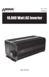
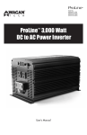
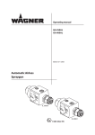
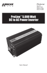
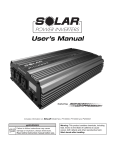
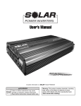
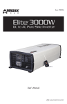
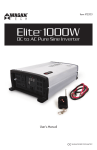
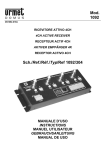
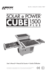
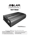
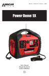
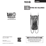
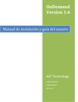
ProLine
™
Item / Artículo # 2007-2
3000 Watt AC Inverter
Inversor de Energía 3000W
User’s Manual
Manual de Usuario
ProLine™ 3000W Power Inverter by Wagan Tech®
Thank you for purchasing the ProLine™ 3000W Power Inverter by Wagan Tech®. With
minimal care and proper treatment it will provide years of reliable service. Carefully
read, understand and comply with all instructions before use. Keep this manual for future
reference.
User’s Manual—Read before using this equipment
This inverter may not properly operate some appliances with either speed control features
or dimmer controls. Some appliance GFCI power cords will not operate properly while
powered by this inverter. The only way to be sure of proper operation is to try it.
Safety Warning: The
ABOUT THE INVERTER
This power inverter converts 12 volts, direct current (12V DC) to 115 volts alternating
household current (115V AC). It easily powers TV, DVD players, microwave ovens,
refrigerators, and small air conditioners. It also operates at the highest efficiency (up to 90%)
that results in longer run times and extended battery life compared to other inverters with
this level of power output.
This inverter has the highest surge capability in its class. Superior surge capability allows the
inverter to start most difficult motorized loads. Advanced circuitry runs cooler and is more
reliable than competing units.
GENERAL INSTRUCTIONS:
inverter output can be lethal . I mproper use of this
inverter may result in property damage, personal injury or loss of life .
FRONT PANEL
The Front Panel contains the inverter’s ON/OFF Switch, Digital Indicators, direct wiring
High Current Terminals, Two AC Outlets and a Remote Switch Connector for connecting an
optional Remote Switch cable.
Digital Display
ON/OFF
Switch
• Keep the inverter away from any direct heat source or combustible materials.
Remote
ON/OFF
Switch
Connection
• Keep well ventilated – this device generates heat.
• Keep the inverter away from combustible fuel or battery gases.
• Do not continuously operate any equipment over 3000 Watts.
Display
Selector
Green LEDs
• This inverter operates from a 12 volt DC power source only.
Two 120V
AC Outlets
• Do not attempt to connect the inverter to any other power source, including
any AC power source.
• Incorrect battery polarity will damage the inverter and void the warranty.
• Keep this inverter in a dry environment.
• Do not open the inverter; there are no user serviceable parts inside.
1
2
3
LOAD CONSIDERATIONS
When an appliance with a motor starts, it requires a momentary surge of power. This surge
of power is the “starting load” or “peak load”. Once started, the appliance requires less
power to continue to operate. This is known as the “continuous load”. It is important to know
starting loads and continuous loads of appliances that will be powered by the inverter.
Appliance power is rated in watts. This information is usually stamped or printed on most
appliances and equipment. In some cases, a tool will be rated in amperes. To convert
from amps to watts, multiply: AMPS × 115 (AC voltage) = WATTS. This formula yields an
approximation of the continuous wattage load of that appliance.
The startup load of an appliance is a major factor of whether this inverter can power it.
Startup load is momentary. With many appliances, it is approximately twice the continuous
load but some appliance startup loads can be as high as eight times the continuous load.
To determine if an appliance or tool will operate with this inverter, run a test. This inverter
is will automatically shut down in the event of an output overload, so there is no danger of
damaging either the inverter or the equipment.
High Output
Terminals
On/Off Switch
This switch turns the inverter on and off.
Digital Display, Function Button, and Green LEDs
The inverter is equipped with a digital display to monitor input DC volts, DC amps, AC output
watts and error codes. A Display Selector button allows the user to advance the display
readout to the next readout. The lit/unlit status of two green LEDs show which function is being
shown on the Digital Display
The display and button are used to help diagnose problems if they occur.
1
www.wagan.com
©2012 Wagan Corporation. All Rights Reserved.
Wagan Tech and wagan.com are trademarks used by Wagan Corporation.
2
ProLine™ 3000W Power Inverter by Wagan Tech®
Green LEDs Status (Shows Display Mode,
LEFT LED
RIGHT LED
= Lit,
= Unlit)
DISPLAY Mode
DC Input Voltage
DC Input Current (Amps)
AC Output Wattage (Kilowatts)
Diagnostic Codes (E01, E02, E03, E04)
Volts Readout – Digital Display (left LED unlit, right LED Lit)
The volts display is the measurement of the voltage at the DC terminals of the inverter, not
actual battery voltage. During high wattage applications the display may show a lower
voltage level than the battery because of a voltage drop that can occur between the DC
input cables and the battery. This voltage drop should not be greater than 0.25 to 0.5 volts,
as a greater voltage will seriously reduce run time. This inverter will operate with input
voltage ranging from 10 to 15 volts of direct current (DC). If the inverter input voltage level
falls to 10.5 volts DC, an audible alarm will sound. When the voltage drops below 10 volts
DC, the inverter will automatically shut down.
During charging from a generator, solar panel or AC powered charger the battery voltage
will be higher than when it is resting. This inverter will automatically shutdown if the input
voltage is 15 volts or higher. Voltages greater than 15 may cause damage to the inverter.
Damage caused by excessive voltage input is not covered under the warranty.
Amps Readout – Digital Display (left LED lit, right LED unlit)
This readout indicates actual DC amperes of current being drawn from the battery bank.
Note that for a 120 amp reading the inverter should be powering 1200 watts of AC load.
Watts Readout – Digital Display (both left LED and right LED lit)
User’s Manual—Read before using this equipment
High Output AC Terminals
There are three insulated terminals on the front panel of the inverter. These terminals are for
connecting 115 volt AC devices that require more than 15 amps to operate. Other uses are
for connection to distributed wiring that has multiple AC outlets. Any wiring that is directly
connected must be 10 gauge or larger. Facing the Front Panel, the terminals are:
Left
Middle
Right
Ground
Neutral
Hot or Live
Neutral and Ground are bonded inside the inverter to comply with the National Electric Code
(NEC) requirement that any AC source must have a Neutral to Ground connection.
Two 115V AC Outlets
Each outlet will supply up to 15 amps 115V AC maximum, for powering appliances. Greater
than 1650 watts continuous power from an outlet may cause damage to the inverter and
cause possible injury. Use the high output terminals for appliance loads greater than 15
amps.
Remote On/OFF Switch Connection
A supplied cable and Remote Switch assembly provides a convenient remote On/Off
feature.
Power Inverter Output Waveform
This inverter’s AC output is a modified sine wave (MSW) 115 volts AC. The comparison of
modified sine wave and household AC is shown in the figure below.
This modified sine wave has a root mean square (RMS) voltage of 115 volts. Most ordinary
AC voltmeters are calibrated to read “average” voltage and assume that the AC waveform
will be a pure sine wave. These meters will not correctly read MSW voltage, and will display
about 20 to 30 volts too low. Any multi-meter identified as “TRUE RMS” will accurately read
MSW correctly.
The Watts readout shows AC watts delivered to the connected operating AC appliance
load.
Diagnostic Error Codes – Digital Display (both left LED and right LED unlit)
When diagnostic codes are selected for display, the user will see four “Error Codes”
designated as E01, E02, E03 and E04. These codes are associated with a reason for
inverter shut down. Their meanings are as follows:
E01 – Overload
E02 – Over Temperature
E03 – Low Battery
E04 – Over Voltage
3
Modified Sine Wave (MSW)
www.wagan.com
Pure Sine Wave
©2012 Wagan Corporation. All Rights Reserved.
Wagan Tech and wagan.com are trademarks used by Wagan Corporation.
4
ProLine™ 3000W Power Inverter by Wagan Tech®
User’s Manual—Read before using this equipment
REAR PANEL
• Battery bank capacity in amp-hours
• Charger requirement to charge batteries within a practical time.
High-Speed
Cooling Fans
• Distance between battery bank and inverter.
DETERMINING MAXIMUM APPLIANCE WATTAGE
Maximum AC appliance wattage is the first factor in planning battery and charging systems.
Some background: Large microwave oven specifications list cooking power (watts) and
appliance power. Appliance power is the AC load the inverter has to supply.
Most other electrical tools, appliances and audio/video equipment have labels that list the
unit’s power requirements in watts. If the tool or device is rated in amps, multiply the amps
by 115 (115V AC) to determine the watts. For example, a power tool rated at 4 amps will
draw 460 watts.
Negative (−) DC
Input Terminal
Positive (+) DC
Input Terminal
Ground
Terminal
Determine the wattage of each appliance you need to simultaneously operate. Add all of
the appliance wattages to obtain an estimated “total watts” number. Remember to consider
the startup surge that motorized appliances will cause. Do not exceed the surge rating of this
inverter (6000 watts). This can cause immediate an overload shutdown.
At 3000 watts continuous output, this inverter requires a DC power supply (battery bank)
that can continuously supply 300 amps at 12V DC for the duration of the run time.
CONFIGURING THE BATTERY BANK
To determine the minimum battery ampere-hour rating that you will need to operate
appliances from the inverter, and any DC appliances powered by the battery bank. Follow
these steps:
1. List the maximum continuous wattage that the inverter has to supply.
High-Speed Cooling Fans
Two high-speed fans keep the internal temperature of the inverter within operating limits.
Negative DC (−) Input and Positive DC (+) Input Terminals
DC input terminals are used to connect the inverter to heavy duty cables from the battery or
battery bank. For connection information, refer to the sections on installation.
Ground Terminal
This connection is located on the lower left of the rear panel. It is for attaching a 6 gauge
insulated safety ground wire. This safety wire is for protecting personnel if there is an
unlikely failure in either the cabling or enclosure insulation. Do not directly connect this
ground connection to the negative DC terminal. This safety wire is to be connected to the
vehicle frame or earth ground. This is described in the installation procedure.
PLANNING THE INVERTER SYSTEM
Any large wattage inverter system requires planning before installation. There are several
steps to the planning process so the user must determine the following:
5
2. Estimate the number of hours the appliances will be in use between battery recharges.
This will vary depending on appliances. For example, a typical home use coffeemaker
draws 500 watts during its brew time of 5 minutes. It maintains the temperature of the
pot, requiring 100 watts. Typical use of a microwave oven is only for a few minutes.
Some longer operating time appliances are lamps, TVs, computers and refrigerator/
freezers.
3. Determine the total watt-hours of energy needed. This is done by multiplying average
power consumption in watts by hours of run time. For example: 1500 watts for 10
hours = 15,000 watt hours.
4. To get an estimate of the maximum current (in amps) that a battery bank must be
capable of delivering to the inverter, divide the load watts by ten. For example a 1500
watt appliance load will need 150 amps at 12 volts DC.
5. Using the 1500 watts (or 150 Amps) for 10 hours example as above, then 150 amps
is needed for 10 hours. This provides us with the basic amp-hours (AH) of battery that
is required. Ten hours at 150 amps equals 1500 amp-hours (AH). This answer is just a
beginning because there are additional factors that determine actual run time. These
include:
• Maximum inverter wattage required
• AC appliance load and time in use (basic AH)
• Operating time (run time) needed between battery recharges
• Cable gauge and length (cable losses)
www.wagan.com
©2012 Wagan Corporation. All Rights Reserved.
Wagan Tech and wagan.com are trademarks used by Wagan Corporation.
6
ProLine™ 3000W Power Inverter by Wagan Tech®
• Charge level of the batteries (between use, chargers have to be able to fully
charge the batteries)
• Temperature of the batteries (colder batteries provide fewer amps)
• Age and condition of the batteries (older batteries lose AH capacity)
• Compliance with turning off unnecessary AC loads.
• Use of DC appliances and compliance with turning off unnecessary
DC loads.
DERATING THE BATTERY BANK
Most lead-acid batteries have a rating expressed in amp-hours (AH). The most common
rating of AH is “at the 20 hour rate”.
NOTE: Despite several Internet explanations, here is no relationship between Cold Cranking
Amps (CCA) and Ampere Hours (AH).
For example; if a 20AH battery is discharged at a 1 amp rate, is will take 20 hours to
discharge that battery. The terms “charged” and “discharged” relate to actual battery
voltage. This means that the output voltage of a nominal 12 volt battery starts at 13.2 volts
(fully charged) then drops to 10.6 volts (discharged). If the load on the battery causes
the battery to discharge faster than the 20 hour rate, the capacity (AH) of the battery is
measurably reduced (derated). Derating is a major run time factor. The curve in the following
chart can help to determine what the battery bank can deliver under load. The results are
used to estimate how much additional battery capacity is needed to achieve the desired run
time.
User’s Manual—Read before using this equipment
means that a higher battery capacity is required to get the desired run time, one hour. The
curve also shows that a load of 200 percent of the 20 hour rate yields only 31 percent of
the battery capacity. The installer must carefully plan the capacity of battery bank or the run
time may be seriously affected. To the inexperienced installer, several trial battery capacities
may be required to make sure the large enough battery capacity is available to achieve the
desired run time.
The curve can be applied to any lead acid battery under load providing that it has an AH
rating at the 20 hour rate.
Continuing with the example above: The 150 amp load will need to run for 10 hours, so we
begin configuration with a 1500 AH battery. If the vertical is 1500 and the horizontal is 150
amps, the percentage of load on the battery is 10 percent. The curve shows that the 1500
AH is derated to 90 % of maximum. This means that the battery will have to be 1650 AH for
the full 10 hour run time. It is important to add some extra battery capacity, because as the
batteries age, they will lose AH capacity.
CONFIGURATING THE BATTERY BANK
Six volt, 220 AH “golf cart” batteries were selected for these illustrations because they are
generally readily available and relatively inexpensive. They are deep-cycle type and with
regular recharging they have a relatively long life. These batteries are “flooded” type; they
freely vent hydrogen and oxygen while under charging and heavy discharge. They must be
vented to outside air to prevent accumulation of explosive gases.
BATTERY BANK DIAGRAM
The diagram below shows inverter connections to a battery bank with recommended fuse
protection.
Fuse
+
6V
220Ah
INVERTER
6V
220Ah
+
6V
220Ah
–
–
–
+
+
+
6V
220Ah
Safety Ground
+
–
6V
220Ah
6V
220Ah
–
–
The left vertical numbers of the curve represents percentage of the battery capacity at the
20 hour rate. In this example, the user needs a one hour run time. If the example battery is
220AH (20 hour rate), and the load is 220 amps that is 100 percent (horizontal number)
of the AH (20 hour rate). Starting at the 100 percent horizontal point and looking up to
the curve the results are that only 56 the percent of the battery capacity is available. This
7
www.wagan.com
©2012 Wagan Corporation. All Rights Reserved.
Wagan Tech and wagan.com are trademarks used by Wagan Corporation.
8
ProLine™ 3000W Power Inverter by Wagan Tech®
FUSING REQUIREMENTS
NOTE: It is important that this 3000 watt inverter has one ANL 400 ampere or equivalent
main battery fuse added to the Positive (+) battery cable as close as possible to the battery
bank’s positive terminal. The fuse amperage rating must be sized to allow simultaneous
operation of all the AC appliances to be powered, allowing for the momentary high startup
current requirements of inductive loads. Use the recommended fuse block (fuse holder) and
fuse, or an electrical equivalent. ANL type fuses and fuse holders are readily available from
marine supply dealers.
The 400 amp battery protection fuses is very important to protect equipment, batteries
and personnel. The fuses protect against battery explosion if the cables that connect to the
inverter accidentally short.
WARNING!
E xploding
batteries can spray molten lead, hot sulfuric acid and other metal and plastic
fragments .
Batteries
that are charging or under high discharge rates produce explosive
hydrogen gas into the surrounding area .
the batteries are properly ventilated.
Be
safe—fuse the battery bank and make sure
4. Locate the Ground Lug Terminal at the rear of the inverter. Connect an insulated 6
gauge copper wire to the terminal. The other end of the ground wire is connected to
a “proper” grounding point. Use the shortest practical length of wire. Connect this
wire to the chassis of your vehicle or to the grounding system in your boat. In a city,
the ground wire can connect to a metal cold water pipe that goes underground. In
remote locations, the ground wire can be connected to an “earth ground”. This can be
an attachment to a 6 foot long copper clad metal rod driven into the ground. In the
unlikely event of a short circuit, operating the inverter without proper grounding can
result in electrical shock. Do not directly connect this ground wire to the Negative DC
Terminal. You can connect the ground wire to the negative battery terminal.
NOTE: The cable ends need to be stripped of insulation for approximately ¾ of an inch
at both ends. The battery ends or fuse end needs to have ring terminals crimped onto
the bare cable ends.
5. Use a socket wrench to loosen and remove the Positive (+) and Negative (−) cable
connector retaining nuts. Place the Negative (−) cable ring terminal onto the Negative
(−) DC terminal. Place the retaining nut on the terminal stud. Use the socket wrench to
make a good, secure connection.
6. Recheck and make sure the DC cable fuse is installed in the fuse holder.
7. Attach the Positive (+) DC cable to the Positive (+) terminal on the battery. Avoid
shorting the socket wrench and carefully tighten the retaining nut.
DC Cable Gauge
Minimize cable losses by using the thickest wire available, and the shortest practical length.
If the inverter and the battery are positioned within four feet of each other, a minimum of 0
gauge (zero gauge) insulated copper wire should be used to make the connections. If the
round trip distance is longer than 4 feet, heavier wire will be required.
CONNECTING THE INVERTER
General information
Loose connections will result in a severe voltage drop that can cause damage to connectors,
conductors, and insulation and can cause sparking. Make sure all cables are the proper
gauge and plan to have the ANL fuse holder within one foot of the battery bank’s Positive
(+) terminal. All cable ends need to be stripped of insulation for approximately ¾ of an inch
to have appropriate sized ring terminals crimped onto the bare cable ends. Appropriately
sized socket wrenches should be used to carefully tighten the retaining nuts on the terminals
of the battery bank, fuse holder and DC terminals on the back panel of the inverter.
CAUTION: Reverse polarity connection will blow the fuses in the inverter and can
permanently damage the inverter. Damage caused by reversed polarity will void the
warranty.
Procedure
9
User’s Manual—Read before using this equipment
CAUTION: Making an initial connection between the positive cable and the inverter’s
positive terminal may cause a spark. This is a normal and is a result of capacitors in
the inverter starting to charge. Because of the possibility of sparking, it is extremely
important that both the inverter and the battery bank be positioned away from any
source of flammable fumes or gases. Failure to heed this warning can result in fire
or explosion. Do not make the positive terminal connection immediately after the
batteries have been charging. Allow time for the battery gasses to vent to outside air.
8. Attach the positive cable ring terminal to the Positive (+) DC connector stud on the
inverter. Replace the retaining nut and carefully tighten. Make sure the connection is
tight and secure.
9. Turn on the inverter. Advance the Digital Display to the Voltage display (right green
LED lit) by pressing the FUNCTION button. The display on the front panel should
show 10.5 to 13.2 volts depending on the voltage of the power source. When the
voltage reading does not fall within this range, check the connections of the wires to
the terminals on the battery bank and the inverter to make sure they are secure. Also
check the voltage of the power source. Advance the Digital Display to the Diagnostic
Error Codes (green LEDs not lit). Look for code E03: Low Voltage Shutdown. If this
code is present, then check for loose connections of discharge batteries.
10.Turn off the inverter. The audible alarm may sound a short “chirp”. This is also normal.
1. Connect the Negative (−) cable ring terminal to the Negative (−) Battery Terminal.
11.When you have confirmed that the appliance to be operated is turned off, plug the
appliance into one of the two AC outlets on the front panel of the inverter.
2. Install the ANL fuse in the Fuse holder Positive (+) cable.
12.Turn the inverter on.
3. Make sure the ON/OFF switch located on the front panel of the inverter is in the OFF
position. Disconnect any remote switch from the connector on the front panel.
13.Turn the appliance on.
www.wagan.com
14.The Remote On/Off switch should be placed in a location convenient to the user.
Insert the cable plug into the front panel connector. The inverter’s Front Panel On/Off
©2012 Wagan Corporation. All Rights Reserved.
Wagan Tech and wagan.com are trademarks used by Wagan Corporation.
10
ProLine™ 3000W Power Inverter by Wagan Tech®
Switch must be On for the Remote Switch to operate. A lit LED indicator on the Remote
Switch indicates when DC power is applied to the inverter. Pressing the momentary
button controls On/Off operation of the inverter.
Note: If an extension cord is used from the inverter to the appliance, limit the extension
cord length to 50 feet or less. Make sure that the cord is properly rated to carry the
appliance load.
CHARGING THE BATTERY BANK
It is not the purpose of this Inverter User’s Guide to provide detailed information regarding
battery charging systems. However, the user should try to augment any charging system with
either wind power or solar power. These can continue to operate during power outages and
they also reduce recharge time. If automatic AC powered battery chargers do not provide
enough charging current for a larger battery bank, is permissible to have two automatic
battery chargers connected to the battery bank.
REGULAR LOSS OF COMMERCIAL POWER
If the inverter system is used during commercial power outages that occur daily, configure
the charger system to replace energy during the time that commercial power is available.
Replacement of battery energy always requires more than was taken from the battery
(typically 130 percent). In the example used earlier in this document, the AC load ran for 10
hours. If commercial power is available, there are approximately 14 hours left in the day to
do the recharging. The following is an example of what is necessary to recharge a battery
bank that has 1650 AH of capacity (as in the example above) and has been discharged to
10.5 volts (discharged). The charger has to replace 2145 AH (1650 x 1.3 AH) in 14 hours,
so the charger must charge at a rate of 153 amps for 14 hours. As this charge current is
distributed among the batteries in the battery bank, the current received by an individual
battery is within its charge rating. Be sure that the battery is well vented as the area will
likely have accumulations of an explosive mixture of hydrogen and oxygen. Follow all
recommendations for use that are contained in the battery charger manual.
User’s Manual—Read before using this equipment
ABOARD A VESSEL OR VEHICLE.
Manufacturer supplied engine driven alternators can usually be replaced with one that can
continuously deliver higher amperage. This should be done at the outset. Keep the batteries
charging when the vessel or vehicle engine is operating. In the case of a vessel, make sure
that shore power is used to recharge the batteries whenever possible.
OPERATING ISSUES
Television and Audio Suggestions
Although all inverters are shielded and filtered to minimize signal interference, some
interference with your television picture may be unavoidable, especially with weak signals.
However, here are some suggestions that may improve reception.
• First, make sure that the television antenna produces a clear signal under normal
operating conditions (i.e. at home plugged into a standard 11O/120V AC wall outlet).
Also ensure that the antenna cable is properly shielded and of good quality.
• Change the positions of the inverter, antenna cables and television power cord.
• Isolate the television, its power cord and antenna cables from the 12 volt power
source by running an extension cord from the inverter to the television set.
• Coil the television power cord or install a clamp-on ferrite choke (available from
electronic parts suppliers).
Note: Some inexpensive audio systems may have a slight “buzzing” sound when operated
with the inverter. This is caused by insufficient filtering in the audio system. The only solution
to this problem is to get a sound system with a higher quality power supply.
WARNING
THERE IS DANGER OF AN EXPLOSION. DO NOT CONNECT OR DISCONNECT
CHARGER CABLES DIRECTLY AFTER BATTERY DISCHARGE OR RECHARGE
— MAKE SURE THAT THE BATTERY BANK AREA IS WELL VENTED BEFORE
ATTACHING OR REMOVING CABLES.
If flooded lead acid batteries are used, as examples given in this document, be sure that
periodic checks of battery electrolyte levels are done. Follow battery manufacturer’s
instructions in keeping the electrolytes at the proper level. Be sure to use pure distilled water
when replacing evaporated electrolyte liquid.
11
www.wagan.com
©2012 Wagan Corporation. All Rights Reserved.
Wagan Tech and wagan.com are trademarks used by Wagan Corporation.
12
ProLine™ 3000W Power Inverter by Wagan Tech®
TROUBLESHOOTING
User’s Manual—Read before using this equipment
SPECIFICATIONS
PROBLEM: Low or no output voltage
Reason
Solution
Poor contact with battery terminals.
Clean terminals thoroughly.
Using incorrect type of voltmeter to test
output voltage.
Use true RMS reading meter.
PROBLEM: Inverter shutdown
Name
Description
Input
12V (10–15V) DC
Output
120V AC ± 10%
Frequency
60 Hz
Output Waveform
Modified Sine Waveform
Continuous Power
3000 watts
Surge Power
6000 watts
Approximately 90%
Reason
Solution
Efficiency
Battery voltage below 10 volts. (Code E03)
Recharge or replace battery.
No load
Equipment being operated draws too much
power. (Codes E01 or E02 or E03)
Use a higher capacity inverter or do not use
this equipment.
Inverter is too hot: thermal shutdown. (Code
E02)
Allow inverter to cool.
Low Battery Alarm
10.5 ± 0.5V DC
Check for adequate ventilation.
Low Battery Shutdown
10 ± 0.5V DC
Reduce the load on the inverter to rated
continuous power output.
Over Temp Shutdown
140ºF ± 9ºF (60ºC ± 5ºC)
AC output sockets
2 US standard
Power switch
DC input ON/OFF control
Dimensions (L × W × H)
12.8 × 7.2 × 6.8 inches (325 × 182 × 173 mm)
Net Weight
11.7 lbs (5.3 Kg) approximately
Unit may be defective.
See warranty and call customer service.
PROBLEM: TV interference
Reason
Solution
Electrical interference from the inverter.
Add a ferrite data line filter on to the TV
power cord.
PROBLEM: Low battery alarm on all the time (Code E03)
Reason
Solution
Input voltage below 10.5 volts.
Keep input voltage above 10.5 volts to
maintain regulation.
Poor or weak battery condition.
Recharge or replace battery.
Inadequate power being delivered to the
inverter or excessive voltage drop.
Use lower gauge wire.
Switch ON
<3.0A DC
Switch OFF
<0.2mA DC
NOTE
All specifications are typical at nominal line, half load, and 77ºF (25°C) unless otherwise
noted. Specifications are subject to change without notice.
DISPOSAL OF INVERTER
Electronic products are known to contain materials that are toxic if improperly disposed.
Contact local authorities for disposal and recycling information.
Keep wire length as short as possible.
PROBLEM: TV does not work
13
Reason
Solution
TV does not turn on.
Contact TV manufacture to see if the TV is
compatible with a modified sine wave.
www.wagan.com
©2012 Wagan Corporation. All Rights Reserved.
Wagan Tech and wagan.com are trademarks used by Wagan Corporation.
14
WAGAN Corp. Limited Warranty
The WAGAN Corp. warranty is limited to products sold only in the United
States.
All Wagan Tech products must be registered within (30) days of purchase to
activate its warranty. To register your product, please visit http://tinyurl.com/
waganwarranty. Be sure to keep the original receipt as it will be required
when returning a product under the warranty.
Warranty Duration: This product is warranted to the original purchaser for a
period of one (1) year from the original purchase date, to be free of defects in
material and workmanship. WAGAN Corporation disclaims any liability for
consequential damages. In no event will WAGAN Corporation be responsible
for any amount of damages beyond the amount paid for the product at retail.
Warranty Performance: During the above one (1) year warranty period, a
product with a defect will be replaced with a comparable model when the
product is returned to WAGAN Corporation with an original store receipt. The
replacement product will be in warranty for the balance of the original one (1)
year warranty period.
To return a defective item, please contact WAGAN Corporation at (800)
231-5806 to obtain a Returned Merchandise Authorization number (RMA#),
and return instructions. Each item returned will require a separate RMA#.
After you have received the RMA# and the return instructions from WAGAN
Corporation, please follow the instructions and send the item with PREPAID
SHIPPING, along with all of the required documentation, a complete
explanation of the problem, your name, address and daytime phone number.
WAGAN Corporation will, at its option, replace or repair the defective part.
A Returned Merchandise Authorization number (RMA#) is REQUIRED when
sending in any defective item. WAGAN Corporation is not responsible for any
item(s) returned without an official Returned Merchandise Authorization number.
The item(s) must be returned with prepaid shipping. WAGAN Corporation is
not responsible for any shipping charges incurred in returning the item(s) back
to the company for repair or replacement. This warranty is void if the product
has been damaged by accident, in shipment, unreasonable use, misuse,
neglect, improper service, commercial use, repairs by unauthorized personnel
or other causes not arising out of defects in materials or workmanship. This
warranty does not extend to any units which have been used in violation of
written instructions furnished.
Warranty Disclaimers: This warranty is in lieu of all warranties expressed or
implied and no representative or person is authorized to assume any other
liability in connection with the sale of our products. There shall be no claims
for defects or failure of performance or product failure under any theory of
tort, contract or commercial law including, but not limited to negligence, gross
negligence, strict liability, breach of warranty and breach of contract.
©2008 WAGAN Corp. REV2012
ProLine™ 3000W Inversor de Energía de Wagan Tech®
Gracias por adquirir este inversor de energía de 3000 vatios CC a CA ProLine™ de Wagan
Tech®. Con unos cuidados mínimos y un tratamiento adecuado le ofrecerá años de servicio
fiable. Lea atentamente, comprenda y cumpla con todas las instrucciones antes del uso.
Conserve este manual como referencia en el futuro.
ACERCA DEL INVERSOR
Este inversor de energía convierte 12 voltios de corriente continua (12V CC) en 115 voltios
de corriente alterna doméstica (115V CA). Alimenta fácilmente combinaciones de TV/VCR,
hornos microondas, frigoríficos y pequeños aires acondicionados. También funciona con
la máxima eficiencia (hasta el 90%), lo que permite un tiempo mayor de funcionamiento y
una vida útil de la batería más larga, en comparación con otros inversores con este nivel de
transmisión energética.
Este inversor tiene la mayor capacidad de subida de su categoría. La mayor capacidad
de subida permite al inversor arrancar la mayoría de cargas motorizadas difíciles. Los
avanzados circuitos son más fríos y fiables que en las unidades de la competencia.
INSTRUCCIONES GENERALES:
• Mantenga el inversor alejado de fuentes de calor directo o materiales combustibles.
• Manténgalo bien ventilado - este dispositivo genera calor.
• Mantenga el inversor lejos de combustibles o gases de baterías.
• No use de forma continua equipos de más de 3000 vatios.
• Este inversor funciona exclusivamente con una fuente de alimentación de 12 voltios
CC.
• No intente conectar el inversor a otras fuentes de alimentación, incluyendo
Manual de Usuario—Leer antes de utilizar este equipo
CONSIDERACIONES DE CARGA
Cuando arranca el motor de un electrodoméstico, precisa de una subida momentánea de
energía. Esta subida de energía es la “carga inicial” o “carga pico”. Una vez arrancado,
el electrodoméstico precisa de menos energía para continuar funcionando. Ésta se conoce
como “carga continua”. Es importante conocer las cargas iniciales y continuas de los
aparatos que vayan a alimentarse con el inversor.
La potencia del aparato se define en vatios. Esta información está normalmente impresa o
grabada en la mayoría de electrodomésticos y equipos. En algunos casos, una herramienta
puede indicarse en amperios. Para convertir los amperios en vatios, multiplique: AMPERIOS
x 115 (tensión CA) = VATIOS. Esta fórmula proporciona una aproximación a la carga de
vatios continua del aparato.
La carga de arranque de un aparato es un factor importante para saber si este inversor
puede alimentarlo. La carga de arranque es momentánea. En muchos aparatos, es
aproximadamente el doble de la carga continua, pero algunas cargas de arranque de
aparatos pueden ser de hasta ocho veces la carga continua. Para determinar si un aparato
o herramienta funcionará con este inversor, haga una prueba. Este inversor se apagará
automáticamente en caso de sobrecarga de salida, por lo que no corre peligro de dañar ni
el inversor ni el equipo.
Este inversor puede no alimentar correctamente algunos aparatos con funciones de
control de velocidad o controles de regulación. Algunos cables de alimentación GFCI de
aparatos no funcionarán correctamente si se alimentan con este inversor. La única forma de
asegurarse de un correcto funcionamiento es probándolo.
A dvertencia
de seguridad: la energía del inversor puede ser mortal .
Un
uso inadecuado
de este inversor puede provocar daños materials, daños personales o la muerte .
• cualquier fuente de alimentación CA.
• Una polaridad incorrecta de la batería dañará el inversor y anulará la garantía.
• Mantenga el inversor en un entorno seco.
• No abra el inversor; no hay piezas reparables por el usuario en su interior.
17
www.wagan.com
© Corporación Wagan 2012. Todos los derechos reservados.
Wagan Tech y wagan.com son marcas registradas de la Corporación Wagan.
18
ProLine™ 3000W Inversor de Energía de Wagan Tech®
Manual de Usuario—Leer antes de utilizar este equipo
PANEL DELANTERO
El panel delantero contiene el interruptor de encendido/apagado del inversor, los
indicadores digitales, los terminales de alta corriente del cableado continuo, dos salidas
CA y un conector de interruptor remoto para conectar un cable de conmutador remoto
opcional.
Pantalla digital
Interruptor de
encendido/
apagado
Estado de LED verdes
(Muestra el modo de pantalla,
LED IZQUIERDO
LED DERECHO
= Apagado)
Modo PANTALLA
Tensión de entrada CC
Corriente de entrada CC (amperios)
Selector de
pantalla
Vatios de salida CA (Kilovatios)
Códigos de diagnóstico (E01, E02, E03, E04)
Conexión de
interruptor de
encendido/
apagado
remoto
LED verdes
Dos salidas
de 120V
CA
1
2
3
Lectura de voltios – Pantalla digital
(LED izquierdo apagado, LED derecho encendido)
La indicación de voltios es la medición de la tensión en los terminales CC del inversor, no
la tensión real de la batería. Durante aplicaciones de elevados vatios, la pantalla puede
mostrar un nivel de voltaje menor que la batería debido a una caída de tensión que puede
producirse entre los cables de entrada CC y la batería. Esta caída de voltaje no debería
superar entre 0.25 y 0.5 voltios, ya que una tensión mayor reducirá significativamente el
tiempo de funcionamiento. Este inversor funciona con tensiones de entrada entre 10 y 15
voltios de corriente continua (CC). Si la tensión de entrada del inversor cae a 10.5 voltios
CC, se emitirá una alarma acústica. Cuando la tensión caiga por debajo de 10 voltios CC,
el inversor se apagará automáticamente.
Durante la carga por un generador, panel solar o cargador con alimentación CA, la tensión
de la batería será mayor que en reposo. Este inversor se apagará automáticamente si la
tensión de entrada es de 15 voltios o superior. Las tensiones superiores a 15V pueden dañar
el inversor. Los daños causados por una tensión de entrada excesiva no están cubiertos por
la garantía.
Terminales de
alta emisión
INTERRUPTOR DE ENCENDIDO/APAGADO
Este interruptor enciende y apaga el inversor.
Pantalla Digital, Botón de Función Y LED Verdes
El inversor está equipado con una pantalla digital para monitorear los voltios CC de
entrada, los amperios CC, los vatios de salida CA y los códigos de error. El botón
selector de pantalla permite al usuario cambiar la indicación de la pantalla a la siguiente
información. El estado encendido/apagado de dos LED verdes muestra la función que se
está mostrando en la pantalla digital.
La pantalla y el botón se usan para ayudar a diagnosticar problemas si se producen.
Lectura de amperios – Pantalla Digital
(LED izquierdo encendido, LED derecho apagado)
Esta lectura indica los amperios CC reales de la corriente absorbida del banco de baterías.
Observe que para una lectura de 120 amperios el inversor debe estar alimentando 1200
vatios de carga CA.
Lectura de vatios – Pantalla Digital (LED izquierdo y derecho encendidos)
La lectura de vatios muestra los vatios CA aportados a la carga del aparato CA en
funcionamiento conectado.
Códigos de error de diagnóstico – Pantalla Digital
(LED izquierdo y derecho apagados)
Cuando seleccione la indicación de códigos de diagnóstico, el usuario verá cuatro
“Códigos de error”, designados E01, E02, E03 y E04. Estos códigos están asociados al
motivo del apagado del inversor. Su significado es el siguiente:
E01 – Sobrecarga
E02 - Exceso de temperatura
19
= Encendido,
www.wagan.com
E03 – Batería baja
E04 – Exceso de tensión
© Corporación Wagan 2012. Todos los derechos reservados.
Wagan Tech y wagan.com son marcas registradas de la Corporación Wagan.
20
ProLine™ 3000W Inversor de Energía de Wagan Tech®
Manual de Usuario—Leer antes de utilizar este equipo
PANEL TRASERO
Terminales CA de alta emisión
Dispone de tres terminales aislados en el panel delantero del inversor. Estos terminales
sirven para conectar dispositivos CA de 115 voltios que precisen de más de 15 amperios
para funcionar. Otros usos son la conexión de cableado distribuido que tenga múltiples
tomas CA. Cualquier cableado conectado directamente debe ser de galga 10 o mayor.
Mirando al panel delantero, los terminales son:
Izquierdo
Central
Derecho
Tierra
Neutro
Activo
El neutro y el de tierra están vinculados dentro del inversor para cumplir con el requisito
del Código Eléctrico Nacional (NEC), según el cual cualquier fuente CA debe tener una
conexión de neutro a tierra.
Ventiladores de
alta velocidad
Terminal de
entrada CC
negativo (-)
Dos salidas de 115V CA
Cada salida proporcionará hasta 15 amperios de 115V CA como máximo, para alimentar
electrodomésticos. Una alimentación continua superior a 1650 vatios de una toma puede
dañar el inversor y causar posibles heridas. Use los terminales de alta emisión para cargas
de aparatos superiores a 15 amperios.
Terminal de
entrada CC
positivo (+)
Terminal
de tierra
Conexión de interruptor de encendido/apagado remoto
Un cable y grupo de interruptor remoto incluido proporciona una práctica función de
encendido/apagado remota.
Forma de onda de salida del inversor de energia
La salida CA de este inversor es una onda sinusoidal modificada (MSW) de 115 voltios
CA. La comparación de la onda sinusoidal modificada y la CA doméstica se muestra en la
imagen siguiente.
Esta onda sinusoidal modificada tiene una tensión de raíz cuadrada media (RMS) de 115
voltios. La mayoría de voltímetros CA habituales están calibrados para leer la tensión
“media” y asumen que la forma de onda CA será una onda sinusoidal pura. Estos
medidores no leerán correctamente la tensión MSW, y mostrarán aproximadamente entre
20 y 30 voltios menos. Cualquier multímetro identificado como “RMS AUTÉNTICO” leerá
correctamente y con precisión la MSW.
Ventiladores de alta velocidad
Dos ventiladores de alta velocidad mantienen la temperatura interna del inversor dentro de
los límites operativos.
Terminales de entrada CC negativo (-) y CC positivo (+)
Los terminales de entrada CC se usan para conectar el inversor a cables de alto rendimiento
desde la batería o el banco de baterías. Para obtener información sobre la conexión,
consulte las secciones de instalación.
TERMINAL DE TIERRA
Esta conexión se encuentra en la parte inferior izquierda del panel trasero. Sirve para
conectar un cable de tierra de seguridad aislado de galga 6. Este cable de seguridad
sirve para proteger a personas si se produce un fallo en el cableado o el aislamiento del
chasis. No conecte directamente la conexión de tierra al terminal CC negativo. Este cable
de seguridad debe conectarse al chasis del vehículo o a toma de tierra. Se describe en el
procedimiento de instalación.
Onda Sinusoidal Modificada (MSW)
21
www.wagan.com
Onda Sinusoidal Pura
© Corporación Wagan 2012. Todos los derechos reservados.
Wagan Tech y wagan.com son marcas registradas de la Corporación Wagan.
22
ProLine™ 3000W Inversor de Energía de Wagan Tech®
PLANIFICACIÓN DEL SISTEMA INVERSOR
Cualquier sistema inversor de elevados vatios precisa de planificación antes de instalarlo.
El proceso de planificación se compone de diversos pasos, por lo que el usuario debe
determinar lo siguiente:
• Vatios máximos del inversor necesarios.
• Tiempo de funcionamiento necesario entre recargas de baterías.
• Capacidad del banco de baterías en amperios-horas.
• Requisitos del cargador para cargar las baterías en un tiempo práctico.
• Distancia entre el banco de baterías y el inversor.
DETERMINAR LOS VATIOS MÁXIMOS EN EQUIPOS
Los vatios máximos CA del aparato son el primer factor para planificar sistemas de baterías
y carga.
Información de trasfondo: Las especificaciones de hornos microondas grandes indican la
potencia de cocción (vatios) y la potencia del aparato. La potencia del aparato es la carga
CA que debe proporcionar el inversor.
La mayoría de las demás herramientas eléctricas, electrodomésticos y equipos audiovisuales
tienen etiquetas que indican los requisitos de alimentación de la unidad en vatios. Si la
herramienta o dispositivo se indica en amperios, multiplique los amperios por 115 (115V
CA) para determinar los vatios. Por ejemplo, una herramienta indicada en 4 amperios
absorberá 460 vatios.
Determine los vatios de cada aparato que deba usar simultáneamente. Sume los vatios de
todos los aparatos para obtener una estimación numérica de "vatios totales". Recuerde tener
en cuenta la subida de arranque que causarán los aparatos motorizados. No exceda la
clasificación de subida del inversor (6000 vatios). Puede causar un apagado inmediato por
sobrecarga.
Con salida continua de 3000 vatios, este inversor precisa de una alimentación CC (banco
de baterías) que pueda proporcionar continuamente 300 amperios a 12V CC durante todo
el tiempo de funcionamiento.
CONFIGURAR EL BANCO DE BATERÍAS
Para determinar la clasificación de amperios-horas mínima de la batería necesaria para
usar aparato con el inversor, y cualquier aparato CC alimentado por el banco de baterías,
siga estos pasos:
1. Liste los vatios continuos máximos que debe alimentar el inversor.
2. Calcule el número de horas que usarán los aparatos entre recargas de baterías.
Variará según los aparatos. Por ejemplo, una cafetera doméstica habitual absorbe
500 vatios durante su tiempo de preparación de 5 minutos. Mantiene la temperatura
de la jarra, lo que precisa de 100 vatios. El uso normal de un horno microondas es de
solamente unos minutos. Algunos aparatos que funcionan más tiempo son lámparas,
TV, ordenadores y frigoríficos/congeladores.
23
www.wagan.com
Manual de Usuario—Leer antes de utilizar este equipo
3. Determine los vatios-horas de energía necesarios en total. Hágalo multiplicando el
consumo medio de energía en vatios por las horas de funcionamiento. Por ejemplo:
1500 vatios durante 10 horas = 15000 vatios horas.
4. Para obtener el cálculo de la corriente máxima (en amperios) que debe poder
proporcionar un banco de baterías al inversor, divida la carga en vatios por diez. Por
ejemplo, una carga en aparatos de 1500 vatios necesitará 150 amperios a 12 voltios
CC.
5. Usando los 1500 vatios (o 150 amperios) durante 10 horas como en el ejemplo,
anterior, se necesitan 150 amperios durante 10 horas. Esto nos proporciona los
amperios-horas (AH) básicos de batería necesarios. Diez horas a 150 amperios
equivalen a 1500 amperios-horas (AH). Esta respuesta es solamente el comienzo,
porque hay factores adicionales que determinan el tiempo de funcionamiento real.
Incluyen:
• Carga de aparatos CA y tiempo de uso (AH básicos).
• Galga y longitud de cable (pérdidas de cable)
• Nivel de carga de las baterías (entre usos, los cargadores deben poder cargar
por completo las baterías)
• Temperatura de las baterías (las baterías más frías proporcionan menos
amperios)
• Edad y estado de las baterías (las baterías más viejas pierden capacidad de
AH)
• Apagar las cargas CA innecesarias.
• Uso de aparatos CC y apagado de cargas CC innecesarias.
REDUCCIÓN DEL BANCO DE BATERÍAS
La mayoría de baterías de plomo-ácido tienen una clasificación expresada en amperioshoras (AH). La clasificación más habitual de AH es “a ritmo de 20 horas".
NOTA: Pese a diversas explicaciones en Internet, no existe relación entre los amperios de
arranque en frío (CCA) y los amperios horas (AH).
Por ejemplo, si una batería 20AH se descarga aun ritmo de 1 amperio, tardará 20 horas
en descargarse. Los términos “cargado” y “descargado” se refieren a la tensión real de
la batería. Esto implica que la tensión de salida de una batería con 12 voltios nominales
comienza a 13.2 voltios (totalmente cargada) y cae hasta 10.6 voltios (descargada). Si la
carga de la batería hace que se descargue con mayor rapidez que el ritmo de 20 horas,
la capacidad (AH) de la batería se reduce de forma detectable (reducida). La reducción es
un factor importante del tiempo de funcionamiento. La curva de la tabla siguiente puede
ayudar a determinar lo que puede entregar el banco de baterías con carga. Los resultados
se usan para estimar la capacidad de batería adicional necesaria para obtener el tiempo
de funcionamiento deseado.
© Corporación Wagan 2012. Todos los derechos reservados.
Wagan Tech y wagan.com son marcas registradas de la Corporación Wagan.
24
ProLine™ 3000W Inversor de Energía de Wagan Tech®
Manual de Usuario—Leer antes de utilizar este equipo
oxígeno durante la carga y con descarga importante. Deben ventilarse al aire libre para
evitar la acumulación de gases explosivos.
DIAGRAMA DEL BANCO DE BATERÍA
El diagrama siguiente muestra las conexiones del inversor a un banco de baterías con la
protección por fusibles recomendada.
Fusible
+
6V
220Ah
Inversor
Los números verticales de la izquierda de la curva representan el porcentaje de capacidad
de batería con el ritmo de 20 horas. En este ejemplo, el usuario necesita un tiempo de
funcionamiento de una hora. Si la batería de ejemplo es de 220 AH (ritmo de 20 horas), y
la carga es de 220 amperios, es decir, el 100 por ciento (número horizontal) del AH (ritmo
de 20 horas). Comenzando en el punto horizontal del 100 por ciento y ascendiendo a la
curva el resultado es que solamente está disponible el 56 por ciento de la capacidad de
la batería. Por lo tanto, es necesaria una capacidad de batería superior para obtener el
tiempo de funcionamiento deseado de una hora. La curva también muestra que una carga
del 200 por ciento del ritmo de 20 horas proporciona solamente el 31 por ciento de la
capacidad de batería. El instalador debe planificar cuidadosamente la capacidad del
banco de baterías o el tiempo de funcionamiento puede verse gravemente afectado. Para
un instalador sin experiencia, puede ser necesario usar distintas capacidades de baterías
de prueba para asegurarse que se disponga de una capacidad de batería suficiente para
obtener el tiempo de funcionamiento deseado.
La curva puede aplicarse a cualquier batería de plomo-ácido con carga siempre que tenga
una clasificación AH con ritmo de 20 horas.
Siguiendo con el ejemplo anterior: La carga de 150 amperios deberá funcionar durante
10 horas, por lo comenzamos la configuración con una batería de 1500 AH. Si la vertical
es 1500 y la horizontal es 150 amperios, el porcentaje de carga en la batería es del 10
por ciento. La curva muestra que los 1500 AH se reducen al 90% del máximo. Esto implica
que la batería deberá ser de 1650 AH para las 10 horas de tiempo de funcionamiento. Es
importante añadir cierta capacidad de batería adicional, porque a medida que las baterías
envejecen pierden capacidad AH.
CONFIGURAR EL BANCO DE BATERÍAS
Se han seleccionado baterías de seis voltios, 220 AH “de carrito de golf” para estas
ilustraciones porque normalmente están fácilmente disponibles y son relativamente
asequibles. Son de tipo de ciclo profundo y con recarga regular tienen una vida útil
relativamente larga. Estas baterías son de tipo “inundado”; emiten libremente hidrógeno y
25
www.wagan.com
6V
220Ah
+
6V
220Ah
–
–
–
+
+
+
6V
220Ah
Toma de tierra
de seguridad
+
–
6V
220Ah
–
6V
220Ah
–
REQUISITOS DE FUSIBLES
NOTA: Es importante que este inversor de 3000 vatios tenga un fusible de batería principal
ANL de 400 amperios o equivalente añadido al cable de batería positivo (+) tan cerca
como sea posible del terminal positivo del banco de baterías. La clasificación del amperaje
del fusible debe medirse para permitir el uso simultáneo de todos los aparatos CA que
se vayan a alimentar, permitiendo los requisitos momentáneos elevados de corriente de
arranque de cargas inductivas. Use el bloque de fusibles recomendado (soporte de fusible)
y un fusible, o un equivalente eléctrico. Los fusibles de tipo ANL y los soportes de fusible
están disponibles en comercios de material marino.
El fusible de protección de baterías de 400 amperios es muy importante para proteger el
equipo, las baterías y a personas. Los fusibles protegen contra explosiones de las baterías si
los cables que conectan con el inversor se cortocircuitan accidentalmente.
ATENCIÓN
LAS BATERÍAS QUE EXPLOTAN PUEDEN SALPICAR PLOMO FUNDIDO, ÁCIDO
SULFÚRICO CALIENTE Y OTROS FRAGMENTOS DE METAL Y PLÁSTICO. LAS
BATERÍAS QUE ESTÉN CARGANDO O CON RITMOS DE DESCARGA ELEVADOS
PRODUCEN GAS HIDRÓGENO EXPLOSIVO EN LA ZONA CIRCUNDANTE. ESTÉ
SEGURO – PROTEJA CON FUSIBLE EL BANCO DE BATERÍAS Y ASEGÚRESE DE
QUE LAS BATERÍAS TENGAN UNA VENTILACIÓN ADECUADA.
© Corporación Wagan 2012. Todos los derechos reservados.
Wagan Tech y wagan.com son marcas registradas de la Corporación Wagan.
26
ProLine™ 3000W Power Inverter by Wagan Tech®
MEDIDA DE CABLE CC
Minimice las pérdidas por cables usando el cable más grueso disponible, y la longitud más
corta posible. Si el inversor y la batería se encuentran a cuatro pies (120 cm) de distancia,
debería usarse un mínimo de cable de cobre aislado de galga 0 (cero) para realizar las
conexiones. Si la distancia de recorrido es superior a 4 pies (120 cm) deberá usarse un
cable más pesado.
5. Use una llave para aflojar y sacar las roscas de retención del conector de cable
positivo (+) y negativo (-). Ponga el terminal de anilla de cable negativo (-) en el
terminal CC negativo (-). Ponga la rosca de retención en la punta del terminal. Use la
llave para realizar una conexión correcta y segura.
6. Vuelva a comprobar y asegúrese de que el fusible del cable CC esté instalado en el
soporte del fusible.
7. Conecte el cable CC positivo (+) al terminal positivo (+) de la batería. Evite
cortocircuitar la llave y apriete cuidadosamente la rosca de retención.
CONEXIÓN DEL INVERSOR
INFORMACIÓN GENERAL
Las conexiones sueltas provocarán una grave caída de tensión que puede dañar los
conectores, conductores y el aislamiento, y provocar chispas. Asegúrese de que todos
los cables sean de la galga adecuada y planifique para tener el soporte del fusible ANL
a menos de un pie (30 cm) de distancia del terminal positivo (+) del banco de baterías.
Todos los extremos de cables deben tener el aislamiento pelado en aproximadamente ¾
de pulgada (2 cm) para que los terminales de anilla del tamaño adecuado se crimpen
en los extremos de cable desnudos. Deben usarse llaves del tamaño adecuado para fijar
cuidadosamente las roscas de retención de los terminales del banco de baterías, el soporte
de fusible y los terminales CC del panel trasero del inversor.
PRECAUCIÓN: La conexión con polaridad inversa quemará los fusibles del inversor y puede
dañarlo de forma permanente. Los daños causados por una polaridad inversa anularán la
garantía.
PROCEDIMIENTO
1. Conecte el terminal de anilla de cable negativo (-) al terminal de batería negativo (-).
2. Instale el fusible ANL en el soporte de fusible del cable positivo (+).
3. Asegúrese de que el interruptor de encendido/apagado del panel delantero del
inversor esté en posición de apagado. Desconecte cualquier interruptor remoto del
conector del panel delantero.
4. Localice el terminal de toma de tierra en la parte posterior del inversor. Conecte un
cable de cobre aislado de galga 6 al terminal. El otro extremo del cable de tierra se
conecta a un punto de tierra “adecuado”. Use la longitud de cable más corto posible.
Conecte el cable al chasis del vehículo o al sistema de tierra de su embarcación. En
una ciudad, el cable de tierra puede conectarse a una tubería de agua fría metálica
que pase bajo tierra. En lugares apartados, el alambre de tierra puede conectarse a
“tierra”. Puede ser un accesorio de una vara metálica recubierta de cobre de 6 pies
(180 cm) clavada en el suelo. En el improbable caso de cortocircuito, usar el inversor
sin una toma de tierra adecuada puede provocar una electrocución. No conecte
directamente el cable de tierra al terminal CC negativo. Puede conectar el alambre de
tierra al terminal negativo de batería.
NOTA: El extremo del cable debe pelarse del aislamiento aproximadamente 3/4 de
pulgada (2 cm) en ambos extremos. Los extremos de la batería o el fusible deben
tener terminales en anilla crimpados a los extremos desnudos del cable.
27
User’s Manual—Read before using this equipment
www.wagan.com
PRECAUCIÓN: Realizar una conexión inicial entre el cable positivo y el terminal
positivo del inversor puede provocar una chispa. Es normal y se produce por el inicio
de carga de los capacitadores del inversor. Debido a la posibilidad de chispas, es
muy importante que tanto el inversor como el banco de baterías estén alejados de
cualquier fuente de vapores o gases inflamables. No obedecer esta advertencia
puede provocar un incendio o explosión. No realice la conexión del terminal positivo
inmediatamente después de cargar las baterías. Deje tiempo para que los gases de las
baterías se ventilen al aire libre.
8. Fije el terminal de anilla del cable positivo al conector CC positivo (+) del inversor.
Vuelva a colocar la rosca de retención y apriétela cuidadosamente. Asegúrese de que
la conexión esté firme y segura.
9. Encienda el inversor. Haga avanzar la pantalla digital hasta la indicación de voltaje
(LED verde derecho encendido) pulsando el botón de FUNCIÓN. La pantalla del
panel delantero debería mostrar entre 10.5 y 13.2 voltios según la tensión de
la fuente de alimentación. Cuando la lectura de tensión no entre en este rango,
compruebe las conexiones de los cables a los terminales del banco de baterías y
el inversor para asegurarse de que estén fijos. Compruebe también la tensión de la
fuente de alimentación. Haga avanzar la pantalla digital a los códigos de error de
diagnóstico (LED verdes apagados). Compruebe si aparece el código E03: apagado
por baja tensión. Si aparece este código, compruebe si hay conexiones sueltas o las
baterías están descargadas.
10.Apague el inversor. Puede emitirse la alarma acústica brevemente. Es normal.
11.Cuando haya confirmado que el aparato que se va a usar está apagado, enchufe el
aparato a una de las dos tomas CA del panel delantero del inversor.
12.Encienda el inversor.
13.Encienda el aparato.
14.El interruptor de encendido/apagado remoto debe colocarse en un lugar práctico
para el usuario. Introduzca la toma del cable en el conector del panel delantero.
El interruptor de encendido/apagado del panel delantero del inversor debe estar
encendido para que funcione el interruptor remoto. Un indicador LED encendido
en el interruptor remoto indica cuando se aplica alimentación CC al inversor. Pulse
brevemente el botón que controla el encendido/apagado del inversor.
Nota: Si se usa un cable extensor del inversor al aparato, limite la longitud del cable
extensor a 50 pies (15 m) o menos. Asegúrese de que el cable tenga la capacidad
nominal adecuada para transportar la carga del aparato.
©2012 Wagan Corporation. All Rights Reserved.
Wagan Tech and wagan.com are trademarks used by Wagan Corporation.
28
ProLine™ 3000W Inversor de Energía de Wagan Tech®
Manual de Usuario—Leer antes de utilizar este equipo
CARGAR EL BANCO DE BATERÍAS
A BORDO DE UNA EMBARCACIÓN O VEHÍCULO
Esta guía del usuario de este inversor no tiene como finalidad proporcionar información
detallada sobre sistemas de carga de baterías. Sin embargo, el usuario debería intentar
aumentar cualquier sistema de carga con energía eólica o solar. Pueden seguir funcionando
durante cortes de corriente y reducen el tiempo de recarga. Si los cargadores de baterías
con alimentación CA no proporcionan la suficiente corriente de carga para un banco de
baterías grande, se pueden tener dos cargadores de baterías automáticos conectados al
banco de baterías.
Los alternadores impulsados por motor proporcionados por los fabricantes pueden
sustituirse normalmente por uno que pueda ofrecer continuamente un mayor amperaje.
Debería hacerse al principio. Mantenga cargando las baterías cuando la embarcación o
el motor del vehículo esté funcionando. En el caso de una embarcación, asegúrese de usar
alimentación de tierra para recargar las baterías siempre que sea posible.
PÉRDIDA REGULAR DE ALIMENTACIÓN COMERCIAL
Sugerencias para televisión y audio
Si el sistema inversor se usa durante cortes de corriente comercial que se produzcan
diariamente, configure el sistema de carga para sustituir la energía cuando se disponga de
alimentación comercial. La reposición de energía de una batería siempre precisa más de
lo que se ha obtenido de la batería (habitualmente el 130 por ciento). En el ejemplo usado
anteriormente, la carga CA ha funcionado durante 10 horas. Si se dispone de alimentación
comercial, quedan aproximadamente 14 horas del día para realizar la recarga. A
continuación se muestra un ejemplo de lo necesario para recargar un banco de baterías
con una capacidad de 1650 AH (como en el ejemplo anterior) que se ha descargado hasta
10.5 voltios (descargado). El cargador debe reponer 2145 AH (1650 x 1.3 AH) en 14
horas, por lo que el cargador debe cargar a un ritmo de 153 amperios durante 14 horas.
A medida que la corriente de carga se distribuye en las baterías del banco, la corriente
recibida por una batería específica se encuentra dentro de su clasificación de carga.
Asegúrese de que la batería esté bien ventilada, ya que la zona tendrá probablemente
acumulaciones de una mezcla explosiva de hidrógeno y oxígeno. Siga todas las
recomendaciones de uso contenidas en el manual del cargador de baterías.
ATENCIÓN
RIESGO DE EXPLOSIÓN. NO CONECTE NI DESCONECTE LOS CABLES DEL
CARGADOR DIRECTAMENTE TRAS LA DESCARGA O RECARGA DE LA BATERÍA –
ASEGÚRESE DE QUE LA ZONA DEL BANCO DE BATERÍAS ESTÉ BIEN VENTILADA
ANTES DE FIJAR O SACAR CABLES.
Si se usan baterías de plomo y ácido inundadas, como en los ejemplos de este documento,
asegúrese de realizar comprobaciones periódicas de los niveles de electrolito de las
baterías. Siga las instrucciones del fabricante de la batería para mantener los electrolitos al
nivel adecuado. Asegúrese de usar agua destilada pura cuando rellene el líquido electrolito
evaporado.
29
www.wagan.com
PROBLEMAS DE USO
Aunque todos los inversores están blindados y filtrados para minimizar las interferencias
de señal, puede ser inevitable algo de interferencia con la imagen de su televisor,
especialmente con señales débiles. Sin embargo, presentamos algunas sugerencias que
pueden mejorar la recepción.
• Primero, asegúrese de que la antena de la televisión genere una señal normal en
condiciones operativas normales (por ejemplo, en casa, conectada a una toma de
corriente estándar de 110/120V CA). Asegúrese también de que el cable de la
antena esté correctamente apantallado y sea de buena calidad.
• Cambie la posición del inversor, los cables de antena y el cable de alimentación del
televisor.
• Aísle el televisor, su cable de alimentación y los cables de antena de la fuente de
alimentación de 12 voltios pasando un cable extensor del inversor hasta el televisor
• Enrolle el cable de alimentación del televisor o instale un estrangulador de ferrita de
pinza (disponible en tienda de electrónica).
Nota : Algunos sistemas de audio asequibles pueden tener un ligero “zumbido” cuando
se usen con el inversor. Se debe a una filtración insuficiente del sistema de audio. La única
solución para este problema es obtener un sistema de sonido con una alimentación de
mejor calidad.
SOLUCIÓN DE PROBLEMAS
PROBLEMA: Tensión de salida baja o nula
Causa
Solución
Mal contacto con los terminales de batería.
Limpie a fondo los terminales.
Usa un tipo de voltímetro incorrecto para
probar la tensión de salida.
Use un medidor RMS auténtico.
© Corporación Wagan 2012. Todos los derechos reservados.
Wagan Tech y wagan.com son marcas registradas de la Corporación Wagan.
30
ProLine™ 3000W Inversor de Energía de Wagan Tech®
ESPECIFICACIONES
PROBLEMA: Apagado del inversor
Causa
Solución
Name
Description
Tensión de batería inferior a 10 voltios.
(Código E03)
Recargue o sustituya la batería.
Entrada
12V (10–15V) CC
El equipo usado absorbe demasiada
energía. (Códigos E01, E02 o E03)
Use un inversor de mayor capacidad o no
use el equipo.
Salida
120V CA ± 10%
Frecuencia
60 Hz
Inversor demasiado caliente: apagado
térmico. (Código E02)
Deje enfriar el inversor.
Forma de onda de salida
Forma de onda sinusoidal modificada
Compruebe si la ventilación es adecuada.
Alimentación continua
3000 vatios
RReduzca la carga del inversor a la salida
de potencia continua nominal.
Alimentación de subida
6000 vatios
Eficiencia
Aproximadamente 90%
La unidad puede ser defectuosa.
Consulte la garantía y llame a atención al
cliente.
PROBLEMA: Interferencias en TV
Sin carga
Encendido
<3.0A CC
Apagado
<0.2mA CC
Causa
Solución
Alarma de batería baja
10.5 ± 0.5V CC
Interferencia eléctrica del inversor.
Añada un filtro de línea de datos de ferrita
al cable de alimentación de la TV.
Apagado con batería baja
10 ± 0.5V CC
Apagado por exceso de temperatura
140ºF ± 9ºF (60ºC ± 5ºC)
Tomas de salida CA
2 estándar EE.UU
Control de encendido/apagado de entrada
CC
PROBLEMA: Alarma de batería baja continua (Código E03)
Causa
Solución
Interruptor de alimentación
Tensión de entrada inferior a 10.5 voltios.
Mantenga la tensión de entrada por encima
de los 10.5 voltios para mantener la
regulación.
Dimensiones (L x P x A)
12.8 × 7.2 × 6.8 pulgadas
(325 × 182 × 173 mm)
Mal estado de batería o batería baja.
Recargue o sustituya la batería.
Peso neto
11.7 lbs (5.3 Kg) aproximadamente
Alimentación inadecuada entregada al
inversor o caída excesiva de tensión.
Use un cable de galga inferior.
Mantenga la longitud del cable lo más corta
posible.
NOTA
Todas las especificaciones son habituales en línea nominal, media carga y 77ºF (25ºC)
salvo indicación contraria. Las especificaciones están sujetas a cambios sin previo aviso.
ELIMINACIÓN DEL INVERSOR
PROBLEMA: La TV no funciona
31
Manual de Usuario—Leer antes de utilizar este equipo
Causa
Solución
La TV no se enciende.
Contacte con el fabricante de la TV para
saber si la TV es compatible con una onda
sinusoidal modificada.
www.wagan.com
Los productos electrónicos contienen materiales tóxicos si se desechan inadecuadamente.
Contacte con las autoridades locales para obtener información sobre eliminación y
reciclaje.
© Corporación Wagan 2012. Todos los derechos reservados.
Wagan Tech y wagan.com son marcas registradas de la Corporación Wagan.
32
Garantía Limitada de la Corporación Wagan
La garantía de WAGAN Corporación está limitada sólo a los productos vendidos
en los Estados Unidos.
Todos los productos Wagan Tech deben registrarse dentro de los (30) días de
compra para activar la garantía. Para registrar su producto, visite http://tinyurl.com/
waganwarranty. Asegúrese de conservar el recibo original ya que será necesario
cuando devuelva un producto en garantía.
Duración de la garantía: Este producto está bajo garantía para el comprador
original durante el período de un (1) año a partir de la fecha de compra original,
como libre de defectos en el material y la mano de obra. WAGAN Corporación
renuncia a cualquier responsabilidad por daños consecuenciales. En ningún caso,
WAGAN Corporación será responsable por daños que superen la cantidad pagada
por el producto al por menor.
Funcionamiento de la garantía: Durante el período de garantía de un (1) año antes
mencionado, un producto con defectos se reemplazará con un modelo similar
cuando el producto sea devuelto a WAGAN Corporación con el recibo original
de la tienda. El producto de reemplazo estará en garantía por el resto del período
original de un (1)año de garantía.
Para devolver un artículo defectuoso, póngase en contacto con WAGAN Corporación
al (800) 231-5806 para obtener un número de autorización de mercadería devuelta
(RMA#) y las instrucciones correspondientes a la devolución. Cada artículo
devuelto necesitará un RMA# por separado. Después de haber recibido el RMA#
y las instrucciones de devolución por parte de WAGAN Corporación, siga las
instrucciones y envíe el artículo con ENVÍO PREPAGO, junto con la documentación
solicitada, una explicación completa del problema, su nombre, dirección y número
telefónico para ponerse en contacto durante el día. WAGAN Corporación, en forma
opcional, decidirá reemplazar o reparar la pieza defectuosa.
Cuando se envía cualquier artículo defectuoso es NECESARIO un número de
autorización de mercadería devuelta (RMA#). WAGAN Corporación no es
responsable por el/los artículo(s) devuelto(s) sin un número oficial de autorización
de mercadería devuelta. El/los artículo(s) debe(n) ser devueltos con envío prepago.
WAGAN Corporación no es responsable por ningún costo de envío en que se incurra
para la devolución de artículo(s) a la empresa para su reparación o reemplazo.
Esta garantía será nula si el producto fue dañado por accidente, en el transporte,
uso irracional, mal uso, negligencia, mantenimiento inadecuado, uso comercial,
reparaciones por personal no autorizado u otras causas que no surjan de defectos
en los materiales o la mano de obra. Esta garantía no se extiende a ninguna unidad
que haya sido utilizada violando las instrucciones escritas provistas.
Responsabilidad legal de la garantía: Esta garantía reemplaza toda garantía
expresa o implícita y ningún representante o persona está autorizada a asumir
ninguna otra responsabilidad en relación con la venta de nuestros productos. No
podrá haber reclamos por defectos o fallas de funcionamiento o falla del producto
bajo cualquier teoría de agravio, contrato o derecho comercial, incluyendo pero no
limitada a negligencia, negligencia grave, responsabilidad objetiva, incumplimiento
de la garantía e incumplimiento del contrato.
©2008 WAGAN Corp. REV2012
31088 San Clemente Street
Hayward, CA 94544, U.S.A.
Tel: + 1.510.471.9221
U.S. & Canada Toll Free: 1.800.231.5806
[email protected]
www.wagan.com
©2012 Wagan Corporation. All Rights Reserved
Wagan Tech and wagan.com are trademarks used by Wagan Corporation
© Corporación Wagan 2012. Todos los derechos reservados
Wagan Tech y wagan.com son marcas registradas de la Corporación Wagan
REV20121219-ES