1
Show Lift
4/55
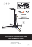
ELECTRONIC SHOW LIFT
TORRE SHOW ELECTRÓNICA
OPERATING INSTRUCTIONS USER MANUAL
MANUAL DE INSTRUCCIONES
V.04.14
LIFTING TOWER
TORRE ELEVADORA
SLIFT 4/55
SLIFT 4/55
CERTIFICATIONS / CERTIFICACIONES
BGV-C1
BGG-912
EC Conformity Declaration pursuant to the EC Machinery
Directives 89/392/CE and 98/37/CE: Manual lifters
Find a copy of the certifications at the end of this booklet.
Puede ver una copia de las certificaciones al final del manual.
MADE IN SPAIN (EU)
Manufacturer - Fabricante
PRO LIFTS S.L.
C/ Ciudad de Barcelona Nº19
Pol.Ind. Fuente del Jarro
46988 Paterna (Valencia)
Tlf Export: +34 96 171 81 86
Tlf Nacional: 96 171 81 83
[email protected] - www.prolifts.es
Este manual de usuario y catálogo anexo de piezas de repuesto es propiedad de PRO LIFTS S.L.
Queda prohibida su reproducción total o parcial por cualquier medio que la tecnología actual permita.
Deposito legal y copyright 2014. Todos los derechos reservados.
Quick operation guide
ENGLISH
GENERAL CONTENTS:
2. TECHNICAL INFORMATION
1. - Introduction
2. - Technical Information
3. - Safety precautions
4. - Maintenance
5. - Guarantee
6. - ShowLift assembly
7. - Operation panel instructions
2.1 - Towerlift: ShowLift 4/55.
2.2 - Designed for stage show, with the
effect of lifting lighting systems vertically
at different heights and speed, DMX controllable.
2.3 - Maximum load : 55 Kg (121 lb).
2.4 - Minimum load : 15 Kg (33 lb).
1. INTRODUCTION
2.5 - Maximum height : 4 m (13.12’).
Dear customer, In order to ensure a safe
and reliable operation of the Slift 4/55
towerlift please follow the instructions in
this booklet carefully. Before operating the
lift, read the instructions completely and
please note the technical information contained within this manual.
All VMB products undergo very rigorous
testing, under strict conditions and they
are monitored continuously during the
manufacturing process. In order to guarantee the lifts function and safety, only
original parts from the manufacturer must
be used. If any parts other than those of
the manufacturer are used, or the product
is modified in any way, the user forfeits all
warranty rights to claim.
VMB reserves the right to modify the product specifications without prior notice.
2.6 - Minimum height : 1.27 m (4.17’).
2.7 - Area of base : 87x90 cm
(2.85’x2.95’)
2.8 - Towerlift weight :88 Kg (194,01 lb).
2.9 - Power: 1500W
(Peak power: 3000W)
Voltage: 90V - 230V AC
Max. speed: 1 m/s - Min. speed: 0.2 m/s
2.10 - Construction material : Main body in
extruded aluminium 6082-T6 profile. Base
and legs are made of steel profile according to DIN2394. Catches and safety rack
of ST-37 steel.
2.11 - Steel core timing strap DIN AT-10.
2.12 - Adjustable stabilizing platforms with
ruber non-slip supports.
2.13 - Antirust protection, primed paint
The model type, production year and serial number must be quoted in any queries
or orders for spare parts.
PRO LIFTS S.L.
with cured polyester dust cover. The tower
is supplied with black finish.
2.14 - Wheels to transport the lift when
folded.
Depósito legal y copyright 2010. Todos los derechos reservados.
3
Quick operation guide
ENGLISH
3. SAFETY PRECAUTIONS.
3.1 - The Slift is a machine designed to elevate loads
upwards in a vertical direction, It should NEVER be
used as a platform to elevate people.
3.2 - Only place the lift on hard, flat surfaces always
checking that it is in a vertical position. Adjust the outrigger stabilisers by turning the cranks to level if necessary. NEVER use wedges or other foreign objects to
balance the lift.
3.3 - The maximum load indicated on the characteristics
label and the instructions manual should not be exceeded.
3.4 - This lift should NEVER be used to elevate a load
that has not been properly checked. It is necessary to
verify that the load is correctly supported and centred
on the appropriate lift support so that the weight of the
load will only elevate in a vertical direction.
3.6 - NEVER use the lift on a vehicle or any other mobile
surface.
PRO LIFTS S.L.
Depósito legal y copyright 2010. Todos los derechos reservados.
4
Quick operation guide
ENGLISH
3.7 - If there is a possibility of strong winds or gusts, place the lift on the ground firmly and secure the base with
the use of straps. NEVER attach a strap to a vehicle or
any other object that can possibly be moved.
3.8 - NEVER move the lift whilst if it is carrying a load.
It is not advisable to carry out any type of horizontal
movement even small positional adjustments.
3.9 - NEVER allow any team member below the load or
anybody else in the lifts operating zone.
3.10 - Take care with all obstacles above the lift and
its extension zone such as cornices, balconies, and
luminous signboards. It is very important to avoid the
presence of all types of cables below the extended lift.
3.11 - Do not use stepladders on the lift or use it as a
support for them.
3.12 - Before using the lift, check the condition of the
cable. The cable should not contain broken threads or
show any signs of crushed/flattened areas. NEVER use
faulty cables, always change them if there is any doubt. Only use steel cables reference: DIN 3060. Quality:
180KG/mm and torsion resistant.
PRO LIFTS S.L.
Depósito legal y copyright 2010. Todos los derechos reservados.
5
Quick operation guide
ENGLISH
3.13 - All sections must be lowered first, before transportation.
3.17 - Only original replacement parts should be used.
ORIGINAL
4. MAINTENANCE.
4.1 - Regularly check the state of the timing strap. If the strap has broken parts,
or if it shows any signs of crushed/flattened areas, it should be changed and
replaced immediately with a new one.
Do not use the lift if the straps are in bad
condition. Only use VMB steel core timing
straps.
4.2 - The lift is supplied from the factory
completely greased. However, it is recommended to periodically grease according
to use, the gearing, the axis bearings and
the sections.
4.3 - All lifts should undergo an annual
technical inspection carried out by an
authorized VMB dealer to check the certifications and general condition of all the
lift’s elements and security systems involved in the lift’s use.
PRO LIFTS S.L.
4.4 - Only use original spare parts to guarantee a continued security level. The
user loses all rights to warranty if any spare parts other than originals are used or
carries out any modification or alteration
to the towerlift.
4.5 - To request a spare part please indicate the corresponding code which can
be found in this manual together with the
lift’s serial number and year of manufacture.
5. GUARANTEE.
The warranty period for this lift is 2 years
from the date of purchase.
PRO LIFTS S.L. promises, that from the
date of purchase and during the warranty
period to resolve any faults that may occur, produced through defect material or
fabrication. Damage caused by improper
use, product modification, third party manipulation or accidental fire are not covered by this warranty.
Depósito legal y copyright 2010. Todos los derechos reservados.
6
Quick operation guide
ENGLISH
6.6 - Signal communication
connections:
6. - SHOWLIFT ASSEMBLY
6.1 - Place the lift in its working position,
on a firm, flat surface making use of the
transport wheels.
6.2 - Place the stabilizer plates on the
main base and secure them with the
clamping bolts.
6.3 - Level and stabilize the lift using
the adjusting bolts located at the end of
the stabilizer plates using a 8 mm Allen
wrench. Use a profesional spirit level if it
is required.
To establish communication between the
machine and the DMX console, use 3-pin
XLR connectors, located at the patch panel.
DMX connections are also separate, on
one side, the signal connection for the
lift itself, and on the other, completely independent, the signal connection for the
equipment that would be mounted on the
top tray.
PATCH PANEL FOR THE LIFT
6.4 - Place the load on the top platform
or tray, center and fix it firmly to the corresponding holes. Secure the load with
straps, binding them at the edges of the
tray. THE MAXIMUM LOAD IS 55 Kg
(121 lb). The lift should NEVER be overloaded (over 55 Kg). Safety at work is the
most important issue.
6.5 - Power connections:
Wire the power lines and power distribution. Each SLift has separate power
connections, on one side, are the connections for the functioning of the towerlift
itself, and on the other side, completely
independent, are the power connections
for the equipment that would be mounted
on the top tray. Power connections use
PowerCon connectors.
PRO LIFTS S.L.
PATCH PANEL FOR THE TOP TRAY
Depósito legal y copyright 2010. Todos los derechos reservados.
7
Quick operation guide
ENGLISH
6.7 - Connecting the equipment on the
MANUAL / DMX
DMX
top tray:
Once the towerlift connections have been
MAX HEIGHT
4000
established. Connect the power of the
equipment located on the top tray with
PowerCon cables, and 3-pin XLR for the
MIN HEIGHT
0
DMX signal. Connect the cables to the
junction box located under the tray.
RESET
7. - OPERATION PANEL
INSTRUCTIONS
LCD backlit display of 16 characters and
two lines:
UP
Top button = UP
Bottom button = DOWN
Left button = ESC
Right button = ENTER
ESC
Pressing ENTER will enter to the menu
selected, the menu value is indicated between “< >”. This means that the value has
been selected for editing:
ENTER
DMX ADRESS
<2>
DOWN
After power-up or after 15 seconds of inactivity the initial screen will appear.
SHOW LIFT 4/55
VER 2.0
For navigating through the main menu
options press UP or DOWN buttons. The
first line indicates the menu name and the
To change the DMX address use the UP
and DOWN buttons. Press ESC to exit the
menu and save the selected value. Values
between 1 and 510.
To modify the MANUAL/DMX option, use
the ENTER button. The option toggles
between MANUAL or DMX alternately
each time ENTER is pressed. Press ESC
to exit the menu and save your choice.
second line its value:
DMX ADRESS
2
PRO LIFTS S.L.
MANUAL / DMX
< MANUAL >
MANUAL / DMX
< DMX >
Depósito legal y copyright 2010. Todos los derechos reservados.
8
Quick operation guide
Whenever the MANUAL option is selected. The lift can move up and down at a
fixed speed, manually using the UP and
DOWN buttons.
Whenever the DMX option is selected,
the lift will move according to the signals
received from the control channels of the
DMX console.
MAX HEIGHT
< 4000 >
MAX HEIGHT
< SET 3245 >
Pressing the ENTER button, the tower will
do a complete reset automatically.
This means the tower will do a new search
for the starting position reference and will
erase the limits of maximum and minimum
heights.
ATTENTION: After reset, if the tower is in
DMX mode, it will move immediately to the
values requested by the DMX console.
ATTENTION: The limits of maximum and
minimum height disappear after reset.
Pressing the ENTER button, the tower will
automatically store the current position as
the maximum height.
The menu displays <SET XXXX> for a few
seconds to indicate that a new value has
been saved in memory.
MIN HEIGHT
<0>
ENGLISH
NOTE: It is recommended to set the tower
in manual mode before doing a reset, to
ensure that the tower will not do sudden
movements just after the reset finishes.
MIN HEIGHT
< SET 550 >
Pressing the ENTER button, the tower will
automatically store the current position as
the minimum height.
The menu displays <SET XXXX> for a few
seconds to indicate that a new value has
been saved in memory.
RESET
PRESS > TO RESET
PRO LIFTS S.L.
RESET
< RESET >
Depósito legal y copyright 2010. Todos los derechos reservados.
9
Manual de instrucciones
ESPAÑOL
CONTENIDOS GENERALES:
2. INFORMACIÓN TÉCNICA
1. - Introducción
2.1 - Torre elevadora Showlift 4/55.
2. - Información técnica
5. - Garantía
2.2 - Diseñada para show de escenario,
con el efecto de levantar sistemas de iluminación en sentido vertical a diferentes
alturas y velocidad, controlable por DMX.
6. - Montaje de la ShowLift
2.3 - Carga máxima: 55 Kg (121 lb).
7. - Instrucciones del panel de operación
2.4 - Carga mínima: 15 Kg (33 lb)
3. - Precauciones de seguridad
4. - Mantenimiento
2.5 - Altura máxima: 4 m (13,12’).
2.6 - Altura mínima: 1,27 m (4,17’).
1. - INTRODUCCIÓN
Estimado cliente: Con el fin de garantizar
un funcionamiento seguro y fiable de la
torre elevadora Showlift 4/55 por favor,
siga cuidadosamente las instrucciones de
este folleto. Antes de manipular la torre
elevadora lea las instrucciones completas
y tenga en cuenta la información técnica contenida en este manual. Todos los
productos de VMB se someten a pruebas
muy rigurosas, en condiciones estrictas y
son monitorizados continuamente durante el proceso de fabricación.
Con el fin de garantizar el correcto funcionamiento y seguridad de los elevadores,
sólo deben ser utilizadas piezas originales del fabricante. Si se utilizan piezas
que no sean las originales del fabricante,
o el producto se modifica de alguna manera, el usuario pierde todos los derechos
de garantía.VMB se reserva el derecho
de modificar las especificaciones del producto sin previo aviso. El tipo de modelo,
año de producción y el número de serie
debe ser citado en cualquier consulta o
pedido de piezas de recambio.
PRO LIFTS S.L.
2.7 - Área de la base: 87x90 cm
(2.85’x2.95’)
2.8 - Peso de la torre completa:
88 Kg (194,01 lb).
2.9 - Consumo: 1500W
(Pico de consumo: 3000W)
Voltaje: 90V - 230V AC
Max. speed: 1 m/s - Min. speed: 0.2 m/s
2.10 - Material de construcción: Cuerpo
en perfil de aluminio extruido 6082-T6.
La base de placa de acero según norma
DIN2394.
2.11 - Correa dentada con alma de acero.
DIN AT-10
2.12 - Plataformas estabilizadoras ajustables con soportes de goma antideslizantes.
2.13 - Protección anti-óxido, imprimación
con pintura de polvo poliester al horno.
La torre es suministrada con acabado en
negro.
2.14 - Ruedas para el transporte del elevador cuando está plegado.
Depósito legal y copyright 2010. Todos los derechos reservados.
10
Manual de instrucciones
ESPAÑOL
3. PRECAUCIONES DE SEGURIDAD.
3.1 - La Slift 4/55 es una máquina diseñada para la elevación de cargas en dirección vertical, NUNCA se debe
utilizar como plataforma elevadora de personas.
3.2 - Colocar el elevador sólo en superficies firmes y
planas, verificando que está en posición vertical. Ajuste
los niveladores girando los pomos de ajuste hasta nivelar, si es necesario. Nunca utilice cuñas u otros objetos
extraños para equilibrar el elevador.
3.3 - La carga máxima indicada en la placa de características y en las instrucciones del manual nunca debe
ser excedida.
3.4 - Este elevador NUNCA debe utilizarse para elevar una carga que no ha sido correctamente revisada.
Es necesario verificar que la carga está correctamente
apoyada y centrada en el soporte de elevación apropiado para que el peso de la carga sólo actúe en una
dirección vertical.
3.6 - NUNCA use el elevador sobre un vehículo o cualquier superficie móvil.
PRO LIFTS S.L.
Depósito legal y copyright 2010. Todos los derechos reservados.
11
Manual de instrucciones
ESPAÑOL
3.7 - Si existe la posibilidad de vientos fuertes o ráfagas, coloque el elevador en el suelo con firmeza y fije
la base mediante tirantes tensores. Nunca fije un tirante a un vehículo o cualquier otro objeto que se pueda
mover.
3.8 - NUNCA mueva el elevador mientras esté cargado. No es aconsejable llevar a cabo cualquier tipo de
movimiento horizontal, ni tan sólo pequeños ajustes de
posición.
3.9 - NUNCA permita que ningún miembro del equipo o
cualquier otra persona se sitúe debajo de la carga en la
zona de operación de las torres elevadoras.
3.10 - Tenga cuidado con todos los obstáculos por
encima de la elevación y su zona de extensión, como
cornisas, balcones, letreros luminosos, etc. Es muy importante evitar la presencia de todo tipo de cables por
debajo de la torre extendida.
3.11 - No usar escaleras encima del elevador ni utilizarlo como un apoyo para éstas.
3.12 - Antes de utilizar el elevador, compruebe el estado de la correa. La correa no debe contener zonas
rotoa o mostrar signos de áreas aplastadas/aplanadas.
NUNCA use correas defectuosas, siempre debe cambiarlos si hay alguna duda. Utilice solo la correa dentada VMB con alma de acero DIN AT-10.
PRO LIFTS S.L.
Depósito legal y copyright 2010. Todos los derechos reservados.
12
Manual de instrucciones
ESPAÑOL
3.13 - Todas los tramos deben ser bajados antes del
transporte.
3.17 - Sólo deben ser utilizadas piezas de repuesto
originales de VMB PRO LIFTS S.L.
ORIGINAL
4. MANTENIMIENTO
4.1 - Comprobar periódicamente el estado de la correa dentada, si esta presenta zonas dañadas o rotas, o si muestra
signos de aplastamiento / aplanamiento,
debe ser sustituido inmediatamente por
uno nuevo. No use el elevador si las correas están en mal estado.
4.2 - La torre elevadora es suministrada
de fábrica completamente engrasada.
Sin embargo, se recomienda un engrase
periódico, según el uso de las ruedas de
fricción, los cojinetes de eje, y los tramos.
4.3 - Todos los elevadores deben someterse a una inspección técnica anual llevada a cabo por un distribuidor autorizado
VMB para comprobar las certificaciones y
el estado general de todos los elementos
de elevación y sistemas de seguridad que
intervienen en el uso del elevador.
4.4 - Utilice únicamente piezas de repuesto originales para garantizar el nivel de
seguridad de forma continuada. El usuaPRO LIFTS S.L.
rio pierde todos los derechos de garantía
si las piezas de repuesto utilizadas no son
originales o se utilizan o se lleva a cabo
cualquier modificación o alteración de la
torre elevadora.
4.5 - Para solicitar una pieza de recambio indique el código correspondiente que
se encuentra en este manual junto con el
número de serie de la torre y el año de
fabricación.
5. GARANTÍA
El período de garantía para este elevador
es de 2 años a partir de la fecha de compra.
PRO LIFTS S.L. se compromete, que a
partir de la fecha de compra y durante el
período de garantía, a resolver los fallos
que puedan producirse, debidos a material defectuoso o fabricación. Los daños
causados por un uso inadecuado, modificación del producto, la manipulación de
terceros o incendio accidental no están
cubiertos por esta garantía.
Depósito legal y copyright 2010. Todos los derechos reservados.
13
Manual de instrucciones
6. - MONTAJE DE LA SHOWLIFT
6.1 - Colocar la torre elevadora sobre una
superficie firme y plana de la zona de trabajo sirviendose de las ruedas de transporte.
6.2 - Colocar las placas estabilizadoras
en la parte superior de la base y fijarla
mediante los pernos de sujeción.
6.3 - Nivelar y estabilizar la torre mediante los pernos de ajuste situados en los
extremos de las placas estabilizadoras
ayudandose de una llave Allen de 8 mm.
Si se requiere utilice un nivel profesional.
ESPAÑOL
6.6 - Conexiones de comunicación de
señal: Para establecer la comunicación
entre la máquina y la consola DMX, utilizar los conectores XLR de 3 polos situados en el panel de conexiones.
Las conexiones de señal DMX también
está separadas, por un lado, la conexión
de señal para la propia torre, y por otro
lado, completamente independiente, la
conexión de señal para los equipos que
se monten en el cabezal.
PANEL DE CONEXIONES DE LA TORRE
6.4 - Colocar la carga sobre la plataforma
o bandeja superior, centrarla y fijarla con
firmeza a los orificios correspondientes.
Asegurar la carga con cinchas, sujetandola a los bordes de la bandeja.
La CARGA MÁXIMA es de 55 kg (121 lb),
la torre NUNCA debe ser sobrecargada
(más de 55 kg). La seguridad en el trabajo
es el elemento más importante.
6.5 - Conexión de alimentación:
Cablear las líneas de alimentación y distribución de energía. Cada SLift tiene las
conexiones de corriente separadas, por
un lado la conexión para el funcionamiento de la propía torre y por otro lado, completamente independiente, la conexión
de alimentación para los equipos que se
monten en el cabezal. Las conexiones de
alimentación usan conectores PowerCon.
PRO LIFTS S.L.
PANEL DE CONEXIONES DE LA BANDEJA
Depósito legal y copyright 2010. Todos los derechos reservados.
14
Manual de instrucciones
ESPAÑOL
6.7 - Conexión de los equipos de la
MAX HEIGHT
4000
bandeja superior: Una vez establecidas
las conexiones al panel de la torre. Conectar los equipos situados en la bandeja
MIN HEIGHT
0
superior con cables PowerCon para alimentación, y XLR de 3 polos para la se-
RESET
ñal DMX. Conectar los cables a la caja de
conexiones situada en la parte inferior del
lateral de la bandeja.
7. - INSTRUCCIONES DEL PANEL
DE OPERACIÓN DE LA TORRE
Presionando ENTER se entra en el menú
y el valor del menú aparece indicado entre signos “<>”. Esto significa que se ha
seleccionado el valor para modificarlo:
DMX ADRESS
<2>
Display LCD retroiluminado de 16 caracteres y dos renglones:
UP
Tecla superior = UP
Tecla inferior = DOWN
Tecla izquierda = ESC
Tecla derecha = ENTER
ESC
ENTER
DOWN
Después del encendido o después de 15
segundos sin actividad se muestra la pantalla inicial.
SHOW LIFT 4/55
VER 2.0
Presionando UP o DOWN se navega por
las opciones principales del menú. El primer renglón indica el nombre del menú y
el segundo renglón su valor:
DMX ADRESS
2
MANUAL / DMX
DMX
PRO LIFTS S.L.
Para modificar la dirección DMX utilizar
las teclas UP y DOWN. Presionar ESC
para salir del menú y grabar el valor elegido. Valores entre 1 y 510.
Para modificar la opción MANUAL/DMX
utilizar la tecla ENTER. La opción cambiará entre MANUAL y DMX en forma alternada cada vez que se presione ENTER.
Presionar ESC para salir del Menú y grabar la opción elegida.
MANUAL / DMX
< MANUAL >
MANUAL / DMX
< DMX >
Siempre que se encuentre seleccionada
la opción MANUAL. La torre podrá moverse hacia arriba y hacia abajo a una velocidad fija, en forma manual utilizando las
teclas UP y DOWN.
Siempre que se encuentre seleccionada
la opción DMX, La torre se moverá de
acuerdo a las señales que reciba desde
los canales de control.
Depósito legal y copyright 2010. Todos los derechos reservados.
15
Manual de instrucciones
MAX HEIGHT
< 4000 >
MAX HEIGHT
< SET 3245 >
ATENCIÓN: Los límites de altura máxima
y mínima desaparecerán luego del reset.
Pulsando la tecla ENTER, automáticamente se memoriza la posición actual de
la torre como la altura máxima.
El menú mostrará <SET XXXX> por unos
segundos, para indicar que el nuevo valor
se ha grabado en la memoria.
MIN HEIGHT
<0>
ESPAÑOL
NOTA: Es recomendable realizar el Reset
poniendo antes la torre en modo Manual,
para asegurarse que no se producirán
movimientos sorpresivos de la misma
apenas finalice el proceso.
MIN HEIGHT
< SET 550 >
Pulsando la tecla ENTER, automáticamente se memoriza la posición actual de
la torre como la altura mínima. El menú
mostrará <SET XXXX> por unos segundos, para indicar que el nuevo valor se ha
grabado en la memoria.
RESET
PRESS > TO RESET
RESET
< RESET >
Pulsando la tecla ENTER, automáticamente se realiza un Reset total de la torre.
Esto es: una nueva búsqueda de la referencia de posición inicial y el borrado de
los límites de alturas máxima y mínima.
ATENCIÓN: Luego del reset, si la torre se
encuentra en modo DMX, se moverá inmediatamente a los valores que solicite la
consola DMX.
PRO LIFTS S.L.
Depósito legal y copyright 2010. Todos los derechos reservados.
16
PRO LIFTS S.L.
Depósito legal y copyright 2010. Todos los derechos reservados.
17
CERTIFICATION 209 / 2013
EC Conformity Declaration pursuant to the EC Machinery Directives
89/392/CE and 98/37/CE: Manual lifters.
- MANUFACTURER:
PRO LIFTS S.L.
Pol. Ind. Inglés. Nave 6
E-46181 Benisanó- VALENCIA
- MACHINE TYPE:
Telescopic towwerlift for trussing structures.
- MODEL:
S.LIFT 4/55
- DESCRIPTION:
Towerlift with 4 telescopic profiles.
Minimum height: 1.27 m
Maximum height: 4.1 m
Maximum load: 55 Kg
Area of base: 0.87 x 0.86 m
We hereby declare that VMB towerlifts model TE-074 satisfy the EC Machinery Directive
89/392/CE, 98/37/CE, regulations, relevant EC directives and amendments when
used for lifting and lowering loads as directed.
Benisanó, January 2013
PRO LIFTS S.L.
Depósito legal y copyright 2010. Todos los derechos reservados.
18
PRO LIFTS S.L.
Depósito legal y copyright 2010. Todos los derechos reservados.
19
facebook / vmblifts
Canal VMBLifts
For further information follow the advise of our technicians:
Para más información consulte con nuestros técnicos en:
PRO LIFTS S.L.
C/ Ciudad de Barcelona Nº19
Pol. Ind. Fuente del Jarro
46988 Paterna (Valencia) Spain
Tlf Export: +34 96 171 81 86
Tlf Nacional: 96 171 81 83
email: [email protected]
web: www.prolifts.es