1
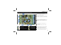
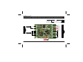
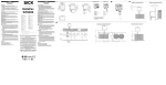
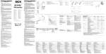
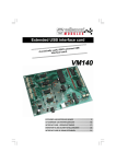
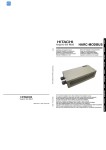
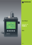
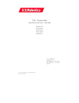
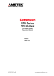
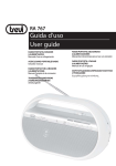
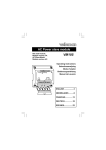
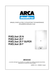
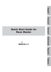
USB EXPERIMENT INTERFACE BOARD VM110N short user manual - Beknopte gebruikershandleiding - Notice abrégée - Kurzbedienungsanleitung Manual del usuario corto WARRANTY This product is guaranteed against defects in components and construction from the moment it is purchased and for a period of TWO YEAR starting from the date of sale. This guarantee is only valid if the unit is submitted together with the original purchase invoice. VELLEMAN Ltd limits its responsibility to the reparation of defects or, as VELLEMAN components Ltd deems necessary, to the replacement or reparation of defective components. Costs and risks connected to the transport, removal or placement of the product, or any other costs directly or indirectly connected to the repair, will not be reimbursed by VELLEMAN components Ltd. VELLEMAN components Ltd will not be held responsible for any damages caused by the malfunctioning of a unit. GARANTIE Ce produit est garanti contre les défauts des composantes et de fabrication au moment de l’achat, et ce pour une période de deux ans à partir de la date d’achat. Cette garantie est uniquement valable si le produit est accompagné de la preuve d’achat originale. Les obligations de VELLEMAN S.A. se limitent à la réparation des défauts ou, sur seule décision de VELLEMAN S.A., au remplacement ou à la réparation des pièces défectueuses. Les frais et les risques de transport, l’enlèvement et le renvoi du produit, ainsi que tous autres frais liés directement ou indirectement à la réparation, ne sont pas pris en charge par VELLEMAN S.A. VELLEMAN S.A. n’est pas responsable des dégâts, quels qu’ils soient, provoqués par le mauvais fonctionnement d’un produit. WAARBORG Dit produkt is gewaarborgd wat betreft gebreken in materialen en vakmanschap op het ogenblik van de aankoop en dit gedurende een periode van TWEE JAAR vanaf de aankoop. De waarborg geldt enkel indien het produkt voorgelegd wordt samen met het origineel aankoop bewijs. De verplichtingen van VELLEMAN N.V. beperken zich tot het herstellen van defecten of, naar vrije keuze van VELLEMAN N.V., tot het vervangen of herstellen van defecte onderdelen. Kosten en risico’s van transport; het wegnemen en terugplaatsen van het produkt, evenals om het even welke andere kosten die rechtstreeks of onrechtstreeks verband houden met de herstelling, worden niet door VELLEMAN N.V. vergoed. VELLEMAN N.V. is niet verantwoordelijk voor schade van gelijk welke aard, veroorzaakt door het falen van een product. GARANTIE Dieses Produkt trägt eine Garantie für fehlerhaftes Material oder Verarbeitungsschäden im Moment des Ankaufs. Sie ist ZWEI JAHRE gültig ab Ankaufsdatum. Die Garantie kann nur beansprucht werden, wenn das Produtk mit der Originalrechnung abgegeben wird. Die Verpflichtungen der VELLEMAN AG beschränken sich auf die Aufhebung der Fehler, oder, nach freier Wahl der VELLEMAN AG, auf den Austausch oder die Reparation der fehlerhaften Teile. Kosten und Risiken des Transports; das Entfernen und Wiedereinsetzen des Produkts, sowie alle anderen Kosten die direkt oder indirekt mit der Reparation in Verbindung gebracht werden können, werden durch die VELLEMAN AG nicht zurückerstattet. VELLEMAN AG ist nicht für Schäden gleich welcher Art, entstanden aus der fehlerhaften Funktion des Produkt, haftbar. GARANTÍA El producto está garantizado durante un período limitado de DOS AÑO a partir de la fecha original de compra. La garantía sólo tendrá validez cuando se presente el producto con la factura de compra original. VELLEMAN S.A. se limitará a reparar defectos pero es libre de reparar o reemplazar partes defectuosas. VELLEMAN S.A. no reembolsará los gastos de transporte o riesgos, ni los gastos para trasladar y reinstalar el producto así como todo otro gasto directamente o indirectamente relacionado con la reparación. VELLEMAN S.A. no asumirá ninguna responsabilidad por daños de cualquier naturaleza causados por un producto defectuoso. -2- Diagnostic / test software - Diagnostische software / testsoftware - Diagnose-/ Testsoftware - Software Diagnóstico / Software de Prueba UK See the product page on our website for the latest available software & manual NL Download de laatst beschikbare software en handleiding op de productpagina van onze website. FR Consultez la fiche technique de l'article sur notre site pour les nouveaux logiciels et manuel disponibles. D Siehe das Produkt auf unserer Website für die neueste Software und Gebrauchsanweisung. ES Véase el producto en nuestra página web para el software e manual más reciente disponible. -3- Description - Beschrijving - Beschreibung - Descripción 4 2 9 11 3 5 10 6 Internal Test-voltage - Interne analoge testspanning - tension d'essai analogique interne analoge Testspannung - tensión de prueba analógica interna Externe analoge spanning A1/A2 - Externe analoge spanning A1/A2 - Tension analogique externe A1/A2 - Externe analoge Spannung A1/A2 - Tensión analógica externa A1/A2 7 OUT - UITGANG - SORTIE - AUSGANG - SALIDA INPUT - INGANG - ENTREÈ - EINGANG - ENTRADA 1 8 Regeling / Regeling / Reéglage / Regelung / Ajuste Internal Test-voltage Interne analoge testspanning Tension d'essai analogique Interne analoge Testspannung Tensión de prueba analógica interna -4- 1 Analog input adjustment - Regeling analoge ingangsgevoeligheid - ajustement d’entrée analogique ajuste de la sensibilidad de entrada analógica - Regelung der analogen Eingangsempfindlichkeit 2 2 analogue inputs - 2 analoge ingangen - 2 entrées analogiques - 2 analoge Eingänge - 2 entradas analógicas 3 5 digital inputs - 5 digitale ingangen - 5 entrées numériques - 5 digitale Eingänge - 5 entradas digitales 4 2 analogue outputs - 2 analoge uitgangen - 2 sorties analogiques - 2 analoge Ausgänge - 2 salidas analógicas 5 8 digital open collector outputs - 8 digitale open-collector uitgangen - 8 interrupteurs de sortie numériques à collecteur ouvert - 8 digitale Ausgangsschalter mit offnemen Kollektor - 8 interruptores de salida digitales con colector abierto 6 Test buttons - testknoppen - boutons de test - Test - Tasten - botones de prueba 7 USB 8 Output LED indicators - LED uitgangindicaties - LED d’indication de sortie - Indicadores LED de salida - LEDAusgansanzeigen 9 Adress selection - adresselectie - Sélection d'adresse Adressenauswahl - Selección de dirección 10 Digital input protection with ULN2803 - Digitale ingangsbescherming met ULN2803 - protection d’entrée numérique avec ULN2803 - Protección de entrada digital con ULN2803 - Digitaler Eingangsschutz mit ULN2803 11 Digital output protection with ULN2803 - Digitale uitgangsbescherming met ULN2803 - protection de sortie numérique avec ULN2803 - Protección de salida digital con ULN2803 - Digitaler Ausgangsschutz mit ULN2803 Connection diagram - Aansluitschema - Schema de connexion - Connection scheme - Esquema de conexiones ANALOG PWM PWM1, PWM2 DAC1 , DAC2 0...5V Open collector + PWM2 (+) - PWM1 (+) DAC2 (+) ANALOG I N P U T DAC1 (+) DIGITAL -5- + DC voltage 5 ... 30V O U T P U T WARNING UK : PLEASE NOTE THAT THE GROUND OF THE BOARD IS NOT ISOLATED FROM THE COMPUTER GROUND! ND : DE MASSA VAN HET BORD IS NIET GESCHEIDEN MET DE COMPUTER MASSA! FR : REMARQUEZ QUE LA TERRE DE LA PLAQUE N'EST PAS ISOLEE DE LA TERRE DE L'ORDINATEUR ! D : BITTE VERGEWISSEM SIE SICH, DASS SICH DIE ERDUNG DER PLATINE UND DIE ERDUNG DES COM PUTERS NICHT GEGENSEITIG ISOLIERT SIND! ES : ¡OBSERVE QUE LA TIERRA DE LA PLACA NO ESTÁ AISLADO DE LA TIERRA DEL ORDENADOR! Specifications and features The VM110N interface board has 5 digital input channels and 8 digital output channels. In addition, there are two analogue inputs and two analogue outputs with 8 bit resolution. The number of inputs/outputs can be further expanded by connecting more (up to a maximum of four) cards to the PC's USB connectors. All communication routines are contained in a Dynamic Link Library (DLL) K8055D.DLL. You may write custom Windows (XP or higher) applications in Delphi, Visual Basic, C++ Builder or any other 32-bit Windows application development tool that supports calls to a DLL. Source code for Visual Basic , Visual C++, Visual C#, Excel, Delphi and Borland C++ Builder included. Features minimum system: Pentium class CPU USB1.1 or higher connection Windows xp or higher DIAGNOSTIC / TEST SOFTWARE: separate output / input test clear all / set all function counter function on inputs 1 and 2 with adjustable debounce (max 2KHz depends on total I/O load) analogue output set sliders analogue input bar-graph indication 100% compatible with: VM110 & K8055 cards Specifications 5 digital inputs (0= ground, 1= open) (on-board test buttons provided) 2 analogue inputs with attenuation and amplification option (internal test +5V provided) 8 digital open collector output switches (max 50V/100mA) (on-board LED indication) 2 analogue outputs: 0 to 5V, output resistance 1K5 PWM 0 to 100% open collector load max 100mA / 40V (on-board LED indication) general respons time: 2ms per command power supply: through USB approx. 70mA dimensions: 110 x 80mm / 4.3 x 3.2" -7- Kenmerken en Specificaties De VM110N interfacekaart heeft 5 digitale ingangskanalen en 8 digitale uitgangskanalen. Bovendien beschikt u over twee analoge ingangen en twee analoge uitgangen met 8-bit resolutie. U kunt het aantal ingangen/uitgangen verder uitbreiden door max. 4 kaarten aan te sluiten op de USB connectors van uw pc. Alle communicatieroutines zitten in een Dynamic Link Library (DLL). Dit bestand heet 'K8055D.DLL'. U kunt op maat gemaakte Windows (XP of hoger) toepassingen schrijven in Delphi, Visual Basic, C++ Builder of om het even welk ander 32-bit ontwikkelingstool voor Windows die een DLL kan oproepen. Broncode voor Visual Basic, Visual C++, Visual C#, Excel, Delphi en Borland C++ Builder meegeleverd. Kenmerken minimum systeemvereisten: CPU pentium-klasse USB1.1 aansluiting of hoger Windows XP of hoger DIAGNOSTISCHE SOFTWARE / TESTSOFTWARE: afzonderlijke uitgangs- / ingangstest clear all / set all-functie tellerfunctie op ingangen 1 en 2 met regelbare ontdendering (max 2kHz afhankelijk van de totale ingangs-/uitgangsbelasting) analoge uitgang met schuifregelaars analoge ingang met bargraph aanduiding 100% compatibel met: VM110 & K8055 interfacekaarten Specificaties 5 digitale ingangen (0 = aarde, 1= open) (toestel is uitgerust met testknoppen) 2 analoge ingangen met verzwakkings- en versterkingsoptie (interne testaansluiting +5V is voorzien) 8 digitale open-collector uitgangsschakelaars (max 50V/100mA) (LED aanduiding) 2 analoge uitgangen: 0 tot 5V, uitgangsweerstand 1K5 PWM 0 tot 100% open-collector uitgangen max 100mA / 40V (LED aanduidingen) gemiddelde conversietijd: 2ms per commando voeding: via USB ongeveer 70mA afmetingen: 110 x 80mm -8- Eigenschaften und Technische Daten La carte interface VM110N est pourvu de 5 canaux d'entrée numériques et 8 canaux de sortie Die VM110N Interfaceplatine hat 5 digitale Eingangskanäle und 8 digitale Ausgangskanäle. Es gibt auch noch 2 zusätzliche analoge Eingänge und 2 analoge Ausgänge mit einer 8-Bit Auflösung. Die Anzahl der Ein-und Ausgänge kann noch weiter vergrößert werden, wenn (bis maximal 4) Karten mit den USB-Anschlüssen des PCs verbunden werden. Alle Kommunikationsprogramme sind in einer Dynamic Link Library (DLL) K8055D.DLL gespeichert. Sie können maßgeschneiderte Windows (XP oder höher) Applikationen in Delphi, Visual Basic, C++ Builder oder jedem anderen 32-bit Windows-Hilfsprogramm für Applikationen, das DLL unterstützt, schreiben. Quellcode für Visual Basic, Visual C++, Visual C#, Excel, Delphi und Borland C++ Builder mitgeliefert. Eigenschaften minimale Systemanforderungen: Pentium-Klasse CPU USB1.1 oder höher Windows XP oder höher DIAGNOSE-/TESTSOFTWARE: separater Eingangs-/Ausgangstest 'Alles löschen'-/'alles festsetzen'-Funktion Zähler-Funktion bei Eingängen 1 und 2 mit anpassbarer Entprellung (max. 2KHz, hängt von der gesamten I/O-Belastung ab.) Schieber (analoger Ausgang) Säulendiagramm (analoger Eingang) 100% kompatibel mit: VM110 & K8055 Interfaceplatine Technische Daten 5 digitale Eingänge (0= GND, 1= offen) (Test-Tasten auf der Platine) 2 analoge Eingänge mit Option für Dämpfung und Verstärkung (interner Test +5V vorgesehen) 8 digitale Ausgangsschalter mit offenem Kollektor (max 50V/100mA) (LED-Anzeige auf der Platine) 2 analoge Ausgänge: 0 bis 5V, Ausgangswiderstand 1K5 PWM 0 bis 100% 'offener Kollektor'-Ausgang max 100mA / 40V (LED-Anzeige auf der Platine) allgemeine Konvertierungszeit: 2ms pro Befehl Stromversorgung: über USB ungefähr 70mA Abmessungen: 110 x 80mm -9- Características & Especificaciones La tarjeta interface VM110N está equipada con 5 canales de entrada digitales y 8 canales de salida digitales. Además, está provista de 2 entradas analógicas y 2 salidas analógicas con una resolución 8 bit. Es posible aumentar el número de entradas/salidas para permitir la conexión de máx. 4 tarjetas a los conectores USB de su PC. Todas las rutinas de comunicación se guardan en una Dynamic Link Library (DLL). El fichero en cuestión se llama 'K8055D.DLL'. Escriba aplicaciones Windows (XP o superior) a medida en Delphi, Visual Basic, C++ Builder o cualquier otra herramienta de desarrollo de 32 bits para Windows que soporta DLL. Código fuente para Visual Basic, Visual C++, Visual C#, Excel, Delphi y Borland C++ Builder incluido. Características exigencias mínimas del sistema: CPU clase Pentium conexión USB1.1 o superior Windows XP o superior SOFTWARE DIAGNÓSTICO / SOFTWARE DE PRUEBA: pruebas de entrada/salida separadas función 'clear all / set all' función contador para entradas 1 y 2 con eliminación del rebote (debounce delay) ajustable (máx. 2KHz según la carga de entrada/salida total) salida analógica con deslizadores entrada analógica con indicación barra gráfica 100% compatible con: VM110 & K8055 Especificaciones 5 entradas digitales (0 = tierra, 1= abierto) (el aparato está provisto de botones de prueba) 2 entradas analógicas con atenuación y ganancia opcionales (conexión de prueba interna +5V provista) 8 interruptores de salida digitales con colector abierto (máx. 50V/100mA) (indicación LED) 2 salidas analógicas: de 0 a 5V, resistencia de salida 1K5 PWM 0 a 100% salidas con colector abierto máx. 100mA / 40V (indicaciones LED) tiempo de conversión media: 2ms por orden alimentación: por USB ± 70mA dimensiones: 110 x 80mm - 10 - SAFETY INSTRUCTIONS SICHERHEITSHINWEISE All repairs should be executed by qualified technicians. Avoid the installation of the module in locations with standing or running water or excessive Lassen Sie Reparaturen durch Fachleute erfolgen Installieren Sie das Modul nicht in einer Umgebung mit stehendem oder humidity. Indoor use only ! fließendem Wasser oder in einer sehr feuchten Umgebung Handle the module gently and carefully. Dropping it can damage the circuit board. Never exceed the protection limit values indicated in the specifications. As safety requirement vary, please check with your local authorities. Velleman modules are not suitable for use or as part of life support systems, or systems that might create hazardous situations of kind.. Gehen Sie behutsam mit dem Modul um. Es fallen lassen, kann die Leiterplatte und das Gehäuse beschädigen. Überschreiten Sie nie die in den technischen Daten erwähnten Eingangsgrößen. Sicherheitsvorschriften können sich ändern, bitte beachten Sie die lokalen Vorschriften Ihres Landes. Der von Ihnen gekaufte Bausatz ist aber für den Privatgebrauch konzipiert VEILIGHEIDSAANWIJZINGEN Reparaties mogen uitsluitend uitgevoerd worden door vakkundige personen. Installeer de module niet op plaatsen met staand of stromend water of in ruimtes met een te hoge vochtigheidsgraad. Binnengebruik enkel! een ruwe behandeling. Stoten of laten vallen kunnen ernstige schade aanbrengen. Overschrijdt nooit de opgegeven veiligheidswaarden in de specificaties. Vermits de veiligheid vereisten verschillen van plaats tot plaats, dient U ervoor te zorgen dat Uw montage voldoet aan de plaatselijke geldende vereisten. Velleman modules zijn niet geschikt voor gebruik in of als gedeelte van systemen welke levensfuncties in stand houden of systemen welke gevaarlijke situaties van gelijk welke aard kunnen veroorzaken. und nich für den Einsatz in Lebenserhaltenden oder Lebensrettenden Systemen oder unter außergewöhnlichen Umweltbedingungen (Ex-systeme) geeinet. Vermijd LAS MEDIDAS DE SEGURIDAD El servicio debe ser realizado por personal especializado No instale el módulo en un lugar con agua estancada o agua corriente, ni en lugares excesivamente húmedos. Manéjese con cuidado. Dejar caer el dispositivo puede dañar el circuito impreso y la caja. Nunca exceda los valores límites indicados en las especificaciones. Las exigencias en materia de seguridad varían de un lugar a otro. Asegúrese que el montaje realizado sea conforme a las exigencias en vigor de su localidad. CONSIGNES DE SÉCURITÉ All repairs should be executed by qualified technicians. Toute réparation doit être exécutée par du personnel qualifié. Évitez l’installation de ce module à proximité d’eau courante ou dormante ou à une endroit avec un taux d’humidité trop élevé. Evitez les manipulations brutales. Un chute pourrait endommager le boîtier ou les plaque et pourrait causer des défauts. Ne jamais excéder les valeurs limites de protection indiquées dans les spécifications. Etant donné que les exigences en matière de sécurité varient d’un lieu à l’autre, vous devez vous assurer que votre montage satisfait aux exigences. Les modules Velleman ne conviennent pas pour une utilisation dans ou comme parties de systèmes servant à assurer des fonctions de survie ou des systèmes pouvant entraîner des situations dangereuses, de quelque nature qu‘elles soient. - 11 - Los modulo Velleman no son adecuados para una utilización dentro o corno sistema destinado a garantizar funciones para sobrevivir o sistemas conllevando situaciones peligrosas sea cual su naturaleza. VELLEMAN NV Legen Heirweg 33, B-9890 GAVERE Belgium (Europe) Modifications and typographical errors reserved - © Velleman nv, HVM110NG’1 - 2014 (rev.1)