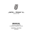
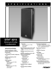
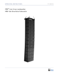
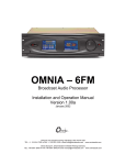
1
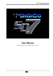
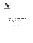
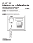
PCX 4000
User's Manual
Manual del Usuario
English
PCX 4000
High Precision Stereo 2/3-Way Mono 4-Way Crossover
Crossover de Alta Precisión Estéreo 2/3-Vías Mono 4-Vías
Español
ENGLISH . . . . . . . . . . . . . . . . . . . . . . . . . . . . . . . . . . . . . . . . . . . . . . . . . . I
ESPAÑOL ..................................................II
V1.1 06/01/2012
English
USER'S MANUAL
CONTENTS
INTRODUCTION
1
FEATURES
1
QUICK SETUP
1
OPERATING THE PCX4000
1
2-Way Stereo Operation
1
Front Panel
1
Rear Pane
2
3-Way Stereo Operation
3
Front Panel
3
Rear Panel
4
4-Way Mono Operation
5
Front Panel
5
Rear Panel
6
APPLICATION
6
SPECIFICATIONS
8
APPENDIX
DIMENSIONS
1
BLOCK DIAGRAM
2
Phonic preserves the right to improve or alter any information within this
document without prior notice
PCX4000
IMPORTANT SAFETY INSTRUCTIONS
English
The apparatus shall not be exposed to dripping or splashing and that no objects
with liquids, such as vases,
shall be placed on the apparatus. The MAINS plug is used as the disconnect device, the disconnect device shall
remain readily operable.
Warning: the user shall not place this apparatus in the
can be easily accessible.
area during the operation so that the mains switch
1. Read these instructions before operating this
apparatus.
CAUTION
2. Keep these instructions for future reference.
RISK OF ELECTRIC SHOCK
DO NOT OPEN
3. Heed all warnings to ensure safe operation.
4. Follow all instructions provided in this document.
5. Do not use this apparatus near water or in locations
where condensation may occur.
6. Clean only with dry cloth. Do not use aerosol or liquid
cleaners. Unplug this apparatus before cleaning.
. Do not block any of the ventilation openings. Install
in accordance with the manufacturer’s instructions.
CAUTION: TO REDUCE THE RISK OF ELECTRIC SHOCK,
DO NOT REMOVE COVER (OR BACK)
NO USER SERVICEABLE PARTS INSIDE
REFER SERVICING TO QUALIFIED PERSONNEL
The lightning flash with arrowhead symbol, within an
equilateral triangle, is intended to alert the user to the
presence of uninsulated “dangerous voltage” within the
product’
8. Do not install near any heat sources such as radiators,
heat registers, stoves, or other apparatus (including
.
9. Do not defeat the safety purpose of the polarized or
grounding-type plug. A polarized plug has two blades
with one wider than the other. A grounding type plug
has two blades and a third grounding prong. The wide
blade or the third prong is provided for your safety. If
the provided plug does not into your outlet, consult
an electrician for replacement of the obsolete outlet.
10. Protect the power cord from being walked on or
pinched particularly at plug, convenience receptacles,
and the point where they exit from the apparatus.
11. Only use attachments/accessories
manufacturer.
magnitude to constitute a risk of electric shock to persons.
The exclamation point within an equilateral triangle is intended to alert the user to the presence of important operating and maintenance (servicing) instructions in the literature
accompanying the appliance.
WARNING: To reduce the risk of
or electric shock, do
not expose this apparatus to rain or moisture.
CAUTION: Use of controls or adjustments or performance
of procedures other than those
may result in
hazardous radiation exposure.
by the
12. Use only with a cart, stand, tripod, bracket, or
table
by the manufacturer, or sold with
the apparatus. When a cart is used, use caution
when moving the cart/apparatus
combination to avoid injury from tipover.
13. Unplug this apparatus during lighting
storms or when unused for long
periods of time.
14. Refer all servicing to
service personnel.
Servicing is required when the apparatus has been
damaged in any way, such as power-supply cord or
plug is damaged, liquid has been spilled or objects
have fallen into the apparatus, the apparatus has
been exposed to rain or moisture, does not operate
normally, or has been dropped.
PCX4000
QUICK SETUP
Congratulations on your purchase of the PCX4000, a quality high
precision 2-way stereo, 3-way stereo, 4-way mono crossover with
a multitude of built-in features, such as low pass filters, adjustable
limiter, phase invert switches, and constant directivity horn
compensation. This user’s manual is specially designed to provide
you with the best possible information on using the device. We
strongly suggest reading the manual carefully before attempting
to handle this device, and then store it an easily accessible place
for future reference.
1. Make sure your unit is off. Preferably remove the AC power
cable.
2. Connect your required output device to the PCX4000’s input
connector. Commonly, this would be a mixer’s auxiliary or
main output.
3. Connect all of your required input devices to the device’s
output connectors. Commonly this would be amplifiers or
active speakers/subwoofers.
4. Set the mode buttons on the rear to your needs. There are
three modes total: 2-way stereo, 3-way stereo and 4-way
mono.
FEATURES
● World-class performance 24dB per octave Linkwitz-Riley
filters
● Absolutely flat summed amplitude response, zerophase
difference
● Individual limiter on each output for optimal loudspeaker
protection
● “Low Sum” function provides low-level mono output for
subwoofer operation
● Adjustable time delay for phase alignment between drivers
● CD horn equalization for constant directivity horn
compensation
● Individual output level controls for all bands
5. Turn your devices on in this order: instruments, mixer, signal
processors (including the PCX4000), amps/speakers.
OPERATING THE PCX4000
As the PCX4000 runs in a variety of different modes, we have
separated this user’s manual by these different modes and
highlighted the control elements pertaining to each mode as to
help better make the distinction between critical
Note: on the rear of the device, the labels located above or below any of the
connectors refer to different crossover modes available. Ensure the MODE
switches and the corresponding connectors are properly configured as to
prevent damage occurring to your speakers.
● Individual output mutes for easy band adjustment
● Individual phase reverse switches for instant phase
correction
● Switchable 25Hz subsonic filter on each input for lowfrequency
driver protection
● Servo-balanced, XLR connectors for all inputs and outputs
● Ultra-high precision potentiometers for ultimate accuracy and
repeatability
● Ultra low-noise audio operational pre-amplifiers for outstanding
sound performance
2-Way Stereo Operation
Set the PCX4000 to 2-way stereo by using the Mode buttons on
the rear of the device (the left button should be pushed-in, the
right button released). When set correctly, the stereo LED on
the front of the device will light up, as well as the corresponding
function buttons. When set to stereo, both channels will work in
an identical manner.
● Illuminated switches for secure operation in dark stage
environments
Front Panel
● High-quality components and exceptionally rugged construction
for long life and reliability
This control will adjust the input gain between -12 and +12 dB.
● Shielded toroidal mains transformer for minimal noise
interference
Pushing this button will activate a low cut (high pass) filter, set
at 25 Hz, which will help protect woofers from extremely low
frequency signals.
1. Input Control
2. Low Cut Button
3. Low/High Crossover Frequency Control
This control will determine the crossover frequency between the
low and high frequency signals. When the Crossover Frequency
button on the rear of the device is pushed in, the frequency range
is multiplied by a factor of 10.
4. Delay Control
Use this control to add a delay of up to 2ms to the low frequency
PCX4000
English
INTRODUCTION
6
9
English
1
2
3
4
5
8
10
11
12 13
output. This allows users to better align speakers in phase.
Rear Panel
5. Low Output Control
14. AC Connector and Fuse Holder
This controls the level of the low-band output between -6 and
+6 dB.
This connector is used to supply power to the PCX4000 through
the AC cable provided along with this unit. The fuse holder located
below this connector is used to house the connector’s fuse. If for
some reason the fuse blows, replace it with a fuse of identical
type and rating.
6. Low Phase Invert Control
This button reverses the phasing of the low-band output, making
the signal appropriate for out-of-phase or incorrectly wired
speakers.
15. High Output Connectors
7. Low Mute Button
This connector will output the high-band signal.
Pushing this button will mute the low-band signal.
16. Low Output Connectors
8. High Output Control
This connector will output the low-band signal.
This controls the level of the high-band output between -6 and
+6 dB.
17. Crossover Frequency Button
9. High Phase Invert Button
This button reverses the phasing of the high-band output, making
the signal appropriate for out-of-phase or incorrectly wired
speakers.
Pushing this button will raise the control range of frequencies
adjustable by the high/low crossover frequency control by 10
times (ie. when the button is released, the control range will be
between 44 and 930 Hz; pushed-in, the range will be between
440 Hz and 9.3 kHz).
18. Mode Button
10. High Mute Button
Pushing this button will mute the high-band signal.
11. CD Horn Button
Pushing this button in will provide frequency correction on the lowband output ideal for use with constantdirectivity horns.
12. Threshold Control
This control determines the threshold of the built-in limiters. Users
can adjust the threshold between -8 dB and OFF.
13. Limiter Button and Indicator
Pushing this button activates the built-in limiter circuits. When the
signal on any of the outputs surpasses the set threshold, the limiter
is engaged and the corresponding ‘LIM’ LED (located above the
output’s controls) will light up.
These buttons determines the operating of the crossover. For
2-way stereo operation, the left button alone should be pushed
in. Check the diagrams found with the button for other operation
modes.
Note: Be sure to turn your system off before changing the setting of this
button as it produces interference that may have a negative effect on
speakers or other equipment.
19. Low Sum Button
When in stereo mode, pushing this button in will combine the two
low frequency channels and send them through the channel 1 low
frequency output alone. This is particularly helpful when including
additional subwoofers to your system.
20. Input Connector
Users can connect their balanced or unbalanced input signals
here.
14
15
16
1
20
18
19
PCX4000
2
3
4
5
6
8
9
13
11 12 14
15
16 1
3-Way Stereo Operation
8. Low Mute Button
Set the PCX4000 to 3-way stereo by using the Mode buttons on
the rear of the device (both buttons should be released). When set
correctly, the stereo LED on the front of the device will light up, as
well as the corresponding function buttons. When set to stereo,
both channels will work in an identical manner.
Pushing this button will mute the low-band signal.
9. Mid Output Control
This controls the level of the mid-band output between -6 and
+6 dB.
10. Mid Phase Invert Button
1. Input Control
This button reverses the phasing of the mid-band output, making
the signal appropriate for out-of-phase or incorrectly wired
speakers.
This control will adjust the input gain between -12 and +12 dB.
11. Mid Mute Button
2. Low Cut Button
Pushing this button will mute the mid-band signal.
Pushing this button will activate a low cut (high pass) filter, set
at 25 Hz, which will help protect woofers from extremely low
frequency signals.
12. High Output Control
3. Low/Mid Crossover Frequency Control
13. High Phase Invert Button
This control will determine the crossover frequency between the
low and mid frequency signals. When the Crossover Frequency
button on the rear of the device is pushed in, the frequency range
is multiplied by a factor of 10.
This button reverses the phasing of the high-band output, making
the signal appropriate for out-of-phase or incorrectly wired
speakers.
4. Mid/High Crossover Frequency Control
Pushing this button will mute the high-band signal.
This control will determine the crossover frequency between the
mid and high frequency signals. When the Crossover Frequency
button on the rear of the device is pushed in, the frequency range
is multiplied by a factor of 10.
15. CD Horn Button
5. Delay Control
16. Threshold Control
Use this control to add a delay of up to 2ms to the low frequency
output. This allows users to better align speakers in phase.
This control determines the threshold of the built-in limiters. Users
can adjust the threshold between -8 dB and OFF.
6. Low Output Control
17. Limiter Button
This controls the level of the low-band output between -6 and
+6 dB.
Pushing this button activates the built-in limiter circuits. When the
signal on any of the outputs surpasses the set threshold, the limiter
is engaged and the corresponding ‘LIM’ LED (located above the
output’s controls) will light up.
Front Panel
7. Low Phase Invert Control
This controls the level of the high-band output between -6 and
+6 dB.
14. High Mute Button
Pushing this button in will provide frequency correction on the lowband output ideal for use with constantdirectivity horns.
This button reverses the phasing of the low-band output, making
the signal appropriate for out-of-phase or incorrectly wired
speakers.
PCX4000
English
1
10
English
19
18
22
23
24
20
21
Rear Panel
23. Crossover Frequency Button
18. Mid Output Connectors
19. High Output Connectors
Pushing this button will raise the control range of frequencies
adjustable on the low/mid band by 10 times (ie. when the button
is released, the control range will be between 44 and 930 Hz;
pushed-in, the range will be between 440 Hz and 9.3 kHz).
This connector will output the high-band signal.
24. Input Connector
20. Mode Button
Users can connect their balanced or unbalanced input signals
here.
This connector will output the mid-band signal.
These buttons determines the operating of the crossover. For 3way stereo operation, both buttons should be released. Check the
diagrams found with the button for other operation modes.
Note: Be sure to turn your system off before changing the setting
of this button as it produces interference that may have a negative
effect on speakers or other equipment.
21. Low Sum Button
When in stereo mode, pushing this button in will combine the two
low frequency channels and send them through the channel 1 low
frequency output alone. This is particularly helpful when including
additional subwoofers to your system.
20. Threshold Control
This control determines the threshold of the built-in limiters. Users
can adjust the threshold between -8 dB and OFF.
21. Limiter Button
Pushing this button activates the built-in limiter circuits. When the
signal on any of the outputs surpasses the set threshold, the limiter
is engaged and the corresponding ‘LIM’ LED (located above the
output’s controls) will light up.
22. Low Output Connector
This connector will output the low-band signal.
PCX4000
2
3
4
5
6
8
9
11
15
12
13
18
14 16 1 19
20 21
4-Way Mono Operation
10. Low-Mid Phase Invert Button
Set the PCX4000 to 4-way mono by using the Mode buttons on
the rear of the device (the left button should be released, the right
button pushed-in). When set correctly, the mono LED on the front
of the device will light up, as well as the corresponding function
buttons. When set to mono, the various controls on channels 1
and 2 will work as the single mono channel’s controls.
This button reverses the phasing of the low-mid-band output,
making the signal appropriate for out-of-phase or incorrectly
wired speakers.
11. Low-Mid Mute Button
Pushing this button will mute the low-mid-band signal.
12. CD Horn Button
Front Panel
Pushing this button in will provide frequency correction on the lowband output ideal for use with constantdirectivity horns.
1. Input Control
13. High-Mid/High Crossover Frequency Control
This control will adjust the input gain between -12 and +12 dB.
This control will determine the crossover frequency between
the high-mid and high frequency signals. When the Crossover
Frequency button on the rear of the device is pushed in, the
frequency range is multiplied by a factor of 10.
2. Low Cut Button
Pushing this button will activate a low cut (high pass) filter, set
at 25 Hz, which will help protect woofers from extremely low
frequency signals.
3. Low/Low-Mid Crossover Frequency Control
This control will determine the crossover frequency between
the low and low-mid frequency signals. When the Crossover
Frequency button on the rear of the device is pushed in, the
frequency range is multiplied by a factor of 10.
4. Low-Mid/High-Mid Crossover Frequency Control
This control will determine the crossover frequency between the
low-mid and mid-high frequency signals. When the Crossover
Frequency button on the rear of the device is pushed in, the
frequency range is multiplied by a factor of 10.
14. High-Mid Output Control
This controls the level of the high-mid-band output between -6
and +6 dB.
15. High-Mid Phase Invert Button
This button reverses the phasing of the high-mid-band output,
making the signal appropriate for out-of-phase or incorrectly
wired speakers.
16. Mid-High Mute Button
Pushing this button will mute the mid-high-band signal.
17. High Output Control
5. Delay Control
This controls the level of the high-band output between -6 and
+6 dB.
Use this control to add a delay of up to 2ms to the low frequency
output. This allows users to better align speakers in phase.
18. High Phase Invert Button
6. Low Output Control
This controls the level of the low-band output between -6 and
+6 dB.
This button reverses the phasing of the high-band output, making
the signal appropriate for out-of-phase or incorrectly wired
speakers.
19. High Mute Button
7. Low Phase Invert Control
Pushing this button will mute the high-band signal.
This button reverses the phasing of the low-band output, making
the signal appropriate for out-of-phase or incorrectly wired
speakers.
20. Threshold Control
8. Low Mute Button
Pushing this button will mute the low-band signal.
9. Low-Mid Output Control
This controls the level of the low-mid-band output between -6
and +6 dB.
PCX4000
This control determines the threshold of the built-in limiters. Users
can adjust the threshold between -8 dB and OFF.
21. Limiter Button
Pushing this button activates the built-in limiter circuits. When the
signal on any of the outputs surpasses the set threshold, the limiter
is engaged and the corresponding ‘LIM’ LED (located above the
output’s controls) will light up.
English
1
10
English
22
23
24
25
26
2
28
Rear Panel
APPLICATION
22. High Output Connectors
Measurement & Setup Tools
This connector will output the high-band signal.
By using a hand-held spectrum analyzing tool along with pink
noise, users are able to better perfect their system’s sound. Check
the operation manuals for your analyzer and pink-noise generator
for many more useful tips on set up. Play the pink noise through
your system and stand about 5 meters from your speaker to take
measurements with the spectrum analyzer.
23. High-Mid Output Connectors
This connector will output the high-mid-band signal.
24. Mode Buttons
These buttons determines the operating of the crossover. For
4-way mono operation, the right button alone should be pushed
in. Check the diagrams found with the button for other operation
modes.
Note: Be sure to turn your system off before changing the setting of this
button as it produces interference that may have a negative effect on
speakers or other equipment.
25. Low-Mid Output Connectors
This connector will output the low-mid-band signal.
26. Low Output Connectors
Setting Input Levels
The input level can be cut and boost by up to 6 dB. Provided
the output level of your mixer is set to an acceptable degree,
setting all input controls to 0 dB should be perfectly acceptable.
In the event that the device you connect to the PCX4000’s input
is a consumer level device (ie. signal level is as low as -10dBV),
using the full amount of boost that the input level control allows
may be necessary.
This connector will output the low-band signal.
27. Crossover Frequency Button
Pushing this button will raise the control range of frequencies
adjustable on the low/low-mid band by 10 times (ie. when the
button is released, the control range will be between 44 and 930
Hz; pushed-in, the range will be between 440 Hz and 9.3 kHz).
28. Input Connector
Users can connect their balanced or unbalanced input signals
here.
Setting Output Levels
Output levels of each individual band can be cut and boost by up
to 6 dB. With the help of an analyzer, all output levels can be set
to achieve a linear frequency response in the system. First mute
each output, leaving the one you wish to set active, and check
crossover frequencies and levels by playing pink-noise through
your system. Then, when switching on an adjacent band, the level
measured at the crossover frequency should immediately go up by
3 dB. This can then be repeated for all output channels.
Setting the Crossover Frequency
The first thing to keep in mind when setting your crossover is
what frequencies can my speakers handle? Be sure to check your
subwoofer, full-range speaker or driver’s user’s manual before
setting your crossover frequencies. Keeping the signal sent to the
speaker in the frequency range ascribed in the user ’s manual will
ensure your speakers function smoothly and correctly.
The Linkwitz-Riley filter employed by the PCX4000 uses a slope
of 24 dB per octave. It may be interesting to note that, due to
the Crossover Frequency Button on the rear of the device, the
crossover frequency for the low frequency band is adjustable
between 44Hz and 9.3 kHz. This allows for the low output to be
used with full-range speakers as well as subwoofer speakers.
PCX4000
Limiters
When using a multi-way system, if the drivers are not exactly
aligned on the vertical axis, the result can be apparent phase
errors and cancellations. Particularly for high-frequency bands,
which have shorter wavelengths, it is important that drivers be
positioned vertical to one another rather than horizontal. This
helps avoid unwanted reflections from the ceiling. In many cases,
even if the drivers are perfectly aligned, runtime errors may still
occur. This is mainly due to the different design and construction
of different speakers. For this reason, PCX4000 have included
a delay function on low bands that allows up to 2 milliseconds
of delay to be applied to your signal. This will allow you to push
specific cabinets as far back as 68.6 cm (as a 2ms delay will allow
for a 68.6 cm offset). Sound travels at approximately 343 meters
per second, or 34.3 cm a millisecond. Frequency is measured in
oscillations per second, the unit of which is called “Hertz.” So, for
example, if you adjust a crossover frequency of 4 kHz between the
high and mid range systems, the wave length (typically represented
by the λ symbol) is calculated by dividing the speed of sound (c)
by the frequency (f). Therefore, the wavelength for 4 kHz is:
In the PCX4000, the various output controls should be the first
resort to helping combat excessive signals that could cause
problems for your speakers or other devices. Limiting the output
signals in a crossover should be avoided if at all possible, but is
ideal for ensuring your output signals don’t become too excessive.
There is one limiter control that allows users to adjust the limiter
threshold between -6 dB and OFF, however each output channel
does have its own independent limiting circuit and LED.
With a virtual distance of 68.6 cm, use of the delay control could
possibly ensure phase coincidence. If the offset of the drivers is
greater than 68.6 cm, however, none of these settings will be able
to correct the runtime. Correcting the runtime is important, as it
allows your system to correcting reproduce pulse peaks and will
maintain phase coincidence when the signal frequency deters
from the crossover frequency.
Correcting Runtime Differences
For all frequency ranges, the runtime and phasing can usually be
corrected quickly and easily by following these few short steps:
To set the limiters, first run pink noise through your system,
driving your amps at full load (0 dB) – this is assuming your
amps and speakers are compatible in terms of power rating. Set
the threshold control to off, and engage the limiter button. Adjust
the threshold lower gradually, until a point where just a few of the
limiter LEDs flash.
Low Sum
When the Low Sum button is pushed, the low-band signals of
channels 1 and 2 are combined as a single channel and sent
through the low output of channel 1. This allows the single channel
to output the entire range of low frequency sounds in your audio,
thereby allowing a single sub to better handle your signal.
Constant Directivity Horn Switch
Constant-directivity horns have become increasingly popular in
recent years, as they produce a very regular dispersion throughout
their frequency range. Unfortunately, as the frequency gets
increasingly high, the constant directivity horn becomes less
efficient. The PCX4000 includes a CD Horn button to compensate
for this weakness, allowing high frequencies to be boosted slightly
(by 3 dB at 3.5 kHz, increasing gradually by 6 dB per octave up
to 22.5 kHz).
1. Measure the offset between the drivers in cm and move
cabinets (or adjust their corresponding delays) until you think
they are correctly aligned. Be sure that the distance between
the two drivers is not greater than 51.5 cm, as your attempts
to get the speakers in phase and without runtime errors will
be in vain.
2. Run pink-noise through your system and get your hand-held
analyzer ready.
3. Adjust the bands above and below your crossover frequency
so that each of them produces a 0 dB reading at the crossover
frequency (as read by your analyzer). Mute all bands other
than the two surrounding the crossover frequency. If the two
bands together produce a +3 dB reading, than they can be
considered in phase.
4. Next, raise the crossover frequency moderately (about 100 Hz
or so) and perform steps 2 and 3 again. The analyzer should
read +3 dB here for both bands too.
5. You can also reverse the phase of one of the bands here to
check for sound cancellation.
Keep in mind that only one speaker stack should be corrected
at any one time, and you should normally start from the highest
crossover frequency and work your way down.
PCX4000
English
Runtime Correction
SPECIFICATIONS
English
Audio Inputs
Connectors
XLR
Type
Electronically servo-balanced, HF filtered
Input Impedance
Balanced >50 kohm, unbalance >25 kohm
Max. Input Level
+22 dBu typical, balanced or unbalanced
CMRR
>40dB, typical >55dB at 1 kHz
Audio Outputs
Connectors
Type
XLR
Electronically servo-balanced, HF filtered
Output Impedance
Balanced 60 ohm, unbalance 30 ohm
Max. Output Level
+20 dBu, balanced or unbalanced
Performance
Bandwidth
20 Hz to 20 kHz, +0/-0.5 dB
Frequency Response
<5 Hz to >60 kHz, +0/-3 dB
Signal to Noise Ratio
Low Output
Ref.: +4 dBu, 20 Hz to 20 kHz, unweighted
Stereo-Mode:
Mono-Mode:
>94 dB
>94 dB
Mid Output
High Output
>94 dB
>91 dB
Dynamic Range
>89dB
>106 dB, unweighted
THD & Noise
<0.04%; <0.5% (limiter on)
High to Low: <93 dB
Interchannel Crosstalk
High to Mid: <95 dB
Mid to Low: <96 dB
Crosstalk High to Low: <93 dB
High to Mid: <95 dB
Mid to Low: <96 dB
Interchannel
High to High-Mid: <95 dB
High-Mid to Low-Mid: <95 dB
Low-Mid to Low: <92 dB
Crossover
Filter-Type
Mono Mode Frequencies
Linkwitz-Riley, 24 dB/octave, state-variable
x1
Low/High
440 Hz to 9.3 kHz
Low/Mid/Mid/High
Stereo Mode Frequencies
x10
440 Hz to 9.3 kHz
x1
x10
Low/High
44 to 930 Hz
440 Hz to 9.3 kHz
Low/Mid
44 to 930 Hz
440 Hz to 9.3 kHz
Mid/High
440 Hz to 9.3 kHz
PCX4000
English
Power Supply
Mains Voltage
USA/Canada
120V ~, 60 Hz
Europe/U.K./Australia
230V ~, 50 Hz
Japan
Power Consumption
Fuses
Mains Connection
100V ~, 50-60 Hz
<20 W
100-120 V ~, T630 mA H
200-240V ~, T 315 mA H
Standard IEC receptacle
Dimensions
483 x 44 x 208 mm (19” x 1.7” x 8.2”)
Net Weight
2.22 kg (4.9 lbs)
PCX4000
SERVICE AND REPAIR
English
For replacement parts, service and repairs please contact the Phonic distributor in your
country. Phonic does not release service manuals to consumers, and advice users to not
attempt any self repairs, as doing so voids all warranties. You can locate a dealer near you at
http://www.phonic.com/where/.
WARRANTY INFORMATION
Phonic stands behind every product we make with a no-hassles warranty. Warranty coverage
may be extended, depending on your region. Phonic Corporation warrants this product for a
minimum of one year from the original date of purchase against defects in material and
workmanship under use as instructed by the user’s manual. Phonic, at its option, shall repair
or replace the defective unit covered by this warranty. Please retain the dated sales receipt as
evidence of the date of purchase. You will need it for any warranty service. No returns or repairs
will be accepted without a proper RMA number (return merchandise authorization). In order to
keep this warranty in effect, the product must have been handled and used as prescribed in the
instructions accompanying this warranty. Any tampering of the product or attempts of self repair
voids all warranty. This warranty does not cover any damage due to accident, misuse, abuse,
or negligence. This warranty is valid only if the product was purchased new from an authorized
Phonic dealer/distributor. For complete warranty policy information, please visit
http://www.phonic.com/warranty/.
CUSTOMER SERVICE AND TECHNICAL SUPPORT
We encourage you to visit our online help at http://www.phonic.com/support/. There you can find
answers to frequently asked questions, tech tips, driver downloads, returns instruction and other
helpful information. We make every effort to answer your questions within one business day.
[email protected]
http://www.phonic.com
10
PCX4000
English
Manual del Usuario
CONTENIDO
1
CARACTERÍSTICAS
1
CONFIGURACIÓN RÁPIDA
1
OPERANDO PCX4000
1
Operación Estéreo de 2 Caminos
1
Panel Frontal
1
Panel de Dorso
2
Operación Mono de 3 Caminos
3
Panel Frontal
3
Panel de Dorso
4
Operación Mono de 4 Caminos
Español
INTRODUCTION
5
Panel Frontal
5
Panel de Dorso
6
APLICACIÓN
6
ESPECIFICACIONES
8
APPENDIX
DIMENSIONES
1
DIAGRAMA DE BLOQUES
2
Phonic se reserva el derecho de mejorar o alterar cualquier información
provista dentro de este documento sin previo aviso.
PCX4000
11
English
Español
PCX4000
12
CONFIGURACIÓN RÁPIDA
Felicitaciones por su compra de PCX4000, un Crossover de alta
calidad de Precisión 2-caminos estéreo, 3-caminos estéreo, 4caminos mono con multiples características incorporadas, tales
como filtros de paso bajo, limitador ajustable, interruptores para
invertir fase y compensación constante de bocina derectiva. Este
manual del usuario está diseñado especialmente para proveerle
con la mejor información posible sobre el uso de dispositivo. Le
sugerimos fuertemente que lea este manual cuidadosamente
antes de intentar a manejar este dispositivo, y luego guárdelo en
un lugar de fácil acceso para referencia futura.
1. Asegúrese de que su unidad está apagada. Preferentemente
remueva el cable de corriente alterna.
● Rendimiento de clase mundial de 24dB para filtros octava
Linkwitz-Riley
● Absolutamente plano sumado respuesta de amplitud,
diferencia de fase cero
● Limitador individual en cada salida para protección óptima de
altavoz
● Función “Low Sum” (Suma Baja) provee salida mono de nivel
bajo para operación subwoofer
● Tiempo de retardo ajustable para alineamiento de fase entre
controladores
● Ecualización de bocina de CD para compensación de bocina
directiva constante
3. Conecte todos sus dispositivos de entrada requeridos a los
conectores de salida de dispositivo. En general, ésto serían
amplificadores o altavoces/subwoofers activos.
4. Setée los botones de modo en la parte trasera según sus
necesidades. Hay tres modos totales: 2 caminos estéreo, 3
caminos estéreo, 4 caminos mono.
5. Encienda sus di spos i t i vos en es te orden: instrumentos,
mezcladora, procesadores de señal (incluyendo PCX4000),
amplificadores/altavoces.
OPERANDO PCX4000
Como PCX4000 corre en una variedad de modos diferentes,
hemos separado este manual del usuario por estos diferentes
modos y destacado los elementos de control pertinentes a cada
modo para una mejor distinción.
Nota: en el dorso de dispositivo, las etiquetas ubicadas sobre o debajo de
cualquier conector atribuyen a diferentes modos disponibles de crossover.
Asegúrese que los interruptores MODE y los conectores correspondientes
están configurados correctamente para prevenir daños a sus altavoces.
● Controles de nivel de salida individual para todas las
bandas
● Mutes de salida individual para fácil ajuste de banda
● Interruptores de reverso de fase individual para corrección de
fase instante
● Filtro subsónico de 25Hz cambiable en cada entrada para
protección de controlador de baja frecuencia
● Conectores servo-balanceados, XLR para todas las entradas
y salidas
● Potenciometros de precisión ultra alta para última precisión
y capacidad de repeticiones
Operación Estéreo de 2 Caminos
Setée el PCX4000 a estéreo de 2 caminos usando los botones
de Modo (Mode) en el reverso del dispositivo (el botón izquierdo
debería ser pulsado, el botón derecho liberado). Cuando está
seteado correctamente, el LED de estéreo en el frente del
dispositivo se encenderá, así como los botones de función
correspondientes. Cuando se setea a estéreo, ambos canales
trabajarán en una manera idéntica.
● Preamplificadores operacionales de audio de ruido ultra bajo
para rendimiento de sonidos salientes
Panel Frontal:
● Interruptores con iluminaciones para operación segura en
ambiente oscuro
Este control ajustará la ganancia de entrada entre-12 y +12 dB.
● Componentes de alta calidad y de construcción
excepcionalmente desigual para larga vida y fiabilidad
● Transformador con escudo toroidal principal para interferencia
mínima de ruido
1. Control de Entrada
2. Botón de Corte Bajo
Pulsando este botón activará un filtro de corte bajo (paso alto),
seteado en 25 Hz, que ayudará a proteger los woofers de las
señales de frecuencia extremadamente bajas.
3. Control de Frecuencia Baja/Alta de Crossover
Este control determinará la frecuencia de crossover entre
las señales de frecuencia bajas y altas. Cuando el botón de
Frecuencia de Crossover en el dorso del dispositivo está pulsado,
el rango de la frecuencia es multiplicado por un factor de 10.
PCX4000
Español
CARACTERÍSTICAS
2. Conecte su dispositivo de salida requerido a conector de
entrada de PCX4000. En general, ésto sería un auxiliar de
mezcladora o salida principal.
English
INTRODUCCIÓN
6
9
English
1
2
3
4
5
8
10
11
12 13
Español
4. Control de Retardo
Panel de Dorso:
Use este control para añadir un retardo de hasta 2ms a la salida
de frecuencia baja. Esto permite a usuarios alinear mejor a
altavoces en fase.
14. Conector de Corriente Alterna y Portafusible
5. Control de Salida Baja
Éste controla el nivel de salida de banda baja entre -6 y +6 dB.
6. Control de Invertir de Fase Baja
Este botón invierte las fases de salida de banda baja, haciendo
la señal apropiada para altavoces desfasados o incorrectamente
alambrados.
Este conector es usado para suministrar energía a PCX4000 por
el cable de cor r iente al terna proporcionado con esta unidad.
El portafusible localizado debajo de este conector es usado para
contener el fusible del conector. Si por alguna razón el fusible se
explota, sustitúyalo por un fusible de idéntico tipo e índice.
15. Conectores de Salida Alta
Este conector generará señal de banda alta.
16. Conectores de Salida Baja
7. Botón Mute Bajo
Este conector generará señal de banda baja.
Pulsando este botón enmudecerá la señal de banda baja.
17. Botón de Frecuencia de Crossover
8. Control de Salida Alta
Pulsando este botón incrementará el rango de control de
frecuencias ajustables por el control de frecuencia alta/baja de
crossover por 10 veces (esto es, cuando el botón es liberado,
el rango de control estará entre 44 y 930 Hz; pulsado, el rango
estará entre 440 Hz y 9.3 kHz).
Éste controla el nivel de salida de banda alta entre-6 y +6 dB.
9. Botón de Invertir de Fase Alta
Este botón invierte las fases de salida de banda alta, haciendo
la señal apropiada para altavoces desfasados o incorrectamente
alambrados.
18. Botón Modo
11. Botón de Bocina de CD
Estos botones determinan el funcionamiento de crossover. Para la
operación estérea de 2 caminos, el botón izquierdo solo debería
estar pulsado. Compruebe los diagramas encontrados con el
botón para otros modos de operación.
Pulsando este botón proporcionará la corrección de frecuencia
en la salida de banda baja ideal para emplear con bocinas de
directividad constante.
Nota: Asegúrese de apagar su sistema antes del cambiar la configuración
de este botón ya que esto produce interferencia que puede tener un efecto
negativo sobre los altavoces u otro equipo.
12. Control de Umbral
19. Botón de Suma Baja
Este control determina el umbral de los limitadores incorporados.
Los usuarios pueden ajustar el umbral entre-8 dB y APAGADO.
En modo estéreo, pulsando este botón combinará los dos canales
de frecuencia baja y enviarlos por el canal 1 salida de frecuencia
baja solo. Esto es particularmente provechoso cuando se incluyen
subwoofers adicionales a su sistema.
10. Botón Mute Alto
Pulsando este botón enmudecerá la señal de banda alta.
13. Botón Limitador e Indicador
Pulsando este botón activa los circuitos de limitador incorporado.
Cuando la señal en cualquiera de las salidas sobrepasa el umbral
seteado, el limitador es ocupado y el correspondiente LED ‘LIM’
(localizado encima de los controles de salida) se encenderá.
14
15
20. Conector de Entrada
Los usuarios pueden conectar sus señales de entrada balanceadas
o no balanceadas aquí.
16
1
20
18
19
PCX4000
2
3
4
5
6
8
9
13
11 12 14
15
16 1
7. Control de Invertir de Fase Baja
Setée el PCX4000 a 3 caminos estéreo usando los botones
de Modo (Mode) en el reverso del dispositivo (ambos botones
deberían ser liberados). Cuando está seteado correctamente,
el LED de estéreo en el frente del dispositivo se encenderá, así
como los botones de función correspondientes. Cuando se setea
a estéreo, ambos canales trabajarán en una manera idéntica.
Este botón invierte las fases de salida de banda baja, haciendo
la señal apropiada para altavoces desfasados o incorrectamente
alambrados.
8. Botón Mute Bajo
Pulsando este botón enmudecerá la señal de banda baja.
9. Control de Salida Media
Éste controla el nivel de salida de banda media entre-6 y +6 dB.
Panel Frontal:
1. Control de Entrada
Este control ajustará la ganancia de entrada entre-12 y +12 dB.
2. Botón de Corte Bajo
10. Botón de Invertir de Fase Media
Este botón invierte las fases de salida de banda media, haciendo
la señal apropiada para altavoces desfasados o incorrectamente
alambrados.
Pulsando este botón activará un filtro de corte bajo (paso alto),
seteado en 25 Hz, que ayudará a proteger los woofers de las
señales de frecuencia extremadamente bajas.
11. Botón Mute Medio
3. Control de Frecuencia Baja/Media de Crossover
Éste controla el nivel de salida de banda alta entre-6 y +6 dB.
Este control determinará la frecuencia de crossover entre las
señales de frecuencia baja y el media. Cuando el botón de
Frecuencia de Crossover en el dorso del dispositivo está pulsado,
el rango de la frecuencia es multiplicado por un factor de 10.
13. Botón de Invertir de Fase Alta
4. Control de Frecuencia Media/Alta de Crossover
Este control determinará la frecuencia de crossover entre las
señales de frecuencia media y alta. Cuando el botón de Frecuencia
de Crossover en el dorso del dispositivo está pulsado, el rango
de la frecuencia es multiplicado por un factor de 10.
5. Control de Retardo
Use este control para añadir un retardo de hasta 2ms a la salida
de frecuencia baja. Esto permite a usuarios alinear mejor a
altavoces en fase.
Pulsando este botón enmudecerá la señal de banda media.
12. Control de Salida Alta
Este botón invierte las fases de salida de banda alta, haciendo
la señal apropiada para altavoces desfasados o incorrectamente
alambrados.
14. Botón Mute Alto
Pulsando este botón enmudecerá la señal de banda alta.
15. Botón de Bocina de CD
Pulsando este botón proporcionará la corrección de frecuencia
en la salida de banda baja ideal para emplear con bocinas de
directividad constante.
16. Control de Umbral
6. Control de Salida Baja
Este control determina el umbral de los limitadores incorporados.
Los usuarios pueden ajustar el umbral entre-8 dB y APAGADO.
Éste controla el nivel de salida de baja banda entre -6 y +6 dB.
17. Botón Limitador
Pulsando este botón activa los circuitos de limitador incorporado.
Cuando la señal en cualquiera de las salidas sobrepasa el umbral
seteado, el limitador es ocupado y el correspondiente LED ‘LIM’
(localizado encima de los controles de salida) se encenderá.
PCX4000
Español
Operación Estérea de 3 Caminos
English
1
10
English
19
18
22
23
24
20
21
Español
Panel de Dorso:
22. Conector de Salida Baja
18. Conectores de Salida Media
Este conector generará señal de banda baja.
Este conector generará señal de banda media.
23. Botón de Frecuencia de Crossover
19. Conectores de Salida Alta
Pulsando este botón incrementará el rango de control de
frecuencias ajustables en la banda baja/media por 10 veces (esto
es, cuando el botón es liberado, el rango de control estará entre
44 y 930 Hz; pulsado, el rango estará entre 440 Hz y 9.3 kHz).
Este conector generará señal de banda alta.
20. Botón Modo
Estos botones determinan el funcionamiento de crossover. Para la
operación estérea de 3 caminos, ambos botones deberían estar
liberados. Compruebe los diagramas encontrados con el botón
para otros modos de operación.
24. Conector de Entrada
Los usuarios pueden conectar sus señales de entrada balanceadas
o no balanceadas aquí.
Nota: Asegúrese de apagar su sistema antes del cambiar la configuración
de este botón ya que esto produce interferencia que puede tener un efecto
negativo sobre los altavoces u otro equipo.
21. Botón de Suma Baja
En modo estéreo, pulsando este botón combinará los dos canales
de frecuencia baja y enviarlos por el canal 1 salida de frecuencia
baja solo. Esto es particularmente provechoso cuando se incluyen
subwoofers adicionales a su sistema.
PCX4000
2
3
4
5
6
8
9
11
15
12
13
18
14 16 1 19
20 21
10. Botón de Invertir de Fase Media Baja
Setée el PCX4000 a 4 caminos mono usando los botones de
Modo (Mode) en el reverso del dispositivo (el botón izquierdo
debería estar liberado, y el botón derecho pulsado). Cuando está
seteado correctamente, el LED mono en el frente del dispositivo
se encenderá, así como los botones de función correspondientes.
Cuando setea a mono, varios controles en los canales 1 y 2
funcionarán como controles de canal mono simple.
Este botón invierte las fases de salida de banda media baja,
haciendo la señal apropiada para altavoces desfasados o
incorrectamente alambrados.
11. Botón Mute Medio Bajo
Pulsando este botón enmudecerá la señal de banda media
baja.
12. Botón de Bocina de CD
1. Control de Entrada
Pulsando este botón proporcionará la corrección de frecuencia
en la salida de banda baja ideal para emplear con bocinas de
directividad constante.
Este control ajustará la ganancia de entrada entre-12 y +12 dB.
13. Control de Frecuencia Media-Alta/Alta de Crossover
2. Botón de Corte Bajo
Este control determinará la frecuencia de crossover entre las
señales de frecuencia media alta y alta. Cuando el botón de
Frecuencia de Crossover en el dorso del dispositivo está pulsado,
el rango de la frecuencia es multiplicado por un factor de 10.
Panel Frontal:
Pulsando este botón activará un filtro de corte bajo (paso alto),
seteado en 25 Hz, que ayudará a proteger los woofers de las
señales de frecuencia extremadamente bajas.
3. Control de Frecuencia Baja/Media-Baja de Crossover
Este control determinará la frecuencia de crossover entre las
señales de frecuencia baja y el media baja. Cuando el botón de
Frecuencia de Crossover en el dorso del dispositivo está pulsado,
el rango de la frecuencia es multiplicado por un factor de 10.
4. Control de Frecuencia Media-Baja/Media-Alta de
Crossover
14. Control de Salida Media Alta
Éste controla el nivel de salida de banda media alta entre-6 y
+6 dB.
15. Botón de Invertir de Fase Media Alta
Este botón invierte las fases de salida de banda media alta,
haciendo la señal apropiada para altavoces desfasados o
incorrectamente alambrados.
Este control determinará la frecuencia de crossover entre las
señales de frecuencia media baja y el media alta. Cuando el
botón de Frecuencia de Crossover en el dorso del dispositivo
está pulsado, el rango de la frecuencia es multiplicado por un
factor de 10.
16. Botón Mute Medio Alto
5. Control de Retardo
18. Botón de Invertir de Fase Alta
Use este control para añadir un retardo de hasta 2ms a la salida
de frecuencia baja. Esto permite a usuarios alinear mejor a
altavoces en fase.
Este botón invierte las fases de salida de banda alta, haciendo
la señal apropiada para altavoces desfasados o incorrectamente
alambrados.
6. Control de Salida Baja
19. Botón Mute Alto
Éste controla el nivel de salida de banda baja entre -6 y +6 dB.
Pulsando este botón enmudecerá la señal de banda alta.
7. Control de Invertir de Fase Baja
20. Control de Umbral
Este botón invierte las fases de salida de banda baja, haciendo
la señal apropiada para altavoces desfasados o incorrectamente
alambrados.
Este control determina el umbral de los limitadores incorporados.
Los usuarios pueden ajustar el umbral entre-8 dB y APAGADO.
8. Botón Mute Bajo
Pulsando este botón activa los circuitos de limitador incorporado.
Cuando la señal en cualquiera de las salidas sobrepasa el umbral
seteado, el limitador es ocupado y el correspondiente LED ‘LIM’
(localizado encima de los controles de salida) se encenderá.
Pulsando este botón enmudecerá la señal de banda baja.
9. Control de Salida Media Baja
Pulsando este botón enmudecerá la señal de banda media alta.
17. Control de Salida Alta
Éste controla el nivel de salida de banda alta entre-6 y +6 dB.
21. Botón Limitador
Éste controla el nivel de salida de banda media baja entre-6 y
+6 dB.
PCX4000
Español
Operación Mono de 4 Caminos
English
1
10
English
22
23
24
25
26
2
28
Español
Panel de Dorso:
APLICACIÓN
22. Conectores de Salida Alta
Medición & Herramientas de Configuración
Este conector generará señal de banda alta.
23. Conectores de Salida Media Alta
Este conector generará señal de banda media alta.
24. Botones de Modo
Estos botones determinan el funcionamiento de crossover. Para
la operación mono de 4 caminos, solo el botón derecho debería
estar pulsado. Compruebe los diagramas encontrados con el
botón para otros modos de operación.
Nota: Asegúrese de apagar su sistema antes del cambiar la configuración
de este botón ya que esto produce interferencia que puede tener un efecto
negativo sobre los altavoces u otro equipo.
25. Conectores de Salida Media Baja
Este conector generará señal de banda media baja.
26. Conectores de Salida Baja
Este conector generará señal de banda baja.
27. Botón de Frecuencia de Crossover
Pulsando este botón incrementará el rango de control de
frecuencias ajustables en la banda baja/media baja por 10 veces
(esto es, cuando el botón es liberado, el rango de control estará
entre 44 y 930 Hz; pulsado, el rango estará entre 440 Hz y 9.3
kHz).
28. Conector de Entrada
Los usuarios pueden conectar sus señales de entrada balanceadas
o no balanceadas aquí.
Usando un instrumento de análisis de espectro a mano junto
con el ruido rosa, los usuarios son capaces de perfeccionar el
sonido de su sistema. Chequée los manuales de operación de
su analizador y generador de ruido rosa para muchos consejos
útiles más sobre el montaje. Ejecute el ruido rosa a través de su
sistema y ubiquese aproximadamente 5 metros de su altavoz para
tomar medidas con el analizador de espectro.
Configurando Niveles de Entrada
El nivel de entrada puede ser cortado e incrementado hasta 6
dB. A condición de que el nivel de salida de su mezcladora sea
seteado a un grado aceptable, configurando todos los controles
de entrada a 0 dB debería ser absolutamente aceptable. En el
caso de que el dispositivo que usted conecta a la entrada de
PCX4000 es un dispositivo de nivel de consumidor (esto es, el
nivel de señal es tan bajo como-10dbv), usando la cantidad total
de incremento que el control de nivel de entrada permite podría
ser necesario.
Configurando Niveles de Salida
Los niveles de salida de cada banda individual pueden ser cortados
e incrementados hasta 6 dB. Con la ayuda de un analizador, todos
los niveles de salida pueden ser seteados para alcanzar una
respuesta frecuencial lineal en el sistema. Primero enmudece cada
salida, dejando el que usted desea poner en activo, y chequée
las frecuencias y los niveles de crossover ejecutando el ruido
rosa a través de su sistema. Entonces, encendiendo una banda
adyacente, el nivel medido en la frecuencia de crossover debería
subir inmediatamente 3 dB. Esto puede ser repetido entonces
para todos los canales de salida.
Configurando la Frecuencia de Crossover
La primera cosa de tener presente cuando configure su crossover
es qué frecuencias pueden manejar mis altavoces? Asegúrese de
chequear su subwoofer, el altavoz de rango completo o el manual
del usuario de controlador antes de configurar las frecuencias de
su crossover. Mantenga el envío de la señal al altavoz en el rango
de frecuencia atribuido en el manual del usuario asegurará la
función de sus altavoces sin problemas y correctamente.
El filtro Linkwitz-Riley utilizado por el PCX4000 emplea una
inclinación de 24 dB por octava. Puede ser interesante notar
que, debido al Botón de Frecuencia de Crossover en el reverso
del dispositivo, la frecuencia de crossover para la banda de
frecuencia baja es ajustable entre 44Hz y 9.3 kHz. Esto permite
que la salida baja ser usado con altavoces de rango completo así
como altavoces de subwoofer.
PCX4000
Corrección de Tiempo de Ejecución
Con una distancia virtual de 68.6cm, el uso de control de retardo
podría posiblemente asegurar la coincidencia de la fase. Si la
compensación de los controladores es mayor que 68.6 cm, sin
embargo, ninguno de estos ajustes será capaz de corregir el
tiempo de ejecución.
La corrección del tiempo de ejecución es importante, como esto
permite que su sistema corregir los picos de pulso de reproducción
y mantendrá la coincidencia de fase cuando la frecuencia de señal
impide de la frecuencia de crossover.
4. Después, levante la frecuencia de crossover moderadamente
(aproximadamente 100 Hz o así) y realice pasos 2 y 3 otra
vez. El analizador debería leer +3 dB aquí para ambas bandas
también.
5. Usted también puede invertir la fase de una de las bandas
aquí para comprobar la cancelación de sonido.
Tenga presente que sólo una pila de altavoz debería ser corregido
en un momento dado, y usted normalmente debería comenzar
desde la frecuencia de crossover más alta y hacia abajo.
Limitadores
En el PCX4000, varios controles de salida deberían ser el primer
recurso para ayudar a combatir señales excesivas que podrían
causar problemas para sus altavoces u otros dispositivos. La
limitación de las señales de salida en un crossover debería ser
evitada si todo eso es posible, pero es ideal para asegurar que
sus señales de salida no se hacen demasiado excesivas. Hay
un control de limitador que permite a usuarios ajustar el umbral
de limitador entre-6 dB y APAGADO, sin embargo cada canal de
salida tiene su propio circuito independiente restrictivo y LED.
Para setear los limitadores, primero ejecute el ruido rosa a través
de su sistema, conduciendo sus amplificadores en la carga llena
(0 dB) - esto es asumiendo que sus amplificadores y altavoces
son compatibles en términos de índice de poder. Setée el control
de umbral a apagado, y emplea el botón de limitador. Ajuste el
umbral más abajo gradualmente, hasta un punto donde solamente
pocos LEDs del limitador destellan.
Suma Baja
Corrección de Diferencias de Tiempo de Ejecución
Para todos los rangos de frecuencia, el tiempo de ejecución y
por fases por lo general pueden ser corregidos rápidamente y
fácilmente siguiendo estos pocos pasos cortos:
1. Mida la compensación entre los controladores en cm y
mueva los gabinetes (o ajuste sus retardos correspondientes)
hasta que usted piense que están correctamente alineados.
Asegúrese que la distancia entre los dos controladores no
es mayor que 51.5cm, sino sus intentos de conseguir a los
altavoces en fase y sin errores de tiempo de ejecución serán
en vano.
2. Ejecute el ruido rosa a través de su sistema y tenga su
analizador a mano listo.
PCX4000
Cuando el botón de Suma Baja es pulsado, las señales de banda
baja de canales 1 y 2 son combinados como un solo canal y
enviado por la salida baja de canal 1. Esto permite al canal simple
generar el rango entero de sonidos de frecuencia baja en su de
audio, así permitiendo un simple sub manejar mejor su señal.
Interruptor de Bocina de Directividad Contante
Las bocinas de directividad constante se han hecho cada vez más
populares en años recientes, como ellos producen una dispersión
muy regular en todo su rango de frecuencia. Desafortunadamente,
como la frecuencia se hace cada vez más alta, la bocina de
directividad constante se hace menos eficiente. El PCX4000
incluye un botón de Bocina de CD para compensar esta debilidad,
permitiendo a frecuencias altas ser aumentadas ligeramente (por
3 dB en 3.5 kHz, aumentando gradualmente en 6 dB por octava
hasta 22.5 kHz).
Español
El sonido viaja aproximadamente 343 metros por segundo, o
34.3 cm un milisegundo. La frecuencia es medida en oscilaciones
por segundo, la unidad de cual es llamada “Hertz”. Por lo tanto,
por ejemplo, si usted se ajusta una frecuencia de crossover de
4 kHz entre sistemas de rango alto y medio, la longitud de onda
(típicamente representado por el símboloλ) es calculada dividiendo
la velocidad de sonido (c) por la frecuencia (f). Por lo tanto, la
longitud de onda para 4 kHz es:
3. Enmudece todas las bandas distintas de las dos que rodea la
frecuencia de crossover. Si las dos bandas juntas producen
una lectura de +3 dB, entonces pueden ser consideradas en
fase. Ajuste las bandas encima y debajo de su frecuencia de
crossover de modo que cada uno de ellos produzca lectura
de 0 dB en la frecuencia de crossover (como leído por su
analizador).
English
Cuando se usa un s i s tema mul t icanal , s i los controladores
no están exactamente alineados sobre el eje vertical, el
resultado puede ser errores de fase aparente y cancelaciones.
Particularmente para bandas de alta frecuencia, que tienen
longitudes de onda más cortas, es importante que los controladores
están colocados vertical el uno al otro más que horizontal. Esto
ayuda a evitar reflexiones no deseadas del techo. En muchos
casos, incluso si los controladores están per fectamente alineados,
los errores de tiempo de ejecución aún pueden ocurrir. Esto
es debido principalmente a diferente diseño y construcción
de diferentes altavoces. Por esta razón, PCX4000 ha incluido
una función de retardo en las bandas bajas que permite hasta
2 milisegundos de demora para ser aplicada a su señal. Esto
le permitirá para pulsar gabinetes específicos parte posterior
tan lejana como 68.6 cm (como un 2ms de demora tendrá una
compensación de 68.6 cm en cuenta).
ESPECIFICACIONES
English
Entradas Audio
Conectores
Tipo
XLR
Electronicamente servo-balanceado, HF filtrado
Impedancia de Entrada
Balanceado >50 kohm, no balanceado >25 kohm
Nivel de Entrada Máx.
+22 dBu típico, balanceado o no balancedo
CMRR
>40dB, típico >55dB at 1 kHz
Español
Salidas Audio
Conectores
Tipo
XLR
Electronicamente servo-balanceado, HF filtrado
Impedancia de Salida
Balanceado 60 ohm, no balanceado 30 ohm
Nivel de Salida Máx.
+20 dBu, balanceado o no balanceado
Performance
Ancho de Banda
20 Hz a 20 kHz, +0/-0.5 dB
Respuesta de Frecuencia
<5 Hz a >60 kHz, +0/-3 dB
Índice de Señal a Ruido
Salida Baja
Ref.: +4 dBu, 20 Hz a 20 kHz, inponderado
Modo-Estéreo:
Modo-Mono:
>94 dB
>94 dB
Salida Media
Salida Alta
>94 dB
>91 dB
>89dB
Rango Dinámico
THD & Ruido
>106 dB, inponderado
<0.04%; <0.5% (limitador encendido)
Alta a Baja: <93 dB
Interferencias Intercanales
Alta a Media: <95 dB
Media a Baja: <96 dB
Crosstalk High to Low: <93 dB
High to Mid: <95 dB
Mid to Low: <96 dB
Interchannel
High to High-Mid: <95 dB
High-Mid to Low-Mid: <95 dB
Low-Mid to Low: <92 dB
Crossover
Filtro-Tipo
Frecuencias Modo Mono
Linkwitz-Riley, 24 dB/octava, estado variable
x1
x10
Media Baja / Media Alt
440 Hz a 9.3 kHz
Media Alta / Alta
440 Hz a 9.3 kHz
Frecuencias Modo Estéreo
x1
x10
Baja / Alta
44 a 930 Hz
440 Hz a 9.3 kHz
Baja / Media
44 a 930 Hz
440 Hz a 9.3 kHz
Media / Alta
440 Hz a 9.3 kHz
PCX4000
English
Suministro de Energía
Voltajes Principales
USA/Canadá
120V ~, 60 Hz
Europa/Reino Unido/Australia
230V ~, 50 Hz
Japón
Consumo de Energía
Conexiones Principales
Dimensiones
Peso Neto
PCX4000
<20 W
Español
Fusible
100V ~, 50-60 Hz
100-120 V ~, T630 mA H
200-240V ~, T 315 mA H
Estándar IEC receptáculo
483 x 44 x 208 mm (19” x 1.7” x 8.2”)
2.22 kg (4.9 lbs)
SERVICIO Y REPARACIÓN
English
Para refacciones de reemplazo y reparaciones, por favor póngase en contacto con nuestro
distribuidor de Phonic en su país. Phonic no distribuye manuales de servicio directamente a los
consumidores y, avisa a los usuarios que no intenten hacer cualquier reparación por si mismo,
haciendo ésto invalidará todas las garantías del equipo. Puede encontrar un distribuidor cerca
de usted en http://www.phonic.com/where/.
Español
INFORMACIÓN DE LA GARANTIA
Phonic respalda cada producto que hacemos con una garantía sin enredo. La cobertura de
garantía podría ser ampliada dependiendo de su región. Phonic Corporation garantiza este
producto por un mínimo de un año desde la fecha original de su compra, contra defectos en
materiales y mano de obra bajo el uso que se instruya en el manual del usuario. Phonic, a su
propia opinión, reparará o cambiará la unidad defectuosa que se encuentra dentro de esta
garantía. Por favor, guarde los recibos de venta con la fecha de compra como evidencia de la
fecha de compra. Va a necesitar este comprobante para cualquier servicio de garantía. No se
aceptarán reparaciones o devoluciones sin un número RMA apropiado (return merchandise
autorization). En orden de tener esta garantía válida, el producto deberá de haber sido
manejado y utilizado como se describe en las instrucciones que acompañan esta garantía.
Cualquier atentado hacia el producto o cualquier intento de repararlo por usted mismo,
cancelará completamente esta garantía. Esta garantía no cubre daños ocasionados por
accidentes, mal uso, abuso o negligencia. Esta garantía es válida solamente si el producto fue
comprado nuevo de un representante/distribuidor autorizado de Phonic. Para la información
completa acerca de la política de garantía, por favor visite http://www.phonic.com/warranty/.
SERVICIO AL CLIENTE Y SOPORTE TÉCNICO
Le invitamos a que visite nuestro sistema de ayuda en línea en www.phonic.com/support/. Ahí
podrá encontrar respuestas a las preguntas más frecuentes, consejos técnicos, descarga de
drivers, instrucciones de devolución de equipos y más información de mucho interés. Nosotros
haremos todo el esfuerzo para contestar sus preguntas lo antes posible.
[email protected]
http://www.phonic.com
10
PCX4000
DIMENSIONS
DIMENSIONES
Apéndice
206.3/8.12"
Appendix
44/1.73"
482.6/19"
measurements are shown in mm/inches
Todas las medidas están mostradas en mm/pulgadas.
PCX4000
1
1
INPUT 1
INPUT 2
2
2
INPUT
MONE
INPUT
Appendix
X1
X10
LOW CUT
25Hz HPF
MONO
STEREO
MODE
MODE
MONE
MONE
LOW CUT
25Hz HPF
X1
X10
LOW/MID/HIGH
24dB/Oct Linkwitz
-Riley Filter
XOVER FREQ.
LF
LF SUM
MUTE
24dB/Oct Linkwitz
-Riley Filter
DELAY
HF
MF
24dB/Oct Linkwitz
-Riley Filter
HF
MF
DELAY
THRESOLD LIMITER
XOVER FREQ.
MUTE
XOVER FREQ.
+15V
LF
MULTBAND LIMITER
LOW/MID/HIGH
24dB/Oct Linkwitz
-Riley Filter
XOVER FREQ.
Apéndice
MUTE
MUTE
MUTE
MUTE
LIM
LIM
LIM
CD HORN
LIM
LIM
CD HORN
LIM
GAIN
GAIN
GAIN
GAIN
GAIN
GAIN
INV
INV
INV
INV
INV
INV
2
3
2
3
2
3
2
1
LOW/LOW
1
LOW-MID/MID
1
NOT USED/HIGH
1
NOT USED/LOW
1
HIGH-MID/MID
1
HIGH/HIGH
PCX4000
3
3
3
2
3
2
3
DIAGRAMA DE BLOQUE
BLOCK DIAGRAM