1
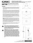
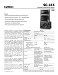
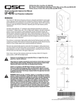
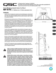
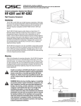
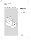
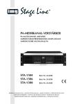
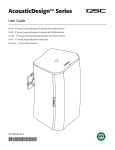
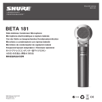
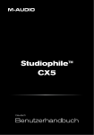
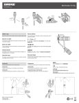
1675 MacArthur Blvd., Costa Mesa, CA, 92626 USA
Main Number (714) 754-6175 Sales & Marketing (714) 957-7100 or toll free (USA only) (800) 854-4079
Customer Service(714) 957-7150 or toll free (USA only) (800) 772-2834
Cinema Mid-High-Very High Loudspeaker System User Manual
MHV-1090
10” (254mm) mid, coax high- very high compression driver
Introduction
The MHV-1090 system provides the mid, high, and very high frequency components of
four-way screen channel loudspeaker system for high performance cinema applications. It was designed to operate with and be directly mounted on QSC’s cinema low
frequency enclosures.
The high frequency horn is a low-distortion waveguide providing highly articulate dialogue without the coloration associated with conventional horn loudspeakers. Both
horns feature broad horizontal and vertical coverage to ensure audio integrity is delivered to every seat in the auditorium. The driver assemblies are mounted on an adjustable pan and tilt bracket that has an integral aiming sight, simplifying installation.
30”
(762mm)
The MHV-1090 includes a driver protection and high-very high frequency crossover
network to assure reliable operation. DC blocking capacitors protect against DC or
low-frequency signals that could damage an unprotected driver. A 12 dB per octave
crossover seamlessly blends the high and very high frequency elements when operated in tri-amp mode. Outboard processing is required to form the crossover between
the low, mid, and high-very high frequency drivers.
Tri-amp or quad-amp operation is possible using a selector switch mounted on the
INPUTS connection panel. The tri-amp setting provides a built-in passive crossover
network between high and very high frequency drivers. Separate amplifiers and active
crossovers are required for the low, mid, high-very high frequency channels. Quadamp setting disables the internal high-very high frequency crossover and each driver
is driven independently by its own amplifier and active crossover; one each required
for the low, mid, high, and very high frequency drivers.
The MHV-1090 components come pre-assembled to reduce field assembly time. Three
bolts are all that are required to secure the assembly to the top of a QSC low frequency enclosure.
Install in accordance with QSC Audio Product’s instructions and a
licensed, professional engineer. Only use attachments, mounts,
accessories, or brackets specified by QSC Audio Products, Inc. Refer
all servicing to qualified personnel. Servicing is required when the
apparatus has been damaged in any way.
WARNING! Before placing, installing, rigging, or suspending any
speaker product, inspect all hardware, suspension, enclosures,
transducers, brackets and associated equipment for damage. Any
missing, corroded, deformed or non-load rated component could significantly reduce the strength of the installation, placement, or array.
Any such condition severely reduces the safety of the installation and
should be immediately corrected. Use only hardware which is rated
for the loading conditions of the installation and any possible shortterm unexpected overloading. Never exceed the rating of the hardware or equipment. Consult a licensed, professional engineer when
any doubt or questions arise regarding a physical equipment installation.
39”
(991mm)
20”
(508mm)
TD-000246-00-A
© Copyright 2007, QSC Audio Products, Inc.
QSC® is a registered trademark of QSC Audio Products, Inc.
“QSC” and the QSC logo are registered with the U.S. Patent and Trademark Office
*TD-000246-00*
Mounting
Attaching to Low Frequency Enclosure
The MHV-1090 attaches to the top of QSC low frequency enclosures with three 0.75” long 5/16”-18 TPI bolts. ensure the use of lock washers on all bolts.
The bolts and washers ship installed on the low frequency enclosure. We recommend the use of serviceable thread locking compound when installing the
bolts to prevent loosening due to vibration. Do not fully tighten the mounting hardware before aiming in the horizontal plane (see below).
Aiming
Aim the horn in the horizontal plane (pan) before tightening the three bolts securing the MHV-1090 to the low frequency enclosure. Adjust the vertical tilt
with the vertical adjustment bracket. The mid-high assembly is equipped with an aiming sight to assist in achieving desired coverage quickly and easily.
For typical applications, the aim point should be the center seat in the back row of the auditorium. If the cinema screen has already been installed, a flashlight placed at the desired aiming point can be seen through the screen perforations in a darkened auditorium.
Where the sight holes are located:
How to use the sights:
Aim point:
Settings and Connections
TRI-AMP / QUAD-AMP Operating Mode Selection
Set the operating mode selector switch to TRI-AMP or QUAD-AMP, depending on your screen channel signal processing and amplification set-up. The mid frequency driver will require connection to its
rear cover terminals, regardless of mode selection. The low frequency driver will also require its own,
separate connections. The only connection difference between tri-amp and quad-amp modes is in
quad-amp mode, the very high frequency signal will require connection to the terminals labeled VHF.
TRI-AMP-When set to TRI-AMP, the MHV-1090 input panel connections accept high frequency/very
high frequency signals on one set of inputs and uses an internal crossover network between the high
and very high frequency drivers.
QUAD-AMP- When set to QUAD-AMP, the MHV-1090 input panel accepts separate high and very
high frequency signals on two separate sets of inputs. The internal crossover network is bypassed and
only the protective circuitry for the high frequency and very high frequency driver remains. Each of the
driver’s signals must have the appropriate upstream signal processing.
•Do not connect amplifiers directly to the high/very high frequency coaxial driver
inputs!
• Always use the crossover INPUTS terminal strip for high and very high frequency
input(s)
•The mid frequency driver and the low frequency enclosure are connected directly
to their own separate amplifiers regardless of mode selector switch setting.
Mode selector switch set to
TRI-AMP and the required
HF/VHF connection:
HF/VHF
Mode selector switch set to
QUAD-AMP and the required separate HF and VHF connections:
VHF
HF
2
INPUTS Terminals
The MHV-1090 has barrier strip screw terminals that accept up to #10 AWG (5.3mm2) stranded loudspeaker wire. Observe proper polarity. Use the
largest wire size and shortest wire length for the application.
OUTPUTS Terminals
The OUTPUT terminals are factory-connected to the high and very high frequency drivers. These terminals should ONLY be connected to their respective driver. Do not connect signals to these terminals as all protection and equalization circuitry will be bypassed. They are not for daisy chaining the
signals to other drivers.
NOTE! Maintain proper loudspeaker connection polarity throughout the entire system for maximum performance. Do not apply
full range signal to the MHV-1090! There is a high/very high frequency passive crossover for tri-amp mode only. There is no
crossover connected when operating in quad-amp mode. All required signal processing must be done before the signal is
applied to the loudspeaker. Do not connect any signal to the upper sets of OUTPUT terminals.
TRI-AMP mode connections- Ensure the mode selector switch is set to TRI-AMP, connect the low frequency signal to the low frequency enclosure;
connect the mid frequency signal to the mid frequency driver; connect the high/very high frequency signal to the VHF/HF terminals on the INPUTS terminal strip.
Signal Processing
MHV-1090
HF/VHF MF
LF
Amplification
HF/VHF
MF
Amplification
LF
Low Frequency Enclosure
3
QUAD-AMP mode connections- Ensure the mode selector switch is set to QUAD-AMP, connect the low frequency signal to the low
frequency enclosure; connect the mid frequency signal to the mid frequency driver; connect the high frequency signal to the HF terminals on the INPUTS terminal strip; connect the very high frequency signal to the VHF terminals on the INPUTS terminal strip.
Signal Processing
MHV-1090
Amplification
VHF
HF
Amplification
MF
LF
Low Frequency Enclosure
4
VHF
HF MF LF
MHV-1090 Specifications (subject to change without notice)
Freq. Range
180 - 20k Hz (-6dB, full space)
Nominal Coverage
90° horizontal X +20 to -30° vertical (50° total, adjustable mount provides for vertical plane adjustments. The horizontal
plane can be adjusted by altering mounting position on the low frequency enclosure before tightening bolts.
DI:
9 dB (400 to 16k Hz average)
Q:
8 (400 to 16k Hz average)
Max. Output:, calculated
(1 meter, full space)
Mid frequency 135.5 dB SPL
Tri-amp mode: high frequency/very high frequency 138 dB SPL
Quad-amp mode: high frequency 138 dB SPL, very high frequency 135 dB SPL
Impedance:
Tri-amp mode: 8 ohms nominal, mid frequency and high/very high frequency
Quad-amp mode:8 ohms nominal, mid, high, and very high frequency
Maximum Input Power
(AES method, 2 hours)
Mid frequency: 275 W
Tri-amp mode: high/very high frequency 155 W (calculated, sum of high and very high frequency individual ratings)
Quad-amp mode:high frequency 85 W, very high frequency 70 W
Sensitivity
(1 Watt, 1 meter)
Mid frequency: 105 dB SPL
Tri-amp mode: high/very high frequency 110 dB SPL
Quad-amp mode:high frequency 110 dB SPL
very high frequency 110 dB SPL
Crossover Frequencies
Tri-amp mode: mid frequency 250 Hz or higher, high/very frequency 1.7 kHz, both 24 dB/octave
Quad-amp mode: mid frequency 250 Hz or higher, high frequency 1.7 kHz, very high frequency 6.0 kHz, all 24 dB/octave
Crossover Network
High frequency to very high frequency crossover at 7 kHz, 12 dB per octave, only in tri-amp mode. Quad-amp mode
switch setting removes crossover circuit from signal path, but leaves DC blocking capacitors in circuit.
Connectors
Mid frequency driver: barrier strip screw terminals on mid frequency driver accept up to #10 AWG stranded wire.
High frequency, very high frequency drivers: barrier strip screw terminals accept up to #10 AWG stranded wire
Tri-amp mode connect high frequency/very high frequency program only to VHF/HF INPUTS terminals
Quad-amp mode connect high frequency program to HF INPUTS terminals and connect very high frequency
program to VHF INPUTS terminals.
Transducers
Mid frequency: 10" high efficiency mid-range, phase-ring loaded
High frequency: 1.5" exit, 3.5" voice coil polyester diaphragm coaxial compression driver
Very High frequency: 1.5" exit, 1.75" voice coil polyester diaphragm coaxial compression driver
Mounting Hardware:
Attaches to top of QSC’s low frequency cinema enclosures using three 5/16”-18 x 3/4” long bolts (supplied on low frequency enclosure)
Size
39” high x 30” wide x 20” deep (991 x 762 x 508mm)
Weight
73.5 lb. (33 kg) net
5
SPL (dB, normalized)
MHV-1090 SPL vs. Frequency, Tri-amp, No Screen
mid
high/very high
Frequency (Hz)
SPL (dB, normalized)
MHV-1090 SPL vs. Frequency, Quad-amp, No Screen
mid
high
very high
Frequency (Hz)
6
MHV-1090 SPL vs. Frequency, X-curve, Tri-amp, With and Without Screen
without screen
X-curve +3 dB
SPL (dB, normalized)
X-curve -3 dB
with screen
Frequency (Hz)
MHV-1090 SPL vs. Frequency, X-curve, Quad-amp, With and Without Screen
X-curve +3 dB
without screen
X-curve -3 dB
SPL (dB, normalized)
with screen
Frequency (Hz)
7
Warranty (USA only; other countries, see your dealer or distributor)
Disclaimer
QSC Audio Products, Inc. is not liable for any damage to amplifiers, or any other equipment that is caused by negligence or
improper installation and/or use of this loudspeaker product.
QSC Audio Products 3 Year Limited Warranty
QSC Audio Products, Inc. (“QSC”) guarantees its products to be free from defective material and / or workmanship for a period
of three (3) years from date of sale, and will replace defective parts and repair malfunctioning products under this warranty
when the defect occurs under normal installation and use - provided the unit is returned to our factory or one of our authorized
service stations via pre-paid transportation with a copy of proof of purchase (i.e., sales receipt). This warranty provides that
the examination of the return product must indicate, in our judgment, a manufacturing defect. This warranty does not extend
to any product which has been subjected to misuse, neglect, accident, improper installation, or where the date code has been
removed or defaced. QSC shall not be liable for incidental and/or consequential damages. This warranty gives you specific
legal rights. This limited warranty is freely transferable during the term of the warranty period.
Customer may have additional rights, which vary from state to state.
In the event that this product was manufactured for export and sale outside of the United States or its territories, then this limited warranty shall not apply. Removal of the serial number on this product, or purchase of this product from an unauthorized
dealer, will void this limited warranty. Periodically, this warranty is updated. To obtain the most recent version of QSC’s warranty statement, please visit www.qscaudio.com. Contact us at 800-854-4079 or visit our website at www.qscaudio.com.
Contacting QSC Audio Products
Mailing address:QSC Audio Products, Inc.
1675 MacArthur Boulevard
Costa Mesa, CA 92626-1468 USA
Telephone Numbers:
Main Number (714) 754-6175
Sales & Marketing (714) 957-7100 or toll free (USA only) (800) 854-4079
Customer Service(714) 957-7150 or toll free (USA only) (800) 772-2834
Facsimile Numbers:
Sales & Marketing Fax(714) 754-6174
Customer Service Fax(714) 754-6173
World Wide Web:www.qscaudio.com
E-mail:[email protected]
[email protected]
QSC Audio Products, Inc. 1675 MacArthur Boulevard Costa Mesa, California 92626 USA
©2007 “QSC” and the QSC logo are registered with the U.S. Patent and Trademark Office.
1675 MacArthur Blvd., Costa Mesa, CA, 92626 USA
Main Number (714) 754-6175 Sales & Marketing (714) 957-7100 or toll free (USA only) (800) 854-4079
Customer Service (714) 957-7150 or toll free (USA only) (800) 772-2834
Cinema Loudspeaker Systems User Manual
LF-3215 Low Frequency Loudspeaker
Introduction
The LF-3215 dual 15” (381mm) low frequency enclosure is designed specifically for cinema
applications. Meeting cinema requirements for extended low frequency response differentiates the LF-3215 from more conventional “rock-and-roll” woofer systems. The LF-3215 covers the frequency range from 32 Hertz to 1500 Hertz, depending upon the high frequency
system requirements. With its tight spacing between woofers, the LF-3215 offers improved
coupling and keeps coverage angles wide over a greater frequency range than more widely
spaced designs.
The 300 watt, 15” transducers are well suited for cinema use. They feature 3” (76mm) voice
coils, 120 oz.(3.4kg) ceramic magnets, and vented pole pieces to ensure cool operation.
Cooler temperatures increase transducer lifespan and decrease the problem of power compression at high power levels. The suspension and voice coil of each transducer have been
designed to provide low distortion and high impact bass at high power levels.
The enclosure is constructed of high quality medium density fiberboard panels with stiffening braces on all panels and features separate woofer chambers. This prevents over-excursion of a transducer caused by improper box loading in the rare event of a transducer failure.
The eight stiffening braces reduce panel resonance.
Mounting points for midhigh or high frequency
system
Both internal and external port openings are fully radiused ensuring smooth air flow at high
power. This prevents audible port turbulence noise.
With symmetrical port loading, bass ports are evenly spaced on each side of the transducers, making internal pressure more uniform across the back surface of the transducer. This
prevents the cone from being displaced to one side or another by unbalanced forces, reducing the chance of driving the voice coil out of the center of the gap at high power levels.
Three T-nuts in the top of the enclosure provide easy mounting of QSC’s HF-63 high frequency system, or MH-1063 mid-high frequency system.
Enclosure is not designed to be suspended, flown, or rigged. Do not suspend, fly, or rig this enclosure.
This product is capable of producing sound pressure levels that can permanently damage human hearing. Always keep sound pressure levels in the
listening area below levels that can damage human hearing.
Install in accordance with QSC Audio Product’s instructions and a
licensed, professional engineer. Only use attachments, mounts, accessories, or brackets specified by QSC Audio Products, Inc. Refer all servicing
to qualified personnel. Servicing is required when the apparatus has been
damaged in any way.
WARNING! Before placing, installing, rigging, or suspending any speaker
product, inspect all hardware, suspension, cabinets, transducers, brackets
and associated equipment for damage. Any missing, corroded, deformed or
non-load rated component could significantly reduce the strength of the
installation, placement, or array. Any such condition severely reduces the
safety of the installation and should be immediately corrected. Use only
hardware which is rated for the loading conditions of the installation and
any possible short-term unexpected overloading. Never exceed the rating
of the hardware or equipment. Consult a licensed, professional engineer
when any doubt or questions arise regarding a physical equipment installation.
*TD-000173-00*
TD-000173-00 rev.C
© Copyright 2004, QSC Audio Products, Inc.
QSC® is a registered trademark of QSC Audio Products, Inc.
“QSC” and the QSC logo are registered with the U.S. Patent and Trademark Office
Connections
Normal Connection
The LF-3215 has barrier strip screw terminals for connection. The terminals accept
up to #10 AWG (5.3mm2) stranded loudspeaker wiring. Use the largest wire size
and shortest wire length possible for the
application. Observe the polarity markings
and keep polarity consistent throughout
the system for best performance.
Normal Connection Example:
Parallel Connection of Second LF-3215
The terminals marker SPK2 may be used to
connect another LF-3215 in parallel. Connect the wires as shown in the illustration,
at right. Note: If the LF-3215’s internal wiring has been modified in any way, this may
not function. If this is the case, remove the
terminal cup and verify the presence of the
factory yellow jumper and blue jumper
wires; remedy as required or have the
loudspeaker serviced.
Parallel Connection Example:
Individual Transducer Connection
(requires modification)
The transducers are wired in parallel
inside the enclosure. If individual transducer connection is required, remove the
terminal cup and remove the yellow and
the blue jumper wires that are connected
between the SPK1 and SPK2 terminals.
Replace the terminal cup and mark the
enclosure with a note of the modification.
Amplifier capable of
driving 4 ohm loads
Amplifier capable of
driving 2 ohm loads
Individual Transducer
Connection Example:
CAUTION! Requires
removal of terminal
cup and removing
both the yellow and
the blue jumper
wires that connect
the SPK1 and SPK2
terminals.
LF-3215 Specifications (subject to change without notice)
Frequency Range:
32 - 1500 Hertz (-6dB)
28 - 3300 Hertz useable range (-10dB)
Nominal Coverage:
100° horizontal X 55° vertical at 600 Hertz
Maximum Output:
132.5 dB SPL calculated peak, 1 meter, half space, at rated rms power with 6 dB crest factor pink noise input, 25 - 250 Hertz.
126.5 dBA SPL calculated maximum continuous, 1 meter. The dBA scale is typically used to identify sound sources
which can cause permanent hearing loss.
Impedance:
4 ohms nominal
4.1 ohms minimum, 180 Hertz
55 ohms maximum, 21 Hertz
Maximum Input Power:
600 watts rms (8 hours of 6 dB crest factor pink noise, 40 - 400 Hertz)
750 watts rms (2 hours of 6 dB crest factor pink noise, 40 - 400 Hertz)
Recommended amplifier power capability- 1200 watts rms maximum into 4 ohms (per LF-3215)
Sensitivity:
98.5 dB half space, 97.5 dB full space, 35 - 1000 Hertz, 1 watt, 1 meter
Recommended Processing:
Subsonic filter below 30 Hertz, >18 dB per octave, maximum recommended crossover frequency is 1000 Hertz. QSC
DSP configurations are available at www.qscaudio.com. Parameters for alternative processing hardware are available
upon request.
Connectors:
Barrier strip screw terminals accept up to #10 AWG stranded wire. Four terminals: (two INPUT and two PARALLEL
OUT). Transducers are internally wired in parallel. For independent transducer connection, remove blue jumper wire
and yellow jumper wire on internal-side of terminal cup and mark enclosure accordingly.
Transducers:
Two 15” (381mm) high efficiency low frequency transducers featuring vented 3” (76mm) copper voice coils on Kapton®
formers. High excursion/low distortion design, with extremely high power handling, and low thermal and port compression.
Enclosure:
Quasi B4 alignment, ported enclosure with fully flared ports, low turbulence symmetrical port design, tuned to 36
Hertz, constructed of medium density fibreboard and heavily braced. Features vandal resistant woofer mounting bolts.
Size:
30” wide X 35” high X 20” deep (762 mm X 889 mm X 508 mm)
Weight:
195 lbs. shipping, 172 lbs. net (88/78 kg.)
SPL and Impedance vs. Frequency
SPL 2pi
SPL (dB)
Impedance (ohms)
SPL 4pi
Impedance
Frequency (Hertz)
Warranty (USA only; other countries, see your dealer or distributor)
Disclaimer
QSC Audio Products, Inc. is not liable for any damage to amplifiers, or any other equipment that is caused by negligence or
improper installation and/or use of this loudspeaker product.
QSC Audio Products 3 Year Limited Warranty
QSC Audio Products, Inc. (“QSC”) guarantees its products to be free from defective material and / or workmanship for a period
of three (3) years from date of sale, and will replace defective parts and repair malfunctioning products under this warranty
when the defect occurs under normal installation and use - provided the unit is returned to our factory or one of our authorized
service stations via pre-paid transportation with a copy of proof of purchase (i.e., sales receipt). This warranty provides that
the examination of the return product must indicate, in our judgment, a manufacturing defect. This warranty does not extend
to any product which has been subjected to misuse, neglect, accident, improper installation, or where the date code has been
removed or defaced. QSC shall not be liable for incidental and/or consequential damages. This warranty gives you specific
legal rights. This limited warranty is freely transferable during the term of the warranty period.
Customer may have additional rights, which vary from state to state.
In the event that this product was manufactured for export and sale outside of the United States or its territories, then this limited warranty shall not apply. Removal of the serial number on this product, or purchase of this product from an unauthorized
dealer, will void this limited warranty. Periodically, this warranty is updated. To obtain the most recent version of QSC’s warranty statement, please visit www.qscaudio.com. Contact us at 800-854-4079 or visit our website at www.qscaudio.com.
Contacting QSC Audio Products
Mailing address:QSC Audio Products, Inc.
1675 MacArthur Boulevard
Costa Mesa, CA 92626-1468 USA
Telephone Numbers:
Main Number (714) 754-6175
Sales & Marketing (714) 957-7100 or toll free (USA only) (800) 854-4079
Customer Service(714) 957-7150 or toll free (USA only) (800) 772-2834
Facsimile Numbers:
Sales & Marketing Fax(714) 754-6174
Customer Service Fax(714) 754-6173
World Wide Web:www.qscaudio.com
E-mail:[email protected]
[email protected]
QSC Audio Products, Inc. 1675 MacArthur Boulevard Costa Mesa, California 92626 USA
©2004 “QSC” and the QSC logo are registered with the U.S. Patent and Trademark Office.
Kapton® is a registered trademark of E.I. du Pont de Nemours and Company.
Manual del usuario de los sistemas de altavoces para salas de cine
Altavoz de baja frecuencia
LF-3215
Introducción
La caja doble de baja frecuencia de 15” (381 mm) del altavoz LF-3215 está diseñada específicamente para aplicaciones cinematográficas. El cumplimiento de los requisitos de las aplicaciones cinematográficas referentes a una respuesta extendida de baja frecuencia, es lo
que distingue al altavoz LF-3215 de otros sistemas woofer tipo “rock-and-roll” más convencionales. El altavoz LF-3215 cubre un intervalo de frecuencia de 32 Hertzios a 1500 Hertzios,
dependiendo de los requisitos del sistema de alta frecuencia. Con su espacio estrecho entre
los woofers, el LF-3215 ofrece un mejora en el acoplamiento y mantiene la amplitud de los
ángulos de cobertura sobre un mayor intervalo de frecuencia en comparación con diseños de
espacio más grande.
Los transductores de 300 vatios y 15” son apropiados para uso en salas de cine. Cuentan
con bobinas de voz de 3” (76 mm), imanes cerámicos de 120 onzas (3.4 kg) y polos multiventilados para asegurar una operación fría. Las temperaturas más frías aumentan la vida útil
del transductor y disminuyen el problema de compresión de la potencia a niveles altos de
potencia. La suspensión y la bobina de voz de cada transductor se han diseñado para brindar
una baja distorsión y graves de alto impacto a altos niveles de potencia.
Puntos de montaje para el
sistema de alta frecuencia o el
sistema de frecuencia media
alta
La caja está construida de paneles de cartón duro mediano de alta calidad con soportes de
refuerzo en todos los paneles, y cuenta con cámaras separadas para los woofers. Esto previene la excursión excesiva de un transductor causada por la carga inadecuada de la caja, en
el raro evento de falla del transductor. Los ocho soportes de refuerzo reducen la resonancia
en el panel.
Ambas aberturas del puerto, la interna y la externa, están totalmente redondeadas, asegurando un flujo de aire uniforme a alta potencia. Esto evita ruido de turbulencia audible en el
puerto.
Con la carga simétrica de los puertos, los puertos de graves están igualmente separados a
cada lado de los transductores, haciendo que la presión interna sea más uniforme a través
de la superficie posterior del transductor. Esto evita que el cono sea desplazado de un lado a
otro por fuerzas no equilibradas, reduciendo la probabilidad de impulsar la bobina de voz
fuera del centro del espacio a altos niveles de potencia.
Tres tuercas en T en la parte superior de la caja permiten el montaje fácil del sistema de alta
frecuencia HF-63 o del sistema de frecuencia media alta MH-1063, ambos de QSC.
La caja no esta diseñada para montarse suspendida, en voladizo ni sobre arneses.
No suspenda esta caja, no la monte en voladizo ni sobre arneses.
Este producto es capaz de producir niveles de presión del sonido que pueden
causar daños permanentes al oído humano. Siempre mantenga los niveles de
presión del sonido en un área de audición con un nivel menor que el que provoca
daños al oído humano.
Instale de acuerdo con las instrucciones de QSC Audio Products y de un ingeniero
profesional con la debida licencia. Sólo use piezas, montajes, accesorios y soportes especificados por QSC Audio Products, Inc. Refiera todo el servicio a personal
calificado. Cuando el aparato haya sido dañado de alguna manera, es necesario
proporcionarle servicio.
¡ADVERTENCIA! Antes de colocar, instalar, montar o suspender cualquier producto
de altavoz, inspeccione todo el equipo físico, la suspensión, los armarios, los transductores, los soportes y el equipo asociado para detectar la existencia de daños.
Cualquier componente faltante, corroído, deformado, o sin carga nominal podría
reducir significativamente la resistencia de la instalación, la colocación o la configuración. Cualquier condición de este tipo reduce gravemente la seguridad de la
instalación y debe corregirse de inmediato. Use sólo herraje que esté clasificado
para las condiciones de carga de la instalación y cualquier posible carga excesiva
a corto plazo inesperada. Nunca exceda el valor nominal del equipo físico ni del
dispositivo. Consulte a un ingeniero profesional con la debida licencia cuando surjan dudas o preguntas referentes a la instalación física del equipo.
TD-000173-00 rev. C
© Derechos de autor 2004, QSC Audio Products, Inc.
QSC® es una marca comercial registrada de QSC Audio Products, Inc.
“QSC” y el logotipo de QSC están registrados con la Oficina de Patentes y Marcas
Comerciales de los Estados Unidos
Conexiones
Conexión normal
El altavoz LF-3215 tiene terminales de tornillo de barra protectora para su conexión.
Los terminales aceptan cableado trenzado
de hasta #10 AWG (5.3 mm2) para altavoces. Use el alambre de calibre más
grande y de longitud más corta posible
para la aplicación. Observe las marcas de
polaridad y mantenga la polaridad uniforme en todo el sistema para permitir el
mejor rendimiento.
Ejemplo de una conexión normal:
Amplificador con capacidad de accionamiento de cargas de 4 ohmios
Ejemplo de conexión en paralelo:
Conexión en paralelo de un segundo LF3215
Los terminales marcados SPK2 se pueden
usar para conectar en paralelo otro altavoz
LF-3215. Conecte los cables como se
muestra en la ilustración, a la derecha.
Nota: si el cableado interno de LF-3215 se
ha modificado de alguna manera, es
posible que no funcione. En este caso,
quite la cúpula del terminal y verifique la
presencia de alambres amarillos y azules
de puentes instalados en fábrica; corrija el
problema según se requiera, o solicite que
den servicio al altavoz.
Amplificador con capacidad de
accionamiento de cargas de 2 ohmios
Ejemplo de la conexión
de un transductor individual:
Conexión del transductor individual
(requiere modificación)
Los transductores están conectados en
paralelo dentro de la caja. Si se requiere la
conexión del transductor individual, quite
la cúpula del terminal y quite los alambres
amarillo y azul del puente que están
conectados entre los terminales SPK1 y
SPK2. Vuelva a colocar la cúpula del terminal y marque la caja con una nota que
indique la modificación.
¡PRECAUCIÓN!
Requiere desmontar
la cúpula del terminal y los alambres
amarillo y azul que
conectan los terminales SPK1 y SPK2.
Especificaciones del sistema LF-3215 (sujetas a cambio sin previo aviso)
Intervalo de frecuencias:
32 -1500 Hertzios (-6dB)
Intervalo utilizable de 28 -3300 Hertzios (-10 dB)
Cobertura nominal:
100° horizontal X 55° vertical a 600 Hertzios
Salida máxima:
Pico calculado de SPL: 132.5 dB, 1 metro, medio espacio, a una potencia rms nominal con entrada de ruido rosa con factor de
cresta de 6 dB, 25 - 250 Hertzios.
Máximo calculado continuo de SPL: 126.5 dBA, 1 metro. La escala de dBA típicamente se usa para identificar
fuentes de sonido que pueden causar pérdida auditiva permanente.
Impedancia:
4 ohmios, nominal
4.1 ohmios mínimo, 180 Hertzios
55 ohmios máximo, 21 Hertzios
Potencia máxima
de entrada:
600 vatios rms (8 horas de ruido rosa con factor de cresta de 6 dB, 40 -400 Hertzios)
750 vatios rms (2 horas de ruido rosa con factor de cresta de 6 dB, 40 -400 Hertzios)
Capacidad recomendada de potencia del amplificador: 1200 vatios rms como máximo en 4 ohmios (por LF-3215)
Sensibilidad:
98.5 dB medio espacio, 97.5 dB espacio completo, 35 - 1000 Hertzios, 1 vatio, 1 metro
Procesamiento
recomendado:
Filtro subsónico menor de 30 Hertzios, >18 dB por octava, la frecuencia máxima de cruce recomendada es de
1000 Hertzios. Las configuraciones DSP de QSC están disponibles en www.qscaudio.com. Los parámetros para el
herraje de procesamiento alternativo están disponibles si así se solicitan.
Conectores:
Los terminales de tornillo de barra protectora aceptan alambre trenzado de hasta #10 AWG . Cuatro terminales:
(dos de ENTRADA y dos de SALIDA PARALELA). Los transductores están cableados internamente en paralelo.
Para la conexión de un transductor independiente, quite los alambres azul y amarillo de los puentes que se
encuentran en el lado interno de la cúpula del terminal y marque la caja de acuerdo con esto.
Transductores:
Dos transductores de baja frecuencia de alta eficiencia, de 15” (381 mm), con bobinas de voz de cobre de 3”
(76mm) ventiladas, en soportes de Kapton®. Diseño de alta excursión/baja deformación, con un manejo de
potencia extremadamente alta, y baja compresión térmica y de puerto.
Caja:
Alineación Quasi B4, caja con puertos totalmente abocinados, diseño de puerto simétrico de baja turbulencia,
afinado a 36 Hertzios, construido de cartón duro de media densidad y fuertemente soportado. Tiene pernos de
montaje del woofer resistentes al vandalismo.
Tamaño:
30” de ancho X 35” de alto X 20” de profundidad (762 mm X 889 mm X 508 mm)
Peso:
195 libras envío, 172 libras neto (88/78 kg.)
SPL e impedancia en función de la frecuencia
SPL (dB)
SPL 4pi
Impedancia
Frecuencia (hertzios)
Impedancia (ohmios)
SPL 2pi
Garantía (sólo para EE.UU.; para otros países, consulte con su vendedor o distribuidor)
Renuncia de responsabilidad
QSC Audio Products, Inc. no es responsable por ningún daño a los amplificadores, ni a ningún otro equipo que sea causado por
negligencia o instalación y/o uso inadecuado de este altavoz.
Garantía limitada de 3 años de QSC Audio Products
QSC Audio Products, Inc. (“QSC”) garantiza que sus productos estarán libres de materiales y/o mano de obra defectuosos por
un periodo de tres (3) años a partir de la fecha de la venta, y reemplazará las piezas defectuosas y reparará los productos que
funcionen mal bajo esta garantía cuando el defecto ocurra bajo condiciones normales de instalación y uso, siempre y cuando
la unidad se devuelva a nuestra fábrica o a una de nuestras estaciones autorizadas de servicio mediante transportación prepagada con una copia del comprobante de compra (por ejemplo, el recibo de la compra). Esta garantía requiere que el examen
del producto devuelto indique, en nuestra opinión, un defecto de fabricación. Esta garantía no se extiende a ningún producto
que hubiera estado sometido a uso indebido, negligencia, accidente, instalación incorrecta, o en el que se hubiera quitado o
modificado el código de la fecha. QSC tampoco será responsable por daños incidentales y/o emergentes. Esta garantía le
otorga derechos legales específicos. Esta garantía limitada es libremente transferible durante el período de la misma.
El cliente podría gozar de derechos adicionales, que podrían variar de un estado a otro.
En caso de que este producto fuera fabricado para exportación y venta fuera de los Estados Unidos o sus territorios, entonces
no será aplicable esta garantía limitada. La eliminación del número de serie en este producto, o la compra de este producto de
un distribuidor no autorizado, anularán esta garantía limitada. Esta garantía se actualiza periódicamente. Para obtener la versión más reciente de la declaración de la garantía de QSC, por favor visite www.qscaudio.com. Comuníquese con nosotros al
800-854-4079 o visite nuestro sitio en Internet en www.qscaudio.com.
Cómo comunicarse con QSC Audio Products
Dirección postal:QSC Audio Products, Inc.
1675 MacArthur Boulevard
Costa Mesa, CA 92626-1468 EE.UU.
Números de teléfono:
Número principal +1 (714) 754-6175
Ventas y comercialización +1 (714) 957-7100 o gratis (sólo EE.UU.) +1 (800) 854-4079
Servicio al cliente +1 (714) 957-7150 o gratis (sólo EE.UU.) +1 (800) 772-2834
Números de fax:
Fax de ventas y comercialización +1 (714) 754-6174
Fax de servicio al cliente +1 (714) 754-6173
World Wide Web:www.qscaudio.com
Correo electrónico:[email protected]
[email protected]
QSC Audio Products, Inc. 1675 MacArthur Boulevard Costa Mesa, California 92626 EE.UU.
©2004, “QSC” y el logo QSC están registrados con la Oficina de Patentes y Marcas Comerciales de EE.UU.
Kapton® es una marca comercial registrada de E.I. du Pont de Nemours and Company.
1675 MacArthur Blvd., Costa Mesa, CA 92626
Téléphone (standard) +1 (714) 754-6175 Ventes et Marketing +1 (714) 957-7100
ou +1 (800) 854-4079 (numéro vert valable aux États-Unis seulement)
Service clientèle +1 (714) 957-7150 ou numéro vert (États-Unis seulement) +1 (800) 772-2834
Manuel d'utilisation de systèmes de haut-parleurs de cinéma
Haut-parleur basse fréquence
LF-3215
Introduction
L'enceinte basse fréquence double de 381 mm LF-3215 a été tout spécialement conçue pour
les applications en salle de cinéma. Les exigences des cinémas en matière de réponse
longue durée basse fréquence différencient le LF-3215 des systèmes de haut-parleurs de
graves « rock-and-roll » plus conventionnels. Le LF-3215 couvre la plage de fréquence de
32 à 1500 Hz, selon les exigences de haute fréquence du système. Avec peu d'espace entre
les haut-parleurs de graves, le LF-3215 améliore le couplage et permet des angles de
couverture larges sur une plus grande plage de fréquences que les modèles plus espacés.
Les transducteurs de 300 W et 38 cm sont bien adaptés à une utilisation dans les salles de
cinéma. Ils ont des bobines mobiles de 76 mm, des aimants en céramique de 3,4 kg et des
pôles à évents pour empêcher la surchauffe. Les températures inférieures augmentent la
durée de vie des transducteurs et diminuent le problème de compression de puissance à de
hauts niveaux de puissance. La suspension et la bobine mobile de chaque transducteur
visent à produire une faible distorsion et des graves à fort impact à haute puissance.
Points de fixation d'un système
haute fréquence ou de hauteur
moyenne
L'enceinte est faite de panneaux de fibres de densité moyenne et de haute qualité avec des
renforts sur tous les panneaux et elle a des caissons de graves distincts. Ce principe
empêche le dépassement de course d'un transducteur qui serait causé par le chargement
inadapté du boîtier dans l'éventualité rare d'une panne de transducteur. Les huit renforts
réduisent la résonance des panneaux.
Les ouvertures internes et externes des ports sont entièrement arrondies, garantissant la
circulation d'air uniforme à haute puissance, ce qui empêche les interférences sonores.
Grâce au chargement symétrique des ports (SPL), les ports à basses sont équidistants de
part et d'autre des transducteurs, ce qui répartit uniformément la pression interne à travers
la surface arrière du transducteur. Ceci empêche le déplacement du cône d'un côté ou de
l'autre par des forces déséquilibrées, ce qui réduit le risque d'excentrage de la bobine
mobile à haute puissance.
Trois écrous en T sur le dessus de l'enceinte facilitent la fixation du système haute
fréquence HF-63 ou du système sonore de hauteur moyenne MH-1063 de QSC.
L'enceinte n'a pas été conçue pour être suspendue, balancée ou montée. La
suspension, le balancement ou le montage de l'enceinte sont interdits.
Ce produit est capable de produire des niveaux de pression sonore
susceptibles d'endommager l'ouïe de manière irréversible. Toujours maintenir
les niveaux de pression sonore dans la zone d'écoute en deçà de niveaux
susceptibles de compromettre l'ouïe.
Installer conformément aux instructions de QSC Audio Products et d'un
technicien professionnel diplômé. Utiliser uniquement des fixations, supports,
accessoires ou équerres spécifiés par QSC Audio Products. Confier toutes les
réparations à un personnel qualifié. Une réparation ou maintenance est requise
lorsque l'appareil a été endommagé d'une manière quelconque.
AVERTISSEMENT ! Avant de placer, installer, monter ou suspendre un hautparleur, inspecter l'état de toute la visserie, du matériel de suspension, des
armoires, des transducteurs, des supports et du matériel associé. Tout
composant manquant, corrodé, déformé ou non adapté à la charge risque de
réduire sensiblement la solidité de l'installation, sa mise en place ou sa portée.
Une telle condition réduit sensiblement la sécurité de l'installation et doit être
immédiatement corrigée. Utiliser uniquement du matériel de montage prévu
pour les conditions de charge de l'installation et toute surcharge éventuelle à
court terme imprévue. Ne jamais dépasser les spécifications nominales du
matériel de montage ou de l'équipement. Consulter un technicien
professionnel diplômé en cas de doute ou de question concernant l'installation
physique de l'équipement.
TD-000173-00 rév. C
© Copyright 2004, QSC Audio Products, Inc.
QSC® est une marque déposée de QSC Audio Products, Inc.
QSC et le logo QSC sont des marques déposées auprès de l'U.S. Patent and
Trademark Office.
Branchements
Branchement normal
Le branchement du LF-3215 se fait à partir
de bornes vissables de bornier à cloisons.
Les bornes acceptent des câbles de hautparleurs toronnés pouvant atteindre
#10 AWG (5,3 mm2). Utiliser des
conducteurs de calibre maximal et de
longueur minimale pour l'application.
Observer les repères de polarité et
maintenir une polarité constante à travers
le système pour une meilleure
performance.
Exemple de branchement
normal :
Amplificateur capable
de piloter des charges
de 4 ohms
Exemple de branchement en
parallèle :
Branchement en parallèle d'un second
LF-3215
Le marqueur de bornes SPK2 peut servir au
branchement d'un autre LF-3215 en
parallèle. Brancher les conducteurs
comme indiqué sur l'illustration, à droite.
Remarque : Si le câblage interne du
LF-3215 a été modifié d'une manière
quelconque, il est possible que ce
branchement ne donne aucun résultat.
Dans ce cas, retirer la cupule de la borne
et vérifier la présence des connexions
temporaires jaune et bleue ; corriger le
problème ou faire réparer le haut-parleur.
Amplificateur capable de
piloter des charges de 2 ohms
Transducteur individuel
Exemple de branchement :
Branchement individuel des
transducteurs (modification obligatoire)
Les transducteurs sont câblés en parallèle
à l'intérieur de l'enceinte. Si un
branchement individuel est requis, retirer
la cupule de la borne et retirer les
connexions temporaires jaune et bleue
entre les bornes SPK1 et SPK2. Remettre
la cupule sur la borne et apposer sur
l'enceinte une note indiquant la
modification.
ATTENTION ! Exige
le retrait de la cupule
sur la borne et la
coupe des
connexions
temporaires jaune et
bleu entre les bornes
SPK1 et SPK2.
Caractéristiques techniques du LF-3215 (sujettes à modification sans préavis)
Plage de fréquence :
32 à 1 500 Hz (-6 dB)
28 à 3 300 Hz (plage utile) (-10 dB)
Couverture nominale :
100° horizontal x 55° vertical à 600 Hz
Sortie maximale :
Niveau de pression sonore maximal calculé de 132,5 dB, à 1 m, demi-espacement, à la puissance nominale efficace avec 6 dB entrée de
bruit rose de facteur de crête, 25 à 250 Hz.
Niveau de pression sonore maximal calculé continu de 126,5 dBA, à 1 m. L'échelle de dBA sert généralement à identifier les
sources sonores susceptibles de causer une surdité permanente.
Impédance :
4 ohms, nominale
4,1 ohms minimale, 160 Hz
55 ohms maximale, 21 Hz
Puissance d'entrée maximale : 600 W (efficace) (8 heures de bruit rose de facteur de crête 6 dB, 40 à 400 Hz)
750 W (efficace) (2 heures de bruit rose de facteur de crête 6 dB, 40 à 400 Hz)
Capacité de puissance d'amplificateur recommandée - 1 200 W (efficace) maximum dans 4 ohms (conformément au modèle
LF-3215)
Sensibilité :
98,5 dB demi-espacement, 97,5 dB espacement total, 35 à 1000 Hz, 1 W, 1 m
Traitement recommandé :
Filtre subsonique inférieur à 30 Hz, >18 dB par octave ; fréquence de filtre passif maximale recommandée : 1 000 Hz. Les
configurations des processeurs de champs sonores numériques QSC sont disponibles sur le site www.qscaudio.com. Les
paramètres concernant d'autres matériels de traitement sont disponibles sur demande.
Connecteurs :
Les bornes acceptent des câbles de haut-parleurs toronnés pouvant atteindre #10 AWG. Quatre bornes : (deux d'entrée et
deux de sortie parallèle). Les transducteurs sont câblés à l'intérieur en parallèle. Pour le branchement indépendant d'un
transducteur, retirer la connexion temporaire bleue et la connexion temporaire jaune de l'intérieur de la cupule de borne et
laisser une note sur l'enceinte signalant cette modification.
Transducteurs :
Deux transducteurs basse fréquence ultra-efficaces de 381 mm avec bobines mobiles en cuivre de 76 mm à évents sur
formes Kapton®. Conception du type excursion élevée/faible distorsion, qui permet le traitement d'une puissance
extrêmement élevée, et réduit la chauffe et la compression des ports.
Enceinte :
Enceinte résonnante à alignement quasi B4 avec ports entièrement arrondis ; conception symétrique des ports à faible
turbulence ; réglée à 36 Hz, en panneaux de fibres de densité moyenne et fortement renforcé. Possède des boulons de
fixation sur les haut-parleurs de graves résistants aux vandales.
Dimensions :
762 mm (largeur) x 889 mm (hauteur) x 508 mm (épaisseur)
Poids brut :
88 kg Poids net : 78 kg
SPL et impédance par rapport à la fréquence
SPL 2pi
SPL (dB)
Impédance (ohms)
SPL 4pi
Impédance
Fréquence (Hz)
Garantie (États-Unis seulement ; dans les autres pays, consulter le revendeur ou le distributeur)
Avis de non-responsabilité
QSC Audio Products, Inc. n'est pas responsable des dommages subis par les amplificateurs ou tout autre équipement causé
par un acte de négligence ou une installation impropre et/ou l'utilisation de ce haut-parleur.
QSC Audio Products - Garantie limitée de 3 ans
QSC Audio Products, Inc. (« QSC ») garantit que ses produits sont dépourvus de tout vice de fabrication et/ou de matériel
pendant une période de trois (3) ans à partir de la date de vente et remplacera les pièces défectueuses et réparera les produits
qui fonctionnent mal dans le cadre de cette garantie si le défaut survient dans des conditions normales d'installation et
d'utilisation - à condition que l'appareil soit retourné à l'usine ou à l'un de nos centres de réparation agréés en port prépayé,
accompagné d'un justificatif d'achat (facture, par ex.). Cette garantie prévoit que l'examen du produit retourné doit indiquer,
selon notre jugement, un défaut de fabrication. Cette garantie ne s'étend à aucun produit qui a été soumis à une utilisation
abusive, un acte de négligence, un accident, une installation incorrecte ou un produit dont le code-date a été retiré ou effacé.
QSC ne pourra être tenue pour responsable de dommages accessoires et/ou indirects. Cette garantie vous accorde des droits
spécifiques. Cette garantie limitée est librement cessible durant sa période de validité.
Le client pourra bénéficier d'autres droits, variables d'une juridiction à l'autre.
Si ce produit a été fabriqué pour une exportation et une vente en dehors des États-Unis ou de ses territoires, cette garantie
limitée ne s'appliquera pas. Le retrait du numéro de série sur ce produit ou l'achat de ce produit auprès d'un revendeur non
agréé annulera cette garantie limitée. Cette garantie est régulièrement mise à jour. Pour obtenir la toute dernière version de la
garantie de QSC, rendez-vous sur le site www.qscaudio.com. Contactez-nous au 800-854-4079 ou visitez notre site Web
www.qscaudio.com.
Pour contacter QSC Audio Products
Adresse postale :QSC Audio Products, Inc.
1675 MacArthur Boulevard
Costa Mesa, CA 92626-1468, États-Unis
Téléphone :
Standard +1 (714) 754-6175
Ventes & Marketing +1 (714) 957-7100 ou numéro vert (États-Unis seulement) +1 (800) 854-4079
Service clientèle +1 (714) 957-7150 ou numéro vert (États-Unis seulement) +1 (800) 772-2834
Télécopieur :
Ventes & Marketing Télécopieur +1 (714) 754-6174
Service clientèle Télécopieur +1 (714) 754-6173
Site Web :www.qscaudio.com
E-mail :[email protected]
[email protected]
QSC Audio Products, Inc. 1675 MacArthur Boulevard Costa Mesa, California 92626 USA
©2004 QSC et le logo QSC sont des marques déposées auprès de l'U.S. Patent and Trademark Office.
Kapton® est une marque déposée de E.I. du Pont de Nemours and Company.
1675 MacArthur Blvd., Costa Mesa, CA, 92626 USA
Zentrale +1 (714) 754-6175 Verkauf und Marketing +1 (714) 957-7100
oder gebührenfrei (nur in den USA) +1 (800) 854-4079
Kundendienst +1 (714) 957-7150 oder gebührenfrei (nur in den USA) +1 (800) 772-2834
Kinolautsprecheranlagen - Benutzerhandbuch
Niederfrequenzlautsprecher
LF-3215
Einführung
Das Gehäuse des LF-3215-Lautsprechers mit zwei 15-Zoll- (381-mm-) Niederfrequenzwandlern
wurde speziell für Kinoanwendungen konstruiert. Da diese Anlage mit ihrem erweiterten
Niederfrequenzgang die Voraussetzungen für Kinoanwendungen erfüllt, unterscheidet sie sich
von konventionellen „Rock-and-Roll“-Tieftonlautsprechern. Je nach den Anforderungen der
Hochfrequenzanlage deckt das Modell LF-3215 den Frequenzbereich zwischen 32 und 1500 Hz ab.
Durch die eng nebeneinander angeordneten Tieftonlautsprecher bietet der LF-3215 im Vergleich
zu Anordnungen mit größeren Abständen eine optimierte Kopplung und einen größeren
Abstrahlwinkel bei größeren Frequenzbereichen.
Die 15-Zoll-Wandler mit 300 W sind für Kinoanwendungen besonders gut geeignet. Sie umfassen
3-Zoll- (76-mm-) Schwingspulen, 3,4-kg-Keramikmagneten und belüftete Polstücke, wodurch ein
kühler Betrieb sichergestellt wird. Kühlere Temperaturen verlängern die Lebensdauer der
Wandler und reduzieren das Problem der Leistungskomprimierung bei hohen Leistungspegeln.
Aufhängung und Schwingspule jedes Wandlers wurden so konstruiert, dass sie bei hoher
Ausgangsleistung nur eine geringe Verzerrung zulassen und einen druckvollen Bass ermöglichen.
Befestigungspunkte für
Hochfrequenz- oder obere
Mittenfrequenzanlagen
Das Gehäuse besteht aus hochwertigen Pressspanplatten mittlerer Dichte mit Versteifungen an
allen Platten und aus separaten Tieftonlautsprecherplatten. Im seltenen Fall eines
Wandlerausfalls wird hierdurch eine übermäßige Auslenkung des Wandlers aufgrund einer
unsachgemäßen Belastung der Box verhindert. Die acht Versteifungen bewirken eine
Reduzierung der Plattenresonanz.
Sowohl die internen als auch die externen Öffnungen sind mit Vollradius versehen, damit sie bei
hoher Leistung eine gleichmäßige Luftströmung gewährleisten. Auf diese Weise werden hörbare
Luftgeräusche an der Öffnung vermieden.
Die Bass-Öffnungen sind auf jeder Seite der Wandler in gleichmäßigem Abstand angeordnet.
Diese symmetrische Belastung der Öffnungen (Symmetrical Port Loading) bewirkt einen
Ausgleich des Innendrucks an der Wandler-Rückseite. Dadurch wird eine seitliche Auslenkung
der Membran durch asymmetrische Kräfte verhindert und eine mögliche Abweichung der
Schwingspule aus ihrer Mittelstellung im Luftspalt bei hohen Ausgangspegeln reduziert.
Die Montage der Hochfrequenz-Anlage HF-63 bzw. des oberen Mittenfrequenz-Systems MH1063 von QSC wird durch drei T-Muttern oben im Gehäuse erleichtert.
Das Gehäuse ist nicht für Hänge-, Flug- oder Abspannanwendungen
vorgesehen. Dieses Gehäuse darf weder aufgehängt noch in Flug- oder
Abspannanwendungen eingesetzt werden.
Dieses Produkt kann Schalldruckpegel erzeugen, die permanenten
Gehörschaden verursachen können. Den Schalldruckpegel stets auf einen
Pegel im Hörbereich einstellen, der keinen Gehörschaden verursacht.
Die Installation von einem lizenzierten Fachtechniker gemäß der Anleitung von
QSC Audio Products vornehmen lassen. Nur von QSC Audio Products, Inc.
spezifizierte Befestigungskomponenten, Montagezubehör oder Halterungen
verwenden. Wartungsarbeiten nur von qualifiziertem Personal ausführen
lassen. Wartungsmaßnahmen sind erforderlich, wenn das Produkt auf
irgendeine Weise beschädigt wurde.
ACHTUNG! Inspizieren Sie vor dem Aufstellen, Installieren, Verdrahten oder
Aufhängen von Lautsprecherprodukten alle Befestigungsteile, Aufhängungen,
Gehäuse, Wandler, Halterungen und damit in Verbindung stehende
Vorrichtungen auf eventuelle Schäden. Fehlende, korrodierte, verformte oder
nicht belastbare Komponenten könnten die Stabilität der Installation, der
Aufstellung oder der Gerätekombination deutlich reduzieren. Jeder Zustand
dieser Art bewirkt eine erhebliche Verringerung der Sicherheit der Installation
und sollte umgehend behoben werden. Verwenden Sie ausschließlich
Befestigungsteile, die für die Belastungsbedingungen der Installation
zugelassen und für jede potenzielle, unerwartete, kurzfristige Überlastung
ausgelegt sind. Die Nennleistung der Befestigungsteile bzw. Ausrüstung darf
keinesfalls überschritten werden. In Zweifelsfällen oder bei Fragen zur
Installation eines Geräts sollten Sie einen qualifizierten Techniker
hinzuziehen.
TD-000173-00 rev.C
© Copyright 2004, QSC Audio Products, Inc.
QSC ist eine eingetragene Marke von QSC Audio Products, Inc.
„QSC“ und das QSC-Logo sind beim US-Patent- und Markenamt angemeldet
Verbindungen
Normaler Anschluss
Das Modell LF-3215 wird über Barrier-StripSchraubklemmen angeschlossen. Die Klemmen
können Lautsprecher-Litzendraht bis zu einer
Stärke von 10 AWG (5,3 mm2) aufnehmen.
Stets den größtmöglichen Leiterquerschnitt und
die kürzeste Leiterlänge für die jeweilige
Anwendung verwenden. Die
Polaritätsmarkierungen beachten und zur
Erzielung optimaler Leistung auf eine gleich
bleibende Polarität in der gesamten Anlage
achten.
Beispiel eines normalen
Anschlusses:
Paralleler Anschluss des zweiten LF-3215
Ein weiterer LF-3215 kann über die mit der
Bezeichnung SPK2 gekennzeichnete Klemme
parallel angeschlossen werden. Die Drähte wie
in der rechten Abbildung dargestellt
anschließen. Hinweis: Wenn die interne
Verdrahtung des LF-3215 auf irgendeine Weise
modifiziert wurde, ist dieser Anschluss
möglicherweise nicht funktionsfähig. In diesem
Fall muss die Klemmenbuchse entfernt und
geprüft werden, ob der werkseitig installierte
gelbe und blaue Überbrückungsdraht
vorhanden sind. Nach Bedarf Abhilfe schaffen
oder den Lautsprecher reparieren lassen.
Beispiel eines parallelen
Anschlusses:
Anschluss einzelner Wandler
(Modifizierung erforderlich)
Die Wandler sind im Gehäuse parallel
verdrahtet. Wenn die Wandler separat
angeschlossen werden müssen, die
Klemmenbuchse entfernen und den zwischen
den Klemmen SPK1 und SPK2 angeschlossenen
gelben und blauen Überbrückungsdraht
entfernen. Die Klemmenbuchse wieder
anbringen und die Modifikation auf dem
Gehäuse notieren.
Verstärker kann 4Ohm-Lasten treiben
Verstärker kann 2Ohm-Lasten treiben
Einzelner Wandler,
Anschlussbeispiel:
VORSICHT! Setzt den
Ausbau der
Klemmenbuchse und
das Entfernen des
gelben und blauen
Überbrückungsdraht
s voraus, die die
Klemmen SPK1 und
SPK2 verbinden.
LF-3215 - Technische Daten (können jederzeit ohne vorherige Mitteilung geändert werden)
Frequenzbereich:
32 Hz - 1500 Hz (-6 dB)
Nutzbereich 28 - 3300 Hz (-10 dB)
Nominelle Abstrahlung:
100° horizontal x 55° vertikal bei 600 Hz
Maximaler Ausgang:
132,5 dB berechneter Spitzen-SPL, 1 m, Halbraum bei effektiver Nennleistung mit Rosa-Rauschen-Eingang-Crestfaktor von 6 dB, 25 - 250
Hz;
126,5 dBA berechneter kontinuierlicher Maximal-SPL, 1 m Schallquellen, die permanenten Gehörschaden verursachen
können, werden in der Regel mithilfe der dBA-Skala identifiziert.
Impedanz:
4 Ohm (nominell)
4,1 Ohm min., 180 Hz
55 Ohm max., 21 Hz
Maximale Eingangsleistung:
600 W eff. (8 Stunden bei Rosa-Rauschen mit einem Crestfaktor von 6 dB, 40 - 400 Hz)
750 W eff. (2 Stunden bei Rosa-Rauschen mit einem Crestfaktor von 6 dB, 40 - 400 Hz)
Empfohlene Verstärkerleistung: max. 1.200 W eff. über 4 Ohm (je LF-3215)
Empfindlichkeit:
98,5 dB Halbraum, 97,5 dB Vollraum, 35 - 1000 Hz, 1 W, 1 m
Empfohlene Verarbeitung:
Untertonfrequenzfilter unter 30 Hz, >18 dB je Oktave, empfohlene maximale Crossover-Frequenz: 1000 Hz QSC DSPKonfigurationen können im Internet unter www.qscaudio.com eingesehen werden. Parameter für alternative
Verarbeitungshardware sind auf Anfrage erhältlich.
Anschlüsse:
Barrier-Strip-Schraubklemmen für Litzendraht-Querschnitt bis zu 10 AWG (5,2 mm2). 4 Klemmen: 2 Eingangsklemmen (INPUT)
und 2 parallele Ausgangsklemmen (PARALLEL OUT). Wandler sind intern parallel verdrahtet. Für separate Wandleranschlüsse
müssen der blaue und der gelbe Überbrückungsdraht an der Innenseite der Klemmenbuchse entfernt werden. Das Gehäuse
entsprechend markieren.
Wandler:
Zwei 15-Zoll- (381-mm-) Hochleistungs-Niederfrequenzwandler mit belüfteten 3-Zoll- (100-mm-) Kupfer-Schwingspulen auf
Kapton® Schablonen. Für hohe Auslenkung/geringe Verzerrung, äußerst hohe Belastbarkeit und geringe
Wärmekomprimierung und Port Compression.
Gehäuse:
Quasi-B4-Ausrichtung, Vollradius-Öffnungen, geringe Luftgeräusche durch symmetrische Öffnungsanordnung, auf 36 Hz
abgestimmt, aus Pressspanplatten mittlerer Dichte gefertigt und stabil verstrebt. Vandalismussichere TieftonlautsprecherMontagebolzen.
Größe:
762 mm breit x 889 mm hoch x 508 mm tief
Gewicht:
Versandgewicht 88 kg, Nettogewicht 78 kg
SPL und Impedanz im Verh. zur Frequenz
SPL 2 pi
SPL (dB)
Impedanz (Ohm)
SPL 4 pi
Impedanz
Frequenz (Hertz)
Garantie (nur für die USA; wenden Sie sich zwecks Garantieinformationen für andere Länder an
Ihren Händler oder Distributor)
Haftungsausschluss
QSC Audio Products, Inc. ist nicht für Schäden an Verstärkern oder anderen Geräten haftbar, die durch Fahrlässigkeit oder eine
unsachgemäße Installation und/oder Verwendung dieses Lautsprecherprodukts verursacht werden.
Beschränkte Dreijahresgarantie durch QSC Audio Products
QSC Audio Products, Inc. („QSC“) gewährleistet, dass seine Produkte für einen Zeitraum von drei (3) Jahren ab dem Kaufdatum keine
Material- und/oder Ausführungsfehler aufweisen werden, und QSC verpflichtet sich zum Ersatz defekter Teile und zur Reparatur
funktionsgestörter Produkte gemäß dieser Garantie, wenn dieser Fehler bei einer normalen Installation und unter normalen
Gebrauchsbedingungen auftritt – vorausgesetzt, dass das Gerät unter Vorauszahlung der Transportkosten und zusammen mit einer
Kopie des Kaufnachweises (z.B. der Kaufquittung) an unser Werk zurückgeschickt oder an eine unserer autorisierten
Kundendienststellen eingeschickt wird. Diese Garantie setzt voraus, dass die Prüfung des zurückgeschickten Produkts in unserem
Ermessen einen Herstellungsdefekt zu erkennen gibt. Diese Garantie erstreckt sich auf keine Produkte, die einer unsachgemäßen
oder fahrlässigen Behandlung, Unfällen oder einer unvorschriftsmäßigen Installation unterlagen, oder deren Datumscode entfernt
oder unkenntlich gemacht wurde. QSC ist für keine Neben- und/oder Folgeschäden haftbar. Diese Garantie gewährt Ihnen bestimmte
Rechte. Diese beschränkte Garantie ist während der Garantiezeit frei übertragbar.
Manche Kunden können je nach Rechtsprechung zusätzliche und andere Rechte besitzen.
Falls dieses Produkt zum Export und Verkauf außerhalb der Vereinigten Staaten oder deren Hoheitsgebieten hergestellt wurde,
besitzt diese eingeschränkte Garantie keine Gültigkeit. Die Entfernung der Seriennummer auf diesem Produkt oder der Kauf dieses
Produkts von einem nicht autorisierten Händler macht diese beschränkte Garantie unwirksam. Diese Garantie wird gelegentlich
aktualisiert. Die jeweils aktuellste Version der Garantieerklärung von QSC finden Sie im Internet unter www.qscaudio.com. Sie
erreichen uns telefonisch unter +1 800-854-4079 (gebührenfrei in den USA und Kanada) oder im Internet unter www.qscaudio.com.
Kontaktaufnahme mit QSC Audio Products
Postanschrift: QSC Audio Products, Inc.
1675 MacArthur Boulevard
Costa Mesa, CA 92626-1468 USA
Telefonnummern:
Zentrale: +1 (714) 754-6175
Verkauf und Marketing +1 (714) 957-7100 oder gebührenfrei (nur in den USA) +1 (800) 854-4079
Kundendienst +1 (714) 957-7150 oder gebührenfrei (nur in den USA) +1 (800) 772-2834
Fax-Nummern:
Verkauf und Marketing (Fax) +1 (714) 754-6174
Kundendienst (Fax) +1 (714) 754-6173
Internet:www.qscaudio.com
E-Mail:[email protected]
[email protected]
QSC Audio Products, Inc. 1675 MacArthur Boulevard Costa Mesa, California 92626 USA
©2004 „QSC“ und das QSC-Logo sind beim US-Patent- und Markenamt angemeldet.
Kapton® ist eine eingetragene Marke von E.I. du Pont de Nemours and Company.
1675 MacArthur Blvd., Costa Mesa, CA 92626
主要号码 (714) 754-6175 销售和市场部门 (714) 957-7100 或免费电话 ( 仅限美国 )
(800) 854-4079 客服 (714) 957-7150 或免费电话 ( 仅限美国 ) (800) 772-2834
影院扬声器系统用户手册
LF-3215
低频扬声器
简介
LF-3215 双 15” (381 毫米 ) 的低频机壳专为影院应用设计。LF-3215 和传
统 “摇滚”低音系统的不同之处在于它可以满足影院对扩展低频响应的要
求。根据高频系统的要求,LF-3215 可覆盖 32 赫兹到 1500 赫兹的频率范
围。由于低音扬声器之间间距小,因此和大间距设计相比,LF-3215 具有耦
合好,较大频率范围覆盖角度宽的特点。
300 瓦,15” 变频器非常适合影院使用。它们采用 3” (76mm) 音圈,
120 oz.(3.4kg) 陶瓷磁铁和通风极片 (确保低温运行)。温度低可以增加
变频器的寿命,并且减少高功率下的功率压缩问题。每个变频器的支架和音
圈可保证在高功率下的低失真和高重低音。
机罩由优质中等密度纤维板制成,所有面板都有加强支架支持,有独立的低
音室。在非常少见的情况下如果变频器出现故障,可以防止不当盒负荷造成
的变频器振幅过大。八个加强支架减少面板回响。
中高频或高频系统安装
点
内部和外部端口开口都经过全辐射处理,确保气流在较高功率下可以平稳通
过端口。这可以防止声音端口噪音紊乱。
由于对称端口负荷 (SPL),低音端口均匀地分布在变频器两侧,使通过变
频器背表面的内部压力更加一致。这样就防止了圆锥由于力量失衡而被错误
地放置在一边或另一边,从而减少了高功率下将音圈赶出空隙中心的情况。
机罩上部的 3 个 T 形螺母使得安装 QSC HF-63 高频系统或 MH-1063 中高频
系统更加容易。
机罩并没有设计成悬挂式、可操纵式、或装配式。请勿对此机罩进行
悬挂、操纵或装配。
此产品可产生对人类听觉造成永久损伤的声压强度。请将听音区域内
的声压强度总是保持在不会对人的听力造成损伤的水平。
按照 QSC Audio Product 的说明并在授权的专业工程师的指导下安
装。仅限使用 QSC Audio Product 公司规定的附件、底座、零件或支
架。所有维护请由合格的专业人士进行。设备如果受到损坏,就需要
进行维修。
警告!放置、安装、装配或悬挂扬声器产品时,检查所有硬件、悬
架、搁柜、变频器、支架和相关设备有无损坏。任何额定部件的缺
失、腐蚀、变形或未装载都可能大大降低安装、放置或排列的强度。
出现任何严重降低安装安全度的情况应立即更正。仅限使用额定安装
的硬件及任何可能的短期突发超载。切勿超过硬件或设备的额定标
准。如有任何关于物理设备安装的疑问或问题,请咨询获得许可的专
业工程师。
TD-000173-00 修订版 C
© 版权 2004, QSC Audio Products, Inc.
QSC® 是 QSC Audio Products, Inc. 的注册商标
“QSC”以及 QSC 的标志在美国 专利和商标管理局注册
连接
正常连接
LF-3215 具有用于连接的阻挡带螺
旋式终端。此终端接受高达
#10 AWG (5.3mm2) 的绞合式扬声器
电线。使用最大导线尺寸和最短长
度。观察极性标志,确保整个系统
极性一致,以便获得最佳表现。
正常连接样例:
第二个 LF-3215 并联连接
终端标志 SPK2 可用于并联另一个
LF-3215。按照右图所示连接线路。
注意:如果 LF-3215 的内部连线经
过任何修改,便不会起作用。如果
情况如此,拿掉终端杯,然后验证
有无工厂黄色跳线电线和蓝色跳线
电线;按要求修改或者对此扬声器
进行维修。
并联样例:
单个变频器连接 (需要修改)
变频器在机罩内并行连线。如果要
求单个变频器连接,拿掉终端杯,
然后拿掉连接在 SPK1 和 SPK2 终端
间的黄色和蓝色跳线电线。换掉终
端杯,然后在机罩上作修改标记。
放大器可以带动 4
欧姆负载
放大器可以带动 2
欧姆负载
单个变频器
连接样例:
注意: 必须拿掉终
端杯,切断连接
SPK1 和 SPK2 终端
的黄色和蓝色跳线
电线。
LF-3215 产品规格 ( 如有改变恕不另行通告 )
频率范围:
32 - 1500 赫兹 (-6dB)
28 - 3300 赫兹可用范围 (-10dB)
标称覆盖范围:
600 赫兹时 100°水平 X 55°垂直
最大输出:
132.5 dB SPL 计算峰值、1 米、半间距、在额定 rms 功率 6dB 振幅因子粉红噪声输入,25 - 250 赫兹。
126.5 dBA SPL 计算最大连续,1 米。通常使用 dBA 尺以确定会造成永久听力损失的声源。
阻抗:
标称 4 欧姆
最小 4.1 欧姆,180 赫兹
最大 55 欧姆,21 赫兹
最大输入功率:
600 瓦 rms (6dB 振幅因子粉红噪声的 8 小时,40 - 400 赫兹 )
750 瓦 rms (6dB 振幅因子粉红噪声的 2 小时,40 - 400 赫兹 )
推荐放大器功率 - 1200 瓦 rms 最大到 4 欧姆 ( 每 LF-3215)
灵敏度:
98.5 dB 半间距, 97.5 dB 全间距, 35 - 1000 赫兹,1 瓦,1 米
推荐处理:
次音速过滤低于 30 赫兹, 每八度音程大于 18 dB 最大推荐分频频率为 1000 赫兹。从
www.qscaudio.com 网站可获得 QSC DSP 的配置情况。如有要求即可获得替换处理硬件的参数。
连接器:
阻挡带螺旋式终端接受高达 #10 AWG 绞合式布线。四个终端 ( 两个输入和两个并行输出 )。变频器
以并联形式内部连接。独立连接变频器的时候,拿掉终端杯内部边上的蓝色跳线电线和黄色跳线
电线,然后相应标记机罩。
变频器:
两个 15” (381 毫米 ) 高效低频变频器通风式 3” (76 毫米 ) Kapton? 线圈架上的铜音圈。高偏移
/ 低失真设计,带超高功率处理,以及低温和端口压缩。
机罩:
类似的 B4 对齐,端口机罩带全喇叭形端口,低紊乱对称端口设计,调整为 36 赫兹,由中密度纤
维板和重型支撑构成。 具有防破坏低音喇叭安装螺丝的特点。
尺寸:
30”(宽)X 35”(高)X 20”(深)(762 mm X 889 mm X 508 mm)
重量:
195 磅 (运输), 172 磅 (净重)(88/78 公斤 )
SPL 和阻抗 vs. 频率
SPL 2pi
SPL(dB)
阻抗 (欧姆)
SPL 4pi
阻抗
频率 (赫兹)
保修 (仅限美国;其它国家,请联系您的经销商或分销商)
声明
QSC Audio Products, Inc. 不承担因疏忽、或不当安装和 / 或不当使用本放大器产品而对扬声器或任何
其它设备造成损坏的任何责任。
QSC Audio Products3 年有限质保协议。
QSC Audio Products, Inc. (QSC )担保其产品自销售日起三年内不会发生材料或制造工艺缺陷,若
在正常安装和使用条件下发生的损坏,QSC 将按照本质保协议更换有缺陷的零件和维修故障产品 – 但
您要将本产品送回我们的工厂或任一授权维修点, 预付运送费用并附带一份购买证明即销售收据影印
本。 此质保协议规定,退回的产品检查必须标明经我们判断的制造缺陷。 本质保不适用于任何因误用、
疏忽、意外事故、不正确地安装,或日期编码被去掉或破损的产品。QSC 不对意外和/或间接发生的损
害承担责任。 此质保赋于您特定的法律权力。此有限质保在保证期内可自由转让。
在不同的州,顾客可能会有额外的权利。
此质保协议不适用于为出口或不在美国销售而生产的产品。产品上缺少序列号,或者从非授权销售商处
购买此产品,将失去此有限质保协议。此质保协议定期更新。请浏览:www.qscaudio.com,获得最新版
本的 QSC 质保协议声明, 联系我们:800-854-4079,或访问我们的网站:www.qscaudio.com。
联系 QSC Audio Products
通信地址 :QSC Audio Products, Inc.
1675 MacArthur Boulevard
Costa Mesa, California 92626-1468 USA
电话:
主要号码 (714) 754-6175
销售和市场部门 (714) 957-7100 或免费电话 ( 仅限美国 ) (800) 854-4079
客服 (714) 957-7150 或免费电话 ( 仅限美国 ) (800) 772-2834
传真:
销售与市场部门传真 (714) 754-6174
客服传真 (714) 754-6173
网址 www.qscaudio.com
E-mail:[email protected]
[email protected]
QSC Audio Products, Inc.1675 MacArthur Boulevard Costa Mesa, California 92626 USA
©2004 “ QSC”以及 QSC 的标志在美国专利和商标管理局注册。
Kapton® 为 E.I.du Pont de Nemours and Company 的注册商标。