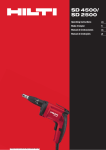
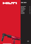
1
DX 351 BT/BTG Operating instructions en Mode d’emploi fr zh ja ko ar Printed: 26.09.2014 | Doc-Nr: PUB / 5069827 / 000 / 03 1 쐃 쐇 쐋 쐏 DX 351 BTG 쐊 쐄 쐎 쐂 쐆 쐅 쐉 DX 351 BT 쐈 2 씈 씉 씊 씋 씌 1 3 2 DX 씍 Printed: 26.09.2014 | Doc-Nr: PUB / 5069827 / 000 / 03 씎 씏 351 3 4 7.2 mm TX-BT 4/7 5 6 NO water oil etc. NO debris Trec >6 > 15 [0.236"] [0.591"] > 15 [0.591"] 10 ≥ 8 mm [5/16″] >6 [0.236"] ≥ 6 mm [0.236"] 8 ≥ 12 mm [0.472"] 7 9 Sichtbarer Ring Visible ring Cercle visible Aro visible 12 8mm [5/16"] HG L 11 13 Printed: 26.09.2014 | Doc-Nr: PUB / 5069827 / 000 / 03 14 15 16 17 18 19 360 20 21 22 23 24 25 Printed: 26.09.2014 | Doc-Nr: PUB / 5069827 / 000 / 03 26 27 28 29 30 31 32 33 34 Printed: 26.09.2014 | Doc-Nr: PUB / 5069827 / 000 / 03 ORIGINAL OPERATING INSTRUCTIONS DX 351 BT/BTG powder-actuated tool It is essential that the operating instructions are read before the tool is operated for the first time. Always keep these operating instructions together with the tool. Ensure that the operating instructions are with the tool when it is given to other persons. Description of main parts 쐃 Fastener guide 쐇 Threaded sleeve 쐋 Piston return spring 쐏 Cartridge strip ejector 쐄 Ventilation slots 쐂 Power regulation indicator 쐆 Power regulation wheel 쐊 Housing, black 쐎 Trigger 쐅 Grip 쐈 Cartridge guideway 쐉 Grip pad Printed: 26.09.2014 | Doc-Nr: PUB / 5069827 / 000 / 03 1.1 Basic safety instructions In addition to the safety precautions listed in the individual sections of these operating instructions, the following points must be strictly observed at all times. 1.2 Only use Hilti cartridges or cartridges of equivalent quality The use of cartridges of inferior quality in Hilti tools may lead to build-up of unburned powder, which may explode and cause severe injuries to operators and bystanders. At a minimum, cartridges must either: a) Be confirmed by their supplier to have been successfully tested in accordance with EU standard EN 16264 NOTE: ● All Hilti cartridges for powder-actuated tools have been tested successfully in accordance with EN 16264. ● The tests defined in the EN 16264 standard are system tests carried out by the certification authority using specific combinations of cartridges and tools. The tool designation, the name of the certification authority and the system test number are printed on the cartridge packaging. Tool components 씈 Fastener guide* 씉 Piston brake 씊 Piston* 씋 Piston return spring 씌 Piston guide 씍 Casing, black 씎 Piston stop, right 씏 Piston stop, left * These parts may be replaced by the user. Contents 1. Safety precautions 2. General information 3. Technical description 4. Insert tools and accessories 5. Technical data 6. Before use 7. Operation 8. Care and maintenance 9. Troubleshooting 10. Disposal 11. Manufacturer's warranty – DX tools 12. EC declaration of conformity (original) 13. CIP approval mark 14. Health and safety of the user 1. Safety precautions or b) Carry the CE conformity mark (mandatory in the EU as of July 2013). See packaging sample at: www.hilti.com/dx-cartridges Page 1 3 3 4 6 6 6 8 10 13 13 13 14 14 1.3 Use as intended The DX 351 BT and DX 351 BTG are designed for professional use in fastening applications in construction where X-BT threaded studs are driven into steel. 1.4 Improper use ● Operate the tool only in well-ventilated working areas. ● Manipulation or modification of the tool is not permissible. ● Do not operate the tool in an explosive or flammable atmosphere, unless the tool is specially approved for such use. ● Use only original Hilti fasteners, cartridges, accessories and spare parts or those of equivalent quality. ● Observe the information printed in the operating instructions concerning operation, care and maintenance. 1 en en ● Never point the tool at yourself or any bystander. ● Never press the muzzle of the tool against your hand or other part of your body. ● Do not drive nails into excessively hard or brittle materials such as glass, marble, plastic, bronze, brass, copper, natural rock, insulation material, hollow brick, glazed tile, thin-gauge sheet metal (< 4 mm), grey cast iron, spheroidal cast iron and gas concrete. 1.5 Technology ● This tool is designed with the latest available technology. ● The tool and its ancillary equipment may present hazards when used incorrectly by untrained personnel or not as directed. 1.6 Making the workplace safe ● Ensure that the workplace is well lit. ● Objects which could cause injury should be removed from the working area. ● Operate the tool only in well-ventilated working areas. ● The tool is for hand-held use only. ● Avoid unfavorable body positions. Work from a secure stance and stay in balance at all times ● Keep other persons, children in particular, outside the working area. ● Before using the tool, make sure that no one is standing behind or below the point where fasteners are to be driven. ● Keep the grip dry, clean and free from oil and grease. 1.7 General safety precautions ● Operate the tool only as directed and only when it is in faultless condition. ● If a cartridge misfires or fails to ignite, proceed as follows: 1. Keep the tool pressed against the working surface for 30 seconds. 2. If the cartridge still fails to fire, withdraw the tool from the working surface, taking care that it is not pointed towards your body or bystanders. 3. Manually advance the cartridge strip one cartridge. Use up the remaining cartridges on the strip. Remove the used cartridge strip and dispose of it in such a way that it can be neither reused nor misused. ● Never attempt to pry a cartridge from the magazine strip or the tool. ● Keep the arms flexed when the tool is fired (do not straighten the arms). ● Never leave the loaded tool unattended. ● Always unload the tool before beginning cleaning, servicing or changing parts and before storage. 2 Printed: 26.09.2014 | Doc-Nr: PUB / 5069827 / 000 / 03 ● Unused cartridges and tools not presently in use must be stored in a place where they are not exposed to humidity or excessive heat. The tool should be transported and stored in a toolbox that can be locked or secured to prevent use by unauthorized persons. 1.8 Temperature ● Do not disassemble the tool while it is hot. ● Never exceed the recommended maximum fastener driving rate (number of fastenings per hour). The tool may otherwise overheat. ● Should the plastic cartridge strip begin to melt, stop using the tool immediately and allow it to cool down. 1.9 Requirements to be met by users ● The tool is intended for professional use. ● The tool may be operated, serviced and repaired only by authorised, trained personnel. This personnel must be informed of any special hazards that may be encountered. ● Proceed carefully and do not use the tool if your full attention is not on the job. ● Stop working with the tool if you feel any pain or discomfort. 1.10 Personal protective equipment ● The operator and other persons in the immediate vicinity must always wear approved eye protection, a hard hat and suitable ear protection. 2. General information 2.1 Signal words -WARNINGThe word WARNING is used to draw attention to a potentially dangerous situation which could lead to severe personal injury or death. -CAUTIONThe word CAUTION is used to draw attention to a potentially dangerous situation which could lead to minor personal injury or damage to the equipment or other property. -NOTEUsed to draw attention to an instruction or other useful information. 2.2 Pictograms Warning signs The numbers refer to the illustrations. The illustrations can be found on the fold-out cover pages. Keep these pages open while you read the operating instructions. In these operating instructions, the designation “the tool” always refers to the DX 351 BT/BTG powder-actuated tool. Location of identification data on the tool The type designation and the serial number are printed on the type plate on the tool. Make a note of this information in your operating instructions and always refer to it when making an enquiry to your Hilti representative or service department. Type: DX 351 BT/BTG Symbols Serial no.: General warning Warning: hot surface Read the operation instructions before use Return waste material for recycling Obligation signs Wear eye protection Wear a safety helmet Wear ear protection 3. Technical description The Hilti DX 351BT and DX 351BTG are powder-actuated fastening tools for driving X-BT threaded studs into steel. The tool works on the well-proven piston principle and is therefore not related to high-velocity tools. The piston principle provides an optimum of working and fastening safety. The tool works with cartridges of 6.8/11 caliber. Piston return and cartridge transport is fully automatic. This permits fastenings to be made very quickly and economically with nails and threaded studs. As with all powder-actuated tools, the tool, magazine, fastener program and cartridge program form a “technical unit”. This means that optimal fastening with this system can only be achieved if the fasteners and cartridges are specially manufactured for it, or products of equivalent quality, are used. The fastening and application recommendations given by Hilti are only applicable if these conditions are observed. The tool features 5-way safety – for the safety of the operator and bystanders. The piston principle 1 The energy from the propellant charge is transferred to a piston, the accelerated mass of which drives the fastener into the base material. As approximately 95 % of the kinetic energy is absorbed by the piston, the fastener is driven into the base material at much reduced velocity (less than 100 m/sec.) in a controlled manner. The driving process ends when the piston reaches the end of its travel. This makes dangerous through-shots virtually impossible when the tool is used correctly. 3 Printed: 26.09.2014 | Doc-Nr: PUB / 5069827 / 000 / 03 en The drop-firing safety device 2 is the result of coupling the firing mechanism with the cocking movement. This is designed to help prevent the Hilti DX tool from firing when it is dropped onto a hard surface, no matter at which angle the impact occurs. 2 4 3 5 en The trigger safety device 3 ensures that the cartridge cannot be fired simply by pulling the trigger only. The tool can be fired only when fully depressed. The contact pressure safety device 4 requires the tool to be fully depressed with a significant force. The tool can be fired only when pressed fully in this way. In addition, all Hilti DX tools are equipped with an unintentional firing safety device 5 . This prevents the tool from firing if the trigger is pulled and the tool then pressed against the work surface. The tool can be fired only when it is first pressed 쩸 correctly and 쩹 the trigger then pulled. 2 1 4. Insert tools and accessories Cartridges Ordering designation Item no. Quantity Color Power 6.8/11 M brown, “High-precision“ 377204/3 100 Brown Extra light These cartridges have been designed specially for the X-BT system. Their special power level ensures that driving power remains within a very narrow scatter band. Fasteners Stainless steel threaded studs Ordering designation Item no. Quantity X-BT W10-24-6 SN12-R X-BT M10-24-6 SN12-R X-BT M8-15-6 SN12-R X-BT W10-26-6-R X-BT M10-24-6-R X-BT M8-15-6-R Grating flanges 377076/5 377078/1 377074/0 377075/7 377077/3 377073/2 100 100 100 100 100 100 Ordering designation Item no. Quantity X-FCM-R 25/30 X-FCM-R 11/4-1/2 X-FCM-R 35/40 X-FCM-R 45/50 247181/1 247173/8 247171/2 247172/0 100 100 100 100 Ordering designation Item no. Quantity X-351-BT FG W1024 X-351-BT FG M1024 X-351-BT FG G 378673/8 378674/6 378675/3 1 1 1 Ordering designation Item no. Quantity X-351-BT P 1024 X-351-BT P G 378676/1 378677/9 1 1 Fastener guide Piston 4 Printed: 26.09.2014 | Doc-Nr: PUB / 5069827 / 000 / 03 Prevention of misuse: – When the piston tip is worn or damaged, never try to grind the tip in order to re-use the piston. This may cause serious damage to the tool and will adversely affect fastening quality. – Please refer to the table below for the right fastener guide/piston/fastener combination. Use of the wrong combination may result in damage to the tool. en Zuitable fastener guide / piston / fastener / combinations Fastener guide Piston type Fastener X-351-BT FG W1024 X-351-BT P 1024 X-BT W10-24-6 SN12-R X-BT W10-24-6-R X-351-BT FG M1024 X-351-BT P 1024 X-BT M10-24-6 SN12-R X-BT M10-24-6-R X-351-BT FG G X-351-BT P G X-BT M8-15-6 SN12-R X-BT M8-15-6-R Accessories Ordering designation Item no. Application X-351-BT CP coating protector 331343/9 X-BT PRG 8/15 power regulation guide X-BT PRG 10/24 power regulation guide 377088/0 Attachment for the fastener guide designed to prevent damage to painted surfaces. For checking that fasteners (studs) are driven to the correct depth for X-BT M8 studs. For checking that fasteners (studs) are driven to the correct depth for X-BT M10, X-BT W10 threaded studs. For drilling holes for the X-BT M10, X-BT W10 or X-BT M8 threaded studs. Ideal for use in narrow openings where access is restricted. For drilling holes for the X-BT M10, X-BT W10 or X-BT M8 threaded studs. Ideal for grating fastenings. For drilling holes for the X-BT M10, X-BT W10 or X-BT M8 threaded studs. Ideal for grating fastenings where the parts to be fastened are of greater height. For drilling holes with the TX-BT4/7-... stepped drill bits Positioning aid for drilling holes, particularly where access is restricted. 377089/8 TX-BT 4/7-80 stepped drill bit 377079/9 TX-BT 4/7-110 stepped drill bit 377080/7 TX-BT 4/7-150 stepped drill bit 377081/5 XBT4000-A drill X-BT CD 18/24 centering device 378885/8 Qty. 10 1 1 10 10 10 1 5 Printed: 26.09.2014 | Doc-Nr: PUB / 5069827 / 000 / 03 Cleaning set Hilti spray, flat brush, round brush 19/31 mm, round brush 4.5 mm, round brush 9 mm, cleaning cloth, scraper en 5. Technical data Tool Weight Length of tool Cartridges Recommended max. fastener driving frequency: Cocking movement Cocking pressure DX 351 BT 2.28 kg (5 Ibs) 403 mm (15.9″) 6.8/11 M (27 cal. short) brown 700/h 59 mm (2.3″) 100 N DX 351 BTG 2.36 kg (5.2 Ibs) 431 mm (16.9″) 6.8/11 M (27 cal. short) brown 700/h 59 mm (2.3″) 100 N Right of technical modification reserved 6. Before use Check all external parts of the tool for damage at regular intervals and check that all controls operate properly. Do not operate the tool when parts are damaged or when the controls do not operate properly. If necessary, have the tool repaired at a Hilti service centre. ● Check the piston for wear (see “8.4 Care and maintenance”). ● 6.1 Tool inspection Ensure that there is no cartridge strip in the tool. If there is a cartridge strip in the tool, remove it by hand from the tool. ● 7. Operation -WARNING● -WARNING● ● ● The base material may splinter when a fastener is driven or fragments of the cartridge strip may fly off. Flying fragments may injure parts of the body or the eyes. Wear safety glasses and a hard hat (users and bystanders). ● ● Under certain circumstances, the tool can be made ready to fire by pressing it against a part of the body (e. g. a hand). When in the “ready to fire” state, a fastener or piston could be driven into a part of the body. Never press the nosepiece of the tool against parts of the body. -WARNING-CAUTION● ● ● The nail or stud is driven by a cartridge being fired. Excessive noise may damage the hearing. Wear ear protection (users and bystanders). 6 Printed: 26.09.2014 | Doc-Nr: PUB / 5069827 / 000 / 03 ● ● ● Under certain circumstances, the tool can be made ready to fire by pulling back the fastener guide by hand. When in the “ready to fire” state, a fastener or piston could be driven into a part of the body. Never pull back the fastener guide by hand. 7.1 Fastening guidelines -NOTEThese application recommendations must always be observed. For more specific information, refer to the Hilti Fastening Technology Manual, which is available from your local Hilti organisation. 7.1.1 Driving threaded studs 1. Mark the point where the stud is to be driven. 2. Drill a hole. Continue drilling until the drill bit cuts a bright ring around the hole. 3. Keep the hole clean (clean away any debris, dirt, water or other liquids). 4. Position the threaded stud in the drilled hole and then press the tool against the working surface at right angles. 5. Pull the trigger. -NOTENever regrind a stepped drill bit. System functionality can otherwise no longer be acheived. 7.2 Technical guidelines 7.2.1 Recommended torque Trec ≤ 8 Nm (5.9 ft-Ib) Hilti screwdriver Torque setting SF 121-A SF 150-A SF 180-A 11 9 8 7.2.2 Flange thickness Minimum flange thickness where the stud is driven into the edge of the flange: ≥ 12 mm (0.48 in). 7.2.3 Stud spacing Between threaded studs ≥ 15 mm (0.59 in) Between the threaded stud and the edge of the base material. ≥ 6 mm (0.24 in) 7.5 Loading the powder-actuated tool 1. Push the threaded stud into the tool threaded end first, as far as it will go, until it is held in place in the tool. 2. Push the cartridge strip, narrow end first, into the guideway in the grip of the tool from below, until the full length of the cartridge strip is within the grip. When loading a partly-used cartridge strip, pull the cartridge strip up out of the tool from above by hand until an unused cartridge is in place in the cartridge chamber. 7.6 Setting the fastener driving power 1. Use the power regulation guide to determine the correct driving power setting (the power regulation guide is enclosed in the package with the threaded studs). Perform a test fastening to verify the guideline power setting is correct. 2. If the threaded stud is not driven in to the correct position, adjust the driving power to an appropriate setting by turning the power regulation wheel. 7.7 Driving a threaded stud 1. Position the threaded stud in the predrilled hole and then press the tool against the working surface at right angles. 2. Pull the trigger to drive the stud. -WARNINGDo not attempt to redrive the same threaded stud by firing the tool a second time. Do not drive studs into damaged or previously used holes. 7.8 Unloading the powder-actuated tool 1. Check to ensure that no cartridge strip is in the tool. If there is a cartridge strip in the tool, remove it by pulling it upwards out of the tool from above. 7.3 Power settings Set the driving power on the tool to a value that drives the threaded stud to the correct depth and ensures that a good seal is achieved by the sealing washer. Start with the lowest driving power setting and increase as necessary. 7.4 Fastening gratings X-FCM-R grating flanges Designation Length in mm (in) Fastenable thickness in mm (in) X-FCM-R 25/30 23 mm (0.91″) 30 mm (1.18″) 33 mm (1.30″) 43 mm (1.69″) 25–32 mm (0.98–1.26″) 32–39 mm (1.26–1.54″) 35–42 mm (1.38–1.65″) 45–52 mm (1.77–2.05″) X-FCM-R 11/4-11/2 X-FCM-R 35/40 X-FCM-R 45/50 7 Printed: 26.09.2014 | Doc-Nr: PUB / 5069827 / 000 / 03 en 8. Care and maintenance en When this type of tool is used under normal operating conditions, dirt and residues build up inside the tool and functionally relevant parts are also subject to wear. Regular inspections and maintenance are thus essential in order to achieve reliable operation. We recommend that the tool is cleaned and the piston and piston brake are checked at least weekly when the tool is subjected to intensive use, and at the latest after driving 2,000 fasteners. 8.1 Care of the tool Clean the tool: ● After driving 2,000 studs ● If cartridges misfire ● If driving power is not constant ● If moving parts do not operate freely The outer casing of the tool is manufactured from impact-resistant plastic. The grip comprises a synthetic rubber section. The ventilation slots must be unobstructed and kept clean at all times. Do not permit foreign objects to enter the interior of the tool. Use a slightly damp cloth to clean the outside of the tool at regular intervals. Do not use a spray or steam-cleaning system for cleaning. 8.2 Maintenance Check all external parts of the tool for damage at regular intervals and check that all controls operate properly. Do not operate the tool when parts are damaged or when the controls do not operate properly. If necessary, have the tool repaired at a Hilti service centre. -CAUTION- when cleaning: ● Never use grease for the maintenance/lubrication of parts of the tool. This may lead to malfunctions. Use only Hilti lubricant spray or a product of comparable quality. ● The residues deposited inside DX tools contain substances that may be injurious to your health: – Do not inhale any dust or dirt while cleaning. – Keep the dust or dirt away from foodstuffs. – Wash your hands after cleaning the tool. -CAUTION● ● ● The tool can get hot while operating. You could burn your hands. Do not disassemble the tool while it is hot. Let the tool cool down. 8.3 Disassembling the tool 1. Check to ensure that no cartridge strip is in the tool. If there is a cartridge strip in the tool, remove it by pulling it upwards out of the tool from above. 2. Unscrew and remove the fastener guide. 8 Printed: 26.09.2014 | Doc-Nr: PUB / 5069827 / 000 / 03 3. Rotate the black housing counterclockwise through one complete revolution (360°). This releases the piston stop. 4. Remove the piston from the tool. -NOTEIf the piston is jammed in the piston guide, the complete piston guide must be removed from the tool. 5. Unscrew and remove the black housing completely by turning it counterclockwise. 6. Press the piston guide against the tool with the palm of the hand. 7. Pull the complete unit away from the tool. 8. Pull the black housing away from the piston guide. 9. Ziehen Sie den Kolben aus der Kolbenführung. 8.4 Checking the piston for wear The piston must be replaced if it is: – badly worn – broken – bent (check by rolling it on a flat surface). -WARNINGShould the tip of the piston become worn or damaged, do not attempt to grind it off in order to permit further use. This may negatively affect the quality of the fastening obtained and may result in serious damage to the tool. 8.5 Cleaning the piston 1. Clean the piston with a flat brush. 2. Spray the piston lightly with Hilti spray. 8.6 Cleaning the fastener guide 1. Clean the fastener guide with a small round brush. 2. Spray the fastener guide lightly with Hilti spray. 8.7 Cleaning the cartridge strip guideway 1. Clean the right and the left cartridge strip guideway with the scraper supplied. 8.8 Cleaning the piston guide 1. Clean the inside of the piston guide with a round brush and the outside with a flat brush. 2. Clean the cartridge chamber and the power regulation bore in the end of the piston guide. 3. Spray the inside and the outside of the piston guide lightly with Hilti spray. 8.9 Cleaning inside the housing 1. Clean the inside of the housing with the flat brush. 2. Spray the housing lightly with Hilti spray. 8.10 Assembling the tool 1. Fit the black housing onto the piston guide. 2. Pull the black housing upwards against the spring pressure and hold it securely in this position in your hand. 3. Fit the complete unit into the tool so that the marks on the piston guide and on the metal housing are in alignment. 4. Press in the piston stops when the piston guide has been inserted far enough for the stops to fit into the openings at the side of the piston guide. 5. Release the black housing and screw it on to the tool (only 1–2 turns). 6. Push in the piston as far as it will go. The piston can be inserted only before the black housing is screwed on fully (before the final turn). Then screw on the black housing as far as it will go (until it engages). 7. Press the fastener guide firmly against the piston guide and then screw it on until it engages. en 8.11 Checking the tool following care and maintenance After carrying out care and maintenance on the tool, check that all protective and safety devices are fitted and that they function correctly. -CAUTIONThe use of lubricants other than Hilti spray could damage rubber parts, especially the buffer. 9 Printed: 26.09.2014 | Doc-Nr: PUB / 5069827 / 000 / 03 9. Troubleshooting en Fault Possible cause Remedy Cartridge not transported ■ Damaged cartridge strip ■ Carbon build-up ■ Cartridge strip cannot be removed ■ Tool damaged If the problem persists: ■ Contact Hilti Repair Centre ■ Tool overheated because of high ■ Let the tool cool down and then setting rate ■ Tool damaged -WARNINGNever attempt to pry a cartridge from the magazine strip or tool. Cartridge doesn’t fire Clean the cartridge strip guideway (see 24) carefully try to remove the cartridge strip (If the problem persists: Contact Hilti Repair Center) ■ Contact Hilti Repair Center ■ Bad cartridge ■ Manually advance the cartridge ■ Carbon build-up ■ If the problem occurs more often: strip one cartridge -WARNINGNever attempt to pry a cartridge from the magazine strip or tool. Cartridge strip melts ■ Tool is compressed too long while fastening. ■ Fastening frequency is too high Clean the tool (If the problem persists: Contact Hilti Repair Center) ■ Compress the tool only briefly while fastening. ■ Remove the cartridge strip ■ Disassemble the tool for fast cooling and to avoid possible damage (If the tool cannot be disassembled: Contact Hilti Repair Center) Cartridge falls out of the cartridge strip ■ Fastening frequency is too high ■ Immediately discontinue using -WARNINGNever attempt to pry a cartridge from the magazine strip or tool. ■ Remove cartridge strip ■ Let the tool cool down ■ Clean the tool and remove loose the tool cartridge. (If it is impossible to disassemble the tool: Contact Hilti Repair Center) 10 Printed: 26.09.2014 | Doc-Nr: PUB / 5069827 / 000 / 03 Fault Possible cause Remedy The operator notices: ■ increased contact pressure ■ increased trigger force ■ power regulation stiff to adjust ■ cartridge strip is difficult to remove ■ Carbon build-up ■ Clean the tool ■ Check that the correct cartridges Threaded studs driven to different depths or sealing washer pressure/contact not constant ■ Hole not deep enough ■ Drill to correct depth ■ Piston broken or damaged ■ Fastener guide damaged ■ Damaged protective cover ■ Tool misfires ■ Replace the piston. ■ Replace the fastener guide. ■ Replace the protective cover. ■ Change the cartridge strip (take a are used (see 1.2) and that they are in faultless condition. ■ Carbon build-up strip from a new, dry package if necessary). Clean the cartridge strip guideway and cartridge chamber. ■ Check driving power using the power regulation guide. ■ Clean the tool. ■ Stud driven too deeply ■ Reduce driving power (power ■ Dirt or foreign matter in the hole ■ Remove liquids, debris, or other ■ Wrong driving power setting Damage to the painted surface on the underside of the base material regulation). ■ Steel base material too thin (< 8 mm) ■ Hole not deep enough Threaded stud doesn’t hold in the base material when torque is applied => visible ring . ■ Dirt or foreign matter in the hole foreign matter from the hole before installing the stud. ■ Drive studs only on steel base material ≥ 8 mm. ■ Drill to correct depth => visible ring . ■ Remove liquids, debris, or other foreign matter from the hole before installing the stud. ■ Drill to correct depth => visible ring . ■ Hole damaged or previously used ■ Drill new hole. ■ Wrong drill bit used ■ Use appropriate drill bit ■ Too much torque applied ■ Use appropriate amount of torque (see 7.2.1 Recommended torque) ■ Hole not deep enough 11 Printed: 26.09.2014 | Doc-Nr: PUB / 5069827 / 000 / 03 en en Fault Possible cause Remedy The thread on the stud is damaged ■ Fastener guide damaged ■ Replace the fastener guide. Stud doesn’t hold in the base material ■ Steel base material too thin ■ Drive studs only on steel base (< 8 mm) ■ Hole damaged or previously used ■ Driving power too low ■ Hole not deep enough ■ Drill new hole. ■ Increase driving power. ■ Drill to correct depth ■ Wrong drill bit used ■ Dirt/debris in hole ■ Use correct drill bit ■ Remove liquids, debris or other material ≥ 8 mm. => visible ring . foreign matter from the hole before installing the stud. Piston jams in the piston guide ■ Damaged piston ■ Remove the cartridge strip ■ Kolbenführung ■ Check the piston and replace it if necessary ■ Clean the tool ■ Carbon build-up Trigger can’t be pulled ■ Tool not pressed fully against the ■ Press the tool fully against the work surface ■ Piston fitted incorrectly ■ Tool defective ■ Fit the piston correctly. ■ Contact your Hilti Center. 12 Printed: 26.09.2014 | Doc-Nr: PUB / 5069827 / 000 / 03 work surface. 10. Disposal Most of the materials from which Hilti power actuated tools are manufactured can be recycled. The materials must be correctly separated before they can be recycled. In many countries, Hilti has already made arrangements for taking back your old powder actuated tools for recycling. Please ask your Hilti customer service department or Hilti sales representative for further information. Should you wish to return the power actuated tool yourself to a disposal facility for recycling, proceed as follows: Dismantle the tools as far as possible without the need for special tools. 11. Manufacturer's warranty – DX Tools Hilti warrants that the tool supplied is free of defects in material and workmanship. This warranty is valid so long as the tool is operated and handled correctly, cleaned and serviced properly and in accordance with the Hilti Operating Instructions, and the technical system is maintained. This means that only original Hilti consumables, components and spare parts, or other products of equivalent quality, may be used in the tool. This warranty provides the free-of-charge repair or replacement of defective parts only over the entire lifespan of the tool. Parts requiring repair or replacement as a result of normal wear and tear are not covered by this warranty. Hilti is not obligated for direct, indirect, incidental or consequential damages, losses or expenses in connection with, or by reason of, the use of, or inability to use the tool for any purpose. Implied warranties of merchantability or fitness for a particular purpose are specifically excluded. For repair or replacement, send tool or related parts immediately upon discovery of the defect to the address of the local Hilti marketing organization provided. This constitutes Hilti's entire obligation with regard to warranty and supersedes all prior or contemporaneous comments and oral or written agreements concerning warranties. Additional claims are excluded, unless stringent national rules prohibit such exclusion. In particular, 12. EC declaration of conformity (original) Designation: Type: Powder-actuated tool DX 351BT/BTG Year of design: 2003 We declare, on our sole responsibility, that this product complies with the following directives and standards: 2006/42/EC, 2011/65/EU. Technical documentation filed at: Hilti Entwicklungsgesellschaft mbH Zulassung Elektrowerkzeuge Hiltistrasse 6 86916 Kaufering Deutschland Hilti Corporation, Feldkircherstrasse 100, FL-9494 Schaan Norbert Wohlwend Tassilo Deinzer Head of Quality & Processes Management Head BU Measuring Systems BU Direct Fastening BU Measuring Systems 08/2012 08/2012 13 Printed: 26.09.2014 | Doc-Nr: PUB / 5069827 / 000 / 03 en 13. Confirmation of CIP testing en The Hilti DX 351 BT and DX 351 BTG have been system and type tested. As a result, the tools bear the squareshaped PTB approval mark showing approval number S 807. In this way, Hilti guarantees compliance with the approved type. Unacceptable/inadmissible defects, deficiencies, etc. that are determined during use of the tool must be reported to the manager responsible at the approval authority (PTB) and to the Office of the Permanent International Commission (C.I.P.). 14. Health and safety of the user Noise information The following table provides noise measurement information: Powder-actuated tool Type: Model: Caliber: Power setting: Application: DX 351-BT / DX 351 BTG Serial production 6.8/11 brown 3 Fastening of X-BT M10-24-6 onto pre-drilled steel platting 8 mm thick Declared measured values of noise characteristics according to 2006/42/EC Machinery Directive in conjunction with E DIN EN 15895 Noise (power) level: LWA, 1s1 109 dB(A) Emission noise-pressure level in the work station: LpA, 1s2 105 dB(A) Peak sound pressure emission level: LpC, peak3 136 dB(C) Operation and set-up conditions: Set-up and operation of the pin driver in accordance with E DIN EN 15895-1 in the semi-anechoic test room of Müller-BBM GmbH. The ambient conditions in the test room conform to DIN EN ISO 3745. Testing procedure: Enveloping surface method in anechoic room on reflective surface area in accordance with E DIN EN 15895, DIN EN ISO 3745 and DIN EN ISO 11201. NOTE: The noise emissions measured and the associated measurement uncertainty represent the upper limit for the noise values to be expected during the measurements. Variations in operating conditions may cause deviations from these emission values. 1 ± 2 dB (A) 2 ± 2 dB (A) 3 ± 2 dB (C) Vibration The declared total vibration value according to 2006/42/EC does not exceed 2.5 m/s2. Further information regarding the health and safety of the user can be found at the Hilti web site: www.hilti.com/hse 14 Printed: 26.09.2014 | Doc-Nr: PUB / 5069827 / 000 / 03 NOTICE ORIGINALE Appareil de scellement DX 351 BT/BTG Avant de mettre en marche l’appareil, lire absolument son mode d’emploi. Le présent mode d’emploi doit toujours accompagner l’appareil. Ne prêter ou céder l’appareil à quelqu’un d’autre qu’en lui fournissant aussi le mode d’emploi. Désignation des pièces principales 쐃 Canon 쐇 Douille filetée 쐋 Boîtier noir 쐏 Ejection des cartouches 쐄 Ouïes d'aération 쐂 Graduation du réglage de la puissance 쐆 Molette de réglage de la puissance 쐊 Boîtier noir 쐎 Détente 쐅 Poignée 쐈 Amenée des cartouches 쐉 Rembourrage de poignée 1.1 Consignes de sécurité générales Outre les consignes techniques de sécurité indiquées dans les différents chapitres du présent mode d’emploi, il a y lieu de toujours respecter strictement les directives suivantes. 1.2 N'utiliser que des cartouches Hilti ou des cartouches de qualité équivalente. L'utilisation de cartouches de qualité moindre dans les outils Hilti risque d'entraîner une accumulation de poudre non consumée susceptible d'exploser subitement et de causer de graves blessures aux opérateurs et aux personnes alentour. Les cartouches doivent satisfaire l'une des exigences minimales suivantes : a) Leur fournisseur doit pouvoir confirmer le résultat positif des essais conformément à la norme européenne EN 16264 Eléments composant l'appareil 씈 Canon* 씉 Frein de piston 씊 Piston* 씋 Boîtier noir 씌 Guide-piston 씍 Boîtier noir 씎 Butée de piston, droite 씏 Butée de piston, gauche * Ces pièces peuvent être remplacées par l'utilisateur. Contenu 1. Consignes de sécurité 2. Consignes générales 3. Description 4. Outils et accessoires 5. Caractéristiques techniques 6. Mise en marche 7. Utilisation 8. Nettoyage et entretien 9. Guide de dépannage 10. Recyclage 11. Garantie constructeur des appareils 12. Déclaration de conformité CE (original) 13. Marquage CIP 14. Santé de l'utilisateur et sécurité 1. Consignes de sécurité Page 15 17 17 18 20 20 20 22 24 27 27 27 28 28 REMARQUE: ● Toutes les cartouches pour appareils de scellement ont été testées avec succès conformément à la norme EN 16264. ● Les contrôles définis par la norme EN 16264 sont des tests des systèmes correspondant à des combinaisons spécifiques de cartouches et outils, qui sont agréés par des organismes de certification. La désignation de l'outil, le nom de l'organisme de certification et le numéro du système sont imprimés sur l'emballage de la cartouche. ou b) Elles doivent porter le marquage CE de conformité (obligatoire dans l'UE à partir de juillet 2013) Voir exemple d'emballage à l'adresse : www.hilti.com/dx-cartridges 1.3 Utilisation conforme à l'usage prévu Le DX 351BT et le DX 351BTG sont destinés aux utilisateurs professionnels dans l'industrie et l'artisanat de la construction pour la fixation de goujons filetés X-BT dans l'acier. 1.4 Utilisation abusive ● Utiliser l'appareil uniquement dans des emplacements bien aérés. ● Toutes manipulations ou modifications sur l’appareil sont interdites. 15 Printed: 26.09.2014 | Doc-Nr: PUB / 5069827 / 000 / 03 fr fr ● L'appareil ne doit pas être utilisé dans une atmosphère déflagrante ou inflammable, sauf s'il est spécifiquement agréé pour cela.. ● Pour éviter tout risque de blessure, utiliser uniquement des éléments de fixation, cartouches, accessoires et pièces de rechange Hilti d’origine ou de qualité équivalente. ● Bien respecter les données concernant le fonctionnement, le nettoyage et l’entretien de l’appareil qui figurent dans le présent mode d’emploi. ● Ne jamais pointer l’appareil contre vous-même ou quelqu’un d’autre. ● Ne jamais appuyer contre la paume de votre main ou contre une autre partie de votre corps. ● Ne jamais implanter de clous dans des supports trop durs ou cassants, tels que le verre, le marbre, le plastique, le bronze, le laiton, le cuivre, la roche, les matériaux isolants, la brique creuse, la brique céramique, les tôles minces (< 4 mm), la fonte et le béton cellulaire. 1.5 État de la technique ● L’appareil DX 460 est conçu et fabriqué d’après l’état le plus récent de la technique. ● L’appareil et ses accessoires peuvent être dangereux s’ils sont utilisés incorrectement par du personnel non formé ou de manière non conforme à l’usage prévu. 1.6 Aménagement correct du poste de travail ● Veiller à bien éclairer l’endroit. ● Utiliser l'appareil uniquement dans des emplacements bien aérés. ● L’appareil doit être utilisé uniquement guidé des deux mains. ● Eviter toute posture anormale du corps. Veiller à toujours rester stable et à garder l'équilibre. ● Lors du travail, tenir toute tierce personne, notamment les enfants, éloignés de l’endroit où vous travaillez. ● Avant d’implanter des clous, toujours vérifier que personne ne se trouve derrière ou dessous l’endroit où vous travaillez. ● Toujours bien nettoyer et sécher la poignée pour enlever toute trace d’huile et de graisse. 1.7 Dangers généraux dus à l’appareil ● Utiliser l’appareil uniquement s’il est dans un état impeccable et seulement conformément à l’usage prévu. ● Lorsque la cartouche ne percute pas, toujours procéder comme suit: 1. Tenir l’appareil appuyé contre la surface de travail pendant 30 secondes. 16 Printed: 26.09.2014 | Doc-Nr: PUB / 5069827 / 000 / 03 2. Si la cartouche ne percute toujours pas, retirer l’appareil de la surface de travail, prendre soin de ne jamais le pointer contre vous ou en direction de votre entourage. 3. Armer l’appareil pour faire avancer la bande-chargeur d’une cartouche; continuer d’utiliser les cartouches qui restent dans la bande-chargeur: une fois la bande-chargeur utilisée, l’enlever de telle sorte qu’elle ne puisse être ni réutilisée, ni utilisée à mauvais escient. ● Ne jamais essayer d’enlever de force des cartouches de leur bande-chargeur ou de l’appareil. ● Lorsque vous utilisez l’appareil, garder les bras fléchis (ne tas tendre les bras). ● Ne jamais laisser un appareil chargé sans surveillance. ● Toujours décharger l’appareil avant de le nettoyer, de l’entretenir, de le réviser et de le stocker. ● Les cartouches non utilisées et les appareils qui ne servent pas doivent être rangés au sec et à l'abri de toute chaleur excessive. L'appareil doit être transporté et stocké dans un coffret, après l'avoir sécurisé contre toute mise en marche intempestive. 1.8 Dangers thermiques ● Ne jamais démonter l’appareil lorsqu’il est très chaud. ● Ne jamais dépasser la cadence de tir recommandée (le nombre de tirs par heure) car l’appareil risquerait de s’échauffer. ● Si le plastique des bandes-chargeurs de cartouches commence à fondre, toujours laisser refroidir l’appareil. 1.9 Exigences concernant les utilisateurs ● L’appareil est destiné aux utilisateurs professionnels. ● L’appareil ne doit être utilisé, nettoyé et révisé que par du personnel agréé, formé spécialement, qui doit être au courant notamment de tous les risques potentiels. ● Restez toujours concentré sur votre travail. Procédez de manière réfléchie et n’utilisez pas l’appareil si vous n’êtes pas complètement concentré sur votre travail. En cas de malaise, arrêtez le travail. ● Aux Pays-Bas, en France et en Belgique, les utilisateurs doivent avoir au moins 18 ans. 1.10 Équipement personnel de protection ● L'utilisateur et les personnes se trouvant à proximité pendant l'utilisation de l'appareil doivent porter des lunettes de protection adaptées, un casque de protection et un casque antibruit approprié. 2. Consignes générales 2.1 Termes signalant un danger -AVERTISSEMENTPour attirer l'attention sur une situation pouvant présenter des dangers susceptibles d'entraîner des blessures corporelles graves ou la mort. -ATTENTIONPour attirer l'attention sur une situation pouvant présenter des dangers susceptibles d'entraîner des blessures corporelles légères ou des dégâts matériels. Les chiffres renvoient aux illustrations correspondant au texte et se trouvant sur les pages rabattables. Pour lire le mode d'emploi, rabattre ces pages de manière à voir les illustrations. Dans le présent mode d'emploi, "l'appareil" désigne toujours l'appareil de scellement DX 351 BT/BTG. -REMARQUEPour des conseils d'utilisation et autres informations utiles. Identification de l'appareil La désignation et le numéro de série du modèle se trouvent sur la plaque signalétique de l'appareil. Inscrire ces renseignements dans le mode d'emploi et toujours s'y référer pour communiquer avec notre représentant ou agence Hilti. 2.2 Pictogrammes Symboles d'avertissement Symboles Type : DX 351 BT/BTG N° de série : Avertissement danger général Avertissement surfaces chaudes Lire le mode d'emploi avant d'utiliser l'appareil Recycler les déchets Symboles d'obligation Porter des lunettes de protection Porter un casque de protection Porter un casque antibruit 3. Description Les appareils Hilti DX 351BT et DX 351BTG sont des appareils de scellement qui permettent de fixer des goujons filetés X-BT dans de l'acier. L’appareil DX 351 offre une quintuple protection pour une parfaite sécurité de l’utilisateur et de son entourage. L’appareil est équipé d’un piston intermédiaire aux qualités éprouvées (il n’est donc pas classé dans la catégorie des appareils grande vitesse, dits «pistolets»!), qui lui confère une sécurité d’emploi optimale et permet des fixations fiables. Comme charges propulsives, on utilise des cartouches de calibre 6,8/11. Le principe du piston DX Hilti Le retour du piston et l'avance des cartouches s'opèrent automatiquement. Il est ainsi possible de poser des clous et des boulons de manière très économique. Comme tous les autres appareils de scellement à cartouches Hilti, le DX 351 n’est qu’un élément du système de fixation complet et homogène Hilti qui comprend, non seulement l’appareil, mais aussi les cartouches et les éléments de fixation. Ceci implique que l’utilisateur ne peut travailler sans problème avec ce système que s’il utilise les éléments de fixation et les cartouches spécialement fabriqués par Hilti pour cet usage ou d’autres produits de qualité équivalente. Les recommandations données par Hilti concernant la mise en place de ses fixations sont valables uniquement dans ces conditions! 1 L’énergie de la charge propulsive est transmise à un piston dont la masse, accélérée, enfonce l’élément de fixation dans le matériau support. Comme le piston absorbe env. 95 % de l’énergie cinétique, l’élément pénètre à vitesse fortement réduite (inférieure à 100 m/s) dans le matériau support. L’élément est implanté lorsque le piston vient terminer sa course en position de butée dans l’appareil, ce qui exclut pratiquement tous transpercements dangereux du matériau support, à condition, bien sûr, que l’appareil soit correctement utilisé. La sécurité contre les tirs intempestifs en cas de chute 2 résulte de l’action combinée du mécanisme de percus17 Printed: 26.09.2014 | Doc-Nr: PUB / 5069827 / 000 / 03 fr sion et du mouvement de va-et-vient. Elle évite toute percussion inopinée si l’appareil DX 351 Hilti vient à tomber sur une surface dure, quel que soit, d’ailleurs, l’angle de chute. fr 2 4 3 5 La sécurité de détente 3 évite toute percussion de la charge propulsive si la détente seule est pressée. Ainsi, l’appareil DX 351 ne peut tirer que s’il est appuyé fermement, en plus, contre le matériau support. La sécurité d’appui 4 nécessite d’exercer une force d’appui supérieure à 50 N pour produire la percussion. Le tir n’est possible que si l’appareil DX 351 est appuyé à fond contre le matériau support. Par ailleurs, l’appareil DX 351 est équipé d’une sécurité de déclenchement 5 qui empêche toute percussion inopinée si la détente est pressée et l’appareil mis ensuite en appui contre la surface de travail. Ainsi, le tir ne peut être déclenché que si l’appareil est d’abord fermement et correctement appuyé contre le matériau support 쩸, puis sa détente pressée alors seulement 쩹. 2 1 4. Outils et accessoires Cartouches Désignation Article n° Pièce Couleur Charge 6.8/11 M marron "High Precision" 377204/3 100 marron ultrafaible Cette cartouche a été fabriquée spécialement pour le système X-BT. Elle possède un niveau d'énergie spécifique et garantit une bonne répartition de l'énergie. Assortiment d'éléments Goujons filetés en acier inox Désignation Article n° Pièce X-BT W10-24-6 SN12-R X-BT M10-24-6 SN12-R X-BT M8-15-6 SN12-R X-BT W10-26-6-R X-BT M10-24-6-R X-BT M8-15-6-R Brides de fixation des grilles 377076/5 377078/1 377074/0 377075/7 377077/3 377073/2 100 100 100 100 100 100 Désignation Article n° Pièce X-FCM-R 25/30 X-FCM-R 11/4-1/2 X-FCM-R 35/40 X-FCM-R 45/50 247181/1 247173/8 247171/2 247172/0 100 100 100 100 Canon Désignation Article n° Pièce X-351-BT FG W1024 X-351-BT FG M1024 X-351-BT FG G 378673/8 378674/6 378675/3 1 1 1 Piston Désignation Article n° Pièce X-351-BT P 1024 X-351-BT P G 378676/1 378677/9 1 1 18 Printed: 26.09.2014 | Doc-Nr: PUB / 5069827 / 000 / 03 Prévention contre toute erreur d’utilisation: – Si la tête du piston est usée ou abîmée, ne jamais essayer de la réaffûter pour réutiliser le piston: dans le cas contraire, vous risqueriez, non seulement d’abîmer sérieusement l’appareil, mais aussi d’obtenir des fixations de bien moins bonne qualité. – Pour choisir l’embase/le piston/l’élément les mieux adaptés entre eux, vous reporter au tableau ci-dessous. Si vous n’utilisez pas la combinaison qui convient le mieux, vous risquez d’abîmer l’appareil.. Classement Canon/Type de piston/Eléments de fixation Canon Type de piston Eléments de fixation X-351-BT FG W1024 X-351-BT P 1024 X-BT W10-24-6 SN12-R X-BT W10-24-6-R X-351-BT FG M1024 X-351-BT P 1024 X-BT M10-24-6 SN12-R X-BT M10-24-6-R X-351-BT FG G X-351-BT P G X-BT M8-15-6 SN12-R X-BT M8-15-6-R fr Accessoires Désignation Article n° Application X-351-BT CP Capot de protection 331343/9 X-BT PRG 8/15 Guide de réglage de puissance 377088/0 X-BT PRG 10/24 Guide de réglage de puissance 377089/8 TX-BT 4/7-80 Foret étagé 377079/9 TX-BT 4/7-110 Foret étagé 377080/7 TX-BT 4/7-150 Foret étagé 377081/5 Capot du canon pour la protection du matériau support verni. Pour le contrôle de la profondeur d'enfoncement correcte du piston pour les goujons filetés X-BT M8 Pour le contrôle de la profondeur d'enfoncement correcte du piston pour les goujons filetés M10, X-BT W10 Pour les perçages destinés à des goujons filetés X-BT M10, X-BT W10 ou X-BT M8. Idéal en cas d'accès difficile Pour les perçages destinés à des goujons filetés X-BT M10, X-BT W10 ou X-BT M8. Idéal pour les fixations de grilles Pour les perçages destinés à des goujons filetés X-BT M10, X-BT W10 ou X-BT M8. Idéal pour les fixations de grilles avec une grande hauteur de fixation. Pour effectuer des forages avec le foret étagé TX-BT4/7-... Support de positionnement pour effectuer des forages (notamment en cas d'accès difficile) XBT4000-A Perceuse X-BT CD 18/24 Support de centrage 378885/8 Pièce 10 1 1 10 10 10 1 19 Printed: 26.09.2014 | Doc-Nr: PUB / 5069827 / 000 / 03 Kit de nettoyage Lubrifiant Hilti en spray, Brosse plate, Ecouvillon 19/31 mm, Ecouvillon 4,5 mm, Ecouvillon 9 mm, Chamoisette, Grattoir 5. Caractéristiques techniques fr Appareil Poids Longueur de l'appareil Cartouches Cadence de tir maximale recommandée: Course d'implantation Force d'appui DX 351 BT 2,28 kg (5 Ibs) 403 mm (15.9″) 6.8/11 M (27 cal. court) marron 700/h 59 mm (2.3″) 100 N DX 351 BTG 2,36 kg (5.2 Ibs) 431 mm (16.9″) 6.8/11 M (27 cal. court) marron 700/h 59 mm (2.3″) 100 N Sous réserve de modifications techniques 6. Mise en marche Vérifier toutes les pièces extérieures de l'appareil pour voir si elles ne sont pas abîmées et s'assurer que tous les organes de commande fonctionnent correctement. Ne pas utiliser l'appareil si des pièces sont abîmées ou si des organes de commande ne fonctionnent pas parfaitement. Faire réparer l'appareil par le S.A.V. Hilti. ● Vérifier l'usure du piston (voir 8.4 Nettoyage et entretien). ● 6.1 Vérification de l'appareil Vérifier qu'aucune bande-chargeur de cartouches ne se trouve dans l'appareil. S'il y en a une, la tirer à la main vers le haut pour la sortir de l'appareil. ● 7. Utilisation -AVERTISSEMENT● -AVERTISSEMENT● ● ● Pendant le tir, la matière peut s'écailler ou des pièces du chargeur de cartouches peuvent être projetées. Les éclats de matière peuvent entraîner des blessures corporelles et aux yeux. Porter (utilisateur et personnes environnantes) des lunettes et un casque de protection. ● ● -AVERTISSEMENT● -ATTENTION● ● ● Le tir de goujons filetés est déclenché par la percussion d'une cartouche. Un bruit trop intense peut entraîner des lésions auditives. Porter (utilisateur et personnes environnantes) un casque antibruit. 20 Printed: 26.09.2014 | Doc-Nr: PUB / 5069827 / 000 / 03 L'appareil peut se déclencher en l'appuyant sur une partie du corps (par ex. la main). La mise sous tension peut aussi entraîner un tir de l'élément de fixation ou du piston dans des parties du corps. Ne jamais appuyer l'appareil contre des parties du corps. ● ● L'appareil peut se déclencher lors du retrait du canon à la main. La mise sous tension peut aussi entraîner un tir de l'élément de fixation ou du piston dans des parties du corps. Ne jamais retirer le canon à la main. 7.1 Directives concernant les fixations -REMARQUEToujours respecter ces directives d'utilisation. Pour plus de détails, demandez à votre Organisation de Vente Hilti le "Manuel des Techniques de Fixation". 7.1.1 Implantation de goujons filetés 1. Repérer le point de fixation. 2. Percer un trou, jusqu'à ce que le foret découpe une forme ronde dans le matériau support. 3. Maintenir le trou à l'abri des copeaux, de la saleté, de l'eau et d'autres liquides. 4. Positionner le goujon fileté directement dans le trou et appuyer l'appareil bien perpendiculairement à la surface de travail. 5. Déclencher le tir. -REMARQUENe jamais réaffûter un foret étagé. Sinon, le système ne peut plus fonctionner. 7.2 Indications techniques 7.2.1 Couple recommandé Trec ″ 8 nm (5.9 ft-ib) Tournevis Hilti Réglage du couple SF 121-A SF 150-A SF 180-A 11 9 8 7.2.2 Epaisseur de bride Epaisseur de bride minimale pour les fixations dans la bride ≥ 12 mm (0.48 in) 7.2.3 Distances de fixation Entre deux goujons filetés ≥ 15 mm (0.59 in) Distance aux bords ≥ 6 mm (0.24 in) 7.3 Réglage de puissance Régler le paramètre d'énergie sur l'appareil, de manière à ce que l'étanchéité de la rondelle-joint soit garantie et que le goujon fileté atteigne une profondeur d'implantation correcte. Commencer à des niveaux de puissance plus faibles et augmenter la puissance si nécessaire. 7.5 Chargement de l'appareil de scellement 1. Enfoncer le goujon fileté (avec la partie filetée d'abord) par devant jusqu'en butée, afin qu'il soit bien maintenu à l'intérieur de l'appareil. 2. Introduire la bande-chargeur de cartouches par son extrémité droite dans le bas de la poignée et la faire avancer jusqu'à ce qu'elle soit complètement enfoncée dans la poignée. Si l'utilisateur souhaite utiliser une bande-chargeur de cartouches déjà entamée, la tirer à la main au-dessus de l'appareil jusqu'à ce qu'une cartouche non utilisée se trouve dans la chambre de combustion. 7.6 Réglage de la puissance 1. Pour obtenir la bonne puissance, utiliser le guide de réglage de puissance (joint à l'emballage des goujons filetés). Procéder à une fixation d'essai afin de vérifier que le réglage de la puissance est approprié. 2. Si le goujon fileté n'est pas posé en bonne position, adapter la puissance de l'appareil en tournant la molette de réglage en conséquence. 7.7 Tir des goujons filetés 1. Positionner le goujon fileté directement dans le trou et appuyer l'appareil bien perpendiculairement à la surface de travail. 2. Appuyer sur la détente pour déclencher le tir. -AVERTISSEMENTNe pas essayer de retirer le même goujon fileté. Ne jamais tirer de goujon fileté dans des trous endommagés ou déjà utilisés. 7.8 Déchargement de l'appareil de scellement 1. Vérifier qu'aucune bande-chargeur de cartouches ne se trouve dans l'appareil. S'il y en a une, la tirer à la main vers le haut pour la sortir de l'appareil. 7.4 Fixations de grilles X-FCM-R Brides de fixation Désignation Longueur mm (inch) Hauteur de fixation mm (inch) X-FCM-R 25/30 23 mm (0.91″) 30 mm (1.18″) 33 mm (1.30″) 43 mm (1.69″) 25–32 mm (0.98–1.26″) 32–39 mm (1.26–1.54″) 35–42 mm (1.38–1.65″) 45–52 mm (1.77–2.05″) X-FCM-R 11/4-11/2 X-FCM-R 35/40 X-FCM-R 45/50 21 Printed: 26.09.2014 | Doc-Nr: PUB / 5069827 / 000 / 03 fr 8. Nettoyage et entretien fr Lors d'un fonctionnement normal et régulier de l'appareil, les pièces constitutives importantes s'encrassent et s'usent. Pour que l'appareil fonctionne de manière fiable et sûre, l'inspecter et l'entretenir régulièrement. Nous recommandons de nettoyer l'appareil et de vérifier les pistons et l'amortisseur au moins une fois par semaine en cas d'utilisation intensive, au plus tard tous les 2.000 tirs! 8.3 Démontage de l'appareil 1. Vérifier qu'aucune bande-chargeur de cartouches ne se trouve dans l'appareil. S'il y en a une, la tirer à la main vers le haut pour la sortir de l'appareil. 2. Dévisser le canon. 3. Tourner le boîtier noir d'un tour complet (360°) vers la droite. La butée de piston est ainsi libérée. 4. Retirer le piston de l'appareil. 8.1 Nettoyage de l'appareil Procéder au nettoyage de l'appareil : ● Après 2'000 tirs ● En cas de ratés (percussion de cartouches) ● En cas de variation de la puissance ● En cas de diminution du niveau de confort de l'appareil La coque extérieure du boîtier de l’appareil est en plastique incassable, la partie préhensible en élastomère. Ne jamais faire fonctionner l’appareil si ses ouïes d’aération sont bouchées ! Eviter toute pénétration de résidus à l’intérieur de l’appareil. Nettoyer régulièrement l’extérieur de l’appareil avec une chamoisette légèrement humidifiée. Pour nettoyer l’appareil, n’utiliser ni appareil diffuseur, ni appareil à jet de vapeur! -REMARQUESi le piston est fixé dans le guide-piston, l'ensemble du guide-piston doit être démonté. 5. Dévisser complètement le boîtier noir vers la gauche. 6. Pousser le guide-piston avec la main contre l'appareil. 7. Retirer l'unité complète de l'appareil. 8. Tirer le boîtier noir du guide-piston. 9. Retirer le piston du guide-piston. 8.2 Entretien Vérifier régulièrement toutes les pièces extérieures de l'appareil pour voir si elles ne sont pas abîmées et s'assurer que tous les organes de commande fonctionnent correctement. Ne pas utiliser l'appareil si des pièces sont abîmées ou si des organes de commande ne fonctionnent pas parfaitement. Faire réparer l'appareil par le S.A.V. Hilti. -ATTENTION- lors du nettoyage : ● Ne jamais utiliser de graisse pour l'entretien / la lubrification des composants de l'appareil. Ceci peut entraîner des dysfonctionnements de l'appareil. Utiliser exclusivement le lubrifiant Hilti ou des produits de qualité équivalente. ● Les dépôts de salissures dans les appareils DX contiennent des substances pouvant nuire à votre santé : – Ne pas respirer les poussières / les salissures issues du nettoyage. – Eviter que la poussière / salissure n'entre en contact avec de la nourriture. – Se laver les mains après le nettoyage de l'appareil. -ATTENTION● ● ● Après utilisation, l'appareil peut être très chaud. L'utilisateur peut se brûler les mains. Ne jamais démonter l'appareil lorsqu'il est très chaud. Le laisser refroidir. 22 Printed: 26.09.2014 | Doc-Nr: PUB / 5069827 / 000 / 03 8.4 Contrôler l'usure du piston Le piston doit être remplacé si – il est trop usé – il est cassé – il est déformé (le contrôler en le roulant sur une surface plane). -AVERTISSEMENTSi la pointe du piston est détériorée ou endommagée, ne pas affûter la pointe pour pouvoir utiliser à nouveau le piston. La qualité de fixation en serait affectée et l'appareil pourrait également subir de sérieux dommages. 8.5 Nettoyage du piston 1. Nettoyer le piston à l'aide d'une brosse plate. 2. Vaporiser légèrement le piston à l'aide du lubrifiant en spray Hilti. 8.6 Nettoyage du canon 1. Nettoyer le canon à l'aide d'un petit écouvillon. 2. Vaporiser légèrement le canon à l'aide du lubrifiant en spray Hilti. 8.7 Nettoyage du guide de la bande-chargeur de cartouches 1. Nettoyer le guide gauche et droite de la bande-chargeur de cartouches à l'aide du grattoir fourni. 8.8 Nettoyage du guide-piston 1. Nettoyer l'intérieur du guide-piston à l'aide d'un écouvillon et l'extérieur à l'aide d'une brosse plate. 2. Nettoyer le chargeur de cartouches et le trou pour le réglage de puissance situé à l'extrémité du guide-piston. 3. Vaporiser légèrement l'intérieur et l'extérieur du guide-piston à l'aide du lubrifiant en spray Hilti. 8.9 Nettoyage de l'intérieur du boîtier 1. Nettoyer l'intérieur du boîtier à l'aide de la brosse plate. 2. Vaporiser légèrement le boîtier à l'aide du lubrifiant en spray Hilti. 8.10 Remontage de l'appareil 1. Fixer le boîtier noir sur le guide-piston. 2. Tirer le boîtier noir vers le haut en comprimant le ressort et le tenir fermement à la main. 3. Mettre en place l'unité complète de manière à ce que les repères sur le guide-piston soient orientés sur les repères du boîtier en métal. 4. Pousser les butées vers l'intérieur, lorsque le guide-piston a été enfoncé de manière à ce que les butées sur le côté du guide-piston passent dans l'ouverture. 5. Relâcher le boîtier noir et le dévisser d'un ou deux tours. 6. Introduire le piston jusqu'en butée. Le piston peut être introduit à tout moment avant la rotation complète. Revisser ensuite le boîtier noir à fond, jusqu'à ce qu'il se verrouille. 7. Presser fermement le canon sur le guide-piston et le revisser jusqu'à ce qu'il se verrouille. fr 8.11 Contrôle après nettoyage et entretien Après des travaux de nettoyage et d'entretien, vérifier si tous les équipements de sécurité sont bien en place et fonctionnent parfaitement. -ATTENTIONL'utilisation d'autres lubrifiants que le lubrifiant Hilti recommandé peut abîmer les pièces en caoutchouc, notamment l'amortisseur. 23 Printed: 26.09.2014 | Doc-Nr: PUB / 5069827 / 000 / 03 9. Guide de dépannage Défauts Causes possibles Solutions La bande-chargeur de cartouches n'avance pas ■ Bande-chargeur ■ fr de cartouches endommagée ■ Accumulation de résidus de combustion Nettoyer le guide d’amenée de la bande-chargeur de cartouches (voir 24). Si le problème persiste: ■ contactez votre agence Hilti. ■ Appareil La bande-chargeur de cartouches ne s'enlève pas endommagé ■ Surchauffe de l'appareil due à une cadence de tir trop élevée ■ Appareil endommagé -AVERTISSEMENTNe jamais essayer de retirer de force des cartouches de leur bande-chargeur ou de l'appareil. La cartouche ne percute pas ■ Mauvaise ■ Appareil cartouche encrassé -AVERTISSEMENTNe jamais essayer de retirer de force des cartouches de leur bande-chargeur ou de l'appareil. La bande-chargeur de cartouches fond ■ L'appareil est appuyé trop longtemps contre le support lors du tir ■ Fréquence de tir trop élevée ■ Laisser refroidir l'appareil, retirer prudemment la bande-chargeur de cartouches de l'appareil (si l'appareil persiste : contacter votre agence Hilti) ■ Contacter votre agence Hilti ■ Faire avancer la bande-chargeur d'une cartouche ■ Si le problème se reproduit plusieurs fois, nettoyer l'appareil (si le problème persiste : contacter votre agence Hilti) ■ Appuyer l'appareil moins longtemps avant de déclencher le tir ■ Retirer les cartouches ■ Démonter l'appareil pour le laisser refroidir plus rapidement et éviter de l'abîmer (si l'appareil ne peut pas être démonté : contacter votre agence Hilti) La cartouche ne s'enlève pas de la bande-chargeur ■ Fréquence de tir trop élevée -AVERTISSEMENTNe jamais essayer de retirer de force des cartouches de leur bande-chargeur ou de l'appareil. 24 Printed: 26.09.2014 | Doc-Nr: PUB / 5069827 / 000 / 03 ■ Arrêter immédiatement le travail ■ Retirer la bande-chargeur de cartouches ■ Laisser refroidir l'appareil ■ Nettoyer l'appareil et retirer la cartouche qui ne tient plus (si l'appareil ne peut pas être démonté : contacter votre agence Hilti) Défauts Causes possibles Solutions Perte de confort d'utilisation : ■ Pression d'appui nécessaire plus grande ■ Appui sur la détente plus résistant ■ Réglage de puissance difficile ■ Bande-chargeur de cartouches difficile à retirer ■ Accumulation ■ Nettoyer l'appareil ■ S'assurer que les cartouches Les profondeurs d'enfoncement des goujons ou l'appui des rondelles-joints varie ■ Profondeur Couche de vernis écaillée au dos du matériau support ■ Elément de résidus de combustion appropriées sont utilisées (voir 1.2) et qu'elles sont dans un état irréprochable. la bonne profondeur de forage => anneau visible ■ Piston cassé ou endommagé ■ Remplacer le piston ■ Canon endommagé ■ Remplacer le canon ■ Capot de protection endommagé ■ Remplacer le capot de protection ■ Changer la bande-chargeur de cartouches (si nécessaire, utili■ Raté (percussion) ser un nouvel emballage sec) Nettoyer le guide d'entrée des cartouches ou le chargeur ■ Mauvais réglage de puissance ■ Contrôle du réglage de puissance à l'aide du calibre de réglage ■ Appareil encrassé ■ Nettoyer l'appareil ■ Forage de forage trop faible de fixation trop enfoncé encrassé ■ Matériau support en acier trop fin (< 8 mm) ■ Profondeur de forage trop faible Le couple ne peut pas être appliqué, le goujon fileté ne tient pas dans le matériau support ■ Forage encrassé ■ Profondeur ■ Forage de forage trop faible endommagé ou déjà utilisé ■ Foret inapproprié ■ Couple de rotation trop élevé ■ Respecter ■ Réduire la puissance (réglage de puissance) ■ Retirer tous liquides, copeaux de forage ou autres saletés du trou de forage, avant de poser le goujon. ■ Tirer uniquement sur un matériau support en acier > 8 mm ■ Respecter la bonne profondeur de forage => anneau visible ■ Retirer tous liquides, copeaux de forage ou autres saletés du forage la bonne profondeur de forage => anneau visible ■ Effectuer un nouveau forage ■ Respecter ■ Utiliser un foret approprié ■ Utiliser un couple de rotation approprié (comme indiqué en 7.2.1) 25 Printed: 26.09.2014 | Doc-Nr: PUB / 5069827 / 000 / 03 fr Défauts Causes possibles Solutions Filetage du goujon endommagé ■ Canon ■ Remplacer Le goujon ne tient pas dans le matériau support ■ Matériau support en acier trop fin ■Tirer uniquement sur un matériau (< 8 mm) ■ Forage endommagé ou déjà utilisé ■ Puissance trop faible ■ Profondeur de forage trop faible ■ Effectuer un nouveau forage ■Augmenter le réglage de puissance ■Respecter la bonne profondeur de ■ Foret inapproprié ■ Saletés/copeaux de forage dans le ■ Utiliser un foret approprié ■ Retirer tous liquides, copeaux de fora- endommagé le canon fr trou de forage Le piston coince dans le canon ■ Piston forage => anneau visible ge ou autres saletés du trou de forage, avant de poser le goujon. endommagé ■ Encrassement support en acier > 8 mm ■ Retirer la bande-chargeur de cartouches ■ Guide-piston ■ Contrôler le piston, le changer si nécessaire ■ Nettoyer l'appareil par les résidus de combustion La détente ne peut pas être actionnée ■ L'appareil n'a pas été complètement mis en appui ■ Piston mal monté ■ Appareil défectueux 26 Printed: 26.09.2014 | Doc-Nr: PUB / 5069827 / 000 / 03 ■ Appuyer complètement l'appareil ■ Monter le piston correctement ■ Contacter votre agence Hilti 10. Recyclage Si vous souhaitez trier vous-même les composants de l'appareil en vue de leur recyclage : démontez l'appareil si cela ne demande aucun outillage spécial. Les appareils Hilti sont fabriqués pour une grande partie en matériaux recyclables dont la réutilisation exige un tri correct. Dans de nombreux pays, Hilti est déjà équipé pour reprendre votre ancien appareil afin d'en recycler les composants. Consulter le service clients Hilti ou votre conseiller commercial. fr 11. Garantie constructeur des appareils Hilti garantit l'appareil contre tout vice de matières et de fabrication. Cette garantie s'applique à condition que l'appareil soit utilisé et manipulé, nettoyé et entretenu correctement, en conformité avec le mode d'emploi Hilti, et que l'intégrité technique soit préservée, c'est-à-dire sous réserve de l'utilisation exclusive, conjointement avec l'appareil, de consommables, accessoires et pièces de rechange d'origine Hilti ou autres produits de qualité équivalente. Cette garantie se limite strictement à la réparation gratuite ou au remplacement gracieux des pièces défectueuses pendant toute la durée de vie de l'appareil. Elle ne couvre pas les pièces soumises à une usure normale. Toutes autres revendications sont exclues pour autant que des dispositions légales nationales impératives ne s'y opposent pas. En particulier, Hilti ne saurait être tenu pour responsable de toutes détériorations, pertes ou dépenses directes, indirectes, accidentelles ou consécutives, en rapport avec l'utilisation ou dues à une incapacité à utiliser l'appareil dans quelque but que ce soit. Hilti exclut en particulier les garanties implicites concernant l'utilisation et l'aptitude dans un but bien précis. Pour toute réparation ou tout échange, renvoyer l'appareil ou les pièces concernées au réseau de vente Hilti compétent, sans délai, dès constatation du défaut. La présente garantie couvre toutes les obligations d'Hilti et annule et remplace toutes les déclarations antérieures ou actuelles, de même que tous accords oraux ou écrits concernant des garanties. 12. Déclaration de conformité CE (original) Désignation: Désignation du modèle: Appareil de scellement DX 351 BT/BTG Année de conception: 2003 Nous déclarons sous notre seule et unique responsabilité que ce produit est conforme aux directives et normes suivantes : 2006/42/CE, 2011/65/EU. Documentation technique par : Hilti Entwicklungsgesellschaft mbH Zulassung Elektrowerkzeuge Hiltistrasse 6 86916 Kaufering Deutschland Hilti Corporation, Feldkircherstrasse 100, FL-9494 Schaan Norbert Wohlwend Tassilo Deinzer Head of Quality & Processes Management Head BU Measuring Systems BU Direct Fastening BU Measuring Systems 08/2012 08/2012 27 Printed: 26.09.2014 | Doc-Nr: PUB / 5069827 / 000 / 03 13. Certificat d'essais CIP fr Les appareils de scellement Hilti DX351BT et DX351BTG sont certifiés et homologués. En conséquence, les appareils portent le sigle d'homologation PTB de forme carrée avec le numéro d'homologation S 807. Hilti garantit ainsi la bonne conformité des appareils avec le modèle homologué. Tous défauts ou vices inadmissibles constatés au cours de l'utilisation de l'appareil, doivent absolument être signalés au responsable de l'organisme certificateur (PTB) et au bureau de la Commission Internationale Permanente (C.I.P.). 14. Santé de l'utilisateur et sécurité Valeurs de niveaux sonores Appareil de scellement à cartouches Type: Modèle: Calibre: Réglage de puissance: Application: DX 351 BT / DX 351 BTG Série 6.8/11 marron 3 Fixation de X-BT M10-24-6 sur plaque d'acier de 8 mm d'épaisseur prépercée Valeurs de mesure déclarées à la directive sur les machines 2006/42/CE en liaison avec E DIN EN 15895 Niveau de puissance acoustique: LWA, 1s1 109 dB(A) Niveau de pression acoustique sur le lieu de travail: LpA, 1s2 105 dB(A) Niveau de pression acoustique de pointe d'émission: LpC, peak3 136 dB(C) Conditions d'utilisation et d'installation : installation et utilisation du cloueur à poudre conformément à E DIN EN 15895-1 dans la chambre de simulation anéchoïque de la société Müller-BBM GmbH. Les conditions ambiantes dans la chambre de simulation sont en conformité avec la norme DIN EN ISO 3745. Procédé de contrôle : conformément à E DIN EN 15895, DIN EN ISO 3745 et DIN EN ISO 11201, la méthode de la surface enveloppante en champ libre sur une surface réfléchissante. REMARQUE : Les émissions acoustiques mesurées et l'incertitude de mesure afférente correspondent à la limite supérieure des valeurs acoustiques pouvant être obtenues lors des mesures. Les valeurs d'émission de bruit peuvent varier suivant les conditions de travail. 1 ± 2 dB (A) 2 ± 2 dB (A) 3 ± 2 dB (C) Vibration La valeur totale des vibrations devant être indiquée conformément à 2006/42/EC ne dépasse pas 2,5 m/s2. Des informations complémentaires concernant la santé de l'utilisateur et la sécurité sont disponibles sur le site Internet de Hilti www.hilti.com/hse 28 Printed: 26.09.2014 | Doc-Nr: PUB / 5069827 / 000 / 03 zh 29 31 31 32 34 34 34 36 38 41 41 41 42 42 29 Printed: 26.09.2014 | Doc-Nr: PUB / 5069827 / 000 / 03 zh 30 Printed: 26.09.2014 | Doc-Nr: PUB / 5069827 / 000 / 03 zh 31 Printed: 26.09.2014 | Doc-Nr: PUB / 5069827 / 000 / 03 zh 32 Printed: 26.09.2014 | Doc-Nr: PUB / 5069827 / 000 / 03 zh 33 Printed: 26.09.2014 | Doc-Nr: PUB / 5069827 / 000 / 03 zh 34 Printed: 26.09.2014 | Doc-Nr: PUB / 5069827 / 000 / 03 zh 35 Printed: 26.09.2014 | Doc-Nr: PUB / 5069827 / 000 / 03 zh 36 Printed: 26.09.2014 | Doc-Nr: PUB / 5069827 / 000 / 03 zh 37 Printed: 26.09.2014 | Doc-Nr: PUB / 5069827 / 000 / 03 zh 38 Printed: 26.09.2014 | Doc-Nr: PUB / 5069827 / 000 / 03 zh 39 Printed: 26.09.2014 | Doc-Nr: PUB / 5069827 / 000 / 03 zh 40 Printed: 26.09.2014 | Doc-Nr: PUB / 5069827 / 000 / 03 zh Hilti Corporation, Feldkircherstrasse 100, FL-9494 Schaan Norbert Wohlwend Tassilo Deinzer Head of Quality & Processes Management Head BU Measuring Systems BU Direct Fastening BU Measuring Systems 08/2012 08/2012 41 Printed: 26.09.2014 | Doc-Nr: PUB / 5069827 / 000 / 03 zh 42 Printed: 26.09.2014 | Doc-Nr: PUB / 5069827 / 000 / 03 ja 43 45 45 46 48 48 48 50 52 55 55 55 56 56 43 Printed: 26.09.2014 | Doc-Nr: PUB / 5069827 / 000 / 03 ja 44 Printed: 26.09.2014 | Doc-Nr: PUB / 5069827 / 000 / 03 ja 45 Printed: 26.09.2014 | Doc-Nr: PUB / 5069827 / 000 / 03 ja 46 Printed: 26.09.2014 | Doc-Nr: PUB / 5069827 / 000 / 03 ja 47 Printed: 26.09.2014 | Doc-Nr: PUB / 5069827 / 000 / 03 ja 48 Printed: 26.09.2014 | Doc-Nr: PUB / 5069827 / 000 / 03 ja 49 Printed: 26.09.2014 | Doc-Nr: PUB / 5069827 / 000 / 03 ja 50 Printed: 26.09.2014 | Doc-Nr: PUB / 5069827 / 000 / 03 ja 51 Printed: 26.09.2014 | Doc-Nr: PUB / 5069827 / 000 / 03 ja 52 Printed: 26.09.2014 | Doc-Nr: PUB / 5069827 / 000 / 03 ja 53 Printed: 26.09.2014 | Doc-Nr: PUB / 5069827 / 000 / 03 ja 54 Printed: 26.09.2014 | Doc-Nr: PUB / 5069827 / 000 / 03 ja Hilti Aktiengesellschaft, Feldkircherstrasse 100, FL-9494 Schaan Norbert Wohlwend Tassilo Deinzer Head of Quality & Processes Management Head BU Measuring Systems BU Direct Fastening BU Measuring Systems 08/2012 08/2012 55 Printed: 26.09.2014 | Doc-Nr: PUB / 5069827 / 000 / 03 ja 56 Printed: 26.09.2014 | Doc-Nr: PUB / 5069827 / 000 / 03 ko 57 59 59 60 62 62 62 64 66 69 69 69 70 70 57 Printed: 26.09.2014 | Doc-Nr: PUB / 5069827 / 000 / 03 ko 58 Printed: 26.09.2014 | Doc-Nr: PUB / 5069827 / 000 / 03 ko 59 Printed: 26.09.2014 | Doc-Nr: PUB / 5069827 / 000 / 03 ko 60 Printed: 26.09.2014 | Doc-Nr: PUB / 5069827 / 000 / 03 ko 61 Printed: 26.09.2014 | Doc-Nr: PUB / 5069827 / 000 / 03 ko 62 Printed: 26.09.2014 | Doc-Nr: PUB / 5069827 / 000 / 03 ko 63 Printed: 26.09.2014 | Doc-Nr: PUB / 5069827 / 000 / 03 ko 64 Printed: 26.09.2014 | Doc-Nr: PUB / 5069827 / 000 / 03 ko 65 Printed: 26.09.2014 | Doc-Nr: PUB / 5069827 / 000 / 03 ko 66 Printed: 26.09.2014 | Doc-Nr: PUB / 5069827 / 000 / 03 ko 67 Printed: 26.09.2014 | Doc-Nr: PUB / 5069827 / 000 / 03 ko 68 Printed: 26.09.2014 | Doc-Nr: PUB / 5069827 / 000 / 03 ko Hilti Aktiengesellschaft, Feldkircherstrasse 100, FL-9494 Schaan Norbert Wohlwend Tassilo Deinzer Head of Quality & Processes Management Head BU Measuring Systems BU Direct Fastening BU Measuring Systems 08/2012 08/2012 69 Printed: 26.09.2014 | Doc-Nr: PUB / 5069827 / 000 / 03 ko 70 Printed: 26.09.2014 | Doc-Nr: PUB / 5069827 / 000 / 03 Hilti Corporation Printed: 26.09.2014 | Doc-Nr: PUB / 5069827 / 000 / 03 377628 / A4 377628 Hilti = registered trademark of Hilti Corp., Schaan W 2734 | 0914 | 2-Pos. 4 | 1 Printed in Liechtenstein © 2014 Right of technical and programme changes reserved S. E. & O. *377628* LI-9494 Schaan Tel.: +423 / 234 21 11 Fax:+423 / 234 29 65 www.hilti.com