1
iCare+ Operation Manual 10-8-1
0535
ENGLISH
iCare+ Operation Manual 10-8-1
p. 1
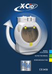
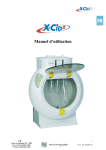
"Congratulations for purchasing your new iCare+ device"
iCare+ is an innovative Care & Maintenance system for the treatment of rotary dental devices (contra-angles,
straight handpieces, turbines) and dynamic dental devices (air scalers) with the following benefits :
-
ENGLISH
-
iCare+ insures cleaning-disinfection and lubrication of rotary and dynamic dental instruments
iCare+ treats the inner and outer surfaces of different instruments (contra-angles, straight handpieces,
turbines…)
Complete treatment of up to 4 instruments in 14 minutes
Up to 4 instruments can be treated simultaneously and automatically
Rotating port for contra-angles and straight handpieces guarantees the best possible cleaning, disinfection
and lubrication results
Validation and traceability ensured by embedded software
3 available treatment cycles : complete, partial, short
iCare+ Operation Manual 10-8-1
p. 2
TABLE OF CONTENTS
CHAPTER 1: SAFETY INSTRUCTIONS ____________________________________________ 5
1.1. Intended use and user _____________________________________________________________________ 5
1.1.1 Intended use ____________________________________________________________________________________ 5
1.1.2 User ___________________________________________________________________________________________ 5
1.2. General safety measures ___________________________________________________________________ 5
1.2.1. Adhesive safety labels ____________________________________________________________________________ 7
1.2.2. Position of safety labels ___________________________________________________________________________ 8
1.3. Individual safety measures _________________________________________________________________ 8
CHAPTER 2: DESCRIPTION OF iCare+ DEVICE _____________________________________ 9
2.1. Packaging contents________________________________________________________________________ 9
2.2. Description of iCare+ device _______________________________________________________________ 10
CHAPTER 3: USE of iCare+ DEVICE_____________________________________________ 13
3.1.1. Installing the iCare+ device _______________________________________________________________________ 13
3.1.2. Connecting the air supply _________________________________________________________________________ 13
3.1.3. Electrical connection ____________________________________________________________________________ 14
3.2. Implementation of the products ____________________________________________________________ 15
3.2.1. Positioning of n.Clean and n.Cid bottles Implementation of the products __________________________________ 15
3.2.2. Filling the oil tank _______________________________________________________________________________ 17
3.3 Validation test ___________________________________________________________________________ 18
3.3.1. On site validation test ____________________________________________________________________________ 18
3.3.2. Periodical validation test _________________________________________________________________________ 18
3.4. Connection of the instruments _____________________________________________________________ 18
3.4.1. Treated instruments _____________________________________________________________________________ 18
3.4.2. Installation of the instruments _____________________________________________________________________ 18
3.4.3. Removing the instruments _______________________________________________________________________ 20
3.5. Programming of iCare+ device ______________________________________________________________ 22
3.5.1. The Control panel _______________________________________________________________________________ 22
3.5.2. Connecting the instruments _______________________________________________________________________ 24
3.5.3. Selecting the program ___________________________________________________________________________ 24
3.5.4. Selecting the instruments_________________________________________________________________________ 24
3.5.5. Selecting the type of instrument ___________________________________________________________________ 25
3.5.6. Launching the cycle _____________________________________________________________________________ 27
CHAPTER 4: USER MAINTENANCE _____________________________________________ 29
4.1. General cleaning guidelines ________________________________________________________________ 29
4.2. General maintenance guidelines ____________________________________________________________ 29
4.2.1. Cleaning the treatment chamber ___________________________________________________________________ 30
4.2.2. Cleaning the external parts _______________________________________________________________________ 30
iCare+ Operation Manual 10-8-1
p. 3
ENGLISH
3.1. Setup __________________________________________________________________________________ 13
4.2.3. Emptying the used products of the drawer ___________________________________________________________ 30
4.2.4. Cleaning the drawer _____________________________________________________________________________ 31
4.2.5. Replacing the junction support blister _______________________________________________________________ 32
4.2.6. Replacing the o-ring joints of E-type connector _______________________________________________________ 32
4.2.7. Replacing the fuse of the supply inlet _______________________________________________________________ 33
CHAPTER 5: ERROR MESSAGES FROM OPERATING LIGHT INDICATORS _______________ 34
CHAPTER 6: TRACEABILITY __________________________________________________ 35
CHAPTER 7: TROUBLE SHOOTING _____________________________________________ 35
CHAPTER 8: BREAK-DOWN GUIDE ____________________________________________ 36
8.1. Error messages __________________________________________________________________________ 36
8.1.1. Liquid sensor ___________________________________________________________________________________ 36
8.1.2. Oil sensor _____________________________________________________________________________________ 36
8.1.3. Drawer sensor __________________________________________________________________________________ 36
8.1.4. Air sensor _____________________________________________________________________________________ 37
8.1.5. Door sensor ____________________________________________________________________________________ 38
8.2. Fatal error ______________________________________________________________________________ 38
CHAPTER 9: SPECIFICATIONS _________________________________________________ 39
9.2. Device classification ______________________________________________________________________ 39
9.3. Symbol Mark ___________________________________________________________________________ 40
CHAPTER 10: ACCESSORIES AND PART LIST _____________________________________ 41
CHAPTER 11: APPENDICES ___________________________________________________ 42
CE Certificate of Conformity ___________________________________________________________________ 42
EMC INFORMATION _________________________________________________________________________ 43
WARRANTY ________________________________________________________________________________ 45
iCare+ Operation Manual 10-8-1
p. 4
ENGLISH
9.1. Technical specifications: __________________________________________________________________ 39
CHAPTER 1: SAFETY INSTRUCTIONS
1.1. Intended use and user
1.1.1 Intended use
The iCare+ is an automatic decontamination system intended to be used for disinfecting invasive medical devices in
dentistry (soiled dynamic dental handpieces) prior to sterilization.
For this, iCare+ carries out four mandatory steps of a decontamination process, namely:
• Purge
• Cleaning
• Disinfection
• Lubrication
1.1.2 User
The iCare+ device is a product intended to be used only by qualified professionals from the dental field in medical
typed environments such as private clinics, hospitals, dental offices or else university laboratories.
The user is advised to comply with the following instructions:
The device must only be used in accordance with the instructions given in this user's manual in terms of
safety precaution and use of the system
The power supply of the location where iCare+ device will be used has to comply with IEC requirements and/
or with locally applicable regulations in force
The manufacturer, installer and importer are only responsible for the device's safety, reliability and performance if
the aforementioned points have been respected.
Prior to a written request, the manufacturer is able to provide a technical description, diagrams and test instructions
which he considers to be useful in order for an authorized skilled technician to repair and maintain the repairable
parts of the device.
IMPORTANT: Read this manual carefully before using your device. It contains
important information for the correct use of your iCare+ device
iCare+ Operation Manual 10-8-1
p. 5
ENGLISH
1.2. General safety measures
Caution symbol
This symbol is designed to catch the reader's attention to any text containing vital
safety information. You are asked to read closely and understand properly each of the
sections concerned immediately before using your iCare+ device
Information symbol
Text preceded by this symbol contains useful information for using your iCare+
device
The iCare+ device has been designed in accordance with current safety standards for similar devices. Despite this, it
is essential that a number of important safety measures have to be applied in order to avoid any potential incident
or even accident.
iCare+ Operation Manual 10-8-1
Use the iCare+ device only indoors
Do not install or use iCare+ device near a naked flame owing to the risk of
explosion
Do not install or use iCare+ device in direct contact with sunlight
Ensure that the iCare + device is placed in a ventilated place
Store iCare+ device at temperature between 0°C and 50°C and humidity rate
under 80%
Use iCare+ device in a temperate room (22-40°C)
Do not place n.Cid bottles near a heat source
Do not turn the device upside down
Place the device horizontally on a flat surface
Only use NSK products when operating iCare+ device (n.Clean as cleaning
product, n.Cid as disinfection product, NSK Oil as lubrication product)
During the installation of iCare+ device, leave a space of 5 cm free on each
side
Be sure that air supply pressure provided by iCare+ device is set between 5
and 6 bar
Do not remove the bottles (n.Clean or n.Cid) while iCare+ device is in use
If not using iCare+ device for a long period, switch of it and cut the air arrival
Only use NSK components for the maintenance of iCare+ device. The use of
different components may damage the device
p. 6
ENGLISH
These main safety requests have to be taken into consideration by the user.
1.2.1. Adhesive safety labels
Adhesive safety labels have been placed for iCare+ device on important locations. These include storage instructions
of the bottles and the device and information about the device's features.
The adhesive labels described below must be kept intact and should, if necessary, be
replaced with the substitution labels provided with the accessories. In order to avoid
damaging these labels, do not use abrasive products to clean your iCare+ device.
LA-2
LA-3
ENGLISH
LA-1
LA-4
LA-5
Figure 1: List of safety labels for iCare+ device
LA-1: NSK OIL label (product for lubrication)
LA-2: n.Clean label (product for cleaning)
LA-3: n.Cid label (product for disinfection)
LA-4: iCare+ device label with serial number
LA-5: Warning label about risk that may be caused by the needles
iCare+ Operation Manual 10-8-1
p. 7
1.2.2. Position of safety labels
The safety labels are glued on different parts of iCare+ device. The labels LA-1-2-3 are positioned on the internal
surface of the top cover and as for LA-4 it is placed on the bottom panel of the unit housing.
The label LA-5 is positioned near the housing for the bottles of products.
1.3. Individual safety measures
All the safety measures referenced below must be followed closely in order to prevent exposure to risks of the user.
iCare+ Operation Manual 10-8-1
Never handle the power cord with wet hands; risk of electrocution
CAUTION: NSK does not warrant the use of a power cord other than that
provided in the package.
Make sure the wall outlet has an earth connection with a differential
(breaker)
Be careful not to inject water into the device; fire risk as a result of short
circuits
Make sure to switch OFF the unit before any cleaning or maintenance
action; risk of electrocution
Do not attempt to dismantle any part of the device. In case of breakdown,
contact your retailer directly
In case of emission of smoke or a smell of burning, immediately switch off
the iCare+ device and contact your retailer directly
Do not use the iCare+ with flammable gases
ENGLISH
p. 8
CHAPTER 2: DESCRIPTION OF iCare+ DEVICE
2.1. Packaging contents
1
2
3
4
Article n°
1
2
3
4
5
Description
CD of installation with User Manual
Power cord
A 4/6 mm diameter tube for the pneumatic system
(length: 2 m) with “T” junction connector
iCare+ device
n.Clean, n.Cid, lubrication oil (Products not included
into iCare+ package. Must be ordered separately)
iCare+ Operation Manual 10-8-1
ENGLISH
5
Quantity
1
1
1
1
-
Upon delivery of the unit, please verify that the packaging has no damage
during shipment.
For shipment, always use the packaging of iCare+.
Keep the packaging away from children.
p. 9
2.2. Description of iCare+ device
Top cover for access to the housing of implementation of products: A
Treatment chamber with connection of instruments: B
Door for access to the treatment chamber: C
Removable drawer for collecting the soiled products: D
Control panel which enables the user to monitor the device: E
ENGLISH
G
F
Figure 2: Front panel of iCare+ device
Figure 3: Rear panel of iCare+ device
iCare+ Operation Manual 10-8-1
Power supply inlet: F
Air filter: G
p. 10
H
H
I
H
Figure 4: Top rear panel of iCare+ device + USB connection
Housing for the different products: H
USB connection: I
ENGLISH
iCare+ Operation Manual 10-8-1
p. 11
F
A'
E
D
1
2
3
6
4
6
A
B
C
A: Cycle selection button
ENGLISH
Figure 5: Control Panel of the iCare+ device
A': Operating light indicators (LEDs) for cycle selected
B: Ext w-o (or Spray) button for selection of the model of the handpiece(s)
C: Instruments selection and Oil volume button (Short or Long mode)
D: Start-up button. This button can also be used to stop the unit during cycle (with a long press).
E: Cycle progress operating light indicators (LEDs)
F: Warning operating light indicators (LEDs) for consumables state and for drawer, air, door state
1, 2, 3, 4: Indicator of the type of instrument (if the indicator is lit: instrument with external spray or without spray)
iCare+ Operation Manual 10-8-1
p. 12
CHAPTER 3: USE of iCare+ DEVICE
CAUTION: The use of controls, settings or the implementation of procedures other
than those specified below may expose users and patients to danger
3.1. Setup
3.1.1. Installing the iCare+ device
You should install the iCare+ device as requested below:
The device should be positioned on a flat, solid and level surface. The
maximum weight of the device, fully loaded, in conditions of use is 16 kg
The device should not be placed near a sink or any source that may splash it
The device should be placed in a room properly ventilated
The device should be kept away from any source of heat
Insert the air supply tube in the air filter: J, fixed on the Rear panel's device. Be sure that
the air tube is attached properly to the filter (see Figure 6). Connect the "T-shaped fast-on"
connector to the surgery compressor's air supply.
J
Figure 6: Connection of the tube in the
pneumatic system of iCare+ device
Following the norm EN ISO 7494-2, the air quality provided to iCare+ has to
iCare+ Operation Manual 10-8-1
be dry, clean and free from bacteria and contamination.
The pressure of the air supply should be between 5 and 6 bar
The minimum air flow level provided to the unit is 50 L./mn.
It is necessary to follow the above mentioned parameters in order to avoid
some dysfunctions or damage of the unit.
p. 13
ENGLISH
3.1.2. Connecting the air supply
AIR CONNECTION
iCare+ DEVICE
EXAMPLE OF CONNECTION
DENTAL UNIT
Cut off the air arrival. Connect
the tube coming from the unit
and from the iCare+ device on
the “T” connector. Connect
the compressor’s arrival on
the “T” connector
“T” CONNECTOR
AIR COMPRESSOR
ENGLISH
Figure 7: Connection of the iCare+ device to the air system
The pressure of the air supply must not be under 5 bar or above 6 bar. A
pressure sensor detects if the air pressure is too low or too high and stops
the machine. The operator is informed by an operating light indicator
positioned on the Control Panel.
Do not fold or deform the air supply tube
If you experience some difficulties during the connection step, please
contact your retailer
The air filter has an effective filter size of 5µm
3.1.3. Electrical connection
Connect the device by means of a power cord provided into the iCare+ package. This cable is
a Class I cable.
Just insert the power cord in the socket: K, on the iCare+ device's panel.
K
Figure 8: Electrical connection of
iCare+ device
iCare+ Operation Manual 10-8-1
p. 14
CAUTION: NSK do not warrant the use of other power cord than the one provided
with iCare+.
3.2. Implementation of the products
3.2.1. Positioning of n.Clean and n.Cid bottles Implementation of the products
ENGLISH
Start by opening the Top cover and take the bottles of n.Clean and n.Cid solutions supplied (see Figure 9).
Figure 9: n.Clean & n.Cid ready to be positioned on iCare+ device
iCare+ Operation Manual 10-8-1
CAUTION:
Keep the products in a cool dry place and well ventilated. Not exposed to
sunshine.
Avoid any contact with skin and eyes.
It is recommended to use protective glasses and gloves during handling of
bottles or during emptying of the waste drawer.
In case of contact with the eyes, rinse the eyes with water with the eyelids
open for a sufficient length of time, and then seek ophthalmological advice
immediately.
In case of contact with skin, wash off immediately with soap and water. In
case of skin reactions, seek medical advice.
In case of inhalation, move affected person into fresh air. In case of irritation
of the airways, seek medical advice.
If swallowed, rinse out mouth and then drink plenty of water. Do not induce
vomiting. Seek medical advice.
p. 15
CAUTION: Do not forget to remove the metallic cap on each bottle, before starting
the implementation of the consumables; you may damage the iCare+ device.
Figure 11: Implementation of
n.Cid bottle (500 mL)
Push the bottle of n.Clean solution into the correct housing (see Figure 10) and after that do the same thing with the
n.Cid solution bottle (see Figure 11). To insert the bottles, a short pressure on them is enough. It is not necessary to
push them strongly because they can be damaged.
For each bottle of solution or for the Oil, a coloured sticker is used to avoid
confusions between the products during the implementation of them:
For the n.Clean solution, a yellow sticker on its bottle and a yellow safety
adhesive label on its housing (of the Top rear panel) are glued
For the n.Cid solution, a grey sticker on its bottle and a grey safety adhesive
label on its housing (of the Top rear panel) are glued
The oil is directly poured into the tank (on the Top rear panel) on which a
blue safety adhesive label is glued
Always use n.Clean and n.Cid bottles supplied by NSK Europe GmbH.
The efficiency of the iCare+ device is optimized and certified for n.Clean and n.Cid
products.
Cleaning and disinfecting protocols have been calculated using these products.
The use of any other product may lead to a failure or damage of the iCare+ device or
of the instruments connected to, and the efficiency of the device will not be
ensured.
Therefore, in case of non compliance, the user will be considered as responsible.
CAUTION: When the bottles are not inserted, the needles, if reachable, can cause a
risk of injury
iCare+ Operation Manual 10-8-1
p. 16
ENGLISH
Figure 10: Implementation of
n.Clean bottle (500 mL)
3.2.2. Filling the oil tank
Shake well the maintenance Oil. Unscrew the tank's cap (see Figure 12) and pour the Oil in (see Figure 13). Please fill
the tank up to 20 mm from the top edge of the tank. After filling, screw its cap back on.
Figure 13: Filling the Oil tank of iCare+
device
ENGLISH
Figure 12: Unscrewing the Oil tank's cap
of iCare+ device
20 mm
Always use NSK Oil for handpiece in the iCare+ device to ensure optimal
operating conditions
After filling the tank, be sure to have properly closed its cap
Once the tank is filled and the cap properly attached, close the Top cover. After that you can start connecting the
different instruments.
iCare+ Operation Manual 10-8-1
p. 17
3.3 Validation test
3.3.1. On site validation test
This test must be performed prior to first start-up. It consists of a series of tests in order to validate that the
functioning parameters are functioning after the installation of iCare+.
3.3.2. Periodical validation test
NSK recommend to perform this periodical validation test every year, in order to validate that the performance of
iCare+ is still optimum.
3.4. Connection of the instruments
3.4.1. Treated instruments
The iCare+ device allows the cleaning and disinfection of internal and external surfaces of different instruments. The
main instruments intended to be treated are handpieces: contra-angles and turbines.
The different types of instruments that can be treated by iCare+ device are listed in the table 1 (please refer to the
part 3.3.5. Selecting the type of instrument).
3.4.2. Installation of the instruments
With the iCare+ device, it is possible to connect 2 kinds of instruments by means of 2 different connectors:
Air turbine connector for turbines.
E-type connector for contra-angles.
To connect a turbine with Midwest 4 holes(in accordance with the ISO 9168 standard) , start by opening the door
and connect the turbine directly to turbine connector of the iCare+ (see Figure 14) and screw the ring on tightly (see
Figure 15). Finish this operation by closing the door. Take care of the position of the turbine connector.
Do not use the door as a support : do not put anything on the door when open.
iCare+ Operation Manual 10-8-1
p. 18
ENGLISH
The iCare+ is a device whose function is to ensure the cleaning and disinfection of dental rotary and dynamic
instruments.
Figure 15: Screwing the ring on the Midwest
coupling
To connect a turbine with other connection type, it is necessary to install the corresponding adaptor first (Please
refer to the list of available adaptors into the chapter 10).
Insert the adaptor and screw the ring on firmly; check the positioning
of the different nozzles.
Figure 16: Change of turbine adaptor
It is necessary to use a specific iCare+ air turbine adaptor. These are especially
designed to deliver the right volume of product required for each instrument.
NSK does not guarantee a good working of the device with any other coupling.
iCare+ Operation Manual 10-8-1
p. 19
ENGLISH
Figure 14: Connection of one turbine
To connect a contra-angle or a hand piece on e-type connectors, in accordance with the ISO 3964 standard, start by
opening the door and connect the contra-angle on the E-type connector (see Figure 17). Finish this operation by
closing the door.
Figure 18: iCare+ version 1 with 1 air turbine
and 3 E-type connectors
ENGLISH
Figure 17: Connection of a contra-angle
Place properly the contra-angle in the connector until you hear a “click”. In
this way, the contra-angle will be well maintained during the different
phases of the treatment.
CAUTION:
Please make sure to remove any bur from the chuck
Make sure also to remove any support/holder for snap-on caps
If not the dirt and liquid inside the instrument could not come out
3.4.3. Removing the instruments
For removing an air turbine, in accordance with the ISO 9168 standard, follow the description below:
Once the cycle has finished, you will hear a "BIP" sound and the green operating light indicator ("END" LED) will be
lit, start opening the door. After that, remove the turbine from the connection.
iCare+ Operation Manual 10-8-1
p. 20
Removing a NSK turbine from its adaptor :
-
Move up the retaining ring of the adaptor.
Remove the turbine while maintaining the ring in upright position.
Retaining ring
Removing a Kavo turbine from its adaptor :
Remove the turbine by drawing down the instrument.
ENGLISH
-
iCare+ Operation Manual 10-8-1
The operation is identical to remove a turbine Sirona type of its
corresponding adapter.
p. 21
Removing a W&H turbine from its adaptor:
-
Move up the retaining ring of the adaptor.
Remove the turbine while maintaining the ring in upright position.
Retaining ring
ENGLISH
Removing a Bien-Air turbine from its adaptor:
- Press the button on the adapter.
- Remove the turbine while keeping the button pressed.
For removing a contra-angle, in accordance with the ISO 3964 standard, follow the description below:
Start opening the door. After that, remove the instrument in the axial direction of the E-type connector by pressing
on the release button.
3.5. Programming of iCare+ device
Start by putting the ON/OFF switch, localized on the Rear panel, on position I.
3.5.1. The Control panel
The Control panel (see Figure 19) is composed of a series of control buttons and also of light operating indicators
(LEDs).
The configuration of the device, the progress in the cleaning process and the status of the sensors are directly
displayed on the front panel using 25 LEDs. Combinations of the LEDs provide additional information such as the
progress in the copy of the internal memory into the USB key.
iCare+ Operation Manual 10-8-1
p. 22
A total of 7 switches are available. One switch: (labeled “Cycle”) is used to select one of the 3 types of cycle to run:
Full cycle (Cleaning + Disinfection + Lubrication), partial cycle (Cleaning + Lubrication) or short cycle (lubrication
only).
The "ext-WO” button enables the user to select the type of handpieces: a handpiece without spray or external spray,
or by default with an inner spray.
4 switches enable to select/deselect the instruments to be processed and the volume of lubricant to be used.
The “Start” switch is used to start the programmed cycle or as an emergency stop.
F
A'
E
D
2
3
6
4
6
A
ENGLISH
1
B
C
Figure 19: Control Panel of the iCare+ device's Front panel
A: Cycle selection button
A': Operating light indicators (LEDs) for cycle selected
B: Ext w-o (or Spray) button for selection of the model of the handpiece(s)
C: Instruments selection and Oil volume button (Short or Long mode)
D: Start-up button. This button can also be used to stop the unit during cycle (with a long press).
E: Cycle progress operating light indicators (LEDs)
F: Warning operating light indicators (LEDs) for consumables state and for drawer, air, door state
1, 2, 3, 4: Indicator of the type of instrument (if the indicator is lit: instrument with external spray or without spray)
iCare+ Operation Manual 10-8-1
p. 23
3.5.2. Connecting the instruments
The instruments have to been connected in accordance to the description done in part 3.2.2.
3.5.3. Selecting the program
The treatment of the instruments is achieved by a cycle composed of 3 different steps:
1 cleaning phase : 6 min (for 4 instruments)
1 disinfection phase : 6 min (for 4 instruments)
1 lubrication phase : 1.5 min (for 4 instruments)
The “CYCLE” button enables the operator to choose between the 3 maintenance cycles:
Full maintenance cycle: Cleaning/Disinfection/Lubrication
Partial maintenance cycle: Cleaning/Lubrication
Short maintenance cycle: Lubrication only (similar function as for Care3plus)
Full mode
Partial mode
ENGLISH
Short mode
Figure 20: Selection of the type of program for iCare+ device
A 4th pressure on the Cycle button manages the user to reset the choice of the cycle.
3.5.4. Selecting the instruments
By default, and as a measure of security, the iCare+ device dispenses the product to all the connectors. Here the
operator has to select the instrument(s) and choose the suitable Oil volume that he wants to be delivered:
Small drop corresponds to a normal volume (Short cycle)
Large drop corresponds to a specific volume for certain contra-angles (Long cycle for surgical contra-angle or
1:5 contra-angle for example)
2 unlit LEDs indicate that the instrument is deselected and so that no product will be sent through it
The volumes and the sequences of injection of n.Clean and n.Cid products are
directly programmed and monitored by the device itself, according to an accurately
defined and validated protocol by a medical institute.
iCare+ Operation Manual 10-8-1
p. 24
By default the Short cycle of oil is selected; press the button corresponding to the position where the instrument is
connected, once to select the Long cycle (large drop LED lit) and twice to deselect the instrument.
3.5.5. Selecting the type of instrument
In parallel, the user will be able to choose the type of instrument.
The iCare+ device is designed to enable the treatment of 2 models of dental rotary instruments:
Dental devices with only one drive channel
Dental devices with 2 channels: W/A + drive channels
All the different instruments that can be treated with iCare+ device are mentioned in the following table:
INSTRUMENT 1
ONLY
DRIVE
CHANNEL
W/A +
DRIVE
CHANNELS
(2
CHANNELS)
INSTRUMENT 2
INSTRUMENT 3
INSTRUMENT 4
Contra-angle or handpiece with external spray or without spray
Air turbine
Air Scaler
Contra-angle or handpiece with internal spray
ENGLISH
Table 1: List of different treatable instruments per model
Standard setting of iCare+ is designed for internal spray instruments. To make the selection for external or without
spray instrument, it is necessary to push simultaneously the “ext/WO button” and the button corresponding to the
position of the instrument without or external spray.
Button for
selection of
External/Without
spray instrument
For example to change the model of instrument 2, the operator will have to press simultaneously the button "ext
W/O” and the button 2; see on Figure 21 below. The LED "ext W/O", near button 2, is now lit to inform the operator
that the instrument 2 is an instrument without spray or with external spray.
iCare+ Operation Manual 10-8-1
p. 25
Figure 21: iCare+ device with lit W/O LEDs
In parallel of the function of external spray instrument, the unit can control if there is a mistake for the programming
of the button SPRAY or if a channel is blocked.
As a reverse case, if the user connects an instrument with external spray without using the button “ext W/O” (to
select external spray: “ext-w/o” LED), the unit is able to detect that the selection is wrong because this instrument
has external spray.
To inform the user of these problems, the unit will stop and the Air LED will blink, with a “BIP” signal heard. In
parallel, the concerning instrument is indicated by white LED blinking (oil indicator and/or ext-WO LEDs).
To restart the unit, first open the door, remove the instrument (to reduce the remaining pressure) reconnect the
instrument, and then close the door.
If the problem happens again, remove the handpieces and push the button “Start”.
Check the instruments (in case of possible blocked channels).
iCare+ Operation Manual 10-8-1
p. 26
ENGLISH
For example, if the user selects an instrument as an external spray instrument (but in reality, the instrument has an
internal spray), the unit is able to detect it.
3.5.6. Launching the cycle
Once the program is chosen, press START button to launch the cycle (see Figure 22).
START button allows starting the programmed cycle for the selected
instruments. If a problem happens, or that you wish to stop the unit during a
cycle, START button allows also stopping the unit by a long press.
The cycle is then stopped, the settings and selections are kept and the
machine stays on standby. By pressing again the START button, the cycle is
re-launched from the beginning with the same settings.
If the door is open while the unit is on standby, the settings and selections
are initialized.
ENGLISH
Figure 22: Launching the treatment cycle
If the user needs to stop the cycle during process, a long press on “START” button
will stop the unit.
A series of LEDs, positioned on the Control panel and on the treatment chamber, indicates the progress of the cycle:
Yellow LEDs are used to provide information of cleaning phase
White LEDs are used to provide information of disinfection phase
Blue LEDs are used to provide information of lubrication phase
Once the cycle completed, green LEDs ("END" LED + treatment chamber LED) are lit and inform the user that the
instruments are ready to be released from the unit.
iCare+ Operation Manual 10-8-1
When the “Mode” light indicator (small/big amount of Oil) is switched off,
the connection (1, 2, 3 or 4) is not selected
Just after purchasing iCare+ device, or after a long period of no use, run the
device empty (without instruments)
p. 27
CLEANING PHASE (X3) :
DISINFECTION PHASE (X1) :
LUBRICATION PHASE (X1) :
- Injection of n. Clean product inside the
instrument (W/A + body channels)
- Injection of n.Cid product inside the
instrument (W/A + body channels)
- Simultaneous injection of n.Clean
product outside the instruments
(external surfaces)
- SImultaneous injection of n.Cid
outsite the instruments (external
surfaces)
- Injection of Oil inside the
instrument (body of the
instrument)
- Action time of the liquid (30 s)
- Action time of the liquid (120 s)
- Air blowing time
- Air blowing time
iCare+ Operation Manual 10-8-1
In order to facilitate the external cleaning, we recommend using disinfectant
wipes (without protein fixation)for handling the instruments while
connecting them to the unit and rub slightly them before connecting in case
of important soils. It will help to liquefy the soils and stains located on the
outside surfaces.
At the end of the cycle, open the door and remove the instrument with a
disinfectant wipe (without protein fixation).
p. 28
ENGLISH
Figure 23: Treatment cycle of iCare+ device
CHAPTER 4: USER MAINTENANCE
There are two different types of maintenance that have to be distinguished; general maintenance, that is regularly
performed by the user and the specific maintenance performed by a skilled technician from NSK support.
Only skilled technician from NSK or people trained by NSK, are allowed to perform specific maintenance.
4.1. General cleaning guidelines
CAUTION : All the cleaning operations should be performed after having
disconnected the iCare+ device from the main power supply
Do not smoke in the room where the device is kept
Always use a soft cloth to clean the metallic and plastic parts of the device
Only use detergents that contain a very low level of alcohol (with no protein
fixation agent)
Never attempt to clean areas, that are difficult to access, with sharp objects
Be careful when cleaning the Control panel and never use aggressive
detergents
4.2. General maintenance guidelines
FREQUENCY / NUMBER OF CYCLES
Every
week
Every
week
2-3 times per
week
Every
week
1 year
When blown
OPERATION
PART
NUMBER
--
DESCRIPTION
50
Cleaning the treatment chamber
50
Cleaning the external parts
--
4.2.2.
15
Emptying the used products of the
drawer
Cleaning the drawer
--
4.2.3.
--
4.2.4.
S103205
On demand
4.2.5.
4.2.6.
50
Replacing the junction support blister
Replacing the fuse(s) of the supply inlet
4.2.1.
Table 2: Frequency of maintenance for iCare+ device
iCare+ Operation Manual 10-8-1
p. 29
ENGLISH
You should clean the iCare+ device as requested below:
4.2.1. Cleaning the treatment chamber
The treatment chamber can be easily cleaned, since the door is totally removable.
Thanks to the 2 spring-loaded tabs the door can be easily removed ensuring a
sufficient access to the chamber for the cleaning step.
After that, if necessary disconnect and remove the respective instruments that are
still implemented.
Use a soft cloth or a sponge to clean the chamber and after that to rinse it.
Proceed in the same way with the door.
We advise to use alcohol wipes for this part of the device.
It will ensure to remove with efficacy the possible drops of stains.
Spring-loaded tab
4.2.2. Cleaning the external parts
Clean the external parts with a soft cloth, as mentioned in the part 4.1. Do not use scouring agents or highly abrasive
products.
4.2.3. Emptying the used products of the drawer
The drawer should regularly be emptied. The emptying of the drawer is done after each
use, at the end of the day.
In parallel when the drawer is full, the corresponding LED on the Control panel is lit.
Tray + Drawer
Figure 25: Removal of the
drawer of iCare+ device
First of all start removing the drawer from its housing by sliding it backwards (see Figure 25) and secondly to dispose
of the used products, undo the clips to remove the tray from the drawer (see Figure 26).
iCare+ Operation Manual 10-8-1
p. 30
ENGLISH
Figure 24: Access to the treatment
chamber of iCare+ device
Figure 26: Removal of the tray clips and of the
drawer's tray
Figure 27: Tray and drawer after removal
All the products used for the treatment cycle of iCare+ device : Oil and especially the
n.Clean and n.Cid solutions are formulated to be disposed of in the sewage disposal
To avoid the creation of some residues or else to remove them, it is advised to clean regularly the drawer. According
to the table 2 of part 4.1, the frequency for tray's cleaning should be weekly.
To perform this step you have to proceed in 2 steps: first, remove the clips on both sides of the tray and then
remove the cover of the drawer (see Figure 27). After that you can clean it by means of alcohol wipes.
iCare+ Operation Manual 10-8-1
p. 31
ENGLISH
4.2.4. Cleaning the drawer
4.2.5. Replacing the junction support blister
The blister allows the collecting of the possible drops of products during its change; it had to be replaced
periodically.
As mentioned in the part 4.1. General cleaning guidelines, the frequency of replacement of the support junction
blister is 1 year.
First of all, open the top cover of iCare+ device to remove the soiled blister (see Figure 28), and then put directly the
new one on the support junction (by being sure that this last is properly sealed by means of the new blister).
ENGLISH
CAUTION: When removing the soiled blister, do not empty out the used products on
the iCare+ device, on the surface of its and on the floor.
Figure 28: Replacement of the junction support blister
4.2.6. Replacing the o-ring joints of E-type connector
Press the o-ring joint and remove it from the E-type connector (see Figure 29).
Thread the new o-ring joints in the corresponding grooves.
Figure 29: O-ring joints of E-type connector
iCare+ Operation Manual 10-8-1
p. 32
4.2.7. Replacing the fuse of the supply inlet
As mentioned in the part 4.1, the fuse(s) have to be changed if blown.
Press down simultaneously and pull the two tabs at the end of the fuse housing in order to unlock it. Remove and
replace the fuses according to their rating. Replace the fuses in the fuse box and insert them in their housing. Push
to lock (see Figure 30).
Remark:
The fuses should be replaced functions of the country of use; the specifications for each type of fuse are summarized
on the following table.
NATURE OF FUSE
EUROPE
VOLTAGE
230 V
AMPERE RATING
T1.6 AH 250V
For all the other maintenance operations of your iCare+ device, please contact immediately your NSK retailer.
iCare+ Operation Manual 10-8-1
p. 33
ENGLISH
Figure 30: Fuse box of iCare+ device
CHAPTER 5: ERROR MESSAGES FROM OPERATING LIGHT INDICATORS
Description of operating light indicators:
The different indicators and the Control panel are useful to inform the operator in real time about the operating
conditions of the iCare+ device.
B
D
C
E
F
A. “Cle” indicator informs the operator that n.Clean product level is too low.
Should this alarm occur the iCare+ device stops. It is necessary to replace the bottle by a new one in order to
restart the device. Remove the used bottle with a firm upward movement. To install a new bottle refer to
paragraph 3.2.1.1.
B. “Cid” indicator informs the operator that n.Cid product level is too low.
Should this alarm occur the iCare+ device stops. It is necessary to replace the bottle by a new one in order to
restart the device. Remove the used bottle with a firm upward movement. To install a new bottle, refer to
paragraph 3.2.1.1
C. “Oil” indicator informs the operator that the lubrication Oil product level is too low.
Should this alarm occur the iCare+ device stops. It is necessary to fill the oil tank. To fill the oil tank, refer to
paragraph 3.2.1.2.
After changing a bottle (n.Clean or n.Cid) or filling the Oil tank, press “Start” to prime the circuit.
D. “Drawer” indicator informs the operator about 2 things:
Either the drawer is not properly positioned (or even absent). In this case, check that the drawer is
present and correctly inserted.
Or the drawer is full and might overflow. In this case, remove the drawer and empty it.
In both cases, the iCare+ is unable to start the cycle.
E. This light indicator informs the operator that there is a problem with the air pressure (too low air pressure
value, no air, too high air pressure value). Air pressure plays an important role in the cycle efficacy; iCare+
device cannot start the cycle until the problem is not solved.
F. This light indicator informs the operator that the door is open or not properly closed. Close the door to start
any cycle.
iCare+ Operation Manual 10-8-1
p. 34
ENGLISH
A
iCare+ is equipped with a micro-processor which checks in real time every internal
component. If any problem is detected on one of the component, iCare+ device stops
immediately
CHAPTER 6: TRACEABILITY
The cleaning and disinfection phases have to be performed in accordance with the different current
recommendations. It is therefore necessary to enable the validation of the handpieces treatment done by the iCare+
device. That’s why traceability software must be used. The software “SoftCare+” was created to ensure the
traceability monitoring of the cycles realized by the device.
Please refer to specific user manual of annex software destined to visualize cycles information.
PROBLEM(S)
The device does not switch on
The device does not clean and/or
lubricate
The device does not clean and/or
lubricate correctly
iCare+ Operation Manual 10-8-1
POSSIBLE CAUSE(S)
Is the supply cord properly
connected to mains?
SOLUTION(S)
Connect the supply cord to
mains
Is the supply cord properly
connected to the iCare+ device?
Is the switch positioned on the "ON"
position?
Are the fuses working?
Is the door opened? (door LED lit)
Are the n.Clean or n.Cid level LEDs
lit?
Is the Oil level LED lit?
Insert properly the cord plug in
the device's main connector
Turn the main switch to "ON"
position
Change the fuses with the same
model
Push on one of the selection
cycles buttons
Close the door properly
Change the corresponding
bottle and prime
Fill the Oil tank
Is the air supply tube properly
connected to the device?
Connect properly the air supply
tube to the device's connector
Is the air supply pressure set
between 5 and 6 bar?
Is Short mode selected?
Is the instrument properly
connected to the connector?
Set the air supply pressure
between 5 and 6 bar
Select Long mode
Plug the instrument properly
Are the mode light indicators lit?
p. 35
ENGLISH
CHAPTER 7: TROUBLE SHOOTING
CHAPTER 8: BREAK-DOWN GUIDE
The other problems, not previously listed in the chapter 5 (Error messages from operating light indicators) and in the
chapter 7 (Possible failures), are explained in the following chapter.
8.1. Error messages
8.1.1. Liquid sensor
Corresponding LED is lit and a “BIP” signal can be heard. Please change the bottle and push “START” button to fill the
product line.
If the bottle is not empty, the sensor could have detected a bubble into the product line. Please push “START”
button to fill the product line.
ENGLISH
8.1.2. Oil sensor
Corresponding LED is lit and a “BIP” signal can be heard. Please open the oil tank and fill it with maintenance oil.
8.1.3. Drawer sensor
Corresponding LED is lit and a “BIP” signal can be heard. Remove the drawer and empty it. Or else, make sure that
the drawer is in appropriate position.
iCare+ Operation Manual 10-8-1
p. 36
8.1.4. Air sensor
With this air sensor there are 2 LED signals. Corresponding LED is lit constantly with “BIP” signal or corresponding
LED is blinking with “BIP” signal.
-
If corresponding LED is constantly lit and a “BIP” signal can be heard.
The air pressure is lower than 5 bar or higher than 6 bar.
To restart the unit, first, check the air pressure at the inlet of the machine. It is necessary to have between 5-6 bar at
the inlet. Once this is done, press “START” button to reset the error.
-
If “Air” LED is blinking with the LEDs around the buttons 1-2-3-4 (oil quantity selection + ext-WO) and a
“BIP” signal can be heard.
This measurement of dynamic air pressure is done to detect if channels are blocked.
This means 3 possibilities of alert:
Tube blocked inside the unit
Channel blocked inside the instrument
Wrong programming in case of use of ext-WO button for external spray instrument
ENGLISH
Tube blocked inside the unit:
The unit can detect if one of the tube inside the machine is blocked.
Blocked channel/External spray function:
The unit can detect if one of the channel of the instrument is blocked (spray channels or drive channels)
The iCare+ indicates the concerned instrument by blinking the oil quantity and ext-WO LEDs next to the
corresponding button (1-2-3-4)
In parallel of the function of external spray instrument, the unit can control if there is a mistake for the programming
of the ext-WO button.
Button for
selection of
External spray
/without spray
instrument
iCare+ Operation Manual 10-8-1
p. 37
For example, if the user selects an instrument as an external spray (but in reality, the instrument has an internal
spray), the unit is able to detect it.
As a reverse case, if the user connects an instrument with external spray without using the button SPRAY (to select
external spray: “ext-w/o” LED), the unit is able to detect that the selection is wrong because this instrument has
external spray.
Whatever the reason of the alert is (blocked channel or wrong selection), to restart the unit, it is first necessary to
check the reason of the problem. Then, open the door, disconnect the instruments and reconnect them. Finish by
closing the door.
Once this is done, push “START” button to reset the error. The “Air” LED should be switch off.
Check the instrument, if one of the channels is not blocked, and program the right selection (internal or external
spray instrument) by using the ext-WO button + the number of the instrument.
8.1.5. Door sensor
ENGLISH
Corresponding red LED “Door” is lit (No “BIP” signal).
Please, make sure that the door is properly closed.
8.2. Fatal error
The 6 red LEDs are blinking and 3 “BIP” sounds are heard.
If this case happens, please contact your retailer directly.
iCare+ Operation Manual 10-8-1
p. 38
CHAPTER 9: SPECIFICATIONS
9.1. Technical specifications:
ELECTRICAL SUPPLY
Power supply voltage: 230 V
Input frequency: 50 Hz
iCare+ DEVICE
Transportation and storage environment (humidity
rate):
Maximal altitude of use:
Use environment (atmospheric pressure range):
Transportation and storage environment (atmospheric
pressure range):
Mains voltage:
Power imput :
Pollution level
Dimensions overall:
Maximum space required:
Weight empty:
Maximum weight, fully loaded, in conditions of use:
Maximum heat output:
Maximum noise level:
Air pressure level :
Air filtration :
PRODUCTS
OTHERS
At temperate room 22-40°C
0-50°C
Specific maximal humidity of 80% for temperatures to
31°C, with a linear decrease to a specific humidity of 50%
at 40°C
10-80%
2000 m
700-1060 hPa
500-1060 hPa
Variation shall not be over +/- 10% of the nominal
voltage
50 VA
II
H: 405 mm / W: 355 mm / D: 400 mm
H: 455 mm / W: 455 / D: 450 mm
14 kg
16 kg
Not significant
< 60 dBA
ENGLISH
Use environment (working temperature):
Transportation and storage environment (storage
temperature):
Use environment (humidity rate):
>5 bar and <6 bar
5µm
500 mL packaged in a PEHD bottle to be pierced
500 mL packaged in a PEHD bottle to be pierced
Tank of 500 mL to be filled
Fully micro-processor driven and controlled (embedded
software)/Programming of the iCare+ device thanks to
an interface (Control panel)
9.2. Device classification
The iCare+ device belongs to the II b class in accordance with the rule 15 of the annex IX mentioned in the council
directive 93/42/EEC regarding medical devices.
iCare+ Operation Manual 10-8-1
p. 39
9.3. Symbol Mark
Mandatory conformance mark on many products placed on the market in the
European Economic Area
0535
Conforms to CE European Directive of “Medical equipment directive 93/42/EEC.”
(PATENT PENDING)
Manufacturer.
Follow the waste of electric and electronic equipment (WEEE) Directive
(2002/96/EC) for product and accessory disposal
Consult operation instructions.
Caution, Refer to attached instructions
For indoor use only.
ENGLISH
Use by
Keep Dry.
Lot number
Indication of the range of humidity level
Indication of pressure range
Indication of temperatures range
Indication of the year of manufacturing
Protective gloves recommended
Protective glasses recommended
iCare+ Operation Manual 10-8-1
p. 40
CHAPTER 10: ACCESSORIES AND PART LIST
The accessories and the spare parts for iCare+ device are respectively listed in the tables 3 and 4.
PRODUCT DESCRIPTION
n.Clean, 500 mL PEHD bottle (6pcs)
REFERENCE
ACL600
(not included into iCare+ package. Must be ordered separately)
n.Cid, 500 mL PEHD bottle (6pcs)
ACD600
(not included into iCare+ package. Must be ordered separately)
Maintenance Oil, 1 L PEHD bottle
Z016117
(not included into iCare+ package. Must be ordered separately)
iCare+ PTL Adaptor
Z1127010
(not included into iCare+ package. Must be ordered separately)
iCare+ KV Adaptor
Z1127011
(not included into iCare+ package. Must be ordered separately)
iCare+ SR Adaptor
Z1127012
(not included into iCare+ package. Must be ordered separately)
iCare+ WH Adaptor
Z1127013
(not included into iCare+ package. Must be ordered separately)
iCare+ BA Adaptor
Z1127014
(not included into iCare+ package. Must be ordered separately)
4/6 mm diameter tube
On demand
(1 piece included into iCare+ package)
Power Cord
On demand
CD of operation manual
ENGLISH
(1 piece included into iCare+ package)
On demand
(1 piece included into iCare+ package)
Table 3: List of accessories for iCare+ device
PRODUCT DESCRIPTION
E-type O-ring joint (Set of 4 pieces)
Blister pack
REFERENCE
Y900-185
S103205
Table 4: List of spare parts for iCare+ device
PTL Adaptor refers to adaptor(s) to use for the connection of NSK® air turbines for PTL-CL-4HV-T during the
treatment cycle.
KV Adaptor refers to adaptor(s) to use for the connection of KAVO® handpieces during the treatment cycle.
SR Adaptor refers to adaptor(s) to use for the connection of SIRONA
®
handpieces during the treatment cycle.
®
WH Adaptor refers to adaptor(s) to use for the connection of W&H handpieces during the treatment cycle.
BA Adaptor refers to adaptor(s) to use for the connection of BIEN-AIR® handpieces during the treatment cycle.
iCare+ Operation Manual 10-8-1
p. 41
CHAPTER 11: APPENDICES
CE Certificate of Conformity
The iCare+ device complies with the following standards:
61010-1 and 61010-2-040 standards: Safety requirements for electrical equipment for measurement, control
and laboratory use:
Part 1: General requirements,
Part 2-040: Particular requirements for sterilizers and washer-disinfectors used to treat
medical materials
This product has been granted CE labeling in accordance with European directive
(EN/93/42/CE) that is applicable to laboratory and more precisely to medical devices.
The number 0535 placed under the CE label refers to the notified organism which has
validated the product's conformity and so issued the certificate of conformity.
The head office responsible for the product is the following one:
iCare+ Operation Manual 10-8-1
ENGLISH
0535
NSK WT GmbH
Portitzer Straße 69d
D-04425 Taucha
GERMANY
p. 42
EMC INFORMATION
The iCare+ device complies with the following standards:
IEC 61326-1 standard: Electrical equipment for measurement, control and laboratory use-EMC
requirements; Part 1: General requirements
Guidance and manufacturer’s declaration - electromagnetic emissions
iCare+ device is intended for use in the electromagnetic environment specified below. The user of iCare+ should assure that is used in such an
environment.
Emissions test
Compliance
Electromagnetic environment - Guidance
RF Emissions EN 55011
RF Emissions EN 55011
Harmonics Emissions
EN 61000-3-2
Voltage fluctuations/
flicker emissions
EN 61000-3-3
Group 1
Class B
Class A
iCare+ should not cause any interference in nearby electronic equipment.
iCare+ is suitable for use in all establishments, including domestic establishments and those
directly connected to public low-voltage power supply network that supply network that
supplies buildings used for domestic purposes.
Complies
Guidance and manufacturer’s declaration - electromagnetics immunity
Immunity test
EN 61326-1 Test level
Compliance level
Electromagnetic environment - Guidance
Electrostatic
discharges (ESD)
EN 61000-4-2
Electrical fast transient
/ burst
EN 61000-4-4
+/- 4kV contact
+/- 4kV air
+/- 4kV contact
+/- 4kV air
+/- 1kV for power supply lines
+/- 1kV
Floors should be wood, concrete or ceramic tile. If
floors are covered with synthetic material, the
relative humidity should be at least 30%.
Mains power quality should be that of a typical
commercial or hospital environment.
Surge EN 61000-4-5
+/- 0.5kV line(s) to line(s)
+/- 1kV line(s) to earth
0% Ut during 10ms
0% Ut during 20ms
70% Ut during 200ms
0% Ut during 5 sec.
+/- 0.5kV line(s) to line(s)
+/- 1kV line(s) to earth
0% Ut during 10ms
0% Ut during 20ms
70% Ut during 200ms
0% Ut during 5 sec.
2 V/m
2 V/m
Voltage dips, short
interruptions and
voltage variations on
power supply input
lines
EN 61000-4-11
Magnetic field
EN 61000-4-8
Mains power quality should be that of a typical
commercial or hospital environment.
Mains power quality should be that of a typical
commercial or hospital environment.
If the user of iCare+ requires continued operation
during power mains interruptions, it is
recommended that the iCare+ be powered from an
uninterruptable power supply.
Power frequency magnetic fields should be at levels
characteristic of a typical location in a typical
commercial or hospital environment.
Guidance and manufacturer’s declaration - electromagnetic immunity
iCare+ device is intended for use in the electromagnetic environment specified below. The user of iCare+ should assure that is used in such an
environment.
Immunity test
Conducted RF
EN 61000-4-6
EN 61326-1 Test level
3V eff
150kHz to 80MHz
Compliance level
Electromagnetic environment - Guidance
3V rms
Portable and mobile RF communications equipment
should be used no closer to any part of iCare+ including
cables, than the recommended separation distance
calculated from the equation applicable to the frequency
of the transmitter.
Recommended separation distance
d = 1.2√P
d = 1.2√P de 80MHz à 800MHz
d = 2.3√P de 800MHz à 2.7GHz
iCare+ Operation Manual 10-8-1
p. 43
ENGLISH
iCare+ device is intended for use in the electromagnetic environment specified below. The user of iCare+ should assure that is used in such an
environment.
Radiated RF
EN 61000-4-3
3V /m
80MHz to 2.7GHz
3V/m
Where P is the maximum output power rating of the
transmitter in watts (W) according to the transmitter
manufacturer and is the recommended separation
distance in meters (m).
Field strengths from fixed RF transmitters are
determined by an electromagnetic site survey (a), should
be less than the compliance level in each frequency
range (b).
Interference may occur in the vicinity of equipment
marked with the following symbol :
NOTE 1 At 80MHz and 800MHz, the higher frequency range applies.
NOTE 2 These guidelines may not apply in all situations. Electromagnetic propagation is affected by absorption and reflection from structures,
objects and people.
Cables and accessories
Maximum length
Complies with
AC cord
2m
RF emissions
Harmonic emissions
Voltage fluctuations / flicker emission
Electrostatics discharges (ESD)
Electric fast transient / burst
Surge
Voltage dips, short interruptions and voltage variations on power supply input lines
Magnetic fields
Conducted RF
Radiated RF
EN 61000-3-2
EN 61000-3-3
EN 61000-4-2
EN 61000-4-4
EN 61000-4-5
EN 61000-4-11
EN 61000-4-8
EN 61000-4-6
EN 61000-4-3
Recommended separation distance between portables and mobile RF communications equipment and the iCare+
iCare+ is intended for use in an electromagnetic environment in which radiated RF disturbances are controlled. The user of iCare+ can help
prevent electromagnetic interference by maintaining a minimum distance between portable and mobile RF communications equipment and
the iCare+ as recommended below, according to the maximum output power of the communications equipment.
Separation distance according to frequency of transmitter
Rated maximum output power
m
of transmitter
150kHz to 80MHz
80MHz to 800MHz
800MHz to 2.5GHz
W
0.001
0.01
1
10
100
d=1.2√P
0.12
0.38
1.2
3.8
12
d=1.2√P
0.12
0.38
1.2
3.8
12
d=2.3√P
0.23
0.73
2.3
7.3
23
For transmitter rated at a maximum output power not listed above, the recommended separation distance « d » in meters (m) can be
estimated using the equation applicable to the frequency of the transmitter, where « P » is the maximum output power rating of the
transmitter in watts (W) according to the transmitters manufacturer.
NOTE 1 At 80 Mhz and 800Mhz, the separation distance for the higher frequency is applicable.
NOTE 2 These guidelines may not apply in all situations. Electromagnetic propagation is affected by absorption and reflection from structures,
objects and people.
iCare+ Operation Manual 10-8-1
p. 44
ENGLISH
a Field strengths from fixed transmitters, such as base stations for radio (cellular/cordless) telephones and land mobiles
radios, amateur radio, AM and FM radio broadcast and TV broadcast cannot be predicted theoretically with accuracy. To assess
the electromagnetic environment due to fixed RF transmitters, an electromagnetic site survey should be considered. If the
measured field strength in the location in which iCare+ is used exceeds the applicable RF compliance level above, the iCare+
should be observed to verify normal operation. If abnormal performance is observed, additional measures may be necessary,
such as reorienting or relocating the iCare+.
b Over the frequency range 150kHz to 80MHz, field strengths should be less than 3V/m.
WARRANTY
The manufacturer will warrant the quality of the product for one year after you purchased it, against manufacturing
errors and defects in equipment under conditions of normal installation and use and of after-sales monitoring. NSK
reserves the right to analyze and determine the cause of any problem. The parts considered as consumables are not
covered by the manufacturer’s warranty.
ENGLISH
Note, however, that if you did not observe what is written in this operation manual or for any consumables or
recommended liquids, the warranty will not apply.
iCare+ Operation Manual 10-8-1
p. 45
ENGLISH
NSK Europe GmbH
NSK France
NSK Dental Spain SA
NSK United Kingdom Ltd
Elly-Beinhorn-Strasse 8,
65760 Eschborn,
Germany
Tel: +49 (0) 6196 77606-0
Fax: +49 (0) 6196 77606-29
32, rue de Lisbonne
75008 Paris,
France
Tel: +33 (0)1 56 79 59 80
Fax: +33 (0)1 56 79 59 81
www.nsk-europe.de/
[email protected]
http://www.nsk.fr
[email protected]
C/ Módena, 43
El Soho - Európolis
28232 Las Rozas,
Madrid,
Spain
Tel: +34-91-626-61-28
Fax: +34-91-626-61-32
Office 5, Gateway 1000,
Arlington Business Park,
Whittle Way, Stevenage,
Hertfordshire, SG1 2 FP
Tel: 0800 634 1909
Tel Intl: +44 (0)1438 310 670
Fax: 0800 634 1910
Fax Intl: +44 (0)1438 310 671
[email protected]
http://www.nsk-spain.es
NSK WT GmbH
Portitzer Straße 69d
D-04425 Taucha
GERMANY
http://www.nsk-uk.com
Specifications are subject to change without notice
iCare+ Operation Manual 10-8-1
p. 46
« Félicitations pour l'acquisition de votre nouvel iCare+ »
iCare+ est un système innovant dont la fonction est d'assurer le traitement d'instruments dynamiques dentaires
(contre-angles, turbines). Ses avantages sont nombreux :
-
FRANCAIS
-
iCare+ assure le nettoyage-désinfection et la lubrification d’instruments dentaires dynamiques
L’appareil iCare+ permet le traitement des surfaces internes et externes des surfaces des différents
instruments (contre-angles, turbines…)
Un traitement complet en moins de 14 minutes.
4 instruments peuvent être traités simultanément et automatiquement
La transmission rotative nettoie, désinfecte et lubrifie de manière plus efficace les contre-angles.
Validation et traçabilité assurées par le logiciel embarqué
3 types de traitement sont disponibles : complet, partiel, court
iCare+ Manuel Utilisateur 10-8-1
p. 1
TABLE DES MATIERES
CHAPITRE 1 : CONSIGNES DE SECURITE _________________________________________ 4
1.1.
Usage attendu et Utilisateur ______________________________________________________________ 4
1.1.1 Usage attendu : __________________________________________________________________________________ 4
1.1.2 Utilisateur :______________________________________________________________________________________ 4
1.2. Mesures générales de sécurité ______________________________________________________________ 4
1.2.1. Etiquettes adhésives de sécurité ____________________________________________________________________ 6
1.2.2. Positionnement des étiquettes de sécurité ____________________________________________________________ 7
1.3. Mesures individuelles de sécurité ____________________________________________________________ 7
CHAPITRE 2 : DESCRIPTION DE L'iCare+ _________________________________________ 8
2.1. Contenu de l’emballage ____________________________________________________________________ 8
2.2.
Description de l'appareil iCare+ ___________________________________________________________ 9
CHAPITRE 3 : UTILISATION DE L'iCare+ _________________________________________ 11
3.1.1. Installation de l'appareil iCare+ ____________________________________________________________________ 11
3.1.2. Connexion au système pneumatique (air) ____________________________________________________________ 11
3.1.3. Connexion au réseau électrique____________________________________________________________________ 12
3.2. Mise en place des produits ________________________________________________________________ 13
3.2.1. Positionnements des bouteilles de n.Clean et de n.Cid _________________________________________________ 13
3.2.2. Remplissage du réservoir d'huile ___________________________________________________________________ 15
3.3. Test de validation ________________________________________________________________________ 16
3.3.1. Test de validation sur site _________________________________________________________________________ 16
3.3.2. Test de validation périodique______________________________________________________________________ 16
3.4. Mise en place des instruments _____________________________________________________________ 16
3.4.1. Instruments traités ______________________________________________________________________________ 16
3.4.2. Connexion des instruments _______________________________________________________________________ 16
3.4.3. Extraction des instruments________________________________________________________________________ 18
3.5. Programmation de l'appareil iCare+ _________________________________________________________ 20
3.5.1. Le panneau de contrôle __________________________________________________________________________ 20
3.5.2. Connexion des instruments _______________________________________________________________________ 22
3.5.3. Sélection du programme _________________________________________________________________________ 22
3.5.4. Sélection des instruments ________________________________________________________________________ 22
3.5.5. Sélection du type d'instrument ____________________________________________________________________ 23
3.5.6. Lancement du cycle _____________________________________________________________________________ 25
CHAPITRE 4: MAINTENANCE DE L'UTILISATEUR __________________________________ 27
4.1. Recommandations générales pour le nettoyage _______________________________________________ 27
4.2. Recommandations générales pour l'entretien _________________________________________________ 27
4.2.1. Nettoyage de la chambre à instruments _____________________________________________________________ 28
4.2.2. Nettoyage des parties extérieures __________________________________________________________________ 28
iCare+ Manuel Utilisateur 10-8-1
p. 2
FRANCAIS
3.1. Mise en service __________________________________________________________________________ 11
4.2.3. Vidage des produits usés du tiroir __________________________________________________________________ 28
4.2.4. Nettoyage du tiroir ______________________________________________________________________________ 29
4.2.5. Changement du blister de protection du support jonction ______________________________________________ 29
4.2.6. Remplacement des joints toriques du connecteur E-type _______________________________________________ 30
4.2.6. Remplacement du (des) fusible(s) du bloc secteur _____________________________________________________ 31
CHAPITRE 5 : MESSAGES D’ERREURS DES INDICATEURS LUMINEUX _________________ 32
CHAPITRE 6 : TRACABILITE___________________________________________________ 33
CHAPITRE 7 : RESOLUTION DES PROBLEMES ____________________________________ 33
CHAPITRE 8 : GUIDE DE DEPANNAGE __________________________________________ 34
8.1. Erreur normale __________________________________________________________________________ 34
8.1.1. Capteurs des liquides (n.Clean et n.Cid) _____________________________________________________________ 34
8.1.2. Capteur d’huile _________________________________________________________________________________ 34
8.1.3. Capteur tiroir __________________________________________________________________________________ 34
8.1.4. Capteur d’air ___________________________________________________________________________________ 34
8.1.5. Capteur porte __________________________________________________________________________________ 36
8.2. Erreur fatale ____________________________________________________________________________ 36
CHAPITRE 9 : SPECIFICATIONS ________________________________________________ 37
9.2. Classification de l’appareil _________________________________________________________________ 37
9.3. Symboles_______________________________________________________________________________ 38
CHAPITRE 10 : ACCESOIRES ET PIECES DE RECHANGE _____________________________ 39
CHAPITRE 11 : ANNEXES ____________________________________________________ 40
Certificat CE de conformité ____________________________________________________________________ 40
INFORMATION CEM _________________________________________________________________________ 41
GARANTIE _________________________________________________________________________________ 44
iCare+ Manuel Utilisateur 10-8-1
p. 3
FRANCAIS
9.1. Caractéristique générales _________________________________________________________________ 37
CHAPITRE 1 : CONSIGNES DE SECURITE
1.1.
Usage attendu et Utilisateur
1.1.1 Usage attendu :
ICare+ est un système automatique de décontamination l’usage attendu est de désinfecter des dispositifs médicaux
employés en dentisterie considérés comme invasifs (pièces à main dentaires dynamiques) avant stérilisation.
Pour cela, iCare+ effectue quatre étapes obligatoires dans le processus de décontamination, à savoir :
· Purge
· Nettoyage
· Désinfection
· Lubrification
1.1.2 Utilisateur :
L’appareil iCare+ est un produit destiné à tous les professionnels qualifiés du secteur dentaire dans des
environnements de type médical tels que les cabinets dentaires, les hôpitaux, les cliniques privées, ou encore les
laboratoires universitaires.
Il est conseillé à l'utilisateur de se conformer avec les instructions suivantes :
L'appareil doit être utilisé conformément aux instructions fournies dans ce manuel utilisateur en termes de
mesures de sécurité et pour l'utilisation du système
L'alimentation électrique de la pièce où l'appareil iCare+ sera utilisé doit être conforme aux régulations de la
CEI, ou avec les régulations locales en vigueur.
Le fabricant, l'installateur et l'importateur sont les seuls responsables de la sécurité, de la fiabilité et de la
performance de l'appareil si les points mentionnés ci-dessus ont été respectés.
Avant une demande écrite du client, le fabricant est capable de fournir la description technique, les courbes et les
instructions pour le test qu'il considère utile pour permettre l'intervention (réparation, maintenance) d'un technicien
qualifié sur les pièces réparables de l'appareil iCare+.
IMPORTANT : Lire le manuel utilisateur avant d’utiliser l’appareil. Il contient des
informations importantes pour une utilisation correcte de votre appareil iCare+.
iCare+ Manuel Utilisateur 10-8-1
p. 4
FRANCAIS
1.2. Mesures générales de sécurité
Symbole attention
Ce symbole est destiné à attirer l'attention du lecteur sur quelque texte contenant
des informations liées à la sécurité. Il vous est demandé de lire attentivement et de
comprendre correctement chaque section concernée avant l'utilisation de votre
appareil iCare+
Symbole information
Le texte précédé par ce symbole contient des informations utiles à l'utilisateur pour
l'utilisation de l'appareil iCare+
iCare+ Manuel Utilisateur 10-8-1
Utiliser l’appareil iCare+ uniquement en intérieur
Ne pas installer ou utiliser l'appareil iCare+ à proximité d'une flamme nue
qui pourrait causer une explosion
Ne pas installer ou utiliser sous exposition directe au soleil.
S'assurer que l'appareil iCare+ est placé dans un endroit ventilé
Stocker l'appareil iCare+ à une température comprise entre 0°C et 50°C et à
un taux d'humidité ne dépassant pas 80%
Utiliser l’appareil iCare+ dans une pièce tempérée (22-40°C)
Ne pas placer les bouteilles de n.Cid à proximité d'une source de chaleur
Ne pas retourner l'appareil.
Placer l’appareil horizontalement sur une surface plane
Utiliser uniquement les produits NSK lorsque vous utilisez l'appareil iCare+
(n.Clean comme produit de nettoyage, n.Cid comme produit de
désinfection, Huile NSK comme produit de lubrification)
Pendant l'installation de l'appareil iCare+, laisser un espace de 5 cm de
chaque côté.
S’assurer que la pression d’air fournie à l’iCare+ est comprise entre 5 et 6
bar
Vérifier que la tension d’alimentation correspond bien à la plage indiquée
par la plaque signalétique de la machine
Ne pas enlever les bouteilles (n.Clean ou n.Cid) pendant que l'appareil
iCare+ est en cours d'utilisation
En cas de non utilisation prolongée de l'appareil iCare+, l'éteindre et couper
l'arrivée d'air
Utiliser uniquement les composants NSK pour la maintenance de l'appareil
iCare+. L'utilisation de composants différents pourrait endommager
l'appareil
p. 5
FRANCAIS
Lees principales consignes de sécurité, décrites ci-dessous, doivent être prises en considération par l’utilisateur.
1.2.1. Etiquettes adhésives de sécurité
Les étiquettes de sécurité adhésives ont été placées sur l'appareil iCare+ à des endroits stratégiques. Ces dernières
présentent des informations pour l'utilisateur tant sur les conditions de stockage que sur les caractéristiques de
l'appareil.
Les étiquettes adhésives décrites ci-dessous doivent rester intactes et, si nécessaire,
être remplacées par les étiquettes de substitution avec les accessoires. Afin d'éviter
la détérioration de ces étiquettes, ne pas employer de produits abrasifs pour
nettoyer votre appareil iCare+
La figure 1 décrit chaque type d'étiquette collée sur l'appareil iCare+.
ET-2
ET-3
FRANCAIS
ET-1
ET-4
ET-5
Figure 1 : Liste des étiquettes de sécurité de l'appareil iCare+
ET-1 : Etiquette pour l'huile NSK (produit pour la lubrification)
ET-2 : Etiquette n.Clean (produit pour le nettoyage)
ET-3 : Etiquette n.Cid (produit pour la désinfection)
ET-4 : Etiquette d’information de l'appareil iCare+ avec numéro de série
ET-5 : Etiquette d’avertissement de risque lié aux aiguilles
iCare+ Manuel Utilisateur 10-8-1
p. 6
1.2.2. Positionnement des étiquettes de sécurité
Les étiquettes de sécurité sont collées à différents endroits de l'appareil iCare+. Les étiquettes ET-1-2-3 sont
positionnés sur la surface intérieure du capot supérieur et quant à l'étiquette ET-4 elle est placée sur la tôle basse du
boitier tôle.
L’étiquette ET-5 est placée à coté des logements pour les flacons de produits
1.3. Mesures individuelles de sécurité
L'ensemble des mesures de sécurité référencées ci-dessous doivent être suivies scrupuleusement afin d'éviter toute
exposition aux risques de l'utilisateur.
iCare+ Manuel Utilisateur 10-8-1
Ne jamais manipuler le câble d'alimentation avec les mains humides; risque
d'électrocution
ATTENTION : NSK ne garantit pas l’utilisation d’un autre cordon que celui
fourni dans l’emballage.
Assurez-vous que la prise murale comporte bien une terre munie d’un
différentiel (disjoncteur)
Réaliser les opérations de nettoyage et d’entretien en s’assurant que la
machine est hors tension. Ceci afin d’éviter tout risque d’électrocution.
Faites attention à ne pas injecter de l'eau dans l’appareil; risque d'incendie
suite à un court circuit
Ne pas essayer de démonter aucune partie de l’appareil. En cas de panne
contacter directement votre revendeur
En cas d'émission de fumée ou de dégagement d'une odeur de brulé,
éteignez immédiatement l'appareil iCare+ et contacter directement votre
revendeur
L’appareil ne doit pas être utilisé en présence de gaz inflammable.
FRANCAIS
p. 7
CHAPITRE 2 : DESCRIPTION DE L'iCare+
2.1. Contenu de l’emballage
1
2
3
4
Article n°
1
2
3
4
5
Description
CD d'installation avec Manuel Utilisateur
Câble d'alimentation
Tube de φ 4-6 mm pour le raccordement en air
(longueur : 2 m) muni d’un connecteur rapide en
"T"
Appareil iCare+
n.Clean, n.Cid, Huile de lubrification (produits noninclus dans l’emballage. Doivent être commandés
séparemment).
iCare+ Manuel Utilisateur 10-8-1
FRANCAIS
5
Quantité
1
1
1
1
-
A réception de l’appareil, veuillez vérifier que l’emballage n’a subi aucun
dommage lors du transport.
Pour le transport, toujours utiliser l’emballage d’origine de l’appareil.
Conserver les emballages d’origine hors de portée des enfants
p. 8
2.2.
Description de l'appareil iCare+
Capot supérieur pour accès au logement pour les produits: A
Chambre de traitement avec la connexion des instruments: B
Porte pour l’accès à la chambre de traitement: C
Tiroir amovible pour la collecte des produits usagés : D
Panneau de contrôle permettant à l'utilisateur de programmer l'appareil : E
FRANCAIS
G
F
Figure 3 : Panneau arrière de l’appareil
iCare+
Figure 2 : Face avant de l’appareil iCare+
Alimentation secteur : F
Filtre à air : G
H
H
I
H
Logement pour les différents produits : H
Connexion USB : I
Figure 4 : Panneau arrière de l’appareil iCare+ avec port USB
iCare+ Manuel Utilisateur 10-8-1
p. 9
F
A'
E
D
1
2
3
6
4
6
A
B
C
A : Bouton de sélection du cycle
FRANCAIS
Figure 5 : Panneau de contrôle de l'appareil iCare+
A': Indicateurs lumineux (LEDs) pour le cycle sélectionné
B : Bouton Ext w-o (ou sélection spray interne ou externe) pour la sélection du modèle de pièce(s) à main
C : Bouton de sélection des instruments et du volume d'huile (Mode Court ou Long)
D : Bouton de mise en marche. Sert également pour arrêter la machine en cours de cycle par un appui long.
E : Indicateurs lumineux sur l'avancement et le statut du cycle
F : Indicateurs lumineux pour l'état des consommables et du tiroir, de l'air et de la porte
1, 2, 3, 4 : Indicateur du type d’instrument (si LED allumée l’instrument avec spray externes/ou sans spray)
iCare+ Manuel Utilisateur 10-8-1
p. 10
CHAPITRE 3 : UTILISATION DE L'iCare+
ATTENTION : L'utilisation de commandes, de réglages ou de procédures autres que
celles décrites ci-dessous pourraient exposer les utilisateurs et les patients à des
dangers
3.1. Mise en service
3.1.1. Installation de l'appareil iCare+
Vous devez installer l'appareil iCare+ comme recommandé ci-dessous :
Cet appareil doit être positionné sur une surface plane, solide et stable. Le
poids maximal de l'appareil, à charge pleine, en conditions d'utilisation est
de 16 kg
L'appareil ne doit pas être positionné à proximité d'un évier ou de
quelconque source qui pourrait causer des éclaboussures
L'appareil doit être placé dans une pièce correctement ventilée
L'appareil doit être tenu à l'écart d'une source de chaleur
FRANCAIS
3.1.2. Connexion au système pneumatique (air)
Connecter le connecteur rapide en «T» sur l'arrivée du compresseur et après ça connecter
votre appareil. Insérer le tube d'arrivée d'air du cabinet dentaire dans le filtre à air : J, fixé
sur le panneau arrière de l'appareil. Assurez-vous que le tuyau d'air est fixé correctement
au filtre (voir Figure 6).
J
Figure 6 : Connexion du tube au système
pneumatique de l'appareil iCare+
iCare+ Manuel Utilisateur 10-8-1
Suivant le norme EN ISO 7494-2, il est nécessaire de se connecter à un
réseau d’air de qualité dentaire, sec, propre et non contaminé.
La pression d’air fournie doit être comprise entre 5 et 6 bar.
Le débit d’air minimum doit être de 50 L./mn.
Il est nécessaire de respecter les paramètres ci-dessus afin d’éviter tout
dysfonctionnement ou dommage de la machine.
p. 11
CONNEXION D’AIR
APPAREIL iCare+
EXEMPLE DE CONNECTION
UNIT DENTAIRE
Couper le tuyau d’air.
Connecter le tuyau venant de
l’unit et de l’appareil iCare+
sur le connecteur rapide en T.
Connecter l’arrivée
compresseur sur le
connecteur rapide T.
CONNECTEUR
RAPIDE EN “T”
AIR COMPRESSEUR
FRANCAIS
Figure 7 : Connexion de l’appareil iCare+ au système pneumatique
La pression ne doit pas être inférieure à 5 bar et supérieure à 6 bar. Le
capteur de pression, lorsqu'il détecte une pression trop faible ou trop
élevée, stoppe la machine. L'opérateur est informé par un indicateur
lumineux situé sur le panneau de contrôle.
Ne pas plier ou déformer le tube d'arrivée d'air
Si vous éprouvez certaines difficultés durant l'étape de connexion, veuillez
contacter votre revendeur
Le filtre à air a une précision de filtration de 5µm
3.1.3. Connexion au réseau électrique
Connecter l'appareil au réseau électrique au moyen du cordon d'alimentation fourni dans
l’emballage. Ce cordon secteur est un câble de Classe I relié à la terre.
Enficher simplement le cordon dans la prise K, à l'arrière de l'appareil.
K
Figure 8 : Connexion de l'appareil
iCare+ au réseau électrique
iCare+ Manuel Utilisateur 10-8-1
p. 12
ATTENTION : NSK ne garantit pas l’utilisation d’un autre cordon que celui fourni
dans l’emballage.
3.2. Mise en place des produits
3.2.1. Positionnements des bouteilles de n.Clean et de n.Cid
FRANCAIS
Commencez par ouvrir le capot supérieur et prenez les bouteilles de n.Clean et n.Cid fournies (voir Figure 9).
Figure 9 : n.Clean & n.Cid prêts à être positionnés sur le support jonction de l’appareil iCare+
ATTENTION : Conserver les produits dans un endroit frais et bien ventilé, à l’abris de
l’exposition directe au soleil.
Eviter tout contact avec la peau ou les yeux.
Il est recommandé de porter des lunettes ou des gants de protection lors de
la manipulation des flacons, des instruments souillés ainsi que pendant les
opérations de vidage des produits usagés.
En cas de contact avec les yeux, rincer abondamment à l’eau en maintenant
les paupières ouvertes. Consulter immédiatement un spécialiste.
En cas de contact avec la peau, nettoyer immédiatement avec de l’eau et du
savon. En cas d’irritation, demandez conseil à un médecin.
En cas d’inhalation, placer la personne affectée à l’air frais. En cas d’irritation
des voies respiratoires, demandez conseil à un médecin.
En cas d’absorption, rincer la bouche et boire ensuite beaucoup d’eau. Ne
pas forcer à régurgiter. Demander conseil à un médecin.
ATTENTION : Ne pas oublier de retirer la protection métallique, détachable sur
chaque bouteille, avant de commencer l'installation des consommables, vous
pourriez endommager l'appareil iCare+.
iCare+ Manuel Utilisateur 10-8-1
p. 13
Figure 10 : Connexion de la
bouteille de n.Clean (500 mL)
Figure 11 : Connexion de la
bouteille de n.Cid (500 mL)
Les flacons doivent être enfoncés jusqu’à venir en butée dans le fond du logement. Pour cela, une légère pression
est nécessaire pour l’insertion complète du flacon. Il n’est pas nécessaire d’appuyer fortement car une pression trop
forte pourrait endommager l’appareil.
Pour chaque bouteille de solution ou pour l'Huile, une étiquette colorée est utilisée
pour éviter les confusions de l'utilisateur pendant leur installation :
Pour la solution de n.Clean, une étiquette jaune sur la bouteille et une
étiquette adhésive de sécurité sur son logement (du support jonction) sont
collées
Pour la solution de n.Cid, une étiquette grise sur la bouteille et une étiquette
adhésive de sécurité sur son logement (du support jonction) sont collées
L'huile est directement versée dans le réservoir (sur le support jonction) sur
lequel une étiquette adhésive de sécurité bleue est collée
Toujours utiliser les bouteilles de n.Clean et de n.Cid fournies par NSK Europe GmbH.
L'efficacité de l'appareil iCare+ est optimisée et certifié avec les produits n.Clean et
n.Cid.
Les protocoles de nettoyage et de désinfection ont été mis au point sur la base de
ces produits.
L'utilisation de quelconque autre produit pourrait amener à une mise en erreur voire
à un endommagement de l'appareil iCare+ ou de l'un des instruments connectés à ce
dernier, et même l’efficacité de ce dernier ne serait plus assurée.
Par conséquent en cas de non respect l'utilisateur sera tenu comme responsable.
iCare+ Manuel Utilisateur 10-8-1
p. 14
FRANCAIS
Percuter la bouteille de solution de n.Clean dans le bon logement (voir Figure 10) et faites ensuite la même chose
avec la bouteille de n.Cid (voir Figure 11).
ATTENTION : Lorsque les flacons ne sont pas insérés, les aiguilles de perçage sont
accessibles et peuvent présenter un risque de blessure.
3.2.2. Remplissage du réservoir d'huile
Figure 12 : Dévissage du bouchon du
réservoir d'huile de l'appareil iCare+
FRANCAIS
Commencer par bien agiter l'huile NSK. Dévisser le bouchon du réservoir (voir Figure 12) et versez-y l'huile (voir
Figure 13). Après avoir rempli le réservoir, revissez le bouchon.
Figure 13 : Remplissage du réservoir
d'huile de l'appareil iCare+
20 mm
Toujours utiliser l'huile de maintenance NSK pour la lubrification des pièces à
main afin d’assurer des conditions d'utilisation optimales
Après le remplissage du réservoir, assurez-vous d'avoir correctement
refermé le bouchon
Une fois que le réservoir est rempli et le bouchon correctement revissé, fermer le capot supérieur. Ensuite vous
pouvez commencer à connecter les différents instruments.
iCare+ Manuel Utilisateur 10-8-1
p. 15
3.3. Test de validation
3.3.1. Test de validation sur site
Ce test doit être effectué avant la première mise en service. Il comporte une série de tests afin de valider que les
paramètres de fonctionnement sont bien respectés suite à l’installation de l’iCare+.
Ce test sera effectué par l’installateur de votre iCare+ (personne agréée par NSK ou personnel formé de chez NSK).
3.3.2. Test de validation périodique
Il est nécessaire de réaliser un test de contrôle périodiquement (1 fois par an) afin de valider que les paramètres
constituant le cycle de traitement et les différentes calibrations réalisées lors de l’assemblage de l’iCare+ sont
toujours respectés.
Pour ce test de validation, veuillez prendre contact avec votre revendeur ou le bureau NSK correspondant à votre
zone géographique.
3.4.1. Instruments traités
iCare+ est un appareil dont la fonction est d'assurer le nettoyage et la désinfection d'instruments dentaires rotatifs
et dynamiques.
iCare+ permet de nettoyer et désinfecter toutes les surfaces internes et externes des différents instruments. Les
principaux instruments destinés à être traités sont les pièces à main courantes: contre-angles et turbines.
Les différents types d’instruments qui peuvent être traités par l’appareil iCare+, sont listés dans le tableau 1 (veuillez
vous référer à la partie 3.3.5. Sélection du type d’instrument).
3.4.2. Connexion des instruments
Avec l'appareil iCare+, il est possible de connecter 2 types d'instruments grâce à 2 connecteurs différents:
Connecteur turbine pour les turbines pour le dentaire
Connecteur E-type pour les contre-angles pour le dentaire
Pour connecter une turbine de type Midwest 4 trous, conformément à la norme ISO 9168, commencez par ouvrir la
porte et connectez la turbine directement au connecteur turbine de l’iCare+ qui est de type Midwest 4 trous (voir
Figure 14). Finissez l’opération en refermant la porte de la chambre. Assurez vous du bon positionnement sur le
raccord turbine.
iCare+ Manuel Utilisateur 10-8-1
p. 16
FRANCAIS
3.4. Mise en place des instruments
Figure 14 : Connexion au
connecteur turbine
FRANCAIS
Ne pas se servir de la porte comme d’un support : ne rien poser sur la porte lorsque
celle-ci est ouverte.
Figure 15 : Vissage de la bague sur
le raccord Midwest
Pour installer une turbine munie d’un type différent de connexion, il est nécessaire d’installer préalablement
l’adaptateur correspondant (veuillez vous référer pour cela à la liste des adaptateurs disponibles dans le chapitre
10). Connectez l’adaptateur et visser fermement la bague de maintien. Vérifiez préalablement la position des canaux
de distribution.
Figure 16 : Changement d’adaptateur
turbine
iCare+ Manuel Utilisateur 10-8-1
p. 17
Il est nécessaire d'utiliser un raccord turbine spécifique pour l'iCare+. Ces derniers
sont spécialement conçus pour délivrer le volume de produit correct à l’endroit
requis pour chaque instrument.
NSK ne garantie pas le fonctionnement de la machine avec tout autre raccord
Connexion d’une pièce à main sur les connecteurs E-type, conformément à la norme ISO 3964 :
FRANCAIS
Pour connecter un contre-angle, commencez par ouvrir la porte de l’appareil iCare+ et connecter le contre-angle sur
le connecteur E-type (voir Figure 17). Finissez l’opération en refermant la porte.
Figure 18 : Version 1 de l'iCare+ avec 1 turbine et 3
connecteurs E-type
Figure 17 : Connexion
d'un contre-angle
Connectez correctement le contre-angle dans le connecteur jusqu'à
entendre un « clic ». De cette façon, le contre-angle sera bien maintenu
durant les différentes phases du traitement.
ATTENTION :
Veillez à retirer les fraises de la tête des instruments
Veillez également à retirer tout support de capsule, le cas échéant
Dans le cas contraire, les salissures et liquides présents à l’intérieur ne
pourraient pas être évacués ; l’appareil pourrait se mettre en défaut
3.4.3. Retrait des instruments
Pour retirer une turbine, conformément à la norme ISO 9168, suivez la procédure suivante:
iCare+ Manuel Utilisateur 10-8-1
p. 18
Une fois le cycle fini, vous entendrez un signal sonore « BIP » et l'indicateur lumineux (LED "END") sera allumé,
commencez par ouvrir la porte. Ensuite retirez la turbine de la connexion.
Retirer une turbine de type NSK de son raccord :
- Remonter la bague de fixation de l’adaptateur.
- Retirer la turbine tout en maintenant la bague en position haute.
Bague de fixation
Retirer une turbine de type Kavo de son raccord :
Retirer la turbine en tirant l’instrument vers le bas.
FRANCAIS
-
iCare+ Manuel Utilisateur 10-8-1
L’opération est identique pour retirer une turbine de type Sirona de son
adaptateur correspondant.
p. 19
Retirer une turbine de type W&H de son raccord :
- Remonter la bague de fixation de l’adaptateur.
- Retirer la turbine tout en maintenant la bague en position haute.
Bague de fixation
FRANCAIS
Retirer une turbine de type Bien-AIr de son raccord :
- Appuyer sur le bouton poussoir de l’adaptateur.
- Retirer la turbine tout en maintenant le bouton poussoir appuyé.
Pour retirer un contre-angle, conformément à la norme ISO 3964, suivez la procédure suivante.
Commencez par ouvrir la porte. Ensuite retirez l'instrument dans le sens axial du connecteur E-type en appuyant sur
le bouton de déverrouillage.
3.5. Programmation de l'appareil iCare+
Commencez par mettre le bouton ON/OFF, situé à l'arrière de l'appareil, sur la position I.
3.5.1. Le panneau de contrôle
Le panneau de contrôle (voir Figure 19) est composé d'une série de boutons de contrôle et aussi d’indicateurs
lumineux (LEDs).
iCare+ Manuel Utilisateur 10-8-1
p. 20
La configuration de l'instrument, l'avancement dans le processus de nettoyage et le statut des capteurs sont
directement affichés sur le panneau de contrôle par l'intermédiaire de 25 LEDs. La combinaison des LEDs fournit des
informations complémentaires comme la copie de la mémoire interne sur la clé USB.
Un total de 7 boutons est disponible. Un bouton, appelé "Cycle", est utilisé pour sélectionner l'un des 3 types de
cycle à lancer: Cycle complet (Nettoyage + Désinfection + Lubrification), cycle intermédiaire (Nettoyage +
Lubrification) ou cycle court (Lubrification seulement).
Le bouton "ext-WO" permet à l'utilisateur de sélectionner le type de pièces à main: une pièce à main sans spray ou
spray externe ou par défaut avec un spray interne.
4 boutons permettent de sélectionner/désélectionner les instruments à traiter ainsi que le volume d'huile à utiliser.
Le bouton "Start" est utilisé pour démarrer le cycle programmé ou comme bouton d'arrêt.
F
A'
E
1
2
3
6
FRANCAIS
D
4
6
A
B
C
Figure 19 : Panneau de contrôle sur Face avant de l'appareil iCare+
A : Bouton de sélection du cycle
A': Indicateurs lumineux (LEDs) pour le cycle sélectionné
B : Bouton Ext w-o (ou sélection spray interne ou externe) pour la sélection du modèle de pièce(s) à main
C : Bouton de sélection des instruments et du volume d'huile (Mode Court ou Long)
D : Bouton de mise en marche. Permet également d’arrêter la machine en cours de cycle par un appui long.
E : Indicateurs lumineux sur l'avancement et le statut du cycle
F : Indicateurs lumineux pour l'état des consommables et du tiroir, de l'air et de la porte
1, 2, 3, 4 : Indicateur du type d’instrument (si LED allumée l’instrument avec spray externes/ou sans spray)
iCare+ Manuel Utilisateur 10-8-1
p. 21
3.5.2. Connexion des instruments
Les instruments doivent être connectés conformément à la description faite dans la partie 3.2.2.
3.5.3. Sélection du programme
Le traitement des instruments est assuré par un cycle de traitement composé de 3 étapes différentes :
1 phase de nettoyage : 6 min (pour 4 instruments)
1 phase de désinfection : 6 min (pour 4 instruments)
1 phase de lubrification : 1,5 min (pour 4 instruments)
Le bouton "CYCLE" permet à l'opérateur de choisir parmi 3 cycles d'entretien :
Cycle d'entretien complet : Nettoyage/Désinfection/Lubrification
Cycle d'entretien intermédiaire: Nettoyage/Lubrification
Cycle d'entretien court : Lubrification uniquement (fonctionnalité similaire au Care3plus)
Cycle complet
Cycle intermédiaire
FRANCAIS
Cycle court
Figure 20 : Sélection du type de programme de l'iCare+
Une 4ème pression sur le bouton Cycle réinitialise le choix du cycle ainsi que les sélections d’instrument.
3.5.4. Sélection des instruments
Par défaut, et par mesure de sécurité, l'appareil iCare+ délivre le produit pour tous les connecteurs. Ici l'opérateur
doit choisir l'(les) instrument(s) et choisir le bon volume d'huile qu'il souhaite délivrer :
La petite goutte correspond à un volume normal (cycle Court)
La grosse goutte correspond à un volume spécifique à certains contre-angles (cycle Long pour contre-angle
de chirurgie ou contre-angle 1:5 par exemple)
2 LEDs éteintes indiquent que l'instrument associé n'est pas sélectionné et donc qu'aucun produit ne sera
envoyé dans ce dernier.
Les volumes et séquences d’injection de n.Clean et n.Cid sont, quant à eux,
programmés et gérés directement par la machine, selon un protocole précisément
défini et validé en Institut médical.
iCare+ Manuel Utilisateur 10-8-1
p. 22
Par défaut le cycle lubrification courte est sélectionné; pressez une fois le bouton pour sélectionner le cycle
lubrification longue (LED "grosse goutte" est allumée) et deux fois pour désélectionner l'instrument.
3.5.5. Sélection du type d'instrument
En parallèle, l’utilisateur pourra choisir le type d’instrument qui sera traité.
L'appareil iCare+ est conçu dans le but d'assurer le traitement de 2 modèles d'instruments rotatifs :
Instruments dentaires avec un spray externe ou sans spray (soit un seul canal présent : celui du canal de
Drive)
Instruments dentaires avec 2 canaux: canal W/A (spray interne) et canal de Drive
Tous les différents instruments qui peuvent être traités avec l'iCare+ sont mentionnés dans le tableau ci-dessous :
INSTRUMENT 1
CANAL DRIVE
UNIQUEMENT
CANAUX
W/A + DRIVE
(2 CANAUX)
INSTRUMENT 2
INSTRUMENT 3
INSTRUMENT 4
Contre-angle ou pièce à main avec spray externe ou sans spray
Turbine
Détartreur à air
Contre-angle ou pièce à main avec spray interne
FRANCAIS
Tableau 1 : Liste des différents instruments traités par modèle
Le réglage standard de l’iCare+ est destiné pour des instruments avec spray interne. Pour effectuer la sélection
« ext/W-O », il faut appuyer simultanément sur le bouton ext/W-O ainsi que sur le bouton lié à la position de
l’instrument correspondant.
Bouton pour la
sélection d’un
instrument avec
Spray externe/ou
sans Spray
Par exemple pour changer le modèle de l'instrument 2, l'opérateur doit exercer une pression simultanément sur le
bouton " ext W/O " et sur le bouton 2 ; voir sur la Figure 21 ci-dessous. La LED "ext W/O", à côté du bouton 2, est à
présent allumée pour informer l'opérateur que l'instrument 2 est un instrument sans spray ou spray externe.
iCare+ Manuel Utilisateur 10-8-1
p. 23
Figure 21 : iCare+ avec LEDs W/O allumées
En parallèle à la fonction “spray” externe de l’instrument, l’iCare+ peut vérifier s’il y a une mauvaise programmation
du bouton Spray ou si un canal est bouché.
Dans le cas contraire, si l’utilisateur connecte un instrument avec un spray externe sans avoir pressé le bouton extWO (afin de sélectionner l’option Spray externe: « ext-w/o « LED), l’appareil est capable de détecter que la sélection
est mauvaise car le type d’instrument n’est pas le bon.
Afin d’informer l’utilisateur de ces problèmes, l’appareil stoppera le cycle et la LED Air clignotera ainsi que les LEDs
blanches correspondant à la position de l’instrument incriminé et seront accompagnées d’un signal sonore.
Pour relancer l’appareil, ouvrir d’abord la porte, retirer les instruments (afin de faire baisser la pression résiduelle),
reconnecter les instruments et appuyer sur le bouton « Start ».
Si le problème se produit à nouveau, retirer les instruments et vérifier qu’ils ne sont pas bouchés, puis relancer
l’appareil sans les instruments.
Si le problème persiste, sans les instruments, veuillez contacter votre revendeur.
iCare+ Manuel Utilisateur 10-8-1
p. 24
FRANCAIS
Par exemple, si l’utilisateur sélectionne un instrument comme ayant un spray externe (alors qu’en réalité,
l’instrument possède un Spray interne), l’appareil sera capable de le détecter.
3.5.6. Lancement du cycle
Une fois les instruments installés, le programme choisi, et le type d’instrument validé, appuyez sur le bouton START
pour lancer le cycle (voir Figure 22).
FRANCAIS
Le bouton START permet de lancer le cycle défini sur les instruments
sélectionnés, grâce à un appui bref.
Si un incident se produit ou que vous désirez stopper la machine en cours de
cycle, le bouton START permet également d’arrêter la machine par un appui
long.
Le cycle est alors arrêté, les réglages sont conservés et la machine reste en
stand-by. En appuyant de nouveau sur le bouton START, le cycle est relancé
depuis le début avec les réglages conservés.
Si la porte est ouverte quand l’appareil est en stand-by, les réglages et
sélections sont alors ré-initialisés.
Figure 22 : Lancement du cycle d'entretien
Une série de LEDs, positionnées sur le panneau de contrôle et à l'intérieur de la chambre instruments, indique l'état
d'avancement du cycle :
Les LEDs jaunes fournissent des informations concernant la phase de nettoyage
Les LEDs blanches fournissent des informations concernant la phase de désinfection
Les LEDs bleues fournissent des informations concernant la phase de lubrification
Une fois le cycle fini, les LEDs vertes (LED "END" + LED de la chambre instruments) sont allumées et informent
l'utilisateur que les instruments peuvent être à nouveau utilisés.
iCare+ Manuel Utilisateur 10-8-1
Lorsque les témoins d’indicateur de mode (petite et grosse dose d’Huile)
sont éteints, l’emplacement correspondant (1, 2, 3 ou 4) est dé-sélectionné
et ne sera pas traité.
Lorsque la LED « Oil error » s’allume, procéder au remplissage du réservoir
Immédiatement après l’achat de votre appareil iCare+ ou après une longue
période de non-utilisation, faire fonctionner l’appareil 1 fois à vide
p. 25
PHASE DE NETTOYAGE (X3) :
PHASE DE DESINFECTION (X1) :
PHASE DE LUBRIFICATION (X1) :
- Injection du produit n.Clean à l'intérieur
de l'instrument (tubulures de spray +
corps)
- Injection du produit n.Cid à l'intérieur
de l'instrument (tubulures de spray +
corps)
- Injection de l'huille à l'intérieur de
l'instrument (corps de l'instrument)
- Pulvérisation simultanée du produit
n.Clean à l'extérieur des instruments
(surfaces externes)
- Pulvérisation simultanée du produit
n.Cid à l'extérieur des instruments
(surfaces externes)
- Temps d'action du produit (30 s)
- Temps d'action du produit (120 s)
- Soufflage de l'huile
- Etape de soufflage
iCare+ Manuel Utilisateur 10-8-1
Nous recommandons de manipuler les instruments à connecter avec une
lingette désinfectante humide (ne contenant pas d’agent fixant les
protéines) et de frotter légèrement les instruments afin de faciliter le
décrochage des souillures qui auraient pu adhérer sur les surfaces externes
dans le cas de souillures importantes.
En fin de cycle, ouvrir la porte et retirer les instruments à l’aide du même
type de lingette.
p. 26
FRANCAIS
Figure 13 : Cycle d’entretien de l’appareil iCare+
CHAPITRE 4: MAINTENANCE DE L'UTILISATEUR
Il y a deux types de maintenance à distinguer; une, qui est une étape de maintenance plus globale, est réalisée
régulièrement par l'utilisateur et une maintenance spécifique effectuée par un technicien qualifié du support
technique NSK.
Pour les opérations de maintenance, seul le personnel qualifié de NSK, ou technicien formé par NSK, est habilité à ce
type d’opérations.
4.1. Recommandations générales pour le nettoyage
ATTENTION : Le nettoyage de l'appareil doit être réalisé après avoir
débranché l'appareil iCare+ de l’alimentation générale.
Ne pas fumer dans la pièce où l'appareil est installé
Toujours utiliser un chiffon doux pour nettoyer les parties métalliques et
plastiques de l'appareil
Utiliser uniquement des détergents contenant une faible teneur en alcool (et
ne contenant pas d’agent fixant les protéines).
Ne jamais essayer de nettoyer des zones de l'appareil, difficiles d'accès, avec
des objets pointus
Faites attention lorsque voue nettoyez le panneau de contrôle et n'utilisez
jamais de détergents corrosifs
4.2. Recommandations générales pour l'entretien
FREQUENCE / NOMBRE DE CYCLES
A la fin de la journée d’utilisation
Chaque semaine
A la fin de la journée d’utilisation
Chaque semaine
1 an
Lorsque fusible H.S
OPERATION
Nettoyage de la chambre à instruments
Nettoyage des parties extérieures
Vidage des produits usés du tiroir
Nettoyage du tiroir
Changement du blister de protection
Remplacement du (des) fusible(s) du bloc
prise
REFERENCE
----S103205
Nous
contacter
DESCRIPTION
4.2.1.
4.2.2.
4.2.3.
4.2.4.
4.2.5.
4.2.6.
Tableau 2 : Fréquence d’entretien de l’appareil iCare+
iCare+ Manuel Utilisateur 10-8-1
p. 27
FRANCAIS
Vous devez nettoyer l'appareil iCare+ comme recommandé ci-dessous:
4.2.1. Nettoyage de la chambre à instruments
La chambre à instruments peut être facilement nettoyée, puisque la porte est
totalement amovible.
Grâce à 2 axes montés sur ressorts la porte peut être facilement démontée, ce
qui assure un accès suffisant à la chambre pour l'étape de nettoyage.
Si des instruments sont encore connectés, il est nécessaire de les retirer.
Utiliser un chiffon doux ou une éponge pour nettoyer la chambre puis la rincer.
Procéder de même pour la porte.
Nous recommandons l’utilisation de lingettes alcoolisées. Cela permettra
effectivement de retirer efficacement les projections éventuelles de souillures.
Axe monté sur ressort
FRANCAIS
Figure 24 : Accès à la chambre à instruments
de l'appareil iCare+
4.2.2. Nettoyage des parties extérieures
Nettoyer les parties extérieures, comme mentionné dans la partie 4.1. Recommandations générales pour le
nettoyage, avec un chiffon doux. Ne pas utiliser d'agents décapants ou des produits hautement abrasifs.
4.2.3. Vidage des produits usés du tiroir
Le tiroir doit être régulièrement vidé. Le vidage du tiroir se fait au minimum à la fin
d’une journée d’utilisation.
En parallèle quand le tiroir est plein, une LED rouge présente sur le panneau de
contrôle en informe l'utilisateur.
Couvercle + Tiroir
Figure 25 : Retrait du tiroir
de l'appareil iCare+
iCare+ Manuel Utilisateur 10-8-1
p. 28
Dans un premier temps enlever le tiroir de son logement en le tirant vers l'arrière (voir Figure 25) et ensuite pour
évacuer les produits usés, retirer les clips pour désolidariser le couvercle du tiroir (voir Figure 26).
Figure 27 : Couvercle et tiroir après démontage
Tous les produits utilisés pour le cycle d'entretien de l'appareil iCare+ : Huile et plus
précisément les solutions de n.Clean et de n.Cid sont formulées afin de pouvoir être
jetées directement à l’égout.
4.2.4. Nettoyage du tiroir
Pour éviter la création de certains résidus ou bien pour les enlever, il est conseillé de nettoyer régulièrement le tiroir.
D'après le tableau de la partie 4.1. Recommandations générales pour le nettoyage, la fréquence de nettoyage du
plateau est hebdomadaire.
Pour réaliser cette étape il faut procéder en 2 étapes: dans un premier temps, défaire les clips des deux côtés du
couvercle du tiroir et retirer le couvercle (Figure 27). Ensuite vous pouvez le nettoyer au moyen de lingettes
alcoolisées.
4.2.5. Changement du blister de protection du support jonction
Le blister, permettant de récupérer les éventuelles gouttes de produits au moment du changement des produits, il
est donc nécessaire de le remplacer périodiquement.
Comme mentionné dans la partie 4.1. Recommandations générales pour le nettoyage, la fréquence de
remplacement du blister du support jonction est de 1 an.
iCare+ Manuel Utilisateur 10-8-1
p. 29
FRANCAIS
Figure 26 : Démontage des clips du couvercle et du
couvercle du tiroir
Dans un premier temps ouvrez le capot supérieur de l'appareil iCare+ pour enlever le blister usagé (voir Figure 28),
et enfin poser directement le nouveau sur le support jonction (en étant sûr que ce dernier soit totalement étanche
grâce au nouveau blister).
ATTENTION : Lorsque vous changez le blister usagé, veillez à ne pas renverser les
résidus de produits dans l'appareil iCare+, sur l'une de ses surfaces ou sur le sol.
FRANCAIS
Figure 28 : Changement du blister de protection du
support jonction
4.2.6. Remplacement des joints toriques du connecteur E-type
Pincer le joint torique et l’extraire du connecteur E-type (voir Figure 29).
Enfiler ensuite les nouveaux joints dans les gorges correspondantes.
Figure 29 : Joints toriques du connecteur E-type
iCare+ Manuel Utilisateur 10-8-1
p. 30
4.2.6. Remplacement du (des) fusible(s) du bloc secteur
Comme mentionné dans la partie 4.1. Recommandations générales pour le nettoyage, le ou les fusible(s) doit être
changé(s) lorsqu'il est grillé. Appuyer simultanément et tirer sur les deux languettes à l’extrémité du tiroir à fusible
afin de déverrouiller celui-ci. Retirer et remplacer alors les fusibles en tenant compte de leur calibre. Replacer les
fusibles dans le tiroir à fusible et insérer celles-ci dans son logement. Pousser pour verrouiller.
Remarque :
Les fusibles doivent être remplacés en fonction du pays d'utilisation; les spécifications pour chaque type de fusible
sont résumées dans le tableau ci-dessous.
TYPE DE FUSIBLE
EUROPE
TENSION
230 V
COURANT
T1.6 AH 250V
Pour toutes les autres opérations de maintenance de votre appareil iCare+, prenez immédiatement contact avec
votre revendeur NSK.
iCare+ Manuel Utilisateur 10-8-1
p. 31
FRANCAIS
Figure 30 : Boîte à fusible de l'appareil iCare+
CHAPITRE 5 : MESSAGES D’ERREURS DES INDICATEURS LUMINEUX
Description des indicateurs lumineux
Les différents indicateurs et le panneau de contrôle sont utiles pour informer l'opérateur en temps réel sur les
conditions d'utilisation de l'appareil iCare+.
D
B
C
E
F
A. Cet indicateur lumineux informe l'opérateur que le niveau du produit n.Clean est trop faible. L'appareil
iCare+ s'arrête. Il faut remplacer la bouteille par une nouvelle afin de redémarrer l'appareil. Retirer la
bouteille usagée, d'un geste vertical. Référez vous au paragraphe 3.2.1.1. pour installer une nouvelle
bouteille.
B. Cet indicateur lumineux informe l'opérateur que le niveau du produit n.Cid est trop faible. L'appareil iCare+
s'arrête. Il faut remplacer la bouteille par une nouvelle afin de redémarrer l'appareil. Retirer la bouteille
usagée, d'un geste vertical. Référez vous au paragraphe 3.2.1.1. pour installer une nouvelle bouteille.
C. Cet indicateur lumineux informe l'opérateur que le niveau d'huile de lubrification est trop faible. L'appareil
iCare+ s'arrête. Il faut remplir le réservoir d'huile. Pour remplir le réservoir d'huile, veuillez vous référer au
paragraphe 3.2.1.2.
Suite à un changement de bouteille (n.Clean ou n.cid) ou remplissage du réservoir d’huile, appuyer une
première fois pour réamorcer le circuit.
D. Cet indicateur informe l'opérateur sur 2 choses :
Soit le tiroir n'est pas correctement mis en place (ou même absent). Dans ce cas, vérifiez que le tiroir
est bien présent et correctement inséré.
Ou le tiroir est plein et pourrait déborder. Dans ce cas, retirer le tiroir et vider le.
Dans les 2 cas, l'iCare+ ne démarre pas de cycle.
E. Cet indicateur lumineux informe l'opérateur qu'il y a un problème de pression d’air (valeur de pression d’air
trop basse, pas d'air ou pression d’air trop élevée). La pression d’air ayant un rôle important dans l’efficacité
du cycle de traitement, l'appareil iCare+ ne démarre pas de cycle tant que le problème n’est pas résolu.
F. Cet indicateur lumineux informe l'opérateur que la porte est ouverte ou mal fermée. Dans ce cas, afin
d'éviter un quelconque risque, l'appareil iCare+ ne démarre pas de cycle.
iCare+ est équipé d'un micro-processeur qui vérifie en temps réel chaque composant
interne. Si un problème est détecté sur l'un des composants, l'appareil iCare+
s'arrête immédiatement.
iCare+ Manuel Utilisateur 10-8-1
p. 32
FRANCAIS
A
CHAPITRE 6 : TRACABILITE
Les phases de nettoyage et de désinfection doivent être réalisées conformément aux recommandations en vigueur.
Il est donc nécessaire d'assurer la validation du traitement des pièces à main effectué par l'appareil iCare+. Le logiciel
"SoftCare+" a été crée pour assurer le suivi et la traçabilité des cycles réalisés par l’appareil.
Veuillez vous référer au mode d’emploi spécifique du logiciel annexe de visualisation des informations de cycles
CHAPITRE 7 : RESOLUTION DES PROBLEMES
CAUSE(S) PROBABLE(S)
Le cordon d’alimentation est-il
correctement connecté au secteur ?
Le cordon d’alimentation est-il
correctement connecté à l’appareil
?
L’interrupteur est-il en position
allumée "ON” ?
Les fusibles sont-ils fonctionnels ?
L’appareil ne nettoie et ne lubrifie
pas.
L’appareil ne nettoie et ne lubrifie
pas correctement.
Les témoins d’indicateurs de mode
sont-ils allumés ?
La porte est-elle ouverte? (Témoin
d’erreur allumé)
Les témoins de niveau de n.Clean ou
de n.Cid sont allumés
Le témoin de niveau d’huile est-il
allumé ?
Le tuyau d’arrivée d’air est-il
correctement connecté à l’appareil
?
La pression d’arrivée d’air est-elle
bien comprise entre 5 et 6 bar ?
Le mode Court est-il sélectionné ?
L’instrument est-il correctement
connecté au raccord ?
iCare+ Manuel Utilisateur 10-8-1
SOLUTION(S)
Insérer la prise du cordon dans
la prise
secteur
Insérer la prise du cordon au
connecteur secteur de
l’appareil
Mettre l’interrupteur général
sur “ON”
Remplacer les fusibles à
l’identique
Appuyer sur l’un des boutons
de sélection de mode
Fermer la porte correctement
FRANCAIS
PROBLEME(S)
L’appareil ne s’allume pas.
Changer la bouteille de produit
correspondante et amorcer
Remplir le réservoir
Connecter correctement le
tuyau d’alimentation d’air au
connecteur de l’appareil
Régler la pression d’arrivée d’air
entre 5 et 6 bar
Sélectionner le mode Long
Connecter l’instrument
correctement
p. 33
CHAPITRE 8 : GUIDE DE DEPANNAGE
Les autres erreurs possibles, n’ayant pas été préalablement mentionnées dans le chapitre 5 (Messages d’erreurs des
indicateurs lumineux) et le chapitre 7 (Problèmes rencontrés), sont présentés dans le chapitre suivant.
8.1. Erreur normale
8.1.1. Capteurs des liquides (n.Clean et n.Cid)
La LED correspondante est allumée et un «BIP » sonore est entendu. Veuillez changer la bouteille et appuyez sur le
bouton START pour relancer le produit.
Si la bouteille n’est pas vide, le capteur pourrait avoir détecté la présence d’une bulle d’air dans le canal produit.
La LED correspondante est allumée et un «BIP » sonore est entendu. Veuillez ouvrir le réservoir d’huile et le remplir
avec l’huile d’entretien.
8.1.3. Capteur tiroir
La LED correspondante est allumée et un «BIP » sonore est entendu. Retirez le tiroir et videz-le ou assurez-vous que
ce dernier soit correctement positionné.
8.1.4. Capteur d’air
Pour le capteur d’air il existe 2 types de signaux transmis par les LEDs. La LED associée est allumée en continu et est
accompagnée d’un «BIP » sonore ou bien la LED clignote et est accompagnée d’un «BIP » sonore.
iCare+ Manuel Utilisateur 10-8-1
p. 34
FRANCAIS
8.1.2. Capteur d’huile
-
Si la LED associée est allumée en continu et qu’un «BIP » sonore est entendu, alors la pression d’air est soit
inférieure à 5 bar ou soit supérieure à 6 bar.
Pour relancer l’appareil, il est d’abord nécessaire de vérifier la pression d’air d’entrée de l’appareil. Il est nécessaire
d’avoir une pression d’air, en entrée, comprise entre 5-6 bar. Une fois cette étape réalisée, faire un appui long sur le
bouton « START ».
-
Si la LED « Air » clignote, ainsi que les LEDs située autour d’un des boutons 1-2-3-4 (sélection de la dose
d’huile et indication ext-WO) et qu’un «BIP » sonore est entendu, alors la mesure de la pression dynamique
permet de détecter si l’un des canaux est bouché.
3 types de problèmes sont envisageables:
-
Tube bouché à l’intérieur de l’appareil
Canal bloqué à l’intérieur de l’appareil
Mauvaise utilisation du bouton ext-WO pour la sélection d’instruments avec Spray externe
FRANCAIS
Tube bouché à l’intérieur de l’appareil :
L’appareil peut détecter si l’un des tubes à l’intérieur de celui-ci est bouché.
Canal bouché/Fonction Spray externe:
L’appareil peut détecter si l’un des canaux de l’instrument est bouché (canaux de sprays et canal de drive).
L’iCare+ indique donc l’instrument concerné en faisant clignoter les LEDs de sélection de l’huile et ext-WO situées
autour du bouton correspondant.
En plus de la fonction pour instrument avec Spray externe, l’appareil peut vérifier s’il y a une erreur de sélection
pour le bouton ext-WO.
Bouton pour la
sélection d’un
instrument avec
Spray externe/ou
sans Spray
iCare+ Manuel Utilisateur 10-8-1
p. 35
Quelque soit la raison de cette alerte, pour relancer l’appareil, il est nécessaire de vérifier d’abord la cause. Ensuite,
ouvrez la porte, déconnectez les instruments et reconnectez-les. Fermez la porte
Une fois cette étape réalisée, faire un appui long sur le bouton « START ». La LED Air doit s’éteindre.
Vérifiez l’instrument, si l’un des canaux n’est pas bouché, sélectionnez le bon programme (instrument avec spray
interne ou externe) en pressant simultanément le bouton SPRAY et le numéro de l’instrument.
8.1.5. Capteur porte
La LED rouge “Door” correspondante est allumée (pas de «BIP » sonore).
Assurez-vous que la porte est correctement fermée.
FRANCAIS
8.2. Erreur fatale
Les 6 LEDs rouges clignotent et 3 « BIPS » sonores sont entendus.
Dans ce cas, contactez directement votre revendeur.
iCare+ Manuel Utilisateur 10-8-1
p. 36
CHAPITRE 9 : SPECIFICATIONS
9.1. Caractéristique générales
ALIMENTATION ELECTRIQUE
Tension de l'alimentation électrique : 230 V
Fréquence d'entrée: 50 Hz
APPAREIL iCare+
Conditions de transport et de stockage (taux d’humidité) :
Altitude maximale d’utilisation :
Environnement d’utilisation (plage de pression
atmosphérique) :
Conditions de transport et de stockage (plage de pression
atmosphérique) :
Tension du réseau :
Puissance maximale observée :
Classe électrique :
Degré de pollution :
Dimensions hors tout :
Encombrement maximum requis :
Masse à vide :
Poids maximal, pleine charge, en conditions d'utilisation :
Emission de chaleur maximale :
Niveau sonore maximal :
22-40°C
0-50°C
Humidité relative maximale de 80% pour des
températures allant jusqu’à 31°C, avec décroissance
linéaire jusqu’à 50% d’humidité relative à 40°C
10-80%
Jusqu’à 2000 m
700-1060 hPa
500-1060 hPa
Fluctuation ne devrait pas dépasser +/- 10 % de la
tension nominale
50 VA
Class I
II
H : 405 mm / l : 355 mm / P : 400 mm
H : 455 mm / l : 455 / P : 450 mm
14 kg
16 kg
Non significatif
< 60 dBA
Pression d’air :
Filtration de l’air :
PRODUITS
>5 bar et <6 bar
5 µm
n.Clean :
500 mL conditionné dans une bouteille PEHD à
percuter
500 mL conditionné dans une bouteille PEHD à
percuter
Réservoir de 500 mL à remplir
n.Cid :
Huile :
DIVERS
FRANCAIS
Environnement d’utilisation (température d'utilisation) :
Conditions de transport et de stockage (température) :
Environnement d’utilisation (taux d’humidité) :
Entièrement piloté par microprocesseur (logiciel
embarqué)/Programmation de l'appareil grâce à une
interface (panneau de contrôle)
9.2. Classification de l’appareil
L’appareil iCare+ appartient à la classe IIB conformément à la règle 15 de l’annexe IX mentionnée dans la directive
93/42/CEE relative aux dispositifs médicaux.
iCare+ Manuel Utilisateur 10-8-1
p. 37
9.3. Symboles
Certificat de conformité obligatoire placé sur les produits mis en circulation sur le
marché de l’Union Européenne
0535
Est conforme à la directive européenne pour « Directive 93/42/CEE pour les
dispositifs médicaux ».
Fabricant
Suivez la directive européenne 2002/96/CE concernant l’élimination et le recyclage
du matériel électronique
Consultez les instructions d’utilisations
Attention ! Se référer à la notice d’utilisation
Pour usage uniquement en intérieur
FRANCAIS
Date de péremption (présent sur les bouteilles de produits)
Conserver au sec (présent sur l’emballage)
Numéro de lot
Indication de la plage de taux d’humidité
Indication de la plage de pressions
Indication de la plage de températures
Indication de l’année de fabrication
Port gant de protection recommandé
Port de lunettes de protection recommandé
iCare+ Manuel Utilisateur 10-8-1
p. 38
CHAPITRE 10 : ACCESOIRES ET PIECES DE RECHANGE
Les accessoires et les pièces de rechange pour l’appareil iCare+ sont respectivement listés dans les tableaux 3 et 4.
DESCRIPTION DU PRODUIT
n.Clean, 500 mL bouteille PEHD (6 pcs)
REFERENCE
ACL600
(non inclus dans l’emballage de l’iCare+. Doit être commandé séparément)
n.Cid, 500 mL bouteille PEHD (6 pcs)
ACD600
(non inclus dans l’emballage de l’iCare+. Doit être commandé séparément)
Huile de maintenance NSK, 500 mL bouteille PEHD
Z016117
(non inclus dans l’emballage de l’iCare+. Doit être commandé séparément)
Adaptateur PTL pour iCare+
Z1127010
(non inclus dans l’emballage de l’iCare+. Doit être commandé séparément)
Adaptateur KV pour iCare+
Z1127011
(non inclus dans l’emballage de l’iCare+. Doit être commandé séparément)
Adaptateur SR pour iCare+
Z1127012
(non inclus dans l’emballage de l’iCare+. Doit être commandé séparément)
Adaptateur WH pour iCare+
Z1127013
(non inclus dans l’emballage de l’iCare+. Doit être commandé séparément)
Adaptateur BA pour iCare+
Z1127014
(non inclus dans l’emballage de l’iCare+. Doit être commandé séparément)
Tube de diamètre 4/6 mm
Sur demande
(1 exemplaire inclus dans l’emballage de l’iCare+)
Sur demande
FRANCAIS
Câble d’alimentation
(1 exemplaire inclus dans l’emballage de l’iCare+)
CD du manuel utilisateur
Sur demande
(1 exemplaire inclus dans l’emballage de l’iCare+)
Tableau 3 : Liste des accessoires pour l’appareil iCare+
DESCRIPTION DU PRODUIT
REFERENCE
Joints toriques pour connecteur E-type (jeu de 4 pièces)
Y900-185
Blister
S103205
Table 4: Liste des pièces de rechange pour l’appareil iCare+
Adaptateur PTL fait référence aux adaptateurs à utiliser pour la connexion des turbines NSK® pour PTL-CL-4HV-T
pendant le cycle de traitement.
Adaptateur KV fait référence aux adaptateurs à utiliser pour la connexion des turbines KAVO® pendant le cycle de
traitement.
®
Adaptateur SR fait référence aux adaptateurs à utiliser pour la connexion des turbines SIRONA pendant le cycle de
traitement.
Adaptateur WH fait référence aux adaptateurs à utiliser pour la connexion des turbines W&H® pendant le cycle de
traitement.
Adaptateur BA fait référence aux adaptateurs à utiliser pour la connexion des turbines BIEN-AIR® pendant le cycle de
traitement.
iCare+ Manuel Utilisateur 10-8-1
p. 39
CHAPITRE 11 : ANNEXES
Certificat CE de conformité
L’appareil iCare+ est conforme aux normes suivantes :
Normes 61010-1 et 61010-2-040 : Règles de sécurité pour appareils électriques de mesurage, de régulation
et de laboratoire :
Partie 1 : Prescriptions générales
Partie 2-040 : Exigences particulières pour stérilisateurs et laveurs désinfecteurs utilisés pour
traiter le matériel médical
Le marquage CE a été accordé à ce produit conformément à la directive européenne
(EN/93/42/CE) qui s'applique au laboratoire et plus précisément aux dispositifs médicaux.
Le numéro 0535 placé sous l'étiquette CE fait référence à l'organisme notifié chargé de
valider la conformité du produit et qui a établi le certificat de conformité.
La société responsable du produit est la suivante :
iCare+ Manuel Utilisateur 10-8-1
FRANCAIS
0535
NSK WT GmbH
Portizer Straße 69d
D-04425 Taucha
GERMANY
p. 40
INFORMATION CEM
L’appareil iCare+ est conforme aux normes suivantes :
Norme CEI 61326-1 : Matériels électriques de mesure, de commande et de laboratoire - Prescriptions
relatives à la CEM; Partie 1 : prescriptions générales
Conseils et déclaration du fabricant – émissions électromagnétiques
L’appareil iCare+ est conçu pour être utilisé dans l’environnement électromagnétique précisé ci-dessous.
L’utilisateur de l’iCare+ doit veiller à utiliser l’appareil dans un tel environnement
Test d’émissions
Compatibilité
Environnement électromagnétique - Conseils
Emissions RF EN 55011
Groupe 1
Emissions RF EN 55011
Emissions harmoniques
EN 61000-3-2
Fluctuations de tension et
du flicker
EN 61000-3-3
Classe B
Classe A
L’iCare+ ne devraient pas causer d’interférence avec les équipements électroniques placés à
proximité.
L’iCare+ peut être utilisé dans tous les établissements, dont les établissements domestiques
et ceux directement reliés au réseau électrique public utilisé à des fins domestiques.
Conforme
Conseils et déclaration du fabricant – immunité électromagnétique
Test d’immunité
Niveau de test EN 61326-1
Niveau de conformité
Environnement électromagnétique - Conseils
Décharges
électrostatiques (ESD)
EN 61000-4-2
+/- 4kV contact
+/- 4kV air
+/- 4kV contact
+/- 4kV air
Transitoires électriques
rapides en salves
EN 61000-4-4
+/- 1kV pour les lignes
d’alimentation en énergie
+/- 1kV
Les sols doivent être en bois, en béton ou recouverts
de dalles en céramique. Si les sols sont recouverts de
matériaux synthétiques, le taux d’humidité relative
doit être d’au moins 30%.
La qualité d’alimentation principale doit être
équivalente à celle d’un environnement commercial
ou hospitalier typique.
Ondes de choc
EN 61000-4-5
+/- 0.5kV de ligne à ligne
+/- 1kV de ligne à terre
+/- 0.5kV de ligne à ligne
+/- 1kV de ligne à terre
Creux de tension,
coupures brèves et
variation de tension
EN 61000-4-11
0% Un pendant 10ms
0% Un pendant 20ms
70% Un pendant 200ms
0% Un pendant 5 sec.
0% Un pendant 10ms
0% Un pendant 20ms
70% Un pendant 200ms
0% Un pendant 5 sec.
Champs
électromagnétiques
EN 61000-4-8
2 V/m
2 V/m
iCare+ Manuel Utilisateur 10-8-1
La qualité d’alimentation principale doit être
équivalente à celle d’un environnement commercial
ou hospitalier typique.
La qualité d’alimentation principale doit être
équivalente à celle d’un environnement commercial
ou hospitalier typique.
Si l’utilisateur de l’iCare+ a besoin d’une utilisation
continue pendant les coupures d’alimentation
générale, il est recommandé d’alimenter l’iCare+ à
l’aide d’une source d’alimentation continue.
Les champs magnétiques de la fréquence de la
puissance doivent se situer à des niveaux
caractéristiques d’un environnement commercial ou
hospitalier typique.
p. 41
FRANCAIS
L’appareil iCare+ est conçu pour être utilisé dans l’environnement précisé ci-dessous.
L’utilisateur de l’iCare+ doit veiller à utiliser l’appareil dans un tel environnement
Conseils et déclaration du fabricant – immunité électromagnétique
L’appareil iCare+ est conçu pour être utilisé dans l’environnement précisé ci-dessous.
L’utilisateur de l’iCare+ doit veiller à utiliser l’appareil dans un tel environnement
Test d’immunité
RF conduites
EN 61000-4-6
Niveau de test EN 61326-1
3V eff
150kHz à 80MHz
Niveau de conformité
Environnement électromagnétique - Conseils
3V eff
La distance séparant les équipements de communication
RF mobiles et portables et les éléments de l’iCare+ (câble
secteur compris) ne doit pas être inférieure à la distance
de séparation recommandée et calculée à partir de
l’équation applicable pour la fréquence de l’émetteur.
Distance de séparation recommandée
d = 1.2√P
d = 1.2√P de 80MHz à 800MHz
d = 2.3√P de 800MHz à 2.7GHz
3V /m
80MHz à 2.7GHz
3V/m
Si P est le niveau de puissance maximal du transmetteur
en watts (W) selon le fabricant du transmetteur et que
(d) est la distance de séparation recommandée en
mètres (m)
Les intensités de champ des transmetteurs RF fixes telles
que déterminées par une étude (a) de site
électromagnétique doivent être inférieures au niveau de
conformité dans chaque gamme de fréquence (b).
Il se peut qu’il y ait des interférences à proximité des
équipements arborant le symbole suivant :
REMARQUE 1 A 80MHz et à 800MHz, appliquer la gamme de fréquence supérieure
REMARQUE 2 Ces directives ne s’appliquent pas dans toutes les situations. La propagation électromagnétique est fonction de l’absorption et
la réflexion des objets , des personnes et structures environnantes.
a Les intensités de champ depuis les transmetteurs fixes, comme par exemple les stations d’accueil des téléphones portables et les radios
mobiles, radio amateur, les émissions radio AM/FM et les émissions télévisées ne peuvent pas être précisément définies. Pour évaluer
l’environnement électromagnétique engendré par les transmetteurs RF fixes, une étude électromagnétique sur site doit être réalisée. Si
l’intensité de champ mesurée sur le site dans lequel l’iCare+ est utilisé, dépasse le niveau de conformité RF applicable susmentionné, il
conviendra de vérifier le bon fonctionnement de l’iCare+. En cas dysfonctionnement, des mesures complémentaires pourraient être
nécessaires, comme par exemple la réorientation de l’iCare+ ou le changement d’emplacement de l’appareil.
b Au dela de la gamme de fréquence de 150kHz à 80MHz, l’intensité de champ doit être inférieure à 3V/m.
Cables et accessoires
Longueur maximale
Blindage
Compatible avec
Cordon d’alimentation
secteur
2m
Non Blindé
Les émissions RF
Emissions harmoniques
Fluctuations de tension et du flicker
Décharges électrostatiques (ESD)
Transitoires électriques rapides en salves
Ondes de choc
Creux de tension, coupures brèves et variation de tension
Champs électromagnétiques
Perturbations RF conduites
Champs électriques rayonnés
EN 61000-3-2
EN 61000-3-3
EN 61000-4-2
EN 61000-4-4
EN 61000-4-5
EN 61000-4-11
EN 61000-4-8
EN 61000-4-6
EN 61000-4-3
Distance de séparation recommandées entre l’équipement de communication RF mobile et portable et l’iCare+
L’iCare+ est conçu pour être utilisé dans un environnement électromagnétique dans lequel les nuisances RF émises sont contrôlées.
L’utilisateur de l’iCare+ peut prévenir les interférences électromagnétiques en conservant une distance minilmale entre l’équipement de
communication RF portable (transmetteurs) et l’iCare+, comme recommandé ci-dessous, selon la puissance maximale de l’équipement de
communication.
Distance de séparation selon la fréquence du transmetteur
Puissance maximale estimée du
m
transmetteur
150kHz à 80MHz
80MHz à 800MHz
800MHz à 2.5GHz
W
0.001
0.01
1
10
100
iCare+ Manuel Utilisateur 10-8-1
d=1.2√P
0.12
0.38
1.2
3.8
12
d=1.2√P
0.12
0.38
1.2
3.8
12
d=2.3√P
0.23
0.73
2.3
7.3
23
p. 42
FRANCAIS
RF rayonnés
EN 61000-4-3
FRANCAIS
Pour les transmetteurs dont la puissance maximale n’est pas indiquée ci-dessus, la distance de séparation « d » recommandée en mètres (m)
peut être estimée à l’aide de l’équation applicable à la fréquence du transmetteur, si « P » est la puissance maximale du transmetteur en
watts (W) selon le fabricant du transmetteur.
NOTE 1 A 80 Mhz et 800Mhz, la distance de séparation pour la gamme de fréquence supérieure est appliquée.
NOTE 2 Ces directives ne s’appliquent pas dans toutes les situations. La propagation électromagnétique est fonction de l’absorption et la
réflexion des objets , des personnes et structures environnantes.
iCare+ Manuel Utilisateur 10-8-1
p. 43
GARANTIE
Le fabricant garantit la qualité du produit pendant un an après l’achat, contre les vices de fabrication et les défauts
de fonctionnement dans des conditions normales d’installation, d’utilisation et de suivi après-vente. NSK se réserve
le droit d’analyser et de déterminer la source de l’erreur. Les pièces considérées comme des consommables ne sont
pas couvertes par la garantie du fabricant. Le fabricant garantit l’appareil iCare+ seulement s’il est utilisé avec les
consommables et les accessoires fournis par NSK.
FRANCAIS
Notez que si l’utilisateur ne respecte pas les indications du mode d’emploi, la garantie n’est pas applicable.
iCare+ Manuel Utilisateur 10-8-1
p. 44
FRANCAIS
NSK Europe GmbH
NSK France
NSK Dental Spain SA
NSK United Kingdom Ltd
Elly-Beinhorn-Strasse 8,
65760 Eschborn,
Germany
Tel: +49 (0) 6196 77606-0
Fax: +49 (0) 6196 77606-29
32, rue de Lisbonne
75008 Paris,
France
Tel: +33 (0)1 56 79 59 80
Fax: +33 (0)1 56 79 59 81
www.nsk-europe.de/
[email protected]
http://www.nsk.fr
[email protected]
C/ Módena, 43
El Soho - Európolis
28232 Las Rozas,
Madrid,
Spain
Tel: +34-91-626-61-28
Fax: +34-91-626-61-32
Office 5, Gateway 1000,
Arlington Business Park,
Whittle Way, Stevenage,
Hertfordshire, SG1 2 FP
Tel: 0800 634 1909
Tel Intl: +44 (0)1438 310 670
Fax: 0800 634 1910
Fax Intl: +44 (0)1438 310 671
[email protected]
http://www.nsk-spain.es
NSK WT GmbH
Portitzer Straße 69d
D-04425 Taucha
GERMANY
http://www.nsk-uk.com
Les caractéristiques sont sujettes à changement sans préavis
iCare+ Manuel Utilisateur 10-8-1
p. 45
" Herzlichen Glückwunsch zum Kauf Ihres iCare+ Geräts "
iCare+ ist ein innovatives System zur validierten Reinigung und Desinfektion in Übereinstimmung mit der EN ISO
15883-5 von dentalen Übertragungsinstrumenten (Hand-/Winkelstücke, Turbinen) und dynamischen
Dentalinstrumenten. Seine Vorteile sind vielfältig:
-
DEUTSCH
-
iCare+ reinigt, desinfiziert und pflegt (schmiert) dynamische Dentalinstrumente
iCare+ behandelt sowohl innen- als auch außenliegende Oberflächen unterschiedlicher Instrumente (Hand/Winkelstücke, Turbinen…)
Komplette Aufbereitung in weniger als 14 Minuten
Gleichzeitige und automatische Aufbereitung von bis zu 4 Instrumenten in einem Zyklus
Höchste Effektivität durch Reinigung, Desinfektion und Schmierung unter Rotation
Validierung und Nachverfolgbarkeit durch interne Software
3 zur Auswahl stehende Zyklen: kompletter, teilweiser oder kurzer Zyklus
iCare+ Gebrauchsanweisung 10-8-1
S. 1
Inhaltsverzeichnis
KAPITEL 1: SICHERHEITSHINWEISE _____________________________________________ 4
1.1.
Benutzer und bestimmungsgemäßer Gebrauch ______________________________________________ 4
1.1.1 Bestimmungsgemäßer Gebrauch ____________________________________________________________________ 4
1.1.2 Benutzer ________________________________________________________________________________________ 4
1.2. Allgemeine Sicherheitshinweise _____________________________________________________________ 4
1.2.1. angebrachte Sicherheitsschilder ____________________________________________________________________ 6
1.2.2. Positionierung der Sicherheitsschilder _______________________________________________________________ 7
1.3. Individuelle Sicherheitsmaßnahmen __________________________________________________________ 7
KAPITEL 2: BESCHREIBUNG VON iCare+ _________________________________________ 8
2.1. Inhalt der Produktverpackung _______________________________________________________________ 8
2.2. Beschreibung des Geräts iCare+ _____________________________________________________________ 9
3.1. Einrichtung des Geräts ____________________________________________________________________ 11
3.1.1. Installation von iCare+ ___________________________________________________________________________ 11
3.1.2. Verbindung mit dem Druckluftsystem _______________________________________________________________ 11
3.1.3. Verbindung mit dem Stromnetz ____________________________________________________________________ 12
3.2. Vorbereitung des Geräts und Anbringung aufzubereitender Instrumente ___________________________ 13
3.2.1. Befüllung mit Verbrauchsmaterialien _______________________________________________________________ 13
3.2.1.1. Anbringung der n.clean und n.cid Flaschen _______________________________________________________ 13
3.2.1.2. Befüllen des Öltanks _________________________________________________________________________ 15
3.3. Validierungstest _________________________________________________________________________ 16
3.3.1. Vor-Ort-Validierung _____________________________________________________________________________ 16
3.3.2. regelmäßig durchzuführende Validierung ____________________________________________________________ 16
3.4. Anschließen der Instrumente ______________________________________________________________ 16
3.4.1. Aufzubereitende Instrumente _____________________________________________________________________ 16
3.4.2. Anbringen der Instrumente _______________________________________________________________________ 16
3.4.3. Entnahme der Instrumente _______________________________________________________________________ 18
Entnahme einer Turbine mit NSK PTL-Anschluss: _________________________________________________________ 19
Entnahme einer Turbine mit W&H® RotoQuick®-Anschluss: _______________________________________________ 20
Entnahme einer Turbine mit Bien Air® Unifix®-Anschluss: _________________________________________________ 20
3.5. Programmierung von iCare+ _______________________________________________________________ 21
3.5.1. Bedienelement _________________________________________________________________________________ 21
3.5.2. Anschließen der Instrumente ______________________________________________________________________ 22
3.5.3. Auswahl des Programms _________________________________________________________________________ 22
3.5.4. Einstellungen für die aufzubereitenden Instrumente ___________________________________________________ 23
3.5.5. Auswahl des Instrumententyps ____________________________________________________________________ 24
3.5.6. Zyklus-Start ____________________________________________________________________________________ 26
iCare+ Gebrauchsanweisung 10-8-1
S. 2
DEUTSCH
KAPITEL 3: Benutzung von iCare+ _____________________________________________ 11
KAPITEL 4: MASSNAHMEN ZUR INSTANDHALTUNG ______________________________ 28
4.1. Generelle Reinigungsmaßnahmen __________________________________________________________ 28
4.2. Generelle Instandhaltungsmaßnahmen ______________________________________________________ 28
4.2.1. Reinigung der Aufbereitungskammer _______________________________________________________________ 28
4.2.2. Reinigung externer Teile__________________________________________________________________________ 29
4.2.3. Entleerung der Auffang-Schublade _________________________________________________________________ 29
4.2.4. Reinigung der Auffangschublade ___________________________________________________________________ 30
4.2.5. Austausch des Kunststoffschutzes __________________________________________________________________ 30
4.2.6. Austausch der O-Ringe auf dem ISO-E Adapter ________________________________________________________ 31
4.2.7. Austausch der Sicherungen am Stromeingang ________________________________________________________ 31
KAPITEL 5: FEHLERMELDUNGEN DURCH LEDs AUF DEM BEDIENELEMENT ____________ 33
Beschreibung der LED-Anzeigen: _______________________________________________________________ 33
KAPITEL 6: RÜCKVERFOLGBARKEIT ____________________________________________ 34
KAPITEL 7: PROBLEMBEHANDLUNG ___________________________________________ 35
KAPITEL 8: FEHLERSUCHE ___________________________________________________ 36
8.1.1. Flüssigkeitssensor _______________________________________________________________________________ 36
8.1.2. Ölsensor ______________________________________________________________________________________ 36
8.1.3. Auffangschubladen-Sensor _______________________________________________________________________ 36
8.1.4. Luftsensor _____________________________________________________________________________________ 37
8.1.5. Türsensor _____________________________________________________________________________________ 38
8.2. Unbehebbarer Fehler (“Fatal Error”) _________________________________________________________ 39
KAPITEL 9: SPEZIFIKATIONEN ________________________________________________ 40
9.1. Technische Eigenschaften: _________________________________________________________________ 40
9.2. Klassifizierung ___________________________________________________________________________ 40
9.3. Symbole _______________________________________________________________________________ 41
KAPITEL 10: ZUBEHÖR UND TEILELISTE ________________________________________ 42
KAPITEL 11: ANHANG ______________________________________________________ 43
Konformitätserklärung _______________________________________________________________________ 43
EMV-INFORMATIONEN (ELEKTROMAGNETISCHE VERTRGLICHKEIT) ___________________________________ 44
GARANTIE _________________________________________________________________________________ 46
iCare+ Gebrauchsanweisung 10-8-1
S. 3
DEUTSCH
8.1. Normaler Fehler _________________________________________________________________________ 36
KAPITEL 1: SICHERHEITSHINWEISE
1.1. Benutzer und bestimmungsgemäßer Gebrauch
1.1.1 Bestimmungsgemäßer Gebrauch
iCare+ ist ein automatisches Dekontaminationssystem zur Desinfektion invasiver Medizinprodukte (verschmutzter
dynamischer Übertragungsinstrumente) in der Zahnheilkunde im Vorfeld einer Sterilisation.
Um dies zu erreichen, führt
Dekontaminationsprozesses durch:
iCare+
die
folgenden
vier
zwingend
erforderlichen
Schritte
des
• Ausblasen (Druckluft)
• Reinigung
• Desinfektion
• Ölpflege
DEUTSCH
1.1.2 Benutzer
iCare+ ist ein Produkt, dessen Benutzung für alle qualifizierten Anwender aus dem dentalen Umfeld in einer
medizinischen Umgebung, z.B. privaten Kliniken, Universitäten, Krankenhäusern, Zahnarztpraxen oder Laboratorien,
vorgesehen ist.
1.2. Allgemeine Sicherheitshinweise
Der Anwender ist angehalten, folgende Instruktionen zu befolgen:
Dieses Gerät muss gemäß den in dieser Anleitung beschriebenen Instruktionen in Bezug auf
Sicherheitsmaßnahmen und Benutzung des Systems angewandt werden.
Die Stromversorgung am Aufstellort von iCare+ muss den IEC-Richtlinien bzw. anderen gültigen lokalen
Anforderungen entsprechen.
Hersteller, Importeur und Installateur des Produkts sind nur dann für die Gerätesicherheit verantwortlich, wenn die
vorgenannten Punkte beachtet wurden.
Auf schriftliche Nachfrage kann der Hersteller – wenn als sinnvoll erachtet - eine technische Beschreibung,
Diagramme und Testinstruktionen an autorisierte und befähigte Techniker übermitteln, um diesen die erforderlichen
Informationen zu Reparatur und Wartung der zu reparierenden und zu wartenden Teile zur Verfügung zu stellen.
WICHTIG: Lesen Sie diese Gebrauchsanweisung aufmerksam durch, bevor Sie
dieses Gerät benutzen. Sie enthält wichtige Informationen, die für einen korrekten
Betrieb von iCare+ erforderlich sind. Dieses Gerät darf nur von entsprechend
qualifiziertem Personal nach Lektüre dieser Gebrauchsanweisung benutzt werden.
iCare+ Gebrauchsanweisung 10-8-1
S. 4
Symbol
ACHTUNG
Mit diesem Symbol wird der Leser auf einen Textabschnitt hingewiesen, der
unverzichtbare Sicherheitsinformationen beinhaltet. Bitte lesen Sie diese
Textabschnitte besonders aufmerksam und stellen Sie sicher, dass Sie die Inhalte
dieser Abschnitte verstanden haben, bevor Sie iCare+ benutzen.
Symbol
INFORMATION
Text im Anschluss an dieses Symbol enthält nützliche Informationen zur Benutzung
von iCare+.
iCare+ wurde in Übereinstimmung mit den für ähnliche Produkte geltenden Sicherheitsstandards entwickelt.
Trotzdem ist es unbedingt erforderlich, eine Reihe wichtiger Sicherheitsmaßnahmen zu ergreifen, um potentielle
Vorfälle oder sogar Unfälle zu vermeiden.
Benutzen Sie iCare+ nur in geschlossenen Räumen.
Verwenden Sie iCare+ nicht in der Nähe einer offenen Flamme:
Explosionsgefahr!
Installieren und benutzen Sie iCare+ nicht unter direkter Sonneneinstrahlung
Stellen Sie sicher, dass iCare+ an einem ausreichend belüfteten Ort installiert
ist.
Bewahren Sie iCare+ bei Raumtemperatur (zwischen 0° und 50°C) und bei
einer Luftfeuchtigkeit von unter 80% auf.
Benutzen Sie iCare+ in einem temperierten Raum (22-40°C)
Stellen Sie sicher, dass iCare+ an einem ausreichend belüfteten Ort installiert
ist.
Stellen Sie keine n.cid Flaschen in unmittelbarer Nähe von Hitzequellen auf.
Drehen Sie iCare+ nicht mit der Oberseite nach unten.
Stellen Sie iCare+ horizontal auf einer ebenen Fläche auf.
Benutzen Sie ausschließlich original NSK Produkte, wenn Sie iCare+
betrieben (n.clean als Reinigungsmitte, n.clean als Desinfektionsmittel, NSK
Pflegeöl als Schmiermittel).
Lassen Sie bei der Installation von iCare+ 5cm freien Platz an jeder Seite.
Stellen Sie sicher, dass eine Druckluftversorgung zwischen 5 und 6 bar
anliegt.
Entfernen Sie keine Flaschen (n.clean or n.cid), während iCare+ in Betrieb ist.
Wenn iCare+ über einen längeren Zeitraum außer Betrieb genommen wird,
schalten Sie es aus und unterbrechen Sie die Druckluftversorgung.
Benutzen Sie ausschließlich NSK Komponenten für die Wartung des Geräts.
Durch Verwendung anderer Komponenten könnte das Gerät beschädigt
werden.
iCare+ Gebrauchsanweisung 10-8-1
S. 5
DEUTSCH
Die im Folgenden aufgeführten Sicherheitshinweise müssen vom Anwender unbedingt beachtet werden.
1.2.1. angebrachte Sicherheitsschilder
An wichtigen Stellen des iCare+ sind Sicherheitsschilder angebracht. Diese beinhalten Hinweise zur Lagerung der
Flaschen sowie Informationen über die Eigenschaften des Geräts.
Die angebrachten Sicherheitsschilder (unten aufgeführt) müssen unbeschädigt
bleiben und - wenn erforderlich – durch Ersatzschilder ersetzt werden, die sich im
Zubehör des Geräts befinden. Um Beschädigungen dieser Sicherheitsschilder
vorzubeugen, benutzen Sie bitte keinen abrasiven Mittel zur Reinigung von iCare+.
LA-2
LA-3
DEUTSCH
LA-1
LA-4
LA-5
Abbildung 1: Übersicht über die Sicherheitsschilder von iCare+
LA-1: Oil Schild (Schmiermittel)
LA-2: n.clean Schild (Reinigungsmittel)
LA-3: n.cid Schild (Desinfektionsmittel)
LA-4: iCare+ Typenschild mit Seriennummer
LA-5: Warnschild zur Warnung vor Risiken, die durch die Flaschennadeln entstehen können
iCare+ Gebrauchsanweisung 10-8-1
S. 6
1.2.2. Positionierung der Sicherheitsschilder
Die Sicherheitsschilder sind an verschiedenen Stellen von iCare+ angebracht. Die Schilder LA1-2-3 sind an der
Innenseite der oberen Abdeckung angebracht.
Das Sicherheitsschild LA-4 ist an der Rückseite des Gerätegehäuses angebracht.
Das Sicherheitsschild LA-5 ist in der Nähe der Flaschenaussparungen (für n.clean und n.cid) angebracht.
1.3. Individuelle Sicherheitsmaßnahmen
Das Netzkabel niemals mit nassen Händen berühren: Gefahr eines
Stromschlags!
NSK gewährt keine Garantie bei Benutzung anderer Stromkabel als des in
Verbindung mit dem Gerät ausgelieferten Stromkabels.
Stellen Sie sicher, dass der Stromanschluss (Steckdose) über eine Erdung mit
Differential (Trennschalter)verfügt.
Führen Sie Reinigungs- und Wartungsarbeiten nur durch, wenn das Gerät
vom Stromnetz getrennt wurde, um einen Stromschlag zu vermeiden.
Geben Sie darauf acht, dass kein Wasser ins Geräteinnere gelangt: Gefahr
eines Kurzschlusses.
Schalten Sie das Gerät AUS, bevor Sie Reinigungs- oder Wartungsarbeiten
durchführen: Gefahr eines Stromschlags
Versuchen Sie nicht, irgendwelche Teile des Geräts zu demontieren oder das
Gerät auseinander zu bauen. Im Falle eines Funktionsversagens wenden Sie
sich bitte direkt an Ihren Fachhändler.
Im Falle einer Rauchentwicklung oder bei Auftreten von
Verbrennungsgeruch schalten Sie das Gerät umgehend aus und wenden sich
bitte direkt an Ihren Fachhändler.
Benutzen Sie iCare+ nicht in einer Umgebung, in der entflammbares Gas zur
Anwendung kommt.
iCare+ Gebrauchsanweisung 10-8-1
S. 7
DEUTSCH
Alle im Folgenden aufgeführte Sicherheitsmaßnahmen müssen strengstens befolgt warden, um Risiken für den
Anwender zu vermeiden.
KAPITEL 2: BESCHREIBUNG VON iCare+
In diesem Kapitel werden die wesentlichen Elemente von iCare+ und seine Haupteigenschaften beschrieben.
2.1. Inhalt der Produktverpackung
1
2
3
4
DEUTSCH
5
Article n°
1
2
3
4
5
Beschreibung
Installations-CD mit Gebrauchsanweisung
Stromkabel
Druckluftschlauch mit 2m Länge ( 4/6 mm
Durchmesser) und T-Stück
iCare+
n.Clean, n.Cid, Oil (Nicht Teil des Geräts sondern
separat zu bestellen)
Menge
1
1
1
1
-
Bitte vergewissern Sie sich bei Erhalt des Geräts, dass die Verpackung keinen
Transportschaden aufweist.
Verwenden Sie zum Transport des iCare+ Geräts immer die
Originalverpackung des Geräts.
Bewahren Sie die Verpackung so auf, dass sie nicht in Kinderhände geraten
kann.
iCare+ Gebrauchsanweisung 10-8-1
S. 8
2.2. Beschreibung des Geräts iCare+
Obere Abdeckung mit Zugang zu den Einfüllstutzen der Verbrauchsmaterialien: A
Aufbereitungsraum mit Instrumentenadaptern: B
Türe für die Aufbereitungskammer: C
Entnehmbare Auffang-Schublade zum Sammeln der verbrauchten Mittel: D
Bedienelement zur Bedienung des Geräts sowie zur Überwachung des Aufbereitungsprozesses: E
DEUTSCH
G
F
Abbildung 3: Rückseite von iCare+
Abbildung 2: Vorderseite von iCare+
Stromeingang: F
Luftfilter: G
H
I
H
H
Gehäuse für Verbrauchsmaterialien: H
USB-Anschluss: I
Abbildung 4: Gehäuse für Verbrauchsmaterialien und USB-Anschluss
iCare+ Gebrauchsanweisung 10-8-1
S. 9
F
A'
E
D
1
2
3
6
4
6
A
B
C
A: Taste zur Zyklusanwahl
DEUTSCH
Abbildung 5: Bedienelement von iCare+
A': LEDs zur Darstellung des angewählten Zyklus
B: Taste zur Einstellung des Instrumententyps (interne/externe Sprayführung/kein Spray)
C: Instrumenten-/Positionsauswahl inkl. Einstellung des Ölvolumens (kurzer oder langer Schmiermodus)
D: Start-Taste zum Starten des angewählten Aufbereitungszyklus. Diese Taste kann auch zum Abbruch eines Zyklus
verwendet werden (mit langem Tastendruck).
E: LED´s zur Darstellung des Zyklusfortschritts
F: Warn-LEDs geben Hinweise auf fehlende Verbrauchsmaterialien bzw. Fehlermeldungen in Bezug auf AuffangSchublade, Luftversorgung, Türe
1, 2, 3, 4: Geben an, welche Einstellungen für die jeweilige Instrumentenposition im aktuellen Zyklus hinterlegt sind
(wenn LED leuchtet: Instrument mit externer Sprayführung bzw. ohne Spray ist angeschlossen)
iCare+ Gebrauchsanweisung 10-8-1
S. 10
KAPITEL 3: Benutzung von iCare+
VORSICHT: Die Benutzung anderer Kontrollelemente und Einstellungen oder die
Verwendung anderer Prozeduren als derjenigen, die unten aufgeführt sind, kann
Anwender und Patienten einer Gefahr aussetzen.
3.1. Einrichtung des Geräts
3.1.1. Installation von iCare+
iCare+ muss wie im Folgenden beschrieben installiert werden:
Stellen Sie das Gerät auf einer flachen, stabilen und ebenen Oberfläche auf.
Richten Sie nicht das Gerät selbst, sondern die Oberfläche, auf der es
aufgestellt wird, aus. Das Maximalgewicht des Geräts bei maximaler
Bestückung im anwendungsbereiten Zustand beträgt 16kg.
Stellen Sie das Gerät nicht im direkten Umfeld eines Wasch-/Spülbeckens
oder einer anderen Einrichtung auf, durch die es bespritzt werden könnte.
Installieren Sie das Gerät in einem gut belüfteten Raum.
Halen Sie das Gerät fern von Hitzequellen.
DEUTSCH
3.1.2. Verbindung mit dem Druckluftsystem
Befestigen Sie den Druckluftschlauch im Lufteingangsrohr des Luftfilters (), der sich an
er Rückseite des Geräts befindet. Stellen Sie einen sicheren Sitz des
Druckluftschlauchs am Luftfilter sicher (sh. Abbildung 6). Verbinden Sie das T-Stück
mit dem Druckluftsystem Ihrer Praxis und schließen Sie danach Ihre Dentaleinheit an
das Druckluftsystem.
J
Abbildung 6: Verbindung des Druckluftschlauchs
mit dem pneumatischen System von iCare+
In Anlehnung an die Norm EN ISO 7494-2 muss die dem iCare+ Gerät
zugeführte Druckluft trocken, sauber sowie frei von Bakterien oder sonstiger
Kontamination sein.
Die Druckluftversorgung sollte einen Systemdruck zwischen 5 und 6 bar
aufweisen.
Der minimale Luftfluss-Level zur Versorgung des Geräts beträgt 50 l/min.
Die Einhaltung der oben genannten Parameter ist unbedingt erforderlich,
um Fehlfunktionen oder Beschädigungen des Geräts zu vermeiden.
iCare+ Gebrauchsanweisung 10-8-1
S. 11
LUFTANSCHLUSS
iCare+
BEISPIEL : VERBINDUNGSCHEMA DRUCKLUFTANSCHLUSS
BEHANDLUNGSEINHEIT
Unterbrechen Sie die Druckluftzufuhr.
Verbinden Sie den Schlauch für die
Druckluftversorgung Ihrer
Behandlungseinheit und den Schlauch
für die Druckluftversorgung von iCare+
mit dem T-Stück. Verbinden Sie
anschließend den vom Kompressor
kommenden Versorgungsschlauch mit
dem T-Stück.
T-STÜCK
DRUCKLUFTKOMPRESSOR
Der Luftdruck darf nicht unter 5 bzw. über 6 bar betragen. Ein Drucksensor
ermittelt einen zu niedrigen oder zu hohen Systemdruck und stoppt das
Gerät. Dies wird dem Anwender angezeigt über eine Lichtanzeige auf dem
Bedien-Panel.
Vermeiden Sie ein Knicken oder eine anderweitige Deformation des
Druckluftschlauchs.
Sollten bei der Verbindung ans Druckluftsystem Probleme auftreten, setzen
Sei sich bitte mit Ihrem Händler in Verbindung.
Der Luftfilter hat einen Filterungsgrad von 5 µm.
3.1.3. Verbindung mit dem Stromnetz
Verbinden Sie das Gerät mittels des Stromkabels, das im Lieferumfang des iCare+
enthalten ist, mit dem Stromnetz. Bei diesem Kabel handelt es sich um ein Klasse IKabel. Führen Sie dazu das Stromkabel in den dafür vorgesehenen Netzkabelanschluss
(K) an der Rückseite des Geräts.
K
Abbildung 8: Verbindung von iCare+
mit dem Stromnetz
iCare+ Gebrauchsanweisung 10-8-1
S. 12
DEUTSCH
Abbildung 7: Einbindung von iCare+ ins Druckluftsystem der Praxis
VORSICHT: NSK übernimmt keine Haftung oder Garantie bei Verwendung eines
anderen als des im Lieferumfang enthaltenen Stromkabels.
3.2. Vorbereitung des Geräts und Anbringung aufzubereitender Instrumente
3.2.1. Befüllung mit Verbrauchsmaterialien
3.2.1.1. Anbringung der n.clean und n.cid Flaschen
DEUTSCH
Öffnen Sie die obere Abdeckung und halten Sie je eine Flasche n.clean und n.cid bereit (sh. Abbildung 9).
Abbildung 9: n.clean & n.cid zur Anbringung in iCare+
VORSICHT:
Lagern Sie n.clean und n.cid an einem kühlen, trockenen Lagerort und setzen
Sie diese keiner Sonneneinstrahlung aus.
Vermeiden Sie Haut- und Augenkontakt.
Wir empfehlen die Verwendung von Schutzbrille und Handschuhen bei der
Handhabung der Flaschen und beim Entleeren der Auffang-Schublade.
Im Falle von Augenkontakt spülen Sie das Auge mit klarem Wasser bei
geöffneten Augenlidern über einen aureichenden Zeitraum. Konsultieren Sie
anschließend umgehend einen Augenarzt.
Im Falle von Hautkontakt, waschen Sie die betroffenen Hautstellen
umgehend mit Wasser und Seife. Suchen Sie im Falle von Hautreaktionen/irritationen medizinische Hilfe.
Im Falle von Inhalation, verbringen Sie die betroffene Person an die frische
Luft. Im Falle einer Irritation der Atemwege, suchen Sie medizinische Hilfe.
Im Falle eines Verschluckens, spülen Sie den Mund mit klarem Wasser und
trinken Sie anschließend eine große Menge Wasser. Führen Sie kein
Erbrechen herbei. Suchen Sie medizinische Hilfe.
iCare+ Gebrauchsanweisung 10-8-1
S. 13
Abbildung 10: Einsetzen der
n.clean Flasche (500ml)
Abbildung 11: Einsetzen der n.cid
Flasche (500ml)
Drücken Sie die n.clean Flasche in das dafür vorgesehene Gehäuse (sh. Abbildung 10) und führen Sie diesen Schritt
anschließend mit der n.cid Flasche aus (sh. Abbildug 11). Für die Einführung der beiden Flaschen bedarf es nur eines
kurzen, leichten Drucks. Es ist nicht erforderlich, stark zu drücken. Bei zu starkem Druck könnte Sie eine
Beschädigung der Flaschen hervorrufen.
Zur Vermeidung der falschen Platzierung der Verbrauchsmaterial-Flaschen und zum
Erkennen des Öltanks für das Einfüllen von Öl, sind farbliche Markierungen am Gerät
(Innenseite der oberen Abdeckung) und auf den Gebinden angebracht:
Für n.clean deutet ein gelber Aufkleber auf der Flasche sowie ein gelbes
Sicherheitsschild in der oberen Abdeckung auf die korrekte Platzierung hin.
Für n.cid deutet ein grauer Aufkleber auf der Flasche sowie ein graues
Sicherheitsschild in der oberen Abdeckung auf die korrekte Platzierung hin.
Das Pflegeöl wird direkt in den dafür vorgesehenen Tank eingefüllt, der sich
neben dem Gehäuse für die n.clean Flasche befindet. Ein blaues
Sicherheitsschild in der oberen Abdeckung deutet auf die Platzierung des
Tanks hin.
Benutzen Sie immer und ausschließlich n.clean und n.cid Flaschen, vertrieben durch
die NSK Europe GmbH. Die Wirksamkeit von iCare+ ist nur unter Anwendung von
n.clean und n.cid gewährleistet. Sämtliche Reinigungs- und Desinfektionsprotokolle
basieren auf der Benutzung dieser beiden Produkte.
Die Verwendung anderer Produkte kann zu Fehlern oder Beschädigungen Ihrer
iCare+ oder der Instrumente, die für die Aufbereitung in iCare+ vorgesehen sind,
führen und die Wirksamkeit des Geräts kann nicht sichergestellt werden. Der
Anwender des Geräts ist für die Nichtbeachtung und die daraus resultierenden
Konsequenzen verantwortlich.
iCare+ Gebrauchsanweisung 10-8-1
S. 14
DEUTSCH
VORSICHT: Vergessen Sie nicht, die Metallkappe auf den n.clean/n.cid Flaschen zu
entfernen, bevor Sei diese in die dafür vorgesehene Öffnung einsetzen. Sie könnten
Ihr iCare+ dabei beschädigen.
VORSICHT: Wenn keine Flaschen eingesetzt sind, können die Nadeln, deren Zweck
es ist , die Membran der n.clean und n.cid Flaschen zu durchstechen, ein
Verletzungsrisiko darstellen.
3.2.1.2. Befüllen des Öltanks
Abbildung 12: Aufschrauben des iCare+
Öltankdeckels
DEUTSCH
Schütteln Sie zunächst den Pflegeöl-Kanister. Schrauben Sie den Tankdeckel ab (sh. Abbildung 12) und füllen Sie das
Ööl ein (sh. Abbildung 13). Bitte füllen Sie den Tank bis 20mm unterhalb der Oberkante des Tanks. Schrauben Sie
nach dem Befüllen den Tankdeckel wieder zu.
Abbildung 13: Befüllen des iCare+
Öltanks
20 mm
Benutzen Sie immer und ausschließlich NSK Pflegeöl für die Instrumente, um
optimale Ergebnisse sicher zu stellen.
Versichern Sie sich nach dem Befüllen des Tanks, dass der Tankdeckel wieder
fest verschlossen ist.
Sobald der Tank gefüllt und der Tankdeckel fest verschlossen ist, schließen Sie die obere Abdeckung. Sie können nun
die unterschiedlichen Instrumente zur Aufbereitung in iCare+ anschließen.
iCare+ Gebrauchsanweisung 10-8-1
S. 15
3.3. Validierungstest
3.3.1. Vor-Ort-Validierung
Dieser Test muss vor der ersten Inbetriebnahme durchgeführt werden. Dabei wird eine Serie verschiedener
Testschritte zur Validierung / Bestätigung der Einhaltung der Funktionsparameter nach der Installation von iCare+
durchgeführt.
Dieser Test muss vom Installateur Ihres iCare+ Geräts durchgeführt werden. Dabei muss es sich um eine von NSK
zugelassene oder von NSK geschulte Person handeln.
3.3.2. regelmäßig durchzuführende Validierung
Es ist erforderlich, eine regelmäßige Kontrolluntersuchung (1x jährlich) durchzuführen um zu validieren, dass die den
Zyklus darstellenden Parameter und die unterschiedlichen Kalibrierungen, die im Auslieferungszustand von iCare+
vorhanden sind, nach wie vor zutreffen.
Nehmen Sie für diese Validierung bitte Kontakt mit Ihrem Fachhändler oder mit der für Ihre Region zuständigen
Ihrer NSK-Niederlassung auf.
3.4.1. Aufzubereitende Instrumente
iCare+ ist ein Gerät zur Reinigung und Desinfektion dentaler Übertragungsinstrumente.
iCare+ ermöglicht die Reinigung und Desinfektion innerer und äußerer Flächen unterschiedlicher Instrumente. Die
Haupt-Instrumententypen, für deren Aufbereitung iCare+ vorgesehen ist, sind Hand-/Winkelstücke und Turbinen.
Die unterschiedlichen Instrumententypen, die mit iCare+ aufbereitet werden können, sind in Tabelle 1 aufgeführt (zu
finden in Absatz 3.3.5. Auswahl des Instrumententyps).
3.4.2. Anbringen der Instrumente
iCare+ ermöglicht es, zwei Arten von Instrumenten mittels zweier unterschiedlicher Adapter anzuschließen:
Luftturbinen-Anschluss für Dental-Turbinen
Typ ISO-E Anschluss für dentale Hand- & Winkelstücke
Um eine Turbine mit Midwest 4-Loch-Anschluss (gem. ISO-Standard 9168) anzuschließen, öffnen Sie die Tür von
iCare+ und verbinden Sie die Turbine direkt mit der 4-Loch-Schnittstelle (sh. Abb. 14) im Gerät. Achten Sie dabei
genau auf die Positionierung der Medienleitungen. Drehen Sie den Haltering fest (sh. Abb.15). Schließen Sie
anschließend die Tür.
Benutzen Sie die geöffnete Tür nicht zur Abstützung oder als Ablagefläche.
iCare+ Gebrauchsanweisung 10-8-1
S. 16
DEUTSCH
3.4. Anschließen der Instrumente
Abbildung 15: Festschrauben des Halterings am
Midwest-4-Loch-Anschluss
Um eine Turbine mit einem anderen Anschlusstyp anzubringen, ist
zunächst die Installation des betreffenden Adapters erforderlich
(Bitte beachten Sie die Liste verfügbarer Adapter in Kapitel 10).
Setzen Sie den jeweiligen Adapter in den Midwest-4-LochAnschluss und drehen Sie den Haltering fest. Achten Sie beim
Einsetzen des Adapters auf die Positionen der verschiedenen
Düsen.
Abbildung 16: Anschluss bzw. Wechsel
eines Turbinenadapters
Um die Aufbereitung unterschiedlicher Turbinenmarken mit Schnellkupplung zu
ermöglichen, stehen verschiedene Turbinenadapter für iCare+ zur Verfügung.
Es ist unbedingt erforderlich, einen speziell für iCare+ entwickelten Turbinenadapter
zu verwenden. Die iCare+ Turbinenadapter sind so konzipiert, dass die erforderliche
Menge an Aufbereitungsprodukten in das jeweilige Instrument gelangt, um das
gewünschte Ergebnis sicher zu stellen.
NSK kann keine Garantie für Aufbereitungsergebnisse übernehmen, die mit anderen
als mit dafür vorgesehenen Turbinenkupplungen erzielt wurden.
Um ein Hand- bzw. Winkelstück (gemäß ISO 3964-Standard) anzuschließen, öffnen Sie die Tür von iCare+ und
verbinden Sie das Hand-/Winkelstück mit dem ISO-E-Adapter (sh. Abbildung 17). Schließen Sie anschließend die Tür.
iCare+ Gebrauchsanweisung 10-8-1
S. 17
DEUTSCH
Abbildung 14: Anschluss einer Turbine (Typ
Midwest 4-Loch)
Abbildung 18: iCare+ Version 1 mit einem
Luftturbinen- und drei ISO-E-Anschlüssen
Bringen Sie die Hand-/Winkelstücke auf dem Adapter an, bis Sie ein Klicken
hören. So wird das Instrument sicher während der Zyklusphasen aufbereitet.
ACHTUNG:
Bitte entfernen Sie alle Bohrer aus den Spannzangen der Instrumente
Bitte entfernen Sie sämtliche Blindbohrer, Halter für Snap-On-Kelche oder
Bürstchen, etc. aus der Spannzange
Bei Nichtbeachtung dieser Punkte können Verunreinigungen und
Flüssigkeiten nicht aus dem Instrument entfernt werden.
3.4.3. Entnahme der Instrumente
Nach Abschluss des Aufbereitungszyklus ertönt ein Signalton und die grüne LED („END) leuchtet auf. Öffnen Sie nun
die Tür.
Um eine Luftturbine gem. ISO 9168-Standard (mit Midwest- 4-Loch-Anschluss) zu entnehmen, gehen Sie bitte wie
folgt vor:
Lösen Sie den Haltering des Midwest-4-Loch-Anschlusses und entnehmen Sie die Turbine.
Um eine Luftturbine mit Schnell-Kupplung zu entnehmen, gehen Sie bitte wie folgt vor:
Lösen Sie die Turbine gemäß dem für das jeweilige Kupplungssystem erforderlichen Entkoppelungsmechanismus
vom Adapter und entnehmen Sie die Turbine.
iCare+ Gebrauchsanweisung 10-8-1
S. 18
DEUTSCH
Abbildung 17: Anschluss eines Hand/Winkelstücks
Entnahme einer Turbine mit NSK PTL-Anschluss:
-
Bewegen Sie den Haltering des Adapters nach oben.
Ziehen Sie die Turbine ab, während Sie weiterhin den Haltering nach
oben halten.
Haltering
®
®
Entnahme einer Turbine mit KaVo MULTIflex -Anschluss:
Entnehmen sie die Turbine, indem Sie sie nach unten abziehen.
DEUTSCH
-
Verwenden Sie dieselbe Vorgehensweise bei Entnahme einer Turbine mit
Sirona® Schnellanschluss.
iCare+ Gebrauchsanweisung 10-8-1
S. 19
®
®
Entnahme einer Turbine mit W&H RotoQuick -Anschluss:
-
Bewegen Sie den Haltering des Adapters nach oben.
Ziehen Sie die Turbine ab, während Sie weiterhin den Haltering nach
oben halten
Haltering
®
®
-
DEUTSCH
Entnahme einer Turbine mit Bien Air Unifix -Anschluss:
Betätigen sie den Löseknopf am Adapter.
Entfernen Sie die Turbine, während Sie den Löseknopf weiterhin
gedrückt halten.
Um ein Hand-/Winkelstück gem. ISO 3964-Standard zu entnehmen, gehen Sie bitte wie folgt vor:
Entnehmen Sie das Instrument in axialer Richtung des ISO-E-Anschlusses, indem Sie den Löseknopf gedrückt halten.
iCare+ Gebrauchsanweisung 10-8-1
S. 20
3.5. Programmierung von iCare+
Schalten Sie das Gerät zunächst ein, indem Sie den AN/AUS-Schalter an der Rückseite des Geräts in die Position I
stellen.
3.5.1. Bedienelement
Das Bedienelement (sh. Abbildung 19) besteht aus einer Reihe von Bedientasten sowie aus einer Reihe von LEDs.
Die Einstellungen am Gerät, der Fortschritt des Aufbereitungszyklus sowie der Status der Sensoren werden direkt auf
dem Bedienelement mittels 25 LEDs angezeigt. Kombinationen aufleuchtender LEDs geben dem Anwender
zusätzliche Informationen, zum Beispiel über den Fortschritt des Kopierens des internen Gerätespeichers auf einen
USB-Datenspeicher.
Es stehen insgesamt sieben Bedientasten zur Verfügung.
Die Spray-Taste (“ext/w-o”) (B) ermöglicht es dem Anwender, den Instrumententyp pro Instrumentenposition
auszuwählen: Instrument ohne Spray oder mit externer Sprayführung oder – als Standardeinstellung – Instrument
mit interner Sprayführung.
Die Tasten („1“, „2“, „3“ und „4“) (C) haben folgende Funktionen: 1. Aktivierung oder Deaktivierung einer
Instrumentenposition; 2. Pflegemittelmenge (Ölmenge) pro Instrumentenposition.
Die „START“-Taste (D) wird betätigt, um den programmierten Zyklus zu starten der um einen Zyklus abzubrechen
(Not-Stop).
F
A'
E
D
1
2
3
6
4
6
A
B
C
iCare+ Gebrauchsanweisung 10-8-1
S. 21
DEUTSCH
Die Taste mit der Bezeichnung „CYCLE“ (A) dient dazu, einen von drei zur Auswahl stehenden Aufbereitungszyklen
(Programme) auszuwählen: Komplettzyklus (Reinigung + Desinfektion + Pflege*), Teilzyklus (Reinigung + Pflege*)
oder Kurzzyklus (nur Pflege*). (* Pflege = Ölschmierung)
Abbildung 19: Bedienelement von iCare+
A: Taste zur Zyklusanwahl
A': LEDs zur Darstellung des angewählten Zyklus
B: Taste zur Einstellung des Instrumententyps (interne/externe Sprayführung/kein Spray)
C: Instrumenten-/Positionsauswahl inkl. Einstellung des Ölvolumens (kurzer oder langer Schmiermodus)
D: Start-Taste zum Starten des angewählten Aufbereitungszyklus. Diese Taste kann auch zum Abbruch eines Zyklus
verwendet werden (mit langem Tastendruck).
E: LED´s zur Darstellung des Zyklusfortschritts
F: Warn-LEDs geben Hinweise auf fehlende Verbrauchsmaterialien bzw. Fehlermeldungen in Bezug auf AuffangSchublade, Luftversorgung, Türe
1, 2, 3, 4: Geben an, welche Einstellungen für die jeweilige Instrumentenposition im aktuellen Zyklus hinterlegt sind
(wenn LED leuchtet: Instrument mit externer Sprayführung bzw. ohne Spray ist angeschlossen)
3.5.2. Anschließen der Instrumente
Aufzubereitende Instrumente werden gemäß Beschreibung in Kapitel 3.2.2. angeschlossen.
DEUTSCH
3.5.3. Auswahl des Programms
Die Aufbereitung der Instrumente erfolgt in einem Zyklus, der sich aus drei Schritten wie folgt zusammensetzt:
Reinigungsphase : 6 min (für 4 Instrumente)
Desinfektionsphase : 6 min (für 4 Instrumente)
Pflegephase (Schmierung) : 1.5 min (für 4 Instrumente)
Die “CYCLE”-Taste ermöglicht die Auswahl aus drei zur Verfügung stehenden Zyklen:
Komplettaufbereitungs-Zyklus: Reinigung / Desinfektion / Pflege
Teilaufbereitungs-Zyklus: Reinigung / Pflege
Pflege-Zyklus: nur Schmierung (Funktion ähnlich NSK Care3plus bzw. iCare Pflegegerät)
Teilzyklus
Komplettzyklus
Kurzzyklus
Abbildung 20: Anwahl des Aufbereitungszyklus bei iCare+
iCare+ Gebrauchsanweisung 10-8-1
S. 22
Ein viertes Betätigen der “CYCLE”-Taste lässt die Zyklusauswahl auf die Ausgangseinstellung (Komplettzyklus) zurück
springen.
3.5.4. Einstellungen für die aufzubereitenden Instrumente
In der Standardeinstellung und als Sicherheitsmaßnahme gibt iCare+ die Verbrauchsmaterialien an alle vier
Instrumentenadapter ab. Es ist Aufgabe des Anwenders, nicht besetzte Instrumentenpositionen abzuschalten bzw.
die Positionen, auf denen aufzubereitende Instrumente angebracht sind, aktiviert zu belassen und die für jede
Position gewünschte Ölmenge zu wählen:
Kleiner Tropfen (LED-Anzeige) bedeutet normale Ölmenge (Kurzer Pflegezyklus)
Großer Tropfen (LED-Anzeige) bedeutet größere Ölmenge für bestimmte Winkelstücke (Langer Pflegezyklus
für chirurgischen Winkelstücke und 1:5 Winkelstücke)
Zwei nicht leuchtende (ausgeschaltete) LEDs signalisieren, dass die Instrumentenposition deaktiviert wurde
und dass daher keine Reinigungs-/Desinfektionsmittel oder Pflegeöl auf dieser Position 2 bereit gestellt
werden.
DEUTSCH
Volumen und Haltezeit (Sequenz) der injizierten Substanzen n.clean und n.cid sind
vorprogrammiert und werden vom Gerät selbst gemäß eines von einem
medizinischen Institut validierten Protokolls überwacht.
Standardmäßig ist ein kurzer Pflegezyklus vorgewählt (kleiner Tropfen leuchtet); Drücken Sie die der jeweiligen
Instrumentenposition entsprechende Taste einmal, um den langen Pflegezyklus anzuwählen (großer Tropfen
leuchtet) oder zweimal, um die Instrumentenposition zu deaktivieren (beide LEDs ausgeschaltet).
iCare+ Gebrauchsanweisung 10-8-1
S. 23
3.5.5. Auswahl des Instrumententyps
Zusätzlich kann der Anwender die Art des aufzubereitenden Instruments auswählen.
iCare+ ist für die Aufbereitung zweier unterschiedlicher Arten von Übertragungsinstrumenten ausgelegt:
Übertragungsinstrumente mit einem Getriebekanal (keine internen Spraykanäle für Sprayluft und
Spraywasser)
Übertragungsinstrumente mit einem Getriebekanal und internen Spraykanälen (Sprayluft/Spraywasser)
Die auf den 4 Instrumentenpositionen aufzubereitenden Instrumententypen sind in der folgenden Tabelle
aufgeführt:
POSITION 1
NUR
GETRIEBEKANAL
SPRAYKANÄLE
UND
GETRIEBEKANAL
POSITION 2
POSITION 3
POSITION 4
Hand-/Winkelstück mit externer Sprayführung oder ohne
Sprayfunktion
Dentalturbine
Airscaler
Hand-/Winkelstück mit interner Sprayführung
Standardmäßig ist iCare+ für Instrumente mit interner Sprayführung voreingestellt. Um diese Einstellung zu ändern
und ein Instrument mit externer Sprayführung oder ohne Sprayfunktion anzuwählen, ist es erforderlich, gleichzeitig
die „ext/W-O“-Taste und die der jeweiligen Instrumentenposition entsprechende Taste (1-4) zu drücken.
Taste für die
Auswahl eines
Instruments mit
externer
Sprayführung
oder ohne Spray
Beispiel: Um den Instrumententyp des Instruments auf Position 2 zu verändern, muss der Anwender gleichzeitig die
Tasten “ext/W-O” und “2” betätigen (sh. Abbildung 21). Es leuchtet nun die LED neben der Taste “2” und informiert
den Anwender darüber, dass für Instrumentenposition 2 ein Instrument ohne Sprayfunktion oder mit externem
Spray eingestellt ist.
iCare+ Gebrauchsanweisung 10-8-1
S. 24
DEUTSCH
Tabelle 1: Auflistung aufzubereitender Instrumententypen
Abbildung 21: iCare+ mit aktivierten “ext/WO”-LEDs auf den Positionen 2 und 4
In Ergänzung zu der Funktion “Instrument mit externem / ohne Spray” ist iCare+ in der Lage festzustellen, ob bei der
Programmierung ein Fehler unterlaufen ist und es sich ggf. um ein andersartiges Instrument handelt. Diese Funktion
ermittelt auch ob ggf. ein Spraykanal blockiert ist.
DEUTSCH
Beispiel: gibt der Anwender mit seiner Programmierung an, dass es sich bei dem Instrument an einer bestimmten
Position um eines mit externem/ohne Spray handelt, es sich in Wahrheit aber um ein Instrument mit interner
Sprayführung handelt, so erkennt iCare+ dies und erzeugt eine Fehlermeldung.
Im anderen Fall, wenn der Anwender ein Instrument mit externem/ohne Spray verbunden hat, dies aber nicht
mittels der Taste “ext/W-O” entsprechend programmiert hat und iCare+ daher für ein Instrument mit interner
Sprayführung programmiert ist, wird iCare+ dies ebenfalls erkennen und eine Fehlermeldung erzeugen.
Die Fehlermeldung zur Information des Anwenders besteht darin, dass das Gerät den Zyklus abbricht, die rote “air”
LED blinkt und ein Signalton ertönt. . Zusätzlich weist das Instrument auf das die Fehlermeldung auslösende
Instrument hin, indem eine weiße LED blinkt (Ölmengen-LED oder ext/w-o LED).
Um das Gerät neu zu starten, öffnen Sie die Tür, entfernen Sie das Instrument (um den verbleibenden Druck
entweichen zu lassen), stecken Sie das Instrument wieder auf und schließen Sie die Tür wieder.
Sollte das gleiche Problem nochmals auftreten, entnehmen Sie die Instrumente und betätigen Sie die START-Taste.
Überprüfen Sie die Instrumente auf blockierte Kanäle.
iCare+ Gebrauchsanweisung 10-8-1
S. 25
3.5.6. Zyklus-Start
Sobald das Progamm ausgewählt und alle Einstellungen gemacht worden sind, betätigen Sie die START-Taste, um
den Zyklus zu starten (sh. Abbildung 22).
Die START Taste startet den programmierten Zyklus für die ausgewählten
Instrumentenpositionen durch einen kurzen Tastendruck.
Sollte ein Problem auftreten oder Sie den Zyklus vorzeitig stoppen wollen,
können Sie mittels eines langen Tastendrucks das Gerät anhalten.
In diesem Fall wird der Zyklus abgebrochen und die Einstellungen des Geräts
auf Standby gehalten. Durch ein erneutes Betätigen der START-Taste wird
der Zyklus erneut von Beginn an mit den gespeicherten Parametern
gestartet.
Wird die Tür geöffnet, während das Gerät sic him Standby befindet, warden
alle Einstellungen auf die Standard-Einstellung zurück gestellt.
DEUTSCH
Abbildung 22: Start des Aufbereitungszyklus
Wenn der Aufbereitungszyklus abgebrochen werden muss, kann dies über eine lange
Betätigung der Taste “START” erfolgen.
Eine Reihe von LEDs auf dem Bedienelement sowie in der Aufbereitungskammer informiert zu jedem Zeitpunkt des
Zyklus über den Zyklusfortschritt:
Gelb leuchtende LEDs zeigen an, dass sich das Gerät im Reinigungszyklus befindet
Weiß leuchtende LEDs zeigen an, dass sich das Gerät im Desinfektionszyklus befindet
Blau leuchtende LEDs zeigen an, dass sich das Gerät im Pflegezyklus (Ölschmierung) befindet
Sobald ein Zyklus abgeschlossen ist bedeuten grüne LEDs (die “end”-LED sowie die LED in der Aufbereitungskammer)
dem Anwender, dass die Instrumente wieder in Gebrauch genommen werden können.
Wenn eine Instrumenten-/Positionsauswahl-LED ausgeschaltet ist bedeutet
dies, dass der entsprechende Adapter (1, 2, 3 oder 4) nicht angewählt (=
deaktiviert) ist. Es wird keine Aufbereitung an der jeweiligen Position
durchgeführt.
Bei Erstinstallation oder nach einer längeren Periode ohne Benutzung des
Geräts, lassen Sie iCare+ einmal ohne Instrumente laufen.
iCare+ Gebrauchsanweisung 10-8-1
S. 26
REINIGUNGSPHASE(3 malig) :
DESINFEKTIONSPHASE (1 malig) :
PFLEGEPHASE (1 malig) :
- Injektion von n. Clean ins
Instrumenten- innere
(Spraywasser/Sprayluft-und
Getriebekanäle)
- Injektion von Clean ins
Instrumenten- innere
(Spraywasser/Sprayluft-und
Getriebekanäle)
- Injektion von Pflegeöl in die
Getriebekanäle
- Simultane Applikation von n. Clean
auf die Außenflächen der Instrumente
- Simultane Applikation von n. Cid auf
die Außenflächen der Instrumente
- 30 Sekunden Haltezeit
- 120 Sekunden Haltezeit
- Ausblasen mit Druckluft
- Ausblasen mit Druckluft
Um die Außenreinigung zu erleichtern, empfehlen wir die Verwendung von
nicht-proteinfixierenden Desinfektionstüchern zum Anbringen der
Instrumente im Gerät. Benutzen sie diese Desinfektionstücher auch, um die
Instrumente vorab mit leichtem Druck abzureiben, sollten diese starke
Verschmutzungen aufweisen. Dadurch können Ablagerungen an den
Außenflächen gelöst werden.
Öffnen Sie am Ende des Zyklus die Tür des Geräts und entnehmen Sie die
Instrumente mit nicht-proteinfixierenden Desinfektionstüchern.
iCare+ Gebrauchsanweisung 10-8-1
S. 27
DEUTSCH
Abbildung 23: Aufbereitungszyklus von iCare+
KAPITEL 4: MASSNAHMEN ZUR INSTANDHALTUNG
Es wird unterschieden zwischen zwei Arten von Instandhaltungsmaßnahmen: eine Instandhaltungsroutine, die
regelmäßig vom Anwender durchzuführen ist und spezifische Instandhaltungsmaßnahmen, die im Rahmen von
Serviceintervallen durch von NSK geschulten Technikern durchzuführen sind.
4.1. Generelle Reinigungsmaßnahmen
VORSICHT : Alle Reinigungsmaßnahmen sind erst dann durchzuführen, wenn
das Gerät vom Stromnetz genommen wurde.
Rauchen Sie nicht in dem Raum, in dem das Gerät installiert ist.
Benutzen Sie immer ein weiches Tuch zur Reinigung der metallischen und der
Plastikteile.
Benutzen Sie ausschließlich nicht-proteinfixierende Desinfektionstücher.
Versuchen Sie nicht, schwer erreichbare Bereiche mit einem scharfen
Gegenstand zu reinigen.
Seien Sie bei der Reinigung des Bedienelements besonders vorsichtig nud
verwenden Sie keine aggressiven Reinigungsmittel.
4.2. Generelle Instandhaltungsmaßnahmen
HÄUFIGKEIT / NACH … ZYKLEN
wöchentlich
wöchentlich
2-3x / Woche
wöchentlich
nach 1 Jahr
50
50
15
50
wenn defekt
MAßNAHME
Reinigung der Aufbereitungskammer
Reinigung der Außenflächen
Entleerung der Auffang-Schublade
Reinigung der Auffang-Schublade
Austausch des Plastikschutzes
Austausch der Sicherung am
Stromstecker-Eingang
BESTELLNU
MMER
S103205
VERWEIS
Auf Nachfrage
4.2.6.
4.2.1.
4.2.2.
4.2.3.
4.2.4.
4.2.5
Tabelle 2: Instandhaltungs- und Servicezyklen von iCare+7
4.2.1. Reinigung der Aufbereitungskammer
iCare+ Gebrauchsanweisung 10-8-1
S. 28
DEUTSCH
Reinigen Sie iCare+ wie im Folgenden beschrieben:
Die Aufbereitungskammer kann ganz einfach gereinigt werden, da die Tür
komplett abnehmbar ist. Durch Zusammendrücken der beiden
federgelagerten Hebel löst sich die Tür aus ihrer Verankerung und kann für
die Reinigung der Aufbereitungskammer entfernt werden.
Sollten sich noch Instrumente in der Aufbereitungskammer befinden,
nehmen Sie diese nun ab.
Benutzen Sie ein weiches Tuch oder einen Schwamm, um die
Aufbereitungskammer auszuwischen und anschließend abzuspülen.
Reinigen sie die Tür auf gleiche Art und Weise.
Wir empfehlen die Verwendung alkoholgetränkter Tücher für die
Reinigung der Aufbereitungskammer.
Dies erlaubt die zuverlässige Entfernung möglicher Ablagerungen.
Federgelagerte Hebel
DEUTSCH
Abbildung 24: einfacher Zugang zur
Aufbereitungskammer von iCare+
4.2.2. Reinigung externer Teile
Reinigen Sie die Außenflächen mit einem weichen Tuch wie in Kapitel 4.1 beschrieben. Verwenden Sie keine
Scheuermittel oder stark abrasive Mittel.
4.2.3. Entleerung der Auffang-Schublade
Die Auffang-Schublade muss regelmäßig geleert werden. Es empfiehlt sich, dies
regelmäßig am Ende eines Arbeitstags durchzuführen.
Unterstützend leuchtet die entsprechende rote LED am Bedienelement auf, wenn
die Schublade gefüllt ist und geleert werden muss.
Schublade und Deckel
Abbildung 25: Entnahme der
Auffangschublade aus iCare+
iCare+ Gebrauchsanweisung 10-8-1
S. 29
Entnehmen Sie zunächst die Schublade aus dem Gerät, indem Sie sie zu sich her ziehen (sh. Abbildung 25). Lösen Sie
anschließend für die Entsorgung der Flüssigkeit die Klammern und nehmen Sie den Deckel von der Schublade ab (sh.
Abbildung 26).
Abbildung 26: Lösen der Deckelklammern und
Abnahme des Deckels
Abbildung 27: Schublade und Deckel getrennt
DEUTSCH
Alle Produkte, die im Aufbereitungszyklus von iCare+ zur Anwendung kommen
(Pflegeöl, n.clean und n.cid) sind so zusammengesetzt, dass sie über das normale
Abwassernetz entsorgt werden können.
4.2.4. Reinigung der Auffangschublade
Um die Entstehung von Ablagerungen o. ä. zu verhindern, empfiehlt es sich, die Auffangschublade regelmäßig zu
reinigen. Gemäß Tabelle 2 im Kapitel 4.1 sollte dies einmal wöchentlich durchgeführt werden.
Gehen Sie dafür wie folgt vor: öffnen Sie die Klammern auf beiden Seiten der Schublade und entfernen Sie den
Deckel (sh. Abbildung 27). Reinigen Sie anschließend die Teile unter Verwendung von alkoholgetränkten Tüchern.
4.2.5. Austausch des Kunststoffschutzes
Der Kunststoffschutz dient der Sammlung möglicher Tropfen der Verbrauchsmaterialien und verhindert den Eintritt
derselben ins Gerät; er sollte – wie in Kapitel 4.1 ausgeführt - in regelmäßigen Abständen von 1 Jahr erneuert
werden.
Öffnen Sie zunächst die obere Abdeckung von iCare+ und entfernen Sie den verschmutzten Kunststoffschutz (sh.
Abbildung 28). Bringen Sie anschließend einen neuen Kunststoffschutz am Verbindungsstück an und stellen Sie
sicher, dass dieser alle Öffnungen zuverlässig schließt.
iCare+ Gebrauchsanweisung 10-8-1
S. 30
VORSICHT: Achten Sie bei der Entnahme des verschmutzten Kunststoffschutzes
darauf, keine Flüssigkeiten in iCare+, auf seine Oberfläche oder auf den Boden zu
verschütten.
Abbildung 28: Austausch des Kunststoffschutzes
4.2.6. Austausch der O-Ringe auf dem ISO-E Adapter
Drücken Sie die O-Ringe mit den Fingern zusammen und entfernen Sie sie vom ISO-E Adapter (sh. Abbildung 29).
DEUTSCH
Setzen Sie die neuen O-Ringe in die entsprechenden Kerben ein.
Abbildung 29: O-Ringe des ISO-E Adapters
4.2.7. Austausch der Sicherungen am Stromeingang
Wie in Kapitel 4.1 ausgeführt, müssen die Sicherungen ausgetauscht werden, wenn sie defekt sein sollten.
iCare+ Gebrauchsanweisung 10-8-1
S. 31
Um Zugang zu den Sicherungen zu erhalten, drücken Sie gleichzeitig die beiden Rastnasen links und rechts am
Sicherungsgehäuse und ziehen Sie es heraus. Tauschen Sie anschließend die Sicherung(en) durch (eine)
Sicherung(en) mit gleichem Wert aus und setzen Sie das Sicherungsgehäuse anschließend wieder ein (sh. Abbildung
30).
Abbildung 30: Sicherungsgehäuse von iCare+
Hinweis:
Die Sicherung muss entsprechend der landesspezifischen Bedingungen ersetzt werden; die Spezifikationen für jede
Sicherungs-Type sind in der folgenden Tabelle aufgeführt.
SPANNUNG
230 V
STROM
T1.6 AH 250V
DEUTSCH
SICHERUNGS-TYPE
EUROPA
Für alle anderen Instandsetzungsmaßnahmen nehmen Sie bitte Kontakt mit Ihrem Fachhändler auf.
iCare+ Gebrauchsanweisung 10-8-1
S. 32
KAPITEL 5: FEHLERMELDUNGEN DURCH LEDs AUF DEM BEDIENELEMENT
Beschreibung der LED-Anzeigen:
Die diversen LEDs und das Bedienelement informieren den Anwender in Echtzeit über die aktuellen
Betriebseigenschaften von iCare+.
D
B
C
E
F
A. Die “cle”-LED informiert den Anwedner darüber, dass der Füllstand des Mittels n.clean zu niedrig ist.
iCare+ stoppt den Zyklus. Es ist nun erforderlich, die leere n.clean-Flasche duch eine neue zu ersetzen, um
anschließend den Zyklus wieder starten zu können. Ziehen Sie die leere Flasche mit einem leichten Ruck
nach oben, um Sie aus dem Gerät zu entnehmen. Gehen Sie bei der Einführung einer neuen Flasche wie in
Kapitel 3.2.1.1 beschrieben vor.
B. Die “cid”-LED informiert den Anwedner darüber, dass der Füllstand des Mittels n.cid zu niedrig ist.
iCare+ stoppt den Zyklus. Es ist nun erforderlich, die leere n.cid-Flasche duch eine neue zu ersetzen, um
anschließend den Zyklus wieder starten zu können. Ziehen Sie die leere Flasche mit einem leichten Ruck
nach oben, um Sie aus dem Gerät zu entnehmen. Gehen Sie bei der Einführung einer neuen Flasche wie in
Kapitel 3.2.1.1 beschrieben vor.
C. Die “oil”-LED informiert den Anwender darüber, dass der Füllstand des Pflegeöls zu niedrig ist. iCare+ stoppt
den Zyklus. Es sit nun erforderlich, den Öltank zu befüllen. Gehen Sie dabei vor wie in Kapitel 3.2.1.2
beschrieben.
Betätigen Sie nach dem Austausch einer Flasche (n.clean oder n.cid) und nach dem Befüllen des Öltanks dei
“START”-Taste, um den Leitungskreislauf zu füllen.
D. Die “drawer”-LED weist den Anwender auf 2 mögliche Fehler hin:
Entweder ist die Auffangschublade nicht korrekt/volltändig eingesetzt (oder nicht vorhanden).
Überprüfen Sie in diesem Falle, ob die Auffangschublade vorhanden und/oder korrekt eingesetzt ist.
Oder die Auffangschublade ist voll und könnte überlaufen. Entnehmen Sie in diesem Fall die
Auffangschublade und entleeren Sie sie.
In beiden Fällen kann iCare+ den Aufbereitungszyklus nicht starten.
E. Die “air”-LED weist darauf hin, dass ein Problem mit der Druckluft besteht (Luftdruck zu gering; kein
Luftdruck; Luftdruck zu hoch). Der Luftdruck spielt eine wichtige Rolle für die Effektivität der Aufbereitung;
iCare+ kann einen Zyklus nicht starten, bevor dieses Problem behoben ist.
iCare+ Gebrauchsanweisung 10-8-1
S. 33
DEUTSCH
A
F. Die “door”-LED informiert darüber, dass die Türe geöffnet oder nicht korrekt verschlossen ist. Schließen Sie
die Türe korrekt, um den Aufbereitungszyklus zu starten..
iCare+ist mit einem Mikroprozessor ausgestattet, der in Echtzeit jede interne
Komponente überprüft. Wird ein Problem/Fehler an einer Komponente ermittelt, so
stoppt iCare+ den Zyklus sofort.
KAPITEL 6: RÜCKVERFOLGBARKEIT
Die Reinigungs- und Desinfektionsschritte von iCare+ müssen gemäß geltenden Vorgaben und Empfehlungen
ablaufen. Es ist daher erforderlich, die Aufbereitung der Instrumente durch das iCare+ Gerät zu validieren. Daher
muss eine Software zur Rückverfolgbarkeit benutzt werden. Die Software „Softcare+“ wurde zu diesem Zweck
entwickelt und zeichnet alle Zyklen, die von iCare+ durchgeführt werden, rückverfolgbar auf.
DEUTSCH
Bitte beachten Sie in diesem Zusammenhang die separate Gebrauchsanweisung für die Software „Softcare+“ mit
detaillierter Visualisierung der hierin ausgegebenen Zyklusinformationen.
iCare+ Gebrauchsanweisung 10-8-1
S. 34
KAPITEL 7: PROBLEMBEHANDLUNG
PROBLEM
Das Gerät lässt sich nicht
anschalten.
MÖGLICHE URSACHE(N)/
ÜBERPRÜFUNG
Ist das Stromkabel korrekt mit der
Steckdose verbunden?
LÖSUNG(EN)
Stecken Sie das Stromkabel
korrekt in die Steckdose ein.
Das Gerät stoppt während dem
Zyklus oder startet nicht.
iCare+ Gebrauchsanweisung 10-8-1
Stecken Sie das Stromkabel
korrekt in den Stromanschluss
des Geräts.
Steht der Hauptschalter in der “AN”- Stellen Sie den Hauptschalter in
Position?
die “AN”-Position
Sind die Sicherungen intakt?
Ersetzen Sie die Sicherungen
mit identischen Sicherungen
Leuchtet die „air“-LED?
Stellen Sie den
Eingangsluftdruck auf einen
Wert zwischen 5 und 6 bar ein.
Ist die Tür geöffnet oder nicht
Verschließen Sie die Tür
korrekt geschlossen (“door” LED
korrekt.
leuchtet)?
Leuchten die LEDs zur Anzeige eines Wechseln Sie die betreffende
zu niedrigen Füllstands bei n.clean
Flasche und führen Sie mittels
oder n.cid?
Betätigung der START-Taste
eine Systembefüllung durch.
Leuchtet die LED zur Anzeige eines
Befüllen Sie den Öltank.
zu niedrigen Füllstands beim
Pflegeöl?
Ist der Druckluftschlauch korrekt mit Stellen Sie eine korrekte
dem Gerät verbunden?
Verbindung des
Druckluftschlauchs mit dem
Lufteingang am Gerät her.
Leuchtet die “drawer”-LED?
Leeren Sie die Auffangschublade und bringen Sie sie
wieder an oder vergewissern
Sie sich, dass diese richtig sitzt.
Sind alle Instrumente korrekt an den Bringen Sie die Instrumente
Adaptern angebracht?
korrekt an den Adaptern an.
DEUTSCH
Ist das Stromkabel korrekt mit
iCare+ verbunden?
S. 35
KAPITEL 8: FEHLERSUCHE
Fehler und Probleme, die weder in Kapitel 5 (Fehlermeldungen durch LEDs auf dem Bedienelement) noch in Kapitel 7
(Problembehandlung) beschrieben sind, werden in diesem Kapitel beschrieben.
8.1. Normaler Fehler
8.1.1. Flüssigkeitssensor
Die entsprechende LED leuchtet und ein “BIEP”-Signal ist zu hören. Bitte wechseln Sie die Flasche und betätigen Sie
die START-Taste, um das System/die jeweilige Leitung wieder mit dem Verbrauchsmaterial zu befallen.
8.1.2. Ölsensor
Die entsprechende LED leuchtet und ein “BIEP”-Signal ist zu hören. Öffnen Sie den Öltank und füllen Sie diesen mit
NSK Pflegeöl.
8.1.3. Auffangschubladen-Sensor
Die entsprechende LED leuchtet und ein “BIEP”-Signal ist zu hören. Entnehmen sie die Auffangschublade und
entleeren Sie diese. Andernfalls stellen Sie sicher, dass die Auffangschublade korrekt eingesetzt ist.
iCare+ Gebrauchsanweisung 10-8-1
S. 36
DEUTSCH
Sollte die Flasche nicht leer sein, so hat der Sensor eventuell eine Luftblase in der Leitung detektiert. Bitte betätigen
Sie die START-Taste, um das System/die jeweilige Leitung wieder mit Verbrauchsmaterial zu befüllen.
8.1.4. Luftsensor
Der Luftsensor kann zwei unterschiedliche LED-Signale abgeben. Die entsprechende LED leuchtet entweder
konstant, begleitet von einem „BIEP“-Signal oder die entsprechende LED blinkt, begleitet von einem „BIEP“-Signal.
-
Wenn die betreffende LED konstant leuchtet und ein “BIEP”-Signal zu hören ist:
Der Luftdruck ist unter 5 bar oder über 6 bar.
Um das Gerät neu zu starten ist es zunächst erforderlich, den Luftdruck beim Eintrittspunkt in iCare+ zu messen. Der
Luftdruck muss zwischen 5 und 6 bar betragen. Ist dies erfolgt, betätigen Sie die “START”-Taste, um den Fehler
zurück zu setzen.
-
Wenn die betreffende LED sowie die um die Tasten 1-2-3-4 angebrachten LEDs („Ölmengen“-LEDs und „ext
/w-o“-LEDs blinken und die ein “BIEP”-Signal zu hören ist:
Dies kann drei Ursachen haben:
Eine Leitung im iCare+ Gerät ist blockiert
Ein Kanal im Instrument ist blockiert
Falsche Programmierung seitens des Anwenders in Bezug auf den Instrumententyp mittels der „ext/w-o“Taste (interne Sprayführung, externe Sprayführung bzw. kein Spray)
Leitung im Gerät blockiert:
Das Gerät kann detektieren, wenn Kanäle im Gerät blockiert sind.
Kanal im Instrument blockiert / Programmierung des Instrumententyps:
Das Gerät ist in der Lage zu detektieren, ob ein Kanal im Instrument blockiert ist (Sprayluftkanal, Spraywasserkanal,
Getriebekanal).
Parallel dazu überprüft das Gerät, ob die Programmierung (mittels Taste „ext/w-o“) für die einzelnen
Instrumentenpositionen dem tatsächlich adaptierten Instrumententyp entspricht und liefert bei NichtÜbereinstimmung eine Fehlermeldung.
iCare+ Gebrauchsanweisung 10-8-1
S. 37
DEUTSCH
Dies ist eine Fehlermeldung, die aus der dynamischen Luftdruckmessung resultiert. Die dynamische
Luftdruckmessung wird durchgeführt um festzustellen, ob einzelne Kanäle blockiert sind.
Taste für die
Auswahl von
Instrumenten mit
externer
Sprayfunktion
oder ohne
Sprayfunktion
Beispiel: wählt der Anwender auf einer Instrumentenposition ein Instrument mit externem Spray an, das adaptierte
Instrument verfügt aber über interne Sprayleitungen, so detektiert das Gerät dies.
Worin auch immer der Grund für einen Alarm ist: um das Gerät neu zu starten, ist es zunächst erforderlich, den
Grund des Problems zu ermitteln (falsche Programmierung?). Öffnen Sie anschließend die Tür, entfernen Sie die
Instrumente und bringen Sie diese anschließend wieder an. Beenden Sie diesen Schritt, indem Sie die Tür wieder
schließen.
Ist dies erfolgt, betätigen Sie die “START” Taste um die Fehlermeldung zu entfernen. Die „air“ LED sollte nun nicht
mehr leuchten.
Überprüfen Sie das Instrument auf eventuelle Blockierungen in einem der Kanäle und führen Sie die für dieses
Instrument korrekte Programmierung (Instrument mit internem, externem oder ohne Spray) durch, indem Sie die
„ext/w-o“-Taste und die entsprechende Instrumentenposition drücken.
8.1.5. Türsensor
Die entsprechende LED (“door”) leuchtet (kein “BIEP”-Signal).
Vergewissern Sie sich, dass die Tür korrekt verschlossen ist.
iCare+ Gebrauchsanweisung 10-8-1
S. 38
DEUTSCH
Im umgekehrten Falle, wenn der Anwender ein Instrument mit externem Spray im Gerät anbringt, dies aber nicht
über die „ext/w-o“-Taste anwählt, dann wird dies ebenfalls vom Gerät bemerkt.
8.2. Unbehebbarer Fehler (“Fatal Error”)
Alle 6 roten LEDs blinken und es ertönen 3 “BIEP”-Signaltöne.
DEUTSCH
In diesem Fall setzen Sie sich bitte direkt mit Ihrem Fachhändler in Verbindung.
iCare+ Gebrauchsanweisung 10-8-1
S. 39
KAPITEL 9: SPEZIFIKATIONEN
9.1. Technische Eigenschaften:
ELEKTRISCHE VERSORGUNG
Netzspannung: 230 V
Frequenz: 50 Hz
Anwendungsumgebung (Betriebstemperatur):
Transport- und Lagerumgebung (Lagertemperatur):
Anwendungsumgebung (Luftfeuchigkeit):
22-40°C
5-50°C
bis 31°C: rel. spez. Luftfeuchtigkeit max. 80%
bei einem linearen Rückgang bis zu einer spez.
Luftfeuchtigkeit von max. 50% bei 40° C
Transport- und Lagerumgebung (Luftfeuchtigkeit):
Maximale Anwendungshöhe:
Anwendungsumgebung (atmosph. Druck):
Transport- und Lagerumgebung (atmosph. Druck):
Netzspannung:
10-80%
2000 m ü. NN
700-1060 hPa
500-1060 hPa
Schwankungen dürfen +/-10% der Nominalspannung
nicht übersteigen
50 VA
II
H: 405 mm / B: 355 mm / T: 400 mm
H: 455 mm / B: 455 / T: 450 mm
14 kg
Stromeingang :
Verschmutzungsgrad:
Abmessungen:
Max. Raumbedarf:
Gewicht (leer):
Maximalgewicht, voll beladen, unter
Betriebsbedingungen:
Maximale Hitzeabgabe:
Maximaler Geräuschpegel:
Luftdruckbereich:
Filterungsgrad:
VERBRAUCHSMATERIALIEN
n.clean
n.cid
Pflegeöl
WEITERES
DEUTSCH
iCare+ GERÄT
16 kg
nicht significant
< 60 dBA
>5 bar und <6 bar
5µm
500ml abgefüllt in PE-HD-Flasche mit
Durchstechmembran
500ml abgefüllt in PE-HD-Flasche mit
Durchstechmembran
Tank mit 500ml Volumen. Befüllung aus Kanister
Komplett Mikroprozessorgesteuert und –überwacht
(“Embedded Software”)/Programmierung über Interface
(Bedienelement)
9.2. Klassifizierung
iCare+ ist ein Medizinprodukt der Klasse IIb gemäß Regel 15, Anhang IX der Richtlinie 93/42/EWG des Rates über
Medizinprodukte.
iCare+ Gebrauchsanweisung 10-8-1
S. 40
9.3. Symbole
Erforderliches Zeichen zum Beleg der Konformität für Produkte, die im
Europäischen Wirtschaftsraum in Umlauf und Betrieb gelangen
Konform mit der Europäischen Medizinprodukterichtlinie 93/42/EWG
0535
Hersteller
Beachten Sie die Richtlinie 2002/96/EG über Elektro- und Elektronikgeräteabfall
(WEEE) bei der Entsorgung des Produkts und seiner Komponenten
Beachten Sie die Gebrauchsanweisung
Vorsicht, beachten Sie die beigefügten Anweisungen
Nur für den Gebrauch in geschlossen Räumen
DEUTSCH
Zu verwenden bis…
Trocken lagern
Chargenbezeichung (auf den Flaschen der Verbrauchsmaterialien)
Hinweis bzgl. des anzuwendenden Luftfeuchtigkeitsbereichs
Hinweis bzgl. des anzuwendenden Luftdruckbereichs
Hinweis bzgl. des anzuwendenden Temperaturbereichs
Herstellungsjahr
Verwendung von Schutzhandschuhen empfohlen
Verwendung einer Schutzbrille empfohlen
iCare+ Gebrauchsanweisung 10-8-1
S. 41
KAPITEL 10: ZUBEHÖR UND TEILELISTE
Zubehör und Ersatzteile für iCare+ sind in den Tabellen 3 und 4 aufgeführt.
PRODUKTBESCHREIBUNG
n.clean , 500ml PE-HD Flasche (x6)
BESTELLNUMMER
ACL600
(nicht im Lieferumfang von iCare+ enthalten;
muss separat bestellt werden)
n.cid, 500 ml PE-HD Flasche (x6)
ACD600
(nicht im Lieferumfang von iCare+ enthalten;
muss separat bestellt werden)
Pflegeöl (1l PE-HD Flasche)
Z016117
(nicht im Lieferumfang von iCare+ enthalten;
muss separat bestellt werden)
PTL Turbinenadapter
Z1127010
(nicht im Lieferumfang von iCare+ enthalten;
muss separat bestellt werden)
KV Turbinenadapter
Z1127011
(nicht im Lieferumfang von iCare+ enthalten;
muss separat bestellt werden)
SR Turbinenadapter
Z1127012
(nicht im Lieferumfang von iCare+ enthalten;
muss separat bestellt werden)
WH Turbinenadapter
Z1127013
BA Turbinenadapter
DEUTSCH
(nicht im Lieferumfang von iCare+ enthalten;
muss separat bestellt werden)
Z1127014
(nicht im Lieferumfang von iCare+ enthalten;
muss separat bestellt werden)
4/6 mm Druckluftschlauch
auf Anfrage
(1 Stk. im Lieferumfang enthalten)
Netzkabel
auf Anfrage
(1 Stk. im Lieferumfang enthalten)
Gebrauchsanweisung (CD)
auf Anfrage
(1 Stk. im Lieferumfang enthalten)
Tabelle 3: Zubehör für iCare+
PRODUKTBESCHREIBUNG
E-type O-Ring Set (4 Stk.)
Kunststoffschutz
BESTELLNUMMER
Y900-185
S103205
Tabelle 4: Ersatzteile für iCare+
®
PTL Turbinenadapter: benötigt für den Anschluss von NSK Luftturbinen mit PTL-Schnellanschluss im Gerät.
®
®
KV Turbinenadapter: benötigt für den Anschluss von KaVo Luftturbinen mit MULTIflex -Anschluss im Gerät.
®
®
SR Turbinenadapter: benötigt für den Anschluss von Sirona Luftturbinen mit Sirona -Schnellansachluss im Gerät.
®
®
WH Turbinenadapter: benötigt für den Anschluss von W&H Luftturbinen mit RotoQuick -Anschluss im Gerät.
®
®
BA Turbinenadapter: benötigt für den Anschluss von Bien Air Luftturbinen mit Unifix -Anschluss im Gerät.
iCare+ Gebrauchsanweisung 10-8-1
S. 42
KAPITEL 11: ANHANG
Konformitätserklärung
iCare+ entspricht folgenden Richtlinien:
Richtlinien DIN EN 61010-1 und 61010-2-040: Sicherheitsbestimmungen für elektrische Mess-, Steuer-,
Regel- und Laborgeräte:
Teil 1: Generelle Anforderungen
Teil 2-040: Besondere Anforderungen an Sterlisatoren und Reinigungs- und
Desinfektionageräte für die Behandlung medizinischen Materials
Dieses Produkt erfüllt die Europäische Medizinprodukterichtlinie 93/42/EWG und wurde
daher mit dem CE-Zeichen versehen.
Die Nummer 0535 unter dem CE-Zeichen bezieht sich auf die Benannte Stelle, welche die
Konformität des Produkts festgestellt hat und die Konformitätserklärung ausgestellt hat.
Folgende Firma zeichnet Verantwortlich für dieses Produkt:
iCare+ Gebrauchsanweisung 10-8-1
DEUTSCH
0535
NSK WT GmbH
Portitzer Straße 69d
D-04425 Taucha
DEUTSCHLAND
S. 43
EMV-INFORMATIONEN (ELEKTROMAGNETISCHE VERTRGLICHKEIT)
iCare+ entspricht folgenden Richtlinien:
Richtlinie DIN EN 61326-1: Elektrische Mess-, Steuer-, Regel- und Laborgeräte – EMV-Anforderungen; Teil 1:
Generelle Anforderungen
Anleitung und Herstellererklärung - elektromagnetische Emissionen
iCare+ ist für die Verwendung in der unten angegebenen elektromagnetischen Umgebung vorgesehen. Der Kunde oder Benutzer des iCare+
sollte sicherstellen, dass es in einer solchen Umgebung verwendet wird.
Emissionsprüfung
Konformität
Elektromagnetische Umgebung - Anleitung
RF Emissionen EN 55011
Gruppe 1
RF Emissionen EN 55011
Harmonische Emissionen
EN 61000-3-2
Spannungsschwankungen/Flimmeremissionen
EN 61000-3-3
Klasse B
Klasse A
Interferenzen zwischen iCare+ und im Umfeld betriebenen elektrischen
Ausstattungsgütern sind nicht zu erwarten.
iCare+ ist geeignet zur Verwendung in sämtlichen Umgebungen,
einschließlich privater Haushalte und der Umgebungen, die direkt an ein
öffentliches Niederspannungsnetz zur Versorgung von privaten Gebäuden
angeschlossen sind.
Konform
Anleitung und Herstellererklärung - elektromagnetischer Schutz
Immunitätsprüfung
EN 61326-1 Prüfpegel
Konformitätspegel
Elektromagnetische Umgebung - Anleitung
Elektrostatische
Entladung (ESD)
EN 61000-4-2
+/- 4kV Berührung
+/- 4kV Luft
+/- 4kV Berührung
+/- 4kV Luft
Spannungsspitzen/ stöße EN 61000-4-4
+/- 1kV für
Stromversorgungsleitungen
+/- 1kV für
Stromversorgungsleitungen
Die Böden sollten aus Holz, Beton oder Keramik
fliesen bestehen. Bei Böden mit synthetischem Belag
sollte die relative Luftfeuchtigkeit mindestens 30%
betragen.
Die Qualität der Netzversorgung sollte einer
typischen kommerziellen oder
Krankenhausumgebung entsprechen.
Überspannung EN
61000-4-5
+/- 0.5kV Leitung zu Leitung
+/- 1kV Leitungen zu Erde
Spannungsschwankungen ("Dip"),
kurze Unterbrechungen
Und Spannungsveranderungen bei
Stromversorgungsleitungen EN 61000-4-
0% Ut für 10ms
0% Ut für 20ms
70% Ut für 200ms
0% Ut für 5 s.
+/- 0.5kV Leitung zu
Leitung
+/- 1kV Leitungen zu Erde
0% Ut für 10ms
0% Ut für 20ms
70% Ut für 200ms
0% Ut für 5 s.
Die Qualität der Netzversorgung sollte einer
typischen kommerziellen oder
Krankenhausumgebung entsprechen.
Die Qualität der Netzversorgung sollte einer
typischen kommerziellen oder
Krankenhausumgebung entsprechen. Falls der
Benutzer des iCare+ eine Fortsetzung des Betriebs
auch bei einem Stromausfall verlangt, sollte das
iCare+ über eine UVS oder eine Batterie versorgt
werden.
2 V/m
2 V/m
Die Magnetfelder der Netzfrequenz sollten Pegel
aufweisen, die denen einer typischen kommerziellen
oder Krankenhausumgebung entsprechen.
11
Netzfrequenz (50/60 Hz)
Magnetfeld EN 61000-4-
8
Anleitung und Herstellererklärung - elektromagnetischer Schutz
iCare+ ist fur die Verwendung in der unten angegebenen elektromagnetischen Umgebung vorgesehen. Der Kunde oder Benutzer des iCare+
sollte sicherstellen, dass es in einer solchen Umgebung verwendet wird..
Immunitätsprüfung
EN 61326-1 Prüfpegel
Konformitätspegel
Elektromagnetische Umgebung - Anleitung
Tragbare und mobile RF-Kommunikationsgeräte sollten
nicht näher zu irgendeinem Teil des iCare+
einschließlich Kabeln verwendet werden als durch den
empfohlenen Abstand vorgegeben wird, der durch die
Gleichung für die Frequenz des Senders berechnet wird.
Empfohlener Abstand
d = 1.2√P
d = 1.2√P 80MHz bis 800MHz
d = 2.3√P 800MHz bis 2.7GHz
Über Leitung RF
EN 61000-4-6
3V rms
150kHz bis 80MHz
3V rms
Über Strahlung RF
EN 61000-4-3
3V /m
80MHz bis 2.7GHz
3V/m
iCare+ Gebrauchsanweisung 10-8-1
Dabei entspricht "P" der maximalen Leistungsabgabe in
Watt (W) gemäß dem Hersteller des Senders und "d"
bezieht sich auf den empfohlenen Abstand in Metern
S. 44
DEUTSCH
iCare+ ist für die Verwendung in der unten angegebenen elektromagnetischen Umgebung vorgesehen. Der Kunde oder Benutzer des iCare+
sollte sicherstellen, dass es in einer solchen Umgebung verwendet wird.
(m).
Feldstärken von festen RF-Sendern, die durch eine
elektromagnetische Feldprüfung ermittelt werden,
sollten unter dem Konformitätspegel in
jedem Frequenzbereich liegen.
Es kann zu Störungen in der Nähe von
Geräten geben, die mit dem folgenden
Symbol gekennzeichnet sind:
ANMERKUNG 1 Bei 80 MHz und 800 MHz gilt die jeweils höhere Frequenz.
ANMERKUNG 2 Diese Richtlinien gelten möglicherweise nicht für alle Situationen. Die elektromagnetische Ausbreitung wird durch die
Absorption und Reflektion durch Strukturen, Objekte und Personen beeinträchtigt.
a Feldstärken von festen Sendern, wie Basisstationen für Telefonapparate (Mobiltelefone/schnurlose Gerate) und Landfunkgeräte,
Amateurfunkgeräte, MW- und UKW- sowie Fernsehsendern können nicht präzise vorhergesagt werden. Um die elektromagnetische
Umgebung bei festen RF-Sendern zu beurteilen, sollte eine elektromagnetische Prüfung vor Ort ins Auge gefasst werden. Falls gemessene
Feldstarke an dem Standort des iCare+ über dem angegebenen RF-Konformitätspegel liegt, sollte auf einen ordnungsgemäßen Betrieb des
iCare+ geachtet werden. Bei Auffälligkeiten könnten zusätzliche Maßnahmen wie eine Neuausrichtung oder eine Umsetzung des iCare+
erforderlich sein.
b Im Frequenzbereich von 150kHz bis 80MHz sollten die Feldstarken unter 3 V/m liegen.
Max. Länge
Entspricht
AC Kabel
2m
RF Emissionen
Harmonische Emissionen
Spannungsschwankungen/Flimmeremissionen,
Elektrostatische Entladung (ESD)
Spannungsspitzen / -stöße
Überspannung
Spannungsschwankungen (Dips), kurze Unterbrechungen und
Spannungsveranderungen bei Stromversorgungsleitungen
Netzfrequenz (50/60 Hz) Magnetfeld
RF über Leitungen
RF über Strahlung
EN 61000-3-2
EN 61000-3-3
EN 61000-4-2
EN 61000-4-4
EN 61000-4-5
EN 61000-4-11
EN 61000-4-8
EN 61000-4-6
EN 61000-4-3
Empfohlener Abstand zwischen tragbarem und mobilem RF-Kommunikationsgeräten und dem iCare+
iCare+ ist zur Verwendung in einer elektromagnetischen Umgebung vorgesehen, in der ausgestrahlte Funkstörungen kontrolliert werden.
Der Kunde bzw. Nutzer des iCare+ kann dazu beitragen elektromagnetische Störungen zu verhindern, indem er auf die Einhaltung eines
Mindestabstandes zwischen tragbaren und mobilen RF-Kommunikationsgeräten (Sendern) und dem iCare+, wie nachfolgend empfohlen,
achtet, und zwar nach Maßgabe der maximalen Leistungsabgabe der Kommunikationseinrichtung.
Abstand gemäß der Frequenz des Senders in
m
Maximale Leistungsabgabe des
Senders in W
150kHz bis 80MHz
80MHz bis 800MHz
800MHz bis 2.5GHz
0.001
0.01
1
10
100
d=1.2√P
0.12
0.38
1.2
3.8
12
d=1.2√P
0.12
0.38
1.2
3.8
12
d=2.3√P
0.23
0.73
2.3
7.3
23
Bei Sendern mit einer oben nicht angeführten maximalen Leistungsabgabe kann der empfohlene Abstand in Metern (m) durch Verwendung
der Gleichung für die Frequenz von Sendern geschätzt werden, wobei "P" der maximalen Leistungsabgabe des Senders in Watt (W) nach
Auskunft des Senderherstellers entspricht.
ANMERKUNG 1 Bei 80 MHz und 800 MHz gilt der Abstand für den höheren Frequenzbereich.
ANMERKUNG 2 Diese Richtlinien gelten möglicherweise nicht für alle Situationen. Die elektromagnetische Ausbreitung wird durch die
Absorption und Reflektion durch Strukturen, Objekte und Personen beeinträchtigt.
iCare+ Gebrauchsanweisung 10-8-1
S. 45
DEUTSCH
Kabel und Zubehör
GARANTIE
DEUTSCH
Der Hersteller garantiert bei Verwendung gemäß der Beschreibung in der Bedienungsanleitung sowie normaler,
fachgerechter Installation und Kundendienstüberwachung die Qualität für ein Jahr nach dem Kauf auf
Produktionsfehler und Schäden am Produkt. NSK behält sich das Recht vor, auftretende Fehler zu analysieren und
den Grund von Problemen zu ermitteln. Teile, die als Verbrauchs- oder Verschleißmaterialien zu betrachten sind,
sind von der Garantie des Hersteller ausgenommen.
iCare+ Gebrauchsanweisung 10-8-1
S. 46
DEUTSCH
NSK Europe GmbH
NSK France
NSK Dental Spain SA
NSK United Kingdom Ltd
Elly-Beinhorn-Strasse 8,
65760 Eschborn,
Germany
Tel: +49 (0) 6196 77606-0
Fax: +49 (0) 6196 77606-29
32, rue de Lisbonne
75008 Paris,
France
Tel: +33 (0)1 56 79 59 80
Fax: +33 (0)1 56 79 59 81
www.nsk-europe.de/
[email protected]
http://www.nsk.fr
[email protected]
C/ Módena, 43
El Soho - Európolis
28232 Las Rozas,
Madrid,
Spain
Tel: +34-91-626-61-28
Fax: +34-91-626-61-32
Office 5, Gateway 1000,
Arlington Business Park,
Whittle Way, Stevenage,
Hertfordshire, SG1 2 FP
Tel: 0800 634 1909
Tel Intl: +44 (0)1438 310 670
Fax: 0800 634 1910
Fax Intl: +44 (0)1438 310 671
[email protected]
http://www.nsk-spain.es
NSK WT GmbH
Portitzer Straße 69d
D-04425 Taucha
GERMANY
http://www.nsk-uk.com
Produkteigenschaften können ohne vorherige Ankündigung vorgenommen werden.
iCare+ Gebrauchsanweisung 10-8-1
S. 47