1
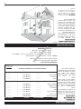
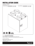
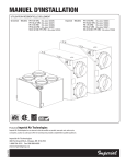
Installation Guide
gp
d.
su
n
w
ay
in
fo
.
co
m
.cn
Greentek Models SS 3.80 FSD HRV(Item No. 102208)
SS 3.80 FSD ERV (Item No. 102210)
Imperial Models SS 3.80 FSD HRV(Item No. 102257)
SS 3.80 FSD ERV (Item No. 102259)
Product of Imperial Air Technologies
Imperial Air technologies Inc. reserves the rights to modify a product, without prior notice,
whether in price, design, color or codes, in order to offer at all times quality products that are highly competitive.
Item# 102337
Imperial Air Technologies
480 Ferdinand Blvd., Dieppe, NB E1A 6V9
1-888-724-5211 Fax 506 388-4633
www.imperialgroup.ca
Page 2
gp
d.
in
ay
w
su
n
.cn
m
co
fo
.
important - Please read manual before installation
Caution: Do not install in a cooking area or connect directly to any appliance. Turn off all integral disconnects before servicing.
Notice: Prior to installing, serious consideration must be taken to insure this ventilation system will operate properly if integrated to any other type
of mechanical system, i.e. a forced air system, or an air handling unit. To insure proper operation & compatibilities of both system, it is required that the
airflow’s of the Heat Recovery Ventilator (HRV) or Energy Recovery Ventilator (ERV) be balanced, by following the procedures found in this manual.
Limitations: The product is for residential applications only. Must be installed in accordance with all national and local regulations, building and
safety codes.
to reduce or avoid the hazards of electric shock and fire:
cautions concerning the operation and full efficiency of this product:
• Use a dedicated AC 120V outlet only.
• Before servicing or cleaning the HRV system, always remove the
power cord from the AC wall outlet.
• Do not obstruct or cover the air intake or air outlet of the ventilation
system.
• To reduce the hazards of electric shock or fire, do not perform any
service to the HRV system other than those stated in the operating
manual instructions.
• Do not modify, repair or disassemble this system. These tasks are to
be performed by authorized serviced personnel only. Fire, electrical
shock and/or bodily injury may occur if these warnings are not
followed.
• To reduce the risk of electric shock, this ventilation system (HRV/ERV)
comes equipped with a 3-prong plug-in. This plug will fit in a polarized
outlet only one way.
• To prevent injuries, do not operate the ventilation system, while
servicing or maintaining. There are impeller wheels turning at a very
high speed that must fully stop rotating prior to accessing the inside of
the unit.
• Do not use ventilation system for outdoor application.
• Do not pull or twist power cord when disconnecting it from the
ventilation system. Grasp the plug firmly, not the cord.
• Always assess the operation of the ventilation system on how it may
interact with vented combustion equipment (ie. Gas Furnace, Oil
Furnace, Combustion, Appliances, etc.)
• Do not modify the power plug in any way; if modified, risk of electric
shock fire or even damage to the unit may occur.
• Do not use the ventilation system for removal of flammable fumes,
gases or connect directly to any appliances.
fo
.
co
m
.cn
• Do not use for swimming pool/spa applications.
ay
in
About Us
su
n
w
Imperial Air Technologies Inc. is the only manufacturer that offers you a complete range of products designed to improve indoor air quality, and that
provides a wide selection of accessories to facilitate installation.
d.
Our vision – To offer a complete range of products that satisfies environmental concerns.
gp
Whether your needs involve ventilation or filtration, we have the customized solution for you, with its range of quality products backed by the best
warranty in the industry.
Contents
section
Page
1. Performance & Specifications . . . . . . . . . . . . . . . . . . . . . . . 4
2. Ventilation requirements . . . . . . . . . . . . . . . . . . . . . . . . . . 5
3. Types of Installations . . . . . . . . . . . . . . . . . . . . . . . . . . .5-6
4. Installation Kit . . . . . . . . . . . . . . . . . . . . . . . . . . . . . . . . 7
5. Finding a suitable installation area for HRV or ERV . . . . . . . . . . 7
6. Installation of the HRV / ERV . . . . . . . . . . . . . . . . . . . . . . . . 7
7. Insulated Flex from Unit to Outside Wall . . . . . . . . . . . . . . . . . 8
8. Condensation Drain Line . . . . . . . . . . . . . . . . . . . . . . . . . . 8
9. Dedicated Electric Receptacle . . . . . . . . . . . . . . . . . . . . . . 8
10. Outside Fresh Air and Exhaust Air Hoods . . . . . . . . . . . . . . . 9
11. The matrix™ High Performance Ventilation Hood . . . . . . . . . . . 9
12. Benefits of the Duotrol™ System . . . . . . . . . . . . . . . . . . . . 10
13. Balancing the unit . . . . . . . . . . . . . . . . . . . . . . . . . . . 10-11
14. Controls Connection . . . . . . . . . . . . . . . . . . . . . . . . . 12-13
15. Wiring Diagrams for furnace interlock systems . . . . . . . . . . . 13
16. Troubleshooting . . . . . . . . . . . . . . . . . . . . . . . . . . . . . . 14
17. Maintenance . . . . . . . . . . . . . . . . . . . . . . . . . . . . . . . . 14
Page 3
1. Performance & Specifications
Ventilation Performance HRV SS 3.80 FSD
Net Supply
Air Flow
L/s
CFM
47
99
44
93
39
83
35
75
30
65
27
56
22
46
Gross Air Flow
Supply
L/s
CFM
48
100
45
94
40
84
35
75
30
66
27
57
22
47
Gross Air Flow
Exhaust
L/s
CFM
48
102
43
92
38
80
36
78
32
68
25
52
19
41
▲
Supply
■
Exhaust
in wg (Pa = n x 248.36)
External Static
Pressure
Pa
in. wg
25
0.1
50
0.2
75
0.3
100
0.4
125
0.5
150
0.6
175
0.7
cfm (L/s = n x 0.4719)
Ventilation Performance ERV SS 3.80 FSD
Net Supply
Air Flow
L/s
CFM
49
105
46
97
44
92
37
80
34
73
29
62
23
48
Gross Air Flow
Supply
L/s
CFM
49
105
47
99
44
93
38
81
35
74
29
63
23
49
Gross Air Flow
Exhaust
L/s
CFM
46
97
41
86
41
86
34
73
29
63
25
52
18
37
▲
Supply
■
Exhaust
in wg (Pa = n x 248.36)
External Static
Pressure
Pa
in. wg
25
0.1
50
0.2
75
0.3
100
0.4
125
0.5
150
0.6
175
0.7
.cn
cfm (L/s = n x 0.4719)
Energy Performance
ERV SS 3.80 FSD
Supply Net Power SensibleApparent
Temperature
Air Flow
Consumed
Recovery
Sensible
°C °F L/sCFM Watts
Efficiency Effectiveness
032 19 40 28
64
72
032 30 65 40
59
66
-25-13 18 37
30
55
73
Supply Net Power SensibleApparent
Temperature
Air Flow
Consumed
Recovery
Sensible
°C °F L/sCFM Watts
Efficiency Effectiveness
032 20 41
30
65
74
032 30 65 36
64
71
-155 16 35
27
54
80
This product earned the ENERGY STAR® by meeting strict energy
efficiency guidelines set by Natural Resources Canada and the US
EPA. It meets ENERGY STAR requirements only when used in Canada.
SPECIFICATIONS
HEATING
Total Recovery Efficiency
3595 19 41
43
COOLING
gp
d.
HEATING
su
n
w
ay
in
fo
.
co
m
Energy Performance
HRV SS 3.80 FSD
HRV SS 3.80 FSD
Size
20" x 14 ⁄2" x 18"
Weight
33.5 lbs (15.2 Kg)
CFM
30 to 100
Type of heat exchanger
cross-flow (Polypropylene)
Exchange surface
65 ft2
Voltage
120 VAC @ 60 Hz
Amperage
0.85 A
Defrost typeEvacuation
Certification CSA / HVI / Energy Star
Shipping Weight 41 lbs (18.6 Kg)
1
ERV SS 3.80 FSD
20" x 14 1 ⁄2" x 18"
32.5 lbs (14.7 Kg)
30 to 100
cross-flow (Enthalpy)
65 ft2
120 VAC @ 60 Hz
0.85 A
Evacuation
CSA / HVI
40 lbs (18.1 Kg)
Dimensions
5"
18"
2 51 ⁄64"
20"
Page 4
14 1 ⁄2"
2. Ventilation requirements
Determine Your
Ventilation Needs
installation
A. Room Count Calculation
LIVING SPACENumber of Rooms
Master Bedroom
How much fresh air do I need?
Good air quality is based in part
on the capacity of the home’s
ventilation system.
With Basement
Usually, the HRV’s/ERV’s capacity
is measured in CFM (Cubic Feet
per Minutes) or L/s (Liters per
Seconds) of fresh air being
distributed in the living space.
The Room Count Calculation or
the Air Change per Hour Method
shows you how to determine your
ventilation needs.(see chart on
right)
Dinning Room
Single Bedroom Living Room
Family Room
Recreation Room
Other
Kitchen
Bathroom
Laundry Room
Utility Room
CFM (L/s)
CFM Required
————
————
x 20 cfm (10 L/s)
= ————
x 20 cfm (10 L/s)
= ————
————
————
x 10 cfm (5 L/s)
= ————
x 10 cfm (5 L/s)
= ————
————
————
x 10 cfm (5 L/s)
= ————
x 10 cfm (5 L/s)
= ————
————
————
x 10 cfm (5 L/s)
= ————
x 10 cfm (5 L/s)
= ————
————
————
x 10 cfm (5 L/s)
= ————
x 10 cfm (5 L/s)
= ————
————
————
x 10 cfm (5 L/s)
= ————
x 10 cfm (5 L/s)
= ————
TOTAL ventilation requirement (add last column)
=
————
1 CFM = 0.47189 L/s
1 L/s = 3.6 m3/hr
m
d.
su
n
w
ay
in
fo
.
A 25’x 40’ house with basement
1,000 Sq. ft. x 8’ high x 2(1st floor + basement) = 16,000 cu. ft.
16,000 cu. ft. x 0.35 ACH = 5,600 cu. ft.
5,600 cu. ft. / 60 Minutes = 93.3 CFM
93.3 CFM is your ventilation need
gp
Example:
co
TOTAL cu ft X 0.35 per hr = total
Take total and divide by 60 to get CFM
.cn
B. Air Change per Hour Method
3. Types of Installations
Independent System
installation
figure 3.1
This application uses a devoted
duct system for the supply
and the exhausting of stale air
accumulated in the home.
It is recommended to install fresh
air grilles in all bedrooms and living
areas. Exhaust the stale air from
the bathroom, kitchen and laundry
room. (see figure 3.1)
Important: For optimal performance
of your HRV or ERV, the installation of an
optional 6” round galvanized backdraft
damper is required on the fresh air to
home duct work.
Page 5
3. Types of Installations (continued)
Exhaust at the
source and supply in
the return
figure 3.2
This application uses a devoted
duct system for the exhausting of
stale air accumulated in the home.
The fresh air is dumped into the
return air duct and is distributed
thru the home by the existing
supply air ductwork of the forced
air system. (see figure 3.2)
From Bathroom
or Kitchen
To living space
Minimum
10' (3 m)
6'
(1.83 m)
Make sure when using this
application that your fresh air duct
connection to the forced air system
return air duct is at a minimum
of 10ft (3 m) from the forced air
system. You should check with
your local code or the forced air
system’s manufacturer.
18" (457 mm)
HRV / ERV
Forced Air System
The forced air system’s blower
does not essentially have to run
when the unit is in continuous
mode, but recommended for
maximum efficiency.
*For minimum distance between return and forced
air system, check with your local building codes and
forced air system manufacturer.
CAUTION: Insure the unit runs in conjunction
with forced air system (Ref section 14)
Supply air from HRV/ERV must be
at least a minimum of 10ft (3 m)
from the forced air system. Can be
different from a region to an other.
You should check with your local
code or the forced air system’s
manufacturer.
w
su
n
6'
(1.83 m)
To living space
Forced Air System
HRV / ERV
*For minimum distance between return and forced
air system, check with your local building codes and
forced air system manufacturer.
Important: Building and combustion appliance
installation codes do not allow return air grilles or
openings such as "breather tee" or indirect connections
in an enclosed room that is susceptible to spillage of
combustion appliances.
Simplified Connection
Indirect Connection
2"
(51 cm)
Page 6
Minimum
10' (3 m)
18" (457 mm)
CAUTION: The HRV and forced
air system must be in continuous
mode, to achieve maximum comfort
and to avoid cross-contamination.
Important: For optimal performance
of your HRV or ERV, the installation of an
optional 6" round galvanized backdraft
damper is required on the fresh air to
home duct work.
6'
(1.83 m)
d.
When using this application make
sure that there is minimum 6 feet
between the fresh air and exhaust
air connections of the HRV/ERV in
the return air duct. (see figure 3.3)
figure 3.3
gp
Exhaust and supply
in the return
ay
in
fo
.
co
m
.cn
Note to installer: Dwellings
with multiple forced air systems
requires one HRV/ERV per system.
Breather Tee
4. Installation Kit
Included in the
installation kit:
figure 4.1
• 4 Collars
• 4 Caps, Pressure Taps (9753K74)
• 1 Condensation Drain Line
• 1 Drain Adapter with Nut
• 12 screws (#10 x 11/4”)
• 2 screws (#8 x 3/8”)
• AC 120V power cord
• Wall Mounting Bracket
5. Finding a suitable installation area for HRV or ERV
The HRV/ERV unit should be installed in a mechanical room or as close to an outside wall as possible. This
would assure a short run of insulated flexible duct.
.cn
The HRV/ERV unit must always be installed in an area where the air is tempered to avoid freezing of the
condensate line. The contractor should install the unit in an area that is very accessible to allow the homeowner
easy access for maintenance.
in
fo
.
co
m
It is very important to install an electric receptacle (115v) near the HRV / ERV, a separate circuit breaker is
also recommended. You should have access to a condensate drain near the HRV/ERV to avoid the use of
condensate pump.
w
su
n
d.
A) Minimum two 2"x 4" (50.8 mm
x 101.6 mm) wood wall studs
and minimum 3⁄8 " (9.5 mm) thick
drywall is required to secure
the HRV/ERV wall bracket.
gp
IMPORTANT Minimum installation
requirements
ay
6. Installation of the HRV / ERV
B) Support for weight of 80 lbs,
which includes HRV/ERV, duct
connections and accessories.
Proper installation requires that
the unit be secure to the wall. If
there is no wall studs available,
please secure a 3 ⁄4" plywood
to wall studs then fasten wall
mounting bracket to plywood.
figure 6.1 Installation of the wall bracket. Secure with two #10 x 11⁄4" screws.
tip to installer: If the unit is not
level, improper drainage will occur
and could lead to moisture and
leakage problems.
It is recommended to use
approximately 16 inches of flexible
duct between the HRV/ERV and
your rigid duct. The flex duct is
mounted the same way to the HRV/
ERV as the insulated flex.
figure 6.2 Hang HRV/ERV to wall mounting
bracket.
figure 6.3 When completing the procedure
make sure that the HRV/ERV is leveled.
figure 6.4 Proceed to secure HRV/ERV to
bracket with the two #8 x 3⁄8 " screws.
Page 7
7. Insulated Flex from Unit to Outside Wall
tip to installer: To ensure a
better installation and to avoid an
undesired bend in the duct, align
the duct with the collar before
securing over the four hooks.
Warning: Always fix and secure
the 5" collars with the screws supplied.
Avoiding this critical step the unit will
figure 7.1 Insert vinyl duct over the hooks
accumulate condensation.
and seal with a Tie wrap.
figure 7.2 Insert insulation inside the collar.
figure 7.3 Finish by taping the duct on the
collar.
m
.cn
Once insulated flex is attached to the collar, slide collar in keeper section, fixed collar to the unit with four
screws supplied in installation kit.
Figure 7.5 Fix and secure the collars to the HRV/
ERV with the #10 x 11⁄4" screws, supplied in kit.
in
fo
.
co
figure 7.4 Slide collar on the unit.
su
n
w
ay
8. Condensation Drain Line
gp
d.
Insert the threaded drain adapter
thru the bottom of the HRV/ERV and
hand tighten the plastic nut, and with
a wrench tighten the nut another half
turn to assure a better seal.
Install the condensate line
(included in drain kit). Insert
condensate tubing by pushing
clear plastic line over drain
adapter. Make condensate trap
by looping the clear plastic tubing.
This procedure is to avoid foul odor
to enter the HRV or ERV.
figure 8.1 Make a loop in condensate line, not be subject to
freezing temperatures.
9. Dedicated Electric Receptacle
IMPORTANT: Always consult
a certified technician to insure
proper installation of main power.
Note: If LED light on the Duotrol
remains green, motors not
energized controls do not operate.
Polarization in main AC outlet are
inverted.
It is recommended that the HRV/
ERV have a dedicated receptacle
with 115v. It is not recommended to
connect unit with an extension cord.
Page 8
figure 9.1 Insert the power cord on top of the unit. Press firmly to
make sure the power cord is secure.
figure 8.2 Use a condensate pump if you don’t have access to a drain.
10. Outside Fresh Air and Exhaust Air Hoods
tip to installer: We recommend
and it is good practice to have a
minimum of 6ft (1.83 m) between
the supply and exhaust vents,
unless using a concentric vent
design to prevent contamination of
intake air.
6ft (1.83 m)
Note: Outdoor air intake hoods shall
be located to avoid contamination
from sources such as:
• Exhaust air openings
• Driveways (auto exhaust)
18" (457 mm)
• Combustion appliances
• Gas meters, oil fill pipes
• Garbage containers
• Attics or crawl spaces
• Under deck or other areas of
questionable air quality
figure 10.1 Locating Outside Hoods
Important: Always consult your national and
local regulations, building and safety codes.
Airflow &
Installation
m
.cn
11. The matrix™ High Performance Ventilation Hood
Exhaust air from home
“TOP”
fo
.
co
Exterior wall
w
ay
in
IMPORTANT: Install ventilation hood
a minimum of 18” (457mm) above grade.
Fresh air to home
“BOTTOM”
gp
d.
su
n
Do not install under a deck, enclose
porch, patio, garages, crawl spaces or
attics.
WARNING: Insure the ventilation
hood is at a minimum clearance of 6 ft
(1.83 m) away from the exhaust vents of
a combustion source and contaminants.
Exhaust air
to outside
Ex: Gas furnace, dryer, gas boilers,
range hoods, barbecue, garbage bin,
driveway or garage.
Ventilation
cap
Uniquely design individual
insulated transition duct (UL 94 Rated)
Transition
connector plate
Important: Always consult national and your
local regulations, building and safety codes.
Limitation: This product is for residential
applications only.
Fresh air from outside
Airflow Performance Data
Supply Air Flow Performance
0.25
External Static Pressure
in wg (Pa = n x 248.36)
Limitations: This product is for
residential applications only. Must be
installed in accordance with all current
national and local regulation building
and safety codes.
Exhaust Air Flow Performance
0.25
External Static Pressure
in wg (Pa = n x 248.36)
Airflow
Performance Data
0.2
0.15
0.1
0.05
0
30
45
60
75
90
CFM (L/s = n x 0.4719)
105
120
0.2
0.15
0.1
0.05
0
30
45
60
75
90
105
120
CFM (L/s = n x 0.4719)
Limitations: This product is for residential applications only. Must be installed in accordance with all current national and local regulation building and safetyPage
codes.
9
12. Benefits of the Duotrol™ System
Mode Selector
Acts as a mode selector
• Intermittent
Intermittent: When the selector switch is in the intermittent position
the HRV/ERV will only run when there is a call for ventilation by any
control. At that time the unit will run on high speed until the condition
is satisfied.
• Continuous
• Off
Continuous: When the selector switch is in the continuous position
the HRV/ERV will run continuously on pre set speed except when there
is a call for override by any control.
Off: When the selector switch is in the off position the HRV/ERV will not
come on even if there’s a call for ventilation by any control.
Speed Adjustment
+ Button: Increase the speed of the selected motor.
• Increase Speed ( + )
– Button: Decrease the speed of the selected motor.
• Decrease Speed ( – )
m
co
Using the Selector Switch
fo
.
tip to installer: When on Balancing Mode, the
Selector Switch allows you to choose the motor you
want to set.
2. CONT (Both Motors)
d.
1. INTER (Exhaust Motor)
su
n
A) Closed Duotrol Cover
gp
GREEN LIGHT
Mode Selector
w
ay
in
with the Duotrol™
System
.cn
13. Balancing the unit
3. OFF (Supply Motor)
Page 10
Duotroltm Balancing system
YELLOW LIGHT
Balancing Mode Procedures, Steps 1 through 8.
B) Open Duotrol Cover
1. UP (Exhaust Motor)
2. MIDDLE (Both Motors)
3. DOWN (Supply Motor)
Step 1: Press the (+) and (–) buttons simultaneously
until you see the yellow light. Once the indicator light
turns yellow you are in balancing mode.
Step 5: Then perform the same operation on the stale
air side by selecting the «INTER» position on the
DuotrolTM.
Step 2: When in balancing mode the selector switch
becomes the motor selector switch. INTER (Right
Motor), CONT (Both Motors) and OFF (Left Motor)
Step 6: The «CONT» position will allow you to
adjust the cfm on both motors proportionately (if
necessary).
Step 3: Once the total cfm needed is determined,
you can start balancing the HRV/ERV. Set your fresh
air supply by selecting the «OFF» position on the
Duotrol TM. Install your magnehelic gauge and air flow
grid in the fresh air duct.
Step 7: Once this is completed, you have set the high
speed on your HRV/ERV. To lock balancing mode you
must press (+) and (–) buttons simultaneously and
release. The indicator light will turn green to indicate
normal operation mode.
Step 4: Press the (–) button to decrease the cfm or
press the (+) button to increase the cfm.
Step 8: Once high speed is set and locked, switch
to continuous on the Duotrol TM. By using (+) and (-)
buttons set low speed on the HRV/ERV.
13 Balancing the unit (continued)
with the Duotrol
system and
the integrated
balancing taps and
Magnehelic gauge.
HIGH (Exhaust Air to Outside)
LOW (Exhaust Air from Home)
Magnehelic gauge
Balancing Tap Connection*
Magnehelic gauge
HIGH (Fresh Air to home)
LOW (Fresh Air from Outside)
Connecting the Magnehelic gauge to the collar balacing taps, then proceed to section 13 (on page 10) Duotrol tm
Balancing System Procedures and follow the Steps 1 through Step 8.
ay
w
su
n
d.
gp
Note: To perform a proper install,
the External Static Pressure (ESP)
needs to be measured at each
of the 4 stations. Then proceed
to measure the Delta P(DP) to
determine the corresponding
airflow (e.g. 50 CFM), then do the
iteration until the unit is balanced
both the (ESP and airflows).
Fresh Air
L/s
44
41
39
37
35
33
30
29
26
24
22
19
17
m
co
Pressure
Pa
in. wg
50
0.20
62
0.25
75
0.30
87
0.35
100
0.40
112
0.45
125
0.50
137
0.55
150
0.60
162
0.65
175
0.70
187
0.75
199
0.80
.cn
Balancing Chart when using collar pressure taps.
in
The balancing chart is based on a
Delta P (DP) measurement (also
located on the access panel of the
ventilation system)
fo
.
balancing chart
CFM
93
87
83
79
74
69
65
61
56
50
46
41
36
Exhaust Air
L/s
CFM
43
90
40
85
37
79
36
77
36
76
34
71
32
67
28
60
24
51
22
47
19
41
17
36
15
31
*Important: Once balancing is complete, insure all four pressure taps are sealed with the rubber caps. Pressure taps
(9753K74) supplied in the installation kit.
with an airflow grid
& Magnehelic Gauge
Magnehelic Gauge with Air Flow Grid
Inserting Air flow grid in duct
Seal Air flow grid in duct with duct tape.
Page 11
14. CONTROLS CONNECTION
RD-1 (2 wires)
G
G
R
G
R
B
G
W
B
W
R
R
RD-2, RD-3P, RD-4P (4 wires)
.cn
R
R
G
G
B
B
W
W
B G R
B G R
Vectouch (4 wires)
m
Jumper
Jumper
JP-4*
JP-4*
in
ay
w
su
n
2 Relays
2 Relays
d.
* Jumper JP-4 "ON" offers (Intermittent
and Continuous modes) P, RNC, SS3.12
FSD, SS3.80 FSD and the LCH Series.
* Jumper JP-4 "OFF" offers (Intermittent,
Recirculation and Continuous modes)
model DH and the SS3.12DD Series only.
LVC Version 1
LVC Version 1
fo
.
co
NOTE: With LVC version 1 it is normal
that the wall control LCD panels doesn't
turn off when the Duotrol on the unit is in
the "OFF" position.
gp
RB
G
BW
G BR
RG
RW B G
To Casing
Screw
ToGround
Casing
for
Screw
for Ground
Jumper
Jumper
JP-4*
JP-4*
Jumper
Jumper
JP-4*
JP-4*
LVC
LVC Version
Version 1
1
LVC Version 2
LVC Version 2
2
2 Relays
Relays
R
RW
W B
B G
G
To
To Casing
Casing
Screw
Screw
for Ground
Ground
for
1 Relay
1 Relay
RW B G
RW B G
Jumper
Jumper
JP-4*
JP-4*
LVC
LVC Version
Version 2
2
CAUTION: Minimum wire requirements is LVT18 CSA/UL 4 strain to insure proper connection.
Page 12
1
1 Relay
Relay
14. CONTROLS CONNECTION (continued)
T3 Timer (3 wires)
B G R
15. Wiring Diagrams for furnace interlock
Jumpersystems
24 VAC
5 VDC
2 Relays
m
.cn
RW B G
co
5 VDC
Low Voltage HRV Controller
Force Air System
ay
in
A relay is normally used when tying
a ventilation system to the forced air
distribution system. Our Duotrol System
is equipped with an internal relay that
will activate the forced air system’
ventilator when there is a demand from
the HRV /ERV. The Duotrol System will
activate the INTERLOCK relay during
the following modes: Continuous,
To Casing
Screw
Override,Recirculation and Defrost.
for Ground
See wiring diagram.
LVC Version 1
JP-4*
fo
.
Standard Forced Air
Interlocking Wiring
w
Legend: -------- Field Installed Low Voltage
su
n
Figure 15.1 Standard forced air wiring diagram
Some forced air system thermostat
will activate the cooling system when
tied using the «Standard forced air
interlocking wiring».
If you have identify this type of
thermostat you must proceed with the
«Alternate Forced Air Wiring».
Jumper
JP-4*
d.
gp
Alternate Forced Air
Interlocking Wiring
24 VAC
LVC Version 2
5 VDC
1 Relay
RW B G
5 VDC
Locating the
Wiring Diagram
Note to installer: Wiring
Diagram for the entire line of HRV/ERV
Models are placed on the back of each
Exhaust motor bracket.
CAUTION: Thermostat that control
A/C system must use the Alternate
Interlock Wiring Diagram.
Force Air System
Low Voltage HRV Controller
*Before tying the HRV/ERV to
a forced air system, always
refer to system’s manual or
manufacturer.
Thermostat
Legend: -------- Field Installed Low Voltage
Figure 15.2 Alternate forced air wiring diagram
Warning: Always disconnect the unit prior to making any connections. Failure to disconnecting the power could result in electrical shock or can damage the electronic boards, wall controls and/or unit.
CAUTION: Minimum wire requirements is LVT18 CSA/UL 4 strain to insure proper connection.
Page 13
16. Troubleshooting
Need help? You benefit from certified
customer service ready to guide you
in the installation or operation of your
system.
Call Toll free: 1 888 724-5211
PROBLEMSSOLUTIONS
• HRV/ERV not running
• Verify polorization
• Verify breaker in electrical box
• Verify that dehumidistat or switch on HRV/ERV are activated to supply power to unit.
• Unplug HRV/ERV verify if controller is wired correctly to the connection box on the side of the unit.
• Verify low voltage box (Duotrol TM )on the unit
Accessories
• Air is too dry
• Increase humidity level on dehumidistat.
Using the appropriate accessories, your
system will be simple to install and its
performance will be optimal.
• Switch ventilation mode from continuous to intermittent
• Install a humidifier
•Air too humid
• Reduce the humidity level on the controller.
• Verify if dryer is venting in basement.
• Verify if heating wood is stored in basement.
Choose from the complete range of
ventilation accessories and products by
“Imperial Air Technologies Inc”.
• Wait for outside temperature to change.
Ex. Summer can be extremely humid.
• Verify balancing of the HRV or ERV.
.cn
ay
in
fo
.
co
m
17. Maintenance
su
n
d.
gp
When should I Service my
HRV/ERV?
w
Warning:
ALWAYS UNPLUG HRV/ERV DURING
SERVICING
HEAT RECOVERY &
Energy recovery CORE UNIT
Once a year or as needed, vacuum the
four surfaces, let soak in warm water for
15 minutes, then spray rinse and let dry.
figure 17.1 Slide Out the Filters
FILTERS
Four times a year or as needed, vacuum
the filters. Replace filters once a year.
INSIDE THE UNIT
Once a year or as needed, vacuum all
surfaces inside the unit.
figure 17.3 Slide out the Core
Page 14
figure 17.2 Vacuum the Filters
gp
d.
in
ay
w
su
n
.cn
m
co
fo
.
NOTES
Page 15
.cn
m
co
fo
.
in
ay
w
su
n
d.
gp
Item# 102337
Imperial Air Technologies
480 Ferdinand Blvd., Dieppe, NB E1A 6V9
1-888-724-5211 Fax 506 388-4633
www.imperialgroup.ca
gp
d.
in
ay
w
su
n
.cn
m
co
fo
.
Item# 102337
Imperial Air Technologies
480 Ferdinand Blvd., Dieppe, NB E1A 6V9
1-888-724-5211 Fax 506 388-4633
www.imperialgroup.ca
gp
d.
in
ay
w
su
n
.cn
m
co
fo
.
Page 15
NOTES
16. Dépannage
Besoin d'aide? Bénéficiez d'un service
à la clientèle assuré par du personnel
certifié et prêt à vous guider dans
l'installation ou l'utilisation de votre
système Greentek MD.
Sans frais: 1 888 724-5211
Accessoires
Avec les accessoires appropriés,
l'installation de votre système se fera
en toute simplicité et en améliorera son
rendement.
Choisissez parmi la gamme complète
d'accessoires et de produits de
ventilation « Imperial Air Technologies
Inc ».
PROBLÈMESSOLUTIONS
• VRC/VRE ne fonctionne pas
• Vérifier le disjoncteur dans le panneau électrique
• Vérifier que l’interrupteur du déshumidistat et de la boite de contrôle sur le
VRC/VRE sont en position apport de courant à l’unité.
• Réduiser le niveau d’humidité sur le module de contrôle
• L’air est trop humide
• Installer un humidificateur
• Changer le mode de ventilation du mode continu à intermittent
• Augmenter le niveau d’humidité sur le déshumidistat
• L’air est trop sec
• Vérifier l’ampérage des moteurs
• Vérifier si le courant atteint la boîte de connexions (bas voltage)
• Vérifier si le courant atteint le transformeur
• Débrancher le VRC/VRE et vérifier si le module de contrôle est bien branché
à la boîte de connexions sur le côté de l’unité
• Vérifier si du bois de chauffage est entreposé dans le sous-sol
• Vérifier si la sécheuse évacue dans le sous-sol
• Attendre que la température extérieure change
(ex. En été, la température peut être extrêmement humide)
• Vérifier le balancement du VRC/VRE
gp
d.
in
ay
w
su
n
17. Maintenance
fo
.
.cn
m
co
AVERTISSEMENT:
TOUJOURS DÉBRANCHER TOUT
APPAREIL ÉLECTRIQUE AVANT
L’ENTRETIEN.
Quand devrais-je entretenir
mon VRC/VRE
ÉCHANGEUR THERMIQUE
Une fois par année ou au besoin,
nettoyer les quatre surfaces avec l'aide
d'un aspirateur et laisser tremper dans
de l'eau tiède savonneuse pour environ
trois heures, rinser et laisser sécher.
figure 17.1 Enlever les filtres
figure 17.2 Nettoyer à l’aide d’un aspirateur
FILTreS
Quatre fois par année ou au besoin,
nettoyer les filtres avec l'aide d'un
aspirateur. Remplacer les filtres une fois
par année.
INTÉRIEUR DE L’UNITÉ
Une fois par année ou au besoin,
nettoyer l'intérieur de l'appareil
figure 17.3 Glisser l’échangeur thermique vers l’extérieur
Page 14
14. Contrôles et branchement (suite)
Minuterie T3 (3 fils)
B G R
15. Diagramme de raccordement avec système
Jumpeur à air forcé
LVC Version 1
JP-4*
Raccord standard avec un
système à air forcé
24 VAC
5 VDC
gp
Un relais est normalement utilisé pour
raccorder un système de ventilation
à un système à air forcé. Notre
2 Relais
système DuotrolMD est doté d’un relais
intégral qui permet de commander le
RW B G
démarrage du ventilateur du système
à air forcé lors d’une demande
provenant du VRC/VRE. Le système
DuotrolMD du VRC/VRE active
Viserlea
une vis
relais INTERLOCK pendant les modes
cabinet
d’opérations suivants : ducontinu,
pour la
Contrôle à voltage bas de VRC/VRE
demande, recirculation et dégivrage.
prise
de terre.
Voir diagramme de branchement
ciLégende : -------- Ligne installée à voltage bas
contre.
d.
ay
w
su
n
5 VDC
in
Système à air forcé
co
fo
.
.cn
m
Figure 15.1 Raccord standard avec un système à air forcé
Raccord auxiliaire avec un
système à air forcé
Certains thermostats du système à air
forcé branché avec le raccord standard
ci-dessus vont activer le système de
climatisation. Lorsque vous identifiez
ce type de thermostat, veuiller procéder
avec l’installation à raccord auxiliaire
avec un système à air forcé.
Jumpeur
JP-4*
LVC Version 2
24 VAC
5 VDC
1 Relai
RW B G
Localiser l’emplacement du
diagramme de branchement
Note à l’installateur : Le
diagramme de branchement pour tous
les modèles Professionnel, De Luxe ,
séries SS3,12 et SS3,80 sont localisés
à l’intérieur du bras de support sur le
moteur d’évacuation.
5 VDC
Système à air forcé
Contrôle à voltage bas de VRC/VRE
*Toujours ce référer aux
spécifications du manufacturier
avant de raccorder un VRC/VRE
à un système à air forcé..
Thermostat
Legend: -------- Ligne installée à voltage bas
Figure 15.2 Raccord auxiliaire avec un système à air forcé
avertissement: Avant d'effectuer tous raccordements, toujours débrancher l'appareil, sans débrancher pourrait créer les risques de choc
électrique, endommager les plaques électronique, les contôles mural ou l'appareil.
Page 13
14. Contrôles et branchement
RD-1 (2 fils)
G
G
R
R
G
G
B
B
W
W
R
R
RD-2, RD-3P, RD-4P (4 fils)
R
R
G
G
B
B
W
W
B G R
B G R
gp
d.
Vectouch (4 fils)
su
n
Jumpeur
Jumpeur
JP-4*
JP-4*
LVC Version 1
LVC Version 1
in
ay
w
NOTE: Avec la version 1 du LVC, il
est normal que le paneau LCD est pas
éteint, lorsque le Duotrol sur l'appareil
est en position "OFF".
co
fo
.
2 Relais
2 Relais
.cn
m
* Jumpeur JP-4 "ON" offre les modes
(Intermittent et continue) conçu pour
les modèles P, RNC, SS3,12 FSD, SS3,80
FSD et la Série LCH.
* Jumpeur JP-4 "OFF" offre les modes
(Intermittent, recirculation et ventilation
continue) conçu pour les modèles DH et
SS3,12 DD seulement.
G
RG
BW
G BR
RB
RW B G
Viser a
Viser
a
une vis
une vis
du cabinet
du cabinet
pour la
pour
la
prise
de prise
terre.
de terre.
Jumpeur
Jumpeur
LVC Version
Version 1
1
LVC
JP-4*
JP-4*
Jumpeur
Jumpeur
JP-4*
LVC Version 2
JP-4*
LVC Version 2
2 Relais
Relais
2
RW
W B
B G
G
R
Viser aa
Viser
une vis
une
vis
du cabinet
cabinet
du
pour
pour la
la
prise
prise
de
de terre.
terre.
1 Relai
1 Relai
RW B G
RW B G
Jumpeur
Jumpeur
JP-4*
JP-4*
LVC
LVC Version
Version 2
2
avis: Un fil minimum de LVT18 CSA/UL à 4 brins est requi pour le raccordement.
Page 12
1 Relai
Relai
1
13 Balancement de l’appareil (suite)
LE SYSTÈME DE
BALANCEMENT
DUOTROL AVEC PRISES
DE PRESSION INTÉGRER
DE COLLETS
HIGH (Évacuation d'air vicié)
LOW (Aspiration d'air vicié)
Cadran Magnehelic
Prise de pression*
Cadran Magnehelic
HIGH (Distribution d'air frais)
LOW (Aspiration d'air frais)
En reliant le cadran Magnehelic aux prises de pression des collets, procédez alors à la section 13 utilisation du
Duotrol en mode de balancement (page 10) Duotrol et suivent les étapes 1 à l'étape 8.
Tableau de valeurs pour l’équilibrage du VRC/VRE
gp
TABLEAU DE VALEURS
Air frais
L/s
44
41
39
37
35
33
30
29
26
24
22
19
17
in
ay
w
su
n
Pression
Pa
po d'eau
50
0.20
62
0.25
75
0.30
87
0.35
100
0.40
112
0.45
125
0.50
137
0.55
150
0.60
162
0.65
175
0.70
187
0.75
199
0.80
d.
Le tableau de valeurs d’équilibrage
est basé sur une measure de Delta
P (DP) aussi situé sur la panneau
d’accès du VRC/VRE.
.cn
m
co
fo
.
Note:
Pour
exécuter
un
balancement approprié, la pression
statique externe, doit être mesuré
à chacun des 4 stations. Procèdez
alors pour mesurer le Delta P (DP)
pour determinez la correspondence
des debits d’air, (example 50 PCM)
faite alors l’itération jusqu’à ce que
le VRC/VRE soit équilibré.(Pression
Statique Externe et Débit d’Air)
PCM
93
87
83
79
74
69
65
61
56
50
46
41
36
Air vicié
L/s
43
40
37
36
36
34
32
28
24
22
19
17
15
PCM
90
85
79
77
76
71
67
60
51
47
41
36
31
*Important : Une fois que l'équilibrage est completé, sceller l'extrémité des prises de pressions à l'aide des capuchons
en caouchouc (No. 9753K74), fournis dans la trousse d'installation.
AVEC CADRAN
MAGNEHELIC ET
GRILLE DE LECTURE
DE DÉBIT D’AIR.
Cadran magnehelic avec grille de lecture
de débit d’air.
Insérer la grille dans le conduit.
Sceller la grille avec du ruban adhésif à
conduits.
Page 11
12. Bénéfices du système de balancement Duotrol™
Intermittent : Le VRC/VRE s’activera seulement lorsqu’il y aura une
demande de ventilation.
• Intermittent
Agit de sélecteur de mode
Selecteur de modes
• Continu
• Arrêt
Continu : Le VRC/VRE fonctionne continuellement en basse vitesse,
excepté lorsqu’il y a une demande de ventilation ou l’unité changera à
haute vitesse.
arrêt : La fonction «off» empêche le VRC/VRE de s’activer lors d’une
demande de ventilation.
Contôle de
balancement
+ Sélecteur : Augmente la vitesse.
– Sélecteur : Diminue la vitesse.
• Augmentation de vitesse ( + )
• Diminution de vitesse ( – )
gp
d.
13. Balancement de l’appareil
su
n
Utilisation du Duotrol en mode
de balancement
ay
w
with the Duotrol™
System
Conseils Imperial à l’installateur: Le bouton
glissoir vous permet de sélectionner le moteur désiré.
in
co
fo
.
2. MILIEU (les deux moteurs simultanément)
2. CONT (les deux moteurs simultanément)
1. HAUT (moteur d’évacuation)
1. INTER (moteur d’évacuation)
B) Porte ouverte
A) Porte fermée
.cn
m
LUMIÈRE VERTE
Sélecteur de mode
Étape 5 : Ensuite, en sélectionnant le moteur de
droite, répéter les mêmes étapes pour votre débit
d’air vicié.
Étape 1 : Appuyer simultanément sur les boutons +
et – pendant 5 secondes. Une fois que l’indicateur
lumineux devient jaune, vous êtes en mode de
balancement.
3. BAS (moteur d’alimentation)
3. OFF (moteur d’alimentation)
Procèdures mode de
LUMIÈRE JAUNE
Mode de balancement balancement étapes 1 à 8.
Étape 2 : En mode de balancement, l’interrupteur
de sélection devient le sélecteur de moteur (droit,
ensemble ou gauche)
Étape 3 : Vous pouvez débuter le balancement
des moteurs une fois que les débits de PCM sont
déterminés. Sélectionner le débit d’air frais à l’aide
du sélecteur de moteur gauche sur le système
DuotrolMD.
Étape 6 : En appuyant simultanément sur les boutons,
vous sécuriser le débit. Vous ne pouvez changer le
débit qu’en recommençant les étapes 1 et 2.
Étape 7 : Les étapes 1 à 6 vous permettent de régler le
mode haute vitesse de votre VRC/VRE.
Étape 8 : Maintenant, vous pouvez ajuster le mode
basse vitesse en appuyant sur les boutons (+) et (-).
Étape 4 : En appuyant sur le bouton (-) vous allez
diminuer le montant de PCM et en appuyant sur le
bouton (+), vous allez augmenter le montant de PCM.
Page 10
10. Installation des évent extérieurs
Conseils à l’installateur :
Nous recommandons un minimum
de 6 pi (1.83 m) entre les évents
d’air frais et de l’air vicié. À moins
d’utilisé un évent concentrique
conçu
pour
empêcher
la
contamination d'air .
6 pi (1.83 m)
Note: Les évents extérieurs d'air
frais doivent êtres localisés pour
éviter la contamination à partir des
sources comme :
• Ouvertures d’air vicié
18 po (457 mm)
• Entrée, Garage
(Échappement de véhicule)
• Échappement d’appareils de
combustion
• Compteurs à gaz, pipes de pétrole
• Contenant d'ordures
• Greniers ou sous-sol
• Sous une plate-forme ou d'autres secteurs où la qualité de l'air est en
question.
figure 10.1 Localiser l’emplacement des évents sur la maison.
Important : Veuillez vérifier auprès des codes
de construction national et locaux.
gp
11. The matrix™ Évent de ventilation haute performance
d.
Mur extérieur
su
n
Évacuation de l’air vicié
vers l’extérieur.
ay
w
Circulation d’air et
installation
in
IMPORTANT: Installez évent de
ventilation à un minimum de 18 po
(457mm) du sol.
co
fo
.
Air frais distribué
vers l’intérieur
.cn
m
Ne pas l’installer sous une terrasse,
ni dans un porche fermé, un
garage, grenier ou toutes espaces
non-conditionnés.
AVERTISSEMENT : S’assurez que
l’évent de ventilation matrix tm est à une
distance minimale de 6 pi (1,83 m) des
conduits d’évacuation de toute source
de combustion ou de contaminants : Ex
: Fournaise au gaz, sécheuse, chauffaux
au gaz, barbecue, compteur de gaz,
hôtte de cuisine, poubelle, allée ou
garage.
Air vicié
évacué à
l’extérieur
Conduit simple de transition isolé.
(R4.0 / classé UL 94)
Plaque
de transition
Capuchon de
ventilation
Important : Veuillez vérifier auprès des codes
de construction national et locaux.
Air frais provenant de l’extérieur
Rendement de ventilation
rendement de
ventilation
Limitations: Ce produit est conçu
pour des applications résidentielles
seulement. Il doit être installé
confomément de tout code national et
local du bâtiment en vigueur.
Évacuation
Alimentation
0.25
Pression statique externe
wg (Pa = n x 248.36)
0.25
Pression statique externe
wg (Pa = n x 248.36)
0.2
0.15
0.1
0.05
0
30
45
60
75
90
105
0.2
0.15
0.1
0.05
0
120
30
45
60
75
90
105
120
PCM (L/s = n x 0.4719)
PCM (L/s = n x 0.4719)
LIMITATIONS : Ce produit est conçu pour des applications résidentielles seulement. Il doit être installé confomément de tout code national et local du bâtiment en vigueur.
Page 9
7. Conduit flexible isolés
Conseils à l’installateur:
Pour assurer une installation
optimale et pour ne pas nuire à la
trajectoire du conduit flexible, nous
vous recommandons d’aligner le
conduit à l’unité avant de l’installer
par-dessus les quatres agraffes de
fixation.
AVERTISSEMENT: Toujours utiliser figure 7.1 Insérer le conduit en vinyl pardessus les quatres agraffes de fixation.
les écrous fournient dans la trousse
d’installation afin de fixer le système
de collet. Ceci pour assurer un
fonctionnement optimal du système de
ventilation et éliminer les chances de
condensation du cabinet du système de
ventilation.
figure 7.2 Insérer la gaine isolante à
l’intérieur de la double paroie du collet
amovible.
figure 7.3 Terminer par sceller le coupe
vapeur au collet avec du ruban.
gp
d.
su
n
Figure 7.5 Attacher les collets avec l’aide
d’écrous (#10 x 1 1⁄4 po de longueur).
in
ay
w
figure 7.4 Glisser le collet à l’appareil.
co
fo
.
8. Drain et conduit de condensation
.cn
m
Une longueur de tuyau de drain de
10 pi est fournie avec l’unité. Installer
tout d’abord l’adapteur de drain dans
le trou au fond de l’appareil puis fixer
en utilisant l’écrou. Serrer l’adapteur
de drain à la main, ensuite avec une
clé anglaise faite un demi tour pour
assurer l’étenchité.
Installer du tuyau de drain. Former
un siphon avec le conduit pour éviter
que les odeurs ne remontent dans
le système. (Mauvaises odeurs peu
probables à l’intérieur du cabinet car
l’appareil fonctionnera en pression figure 8.1 Former un siphon dans le conduit.
positive.)
figure 8.2 Ensuite, raccorder au renvoi ou à la pompe de condensation
si vous n’avez pas accès au drain du plancher.
9. Alimentation électrique
IMPORTANT: Toujours consulter
un technicien certifié pour assurer
une installation adéquate d'une
prise électrique.
Note: La lumière LED du Duotrol
est verte et aucun des moteurs ou
contrôle ne s'active. Ceci est que
la polarization de la sortie 120V/AC
est inversé.
figure 9.1 Insérez le cordon électrique fermement dans l’orifice sur
le dessus de l’unité.
Page 8
4. Trousse d’instalations
Trousse d’installation
Inclu dans la trousse
d’installation:
figure 4.1
• 4 collets
• 4 Capuchons pour prise de pression
• 2 conduit flexible en vinyl
• 1 conduit de drain
• 1 adapteur de drain avec noix
• 12 écrous (#10 x 1-1/4 po)
• 2 écrous (#8 x 3/8 po)
• Cordon d’alimentation 120 VAC
• 1 support mural
5. Choisir l’emplacement de l’unité VRC
En tous temps, l’unité de ventilation doit être installée dans un endroit chauffé pour éviter le gel de l’unité et du
drain de condensation. On installe habituellement l’unité dans une salle mécanique le plus près possible d’un
mur extérieur où sont installés les évents extérieurs
gp
d’alimentation et d’évacuation, afin de minimiser les longueurs de tuyaux flexibles isolés utilisés pour aller vers
l’extérieur. Il faut prendre en considération il est requi d’avoir une prise consacré de 120 V/AC pour brancher
l’appareil sans avoir besoin une rallonge électrique.Un accès à un drain est requi pour évacuer la condensation
produit par l’unité si on ne veut pas avoir à utiliser une pompe à condensation. Lorsque vous choisirez un
emplacement pour l’unité, pensez qu’il faudra avoir un accès facile pour faciliter l’entretien.
d.
in
ay
w
su
n
co
fo
.
6. Installation du VRC / VRE
.cn
m
IMPORTANT Installation minimum
requis.
A)Un Minimum de deux goujons
de 2po ; X 4po ; (50.8 mm X 101.6
mm) est requi pour fixer le
support mural.
B)Un minimum soutien de 80
Lbs. (36.3 Kg), ceci inclut le
VRC/VRE, les conduits de
raccordement et accessoires.
L'installation appropriée exige que
le VRC/VRE soit fixé solidement au
mur. S’il n'y a aucun 2 x 4 (50.8mm
x 101.6mm) de disponible, veuillez
fixer un morceau de contre-plaqué
minimum 3 ⁄4" d’épais aux goujons,
ensuite fixer le support mural du
VRC/VRE.
figure 6.1 Installation du support mural. Sécuriser avec deux écrous de #10 x 1-1/4 po.
Important: Si l’unité n’est pas au
niveau, ceci pourrait augmenter les
chances de causer des problèmes
tel ques des fuites d’eau.
figure 6.2 Fixer l’appareil au support mural.
figure 6.3 La prochaine étape assurezvous que le VRC/VRE est au niveau.
figure 6.4 Terminer l’installation en vous
assurant de sécuriser l’appareil au support
mural.
Page 7
3. Type d’installations (suite)
Évacuation à la source
et distribution dans le
retour
figure 3.2
Provenant de la salle
de bain ou cuisine
Cette application utilise un
système de conduits uniquement
conçu pour l’aspiration d’air vicié
accumulé dans la maison.
vers les pièces
habités
Minimum
10 pi (3 m)
6 pi
(1.83 m)
L’air frais est dirigé dans le retour
du système d’air forcé et est
distribué dans la maison avec l’aide
du système de conduits existant.
18 po (457 mm)
Lorsque vous utilisez cette
méthode, assurez-vous qu’il y aie
une distance minimale de 10 pied
(3m) entre la connection au retour
du conduit d’air frais provenant
du VRC/VRE et du système à air
forcé*.(telles qu’ilustrées fig 3.2)
VRC / VRE
Système à air forcé
Il n’est pas requis que le système à
air forcé soit en marche lorsque le
VRC/VRE est active, mais nous le
recommandons.
*Pour obtenir la distance minimale entre le conduit
dans le retour et le système à air forcé. Veuillez vérifier
auprès des codes de construction locaux et votre
manufacturier de système à air forcé.
gp
Note: Les habitations dotté de
plusieurs systèmes à air forcé,
nous recommandons un VRC/VRE
par système.
d.
Attention: Pour que le ventilateur du système
à air forcé fonctionne au moment d’une demande
de ventilation, vous devez raccorder votre
ventilateur de système à air forcé à votre VRC/
VRE. (Voir diagramme de branchement)
in
ay
w
su
n
co
figure 3.3
fo
.
Minimum
10 pi (3 m)
6 pi
(1.83 m)
.cn
m
Évacuation et
distribution dans
le retour
Lorsque vous utilisez cette méthode,
assurez-vous qu’il a une distance
minimale de 6 pied entre les deux
connexions (l’air frais et l’air vicié)
provenant du VRC/VRE dans le retour
d’air du système à air forcé.
6 pi
(1.83 m)
Le conduit d’air frais doit être à une
distance minimale de 10 pied (3m)
du système à air forcé. Ceci peut
différer de région en région, assurezvous de vérifier auprès de vos codes
de construction locaux et de votre
manufacturier du système à air
forcé*.Assurer que le fonctionnement
du ventilateur du système central
soit synchronisé avec le système de
ventilation (VRC/VRE).
Important: Pour une performance
optimale de votre VRC/VRE, l'installation
d'un clapet anti-retour galvanisé de 6
po. est exigé sur le conduit d'air frais
provenant de l'extérieur.
vers les pièces
habités
18 po (457 mm)
Système à air forcé
VRC / VRE
*Pour obtenir la distance minimale entre le conduit
dans le retour et le système à air forcé. Veuillez vérifier
auprès des codes de construction locaux et votre
manufacturier de système à air forcé.
Important: Veuillez véfifier auprès des codes
de construction national et locaux en ce qui
concernes les appareils de combustion.Les codes
d'installation ne permettent pas les grilles d'aération
ou des raccordements indirects, dans une salle qui est
susceptible à des fuites de combustion.
Connexion simplifiée
Connexion indirecte
"T" d'aspiration
2"
(51 cm)
Page 6
2. Besoin en ventilation
Déterminer
ses besoins en
ventilation
Combien d’air frais ai-je besoin?
Une bonne qualité d’air intérieur
est en partie due à la capacité
du système de ventilation de la
maison.
Habituellemement, l’unité de
mesure utilisée pour évaluer un
VRC/VRE est le nombre de PCM
(pieds cubique par minute) ou le
l/s (litres par seconde) d’air frais
distribué dans les pieces d’une
maison.
Nous vous suggérons deux
methods de calcul (présentées
ci-contre) pour évaluer vos
besoins: La méthode du calcul du
nombre de pièces et la méthode de
changement d’air par heure.
A. Calcul du nombre de pièces
ESPACENombre de pieces
chambre des maîtres avec sous-sol
chambre à coucher ————
————
————
————
pièce familliale
————
————
salon
salle à dinner
————
————
salle de rangement ————
————
salle de bain
————
————
autres
salle de recreation
cuisine
salle de lavage PCM (L/s) x 20 PCM (10 L/s)
x 20 PCM (10 L/s)
x 10 PCM (5 L/s)
x 10 PCM (5 L/s)
x 10 PCM (5 L/s)
x 10 PCM (5 L/s)
x 10 PCM (5 L/s)
x 10 PCM (5 L/s)
x 10 PCM (5 L/s)
x 10 PCM (5 L/s)
x 10 PCM (5 L/s)
x 10 PCM (5 L/s)
= = = = = = = = = = = = Ventilation totale nécessaire (additionner les colonnes) =
PCM nécessaire
————
————
————
————
————
————
————
————
————
————
————
————
————
1 PCM = 0.47189 L/s
1 L/s = 3.6 m 3 /hr
gp
B. Changement d’air par heure
d.
TOTAL pieds cubique X 0.35 par heure = total
Prendre le total et le diviser par 60 pour obtenir le PCM.
w
su
n
Prenons une maison avec un sous-sol de 25 pi x 40 pi
1 000 pi carré x 8 pi de hauteur x 2 (1 rez-de-chaussé + sous-sol) = 16 000 pi cubes
16 000 pi cubes x 0.35 ach = 5,600 pi. cubes
5,600 pi. cubes / 60 minutes = 93.3 pcm
93.3 PCM est nécessaire
in
ay
.cn
m
co
fo
.
Example:
3. Type d’installations
Système Indépendant
installation
figure 3.1
Cette application utilise un
système de conduits uniquement
conçu pour la distribution d’air
frais et pour l’évacuation d’air vicié
accumulé dans la maison.
Il est recommandé d’installer les
grilles de distribution d’air frais
dans toutes chambres à coucher
et pièces utilisées sauf s’il y a
une grille d’évacuation.Les grilles
d’aspiration d’air vicié devraient
être installées dans les salles de
bain, cuisine et salle de lavage.
(telle qu’illustré fig 3.1)
Important : Pour une performance
optimale de votre VRC ou VRE,
l'installation d'un clapet anti-retour
galvanisé de 6 po. est exigé sur
le conduit d'air frais provenant de
l'extérieur.
Page 5
1. PERFORMANCE ET SPÉCIFICATIONS
Rendement de la ventilation VRC SS 3.80 FSD
Pression
statique externe
Pa
po CE
25
0.1
50
0.2
75
0.3
100
0.4
125
0.5
150
0.6
175
0.7
Débit d’air
net
L/s
47
44
39
35
30
27
22
PCM
99
93
83
75
65
56
46
Débit d’air brut
Alimentation
L/s
PCM
48
100
45
94
40
84
35
75
30
66
27
57
22
47
Débit d’air brut
Évacuation
L/s
PCM
48
102
43
92
38
80
36
78
32
68
25
52
19
41
▲
Alimentation
■
Évacuation
Pression statique externe
(Pa = n x 248.36)
pcm (L/s = n x 0,4719)
Rendement de la ventilation VRE SS 3.80 FSD
Pression
statique externe
Pa
po CE
25
0.1
50
0.2
75
0.3
100
0.4
125
0.5
150
0.6
175
0.7
Débit d’air
net
L/s
49
46
44
37
34
29
23
PCM
105
97
92
80
73
62
48
Débit d’air brut
Alimentation
L/s
PCM
49
105
47
99
44
93
38
81
35
74
29
63
23
49
Débit d’air brut
Évacuation
L/s
PCM
46
97
41
86
41
86
34
73
29
63
25
52
18
37
▲
■
Évacuation
pcm (L/s = n x 0,4719)
gp
d.
Rendement énergétique
VRE SS 3.80 FSD
ay
w
su
n
Rendement énergétique
VRC SS 3.80 FSD
Température Débit d’air
Puissance Rétablissement Sensible
d’alimentation
net
moyenne sensible d’énergie apparente
°C°F L/sPCM Watts
Efficacité Efficacité
032 20 41
30
65
74
032 30 65 36
64
71
-155 16 35
27
54
80
in
m
co
fo
.
Température Débit d’air
Puissance Rétablissement Sensible
d’alimentation
net
moyenne sensible d’énergie apparente
°C°F L/sPCM Watts
Efficacité Efficacité
032 19 40 28
64
72
032 30 65 40
59
66
-25-13 18 37
30
55
73
.cn
CHAUFFAGE
CHAUFFAGE
Alimentation
Pression statique externe
(Pa = n x 248.36)
Le présent produit est homologué ENERGY STAR® parce qu’il respecte
des exigences rigoureuses en matière d’efficacité énergétique établies
par Ressources naturelles Canada et la EPA des États-Unis. Il répond
aux exigences ENERGY STAR uniquement lorsqu’il est utilisé au Canada.
Efficacité de récupération total
3595 19 41
43
CLIMATISATION
20 po x 141 ⁄2 po x 18 po
20 po x 141 ⁄2 po x 18 po
33.5 lbs (15.2 Kg)
32.5 lbs (14.7 Kg)
30 to 100
30 to 100
par croisé (Polypropylène)
par croisé (Enthalpie)
65 pi2
65 pi2
120 VAC @ 60 Hz
120 VAC @ 60 Hz
0.85 A
0.85 A
EvacuationEvacuation
CSA / HVI / Energy Star
CSA / HVI
41 lbs (18.6 Kg)
40 lbs (18.1 Kg)
Dimensions
Poids net
PCM
Type d’échangeur thermique
Surface d’échange
Voltage
Ampérage
Type de dégivrage
Certification Poids d'expédition Dimensions
VRC SS 3.80 FSD
Spécifications
VRE SS 3.80 FSD
5 po
18 po
2 51 ⁄64 po
14 1 ⁄2 po
20 po
Page 4
important - LIRE LE MANUEL AVANT L’INSTALLATION
ATTENTION : Ne pas installer près d’un appareil de cuisson ni raccorder directement à un appareil.Mettre hors tension tous les sectionneurs
integers avant d’entreprendre le d’épannage.
A NOTER : Avant l’installation, s’assurer que le système de ventilation soit fonctionel s’il est intégré avec un système à air pulsé (Ex: Thermopompe,
Founaise) afin d’assurer le fonctionnement et la compabilité des deux systèmes. Il est requi de balancé les débits d’air du système de ventilation soit
le VRC ou VRE.
ATTENTION : Ce produit est pour application résidentielle seulement. L’installation doit être conforme aux normes nationaux, locaux de construction
et de sécurité.
AVERTISSEMENT: POUR REDUIRE ET ÉVITER LES RISQUES DE CHOC ÉLECTRIQUE ET D’INCENDIE,
D’ÉLECTROCUTION ET DE SÉCURITÉ.
• Ne pas utiliser pour des applications de ventilation humides. (Ex:
piscines ou des bains tourbillons.)
• Ne pas utiliser le système de ventilation (VRC/VRE) pour une
application externe.
• Ne pas modifier, réparer ou démonter le systèmes de ventilation (VRC/
VRE).Ces tâches doivent être faites par un technicien certifié.
• Pour votre protection, cet appareil est muni d’un cordon d’alimentation
à trois brin.Il s’adapte à une sortie électrique polarisé seulement.
• Ne pas obstruer les sorties ou les entrées d’air du système de
ventilation (VRC/VRE).
• Ne pas modifier ou faire l’entretien à l’appareil de ventilation (VRC/
VRE) seulement à ceux mentionner dans ce manuel d’instruction.
• Seulement utiliser une sortie consacrée à 120 VAC.
• Toujour débrancher tout appareil électrique avant l’entretien.
• Ne pas tirer ou tortiller le cordon d’alimentation, pour débrancher
prendre la prise fermement et non le cordon.
gp
• Ne pas utiliser votre système de ventilation (VRC/VRE) pour
l’évacuation de vapeur et de gaz inflammables, explosives ou brancher
directement à aucun appareil ménager.
d.
w
su
n
in
ay
A propos de nous
fo
.
m
co
Imperial Air Technologies Inc. est le seul fabricant pouvant vous offrir une gamme complète de produits conçus pour améliorer la qualité d'air
intérieur et une multitude d'accessoires pour en faciliter l'installation.
.cn
Notre vision - Offrir une gamme complète de produits qui correspondent à la vision environnementale et qui sont en harmonie avec elle.
Que vos besoins soient en matière de ventilation ou de filtration, nous possedont la solution sur mesure pour vous grâce à notre gamme de produits
de qualité appuyée par la meilleure garantie limitée de l'industrie.
TABLE DES MATIÈRES
section
Page
1. Performance et specifications . . . . . . . . . . . . . . . . . . . . . . . . . . . . . . . . 4
2. Besoin en ventilation . . . . . . . . . . . . . . . . . . . . . . . . . . . . . . . . . . . . . . . . 5
3. Types d’installations . . . . . . . . . . . . . . . . . . . . . . . . . . . . . . . . . . . . . . . 5-6
4. Trousse d’installation . . . . . . . . . . . . . . . . . . . . . . . . . . . . . . . . . . . . . . . . 7
5. Choisir l’emplacement du VRC/VRE . . . . . . . . . . . . . . . . . . . . . . . . . . . 7
6. Installation du VRC/VRE . . . . . . . . . . . . . . . . . . . . . . . . . . . . . . . . . . . . . . 7
7. Conduits flexibles isolés . . . . . . . . . . . . . . . . . . . . . . . . . . . . . . . . . . . . . . 8
8. Drain et conduit de condensation . . . . . . . . . . . . . . . . . . . . . . . . . . . . . 8
9. Alimentation électrique . . . . . . . . . . . . . . . . . . . . . . . . . . . . . . . . . . . . . . 8
10. Installation des évents extérieurs . . . . . . . . . . . . . . . . . . . . . . . . . . . 9
11. Matrix évent de ventilation . . . . . . . . . . . . . . . . . . . . . . . . . . . . . . . . . 9
12. Bénéfices du système DuotrolMD . . . . . . . . . . . . . . . . . . . . . . . . . . 10
13. Balancement de l’appareil . . . . . . . . . . . . . . . . . . . . . . . . . . . . . . . 10-11
14. Contrôles et branchement . . . . . . . . . . . . . . . . . . . . . . . . . . . . . . 12-13
15.Diagramme de branchement . . . . . . . . . . . . . . . . . . . . . . . . . . . . . . . . 13
16. Dépannage . . . . . . . . . . . . . . . . . . . . . . . . . . . . . . . . . . . . . . . . . . . . . . . 14
17. Entretien . . . . . . . . . . . . . . . . . . . . . . . . . . . . . . . . . . . . . . . . . . . . . . . . . 14
Page 3
gp
d.
in
ay
w
su
n
.cn
m
co
fo
.
Page 2
MANUEL D’INSTALLATION
Greentek - Modèle SS 3.80 VRC FSD (No. pièce 102209)
SS 3.80 VRE FSD (No. pièce 102210)
Imperial - Modèle SS 3.80 VRC FSD (No. pièce 102257)
SS 3.80 VRE FSD (No. pièce 102259)
gp
d.
in
ay
w
su
n
.cn
m
co
fo
.
Produit de Imperial Air Technologies
Imperial Air technologies Inc se réserve le droit de modifier un produit, sans pré-avis, soit en prix,
conception, couleur ou code pour offrir en tout temps des produits compétitifs de qualité supérieure.
Imperial Air Technologies
480 Ferdinand Blvd., Dieppe, NB E1A 6V9
1-888-724-5211 Fax 506 388-4633
www.imperialgroup.ca
Item# 102337