1
INSTRUCTION MANUAL - GUIDE D’INSTALLATION
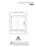
N002
10 / 2013
shower door - porte de douche
2 PEOPLE REQUIRED
2 PERSONNES REQUIS
IT IS MANDATORY TO HAVE A WALL STUD ON EACH SIDE OF THE
SHOWER UNIT TO SECURELY FASTEN THE RAIL TO THE WALLS.
IL EST OBLIGATOIRE D’AVOIR UNE OSSATURE MURALE SUR CHAQUE
CÔTÉ DE LA DOUCHE POUR FIXER LA BARRE DE ROULEMENT.
INSTRUCTION MANUAL - GUIDE D’INSTALLATION
GENERAL INSTRUCTIONS
• Read this manual carefully and completely before proceeding.
• It is recommended that you wear safety glasses at all times during the installation.
INSTALLATION OVER CERAMIC TILES
• If your shower door is to be installed over ceramic tiles, the tiles should lie completely under the wall jamb.
• Silicone should be used to seal the gap where the ceramic tiles meet the fixed panel.
En
NOTICE
• Caulking: no sealant is required inside the shower.
• Some models are equipped with clear sealing gaskets.
CARE FOR YOUR SHOWER DOOR
• Never use scouring powder pads or sharp instruments on metal pieces or glass panels. An occasional wiping down with a mild
soap diluted in water is all that is needed to keep the panels and aluminum parts looking new.
• We recommend wiping the glass panels with a squeegee after each use.
INSTRUCTIONS GÉNÉRALES
• Lire attentivement et complètement le manuel d’installation avant de procéder.
• Il est recommandé de porter des lunettes de sécurité en tout temps lors de l’installation.
Fr
INSTALLATION SUR LES TUILES EN CÉRAMIQUE
• Si votre porte de douche doit être installée sur une bordure en céramique, le jambage doit reposer complètement sur cette
dernière.
• Le calfeutrage doit être appliqué sur le côté extérieur de la douche où le panneau fixe rencontre la bordure en céramique.
NOTE
• Calfeutrage: aucun scellant n’est nécessaire à l’intérieur de la douche.
• Certains modèles sont dotés de joints d’étanchéité claire.
L’ENTRETIEN DE VOTRE DOUCHE
• Ne jamais utiliser de poudre ou de tampon à récurer, ni d’instrument tranchant sur les parties en métal ou en verre. De temps
à autre, il suffit de nettoyer la porte avec une solution d’eau et de détergent doux pour conserver l’aspect neuf des panneaux
de verre et du cadre en aluminium.
• Nous recommandons de passer une raclette de douche sur les panneaux de verre après chaque utilisation.
Product specifications are subject to change without notice.
Des changements peuvent être apportés aux produits sans préavis.
2
INSTRUCTION MANUAL - GUIDE D’INSTALLATION
TOOLS REQUIRED / OUTILS REQUIS
LONG NOSE LOCKING PLIERS
PINCE SERRE ÉTAU
SCREWDRIVERS
TOURNEVIS
1/4" & 1/8" DRILL BITS
MÈCHE 1/4˝ & 1/8"
DRILL
PERCEUSE
PENCIL
CRAYON
SILICONE
SCELLANT
CUTTING PLIERS
PINCE COUPANTE
LEVEL
NIVEAU
MALLET
MAILLET
TAPE MEASURE
RUBAN À MESURER
5/16" HEX NUT DRIVER
TOURNE-ÉCROU 5/16"
To install the shower door on ceramic tiles, use a 1/4’’ drill bit for ceramic tiles.
Pour installer la porte de douche sur des tuiles en céramique, utiliser une mèche 1/4’’ à céramique.
3
INSTRUCTION MANUAL - GUIDE D’INSTALLATION
PARTS LISTING / LISTE DES PIÈCES
9
19
16
HARDWARE / QUINCAILLERIE
18
13
5
14
20
23
24
21
22
25
6
1
11
3
8
4
7
2
12
4
17
15
10
14
19
13
16
17
15
ITEM
PARTS - PIÈCES
QTY
1
WALL JAMB (REGULAR PUNCH) - JAMBAGE (PERÇAGE RÉGULIER)
1
2
FIXED PANEL - PANNEAU FIX
1
3
UNIVERSAL EXPANDER - EXTENSEUR UNIVERSEL
1
4
FIXED PANEL GASKET - JOINT D’ÉTANCHÉITÉ PANNEAU FIXE
1
5
MIDGASKET - JOINT LATERAL
1
6
DOOR PANEL - PANNEAU DE PORTE
1
7
BOTTOM DOOR GASKET - JOINT INFÉRIEUR
1
8
DOOR SIDE GASKET - JOINT DE PORTE
1
9
RUNNING RAIL - BARRE DE ROULEMENT
1
10
DOOR FRONT THRESHOLD - SEUIL DE RÉTENTION AVANT
1
11
STRAIGHT HANDLE BAR - POIGNÉE DROITE
1
12
“U” CHANNEL - PROFILÉ EN ALUMINIUM “U”
1
13
ROLLERS - ROULETTE
2
14
ANTI-JUMP - ANTI-SAUT
2
15
DOOR RECEIVER - RÉCEPTEUR DE PORTE
1
16
DOOR STOPPER - BOUTOIR
1
17
BOTTOM GUIDE - GUIDE DU BAS
1
18
WALL MOUNT BRACKET - SUPPORT MURAL
2
19
GLASS FASTENERS - SUPPORTS DE VERRE
2
ITEM
HARDWARE - QUINCAILLERIE
QTY
20
WALL PLUG - CHEVILLE
4
21
SCREW CAP - CAPUCHON COUVRE-VIS
3
22
BACK SCREW CAP - L’ ARRIÈRE DU CAPUCHON COUVRE-VIS
3
23
PAN SELF DRILLING SCREW - VIS PAN AUTO-PERÇANTE # 8- 3/8"
3
24
PAN SELF-DRILLING SCREW - VIS PAN AUTO-PERÇANTE # 8- 1-1/4"
4
25
2 MM HEX KEY - CLÉ HEXAGONALE 2MM
1
INSTRUCTION MANUAL - GUIDE D’INSTALLATION
POSSIBLE CONFIGURATIONS / CONFIGURATIONS POSSIBLES
Recommended door panel according to showerhead location. Choose right or left door opening, according with recomandations.
Trace a centerline on the threshold of the base, making sure the bottom guide can be positioned as shown below.
Determine which side the wall jamb will be mounted.
Disposition recommandée de la porte selon la localisation de la tête de douche. Choisir l’ouverture de droite ou de gauche,
conformément aux recommandations.
Tracer une ligne centrale sur le seuil de la base. S’assurant que le guide peut être correctement positionné sur la base comme indiqué.
Déterminez de quel côté le jambage sera monté.
INTERIOR
SHOWER SIDE
INTÉRIEUR DE
LA DOUCHE
SIDE VIEW
VUE LATÉRALE
Centerline
Ligne de centre
INTERIOR
SHOWER SIDE
INTÉRIEUR DE
LA DOUCHE
the bottom guide can hang off the base
as long as it can be well fastened and is
towards the inside of the shower.
le guide inférieur peut dépasser la base en
autant qu’il puisse être bien fixé et que
et c’est vers l’intérieur de la douche.
TOP VIEW
VUE DU HAUT
17
5
INSTRUCTION MANUAL - GUIDE D’INSTALLATION
1
VvVV
Door Panel Assembly / assemblage de la porte coulissante
1a Use a mallet to install the bottom gasket (7)
on the bottom of the door panel (6). To
facilitate installation place the door panel on
the cardboard packaging box and use it as
platform. Notice that the holes are situated at
the top of the door panel.
6
1a
DOOR HANDLE HOLES
TROUS DE POIGNÉE DE PORTE
7
1b Measure and cut 3/8" off the edge of the
gasket. Cut on the opposing side of the door
handle holes.
3/8’’
1c Install both rollers (13) through the top holes
of the door panel. Be sure that the adjustment
wheels are turned on the position of the
minimum thickness that is orientated towards
the bottom.
1b
1d Install the door handle (11). Holes for the
screws are located on the back of the handle
that must be located on the interior of the
shower area.
1a
À l’aide d’une mallette, insérer le joint
inférieur de porte (7) à la porte coulissante
(6). Pour faciliter la tâche, veuillez utiliser la
boîte d’emballage en carton comme
plateforme. Noter bien que les trous de la
porte sont situés à la partie supérieure de la
porte.
1c
MINIMUM THICKNESS
ORIENTED TOWARDS
THE BOTTOM
INTERIOR
SHOWER SIDE
INTÉRIEUR DE
LA DOUCHE
ÉPAISSEUR MINIMUM
ORIENTÉE VERS LE BAS
!!
1b Mesurer et couper un bout de 3/8" du joint
inférieur de porte à partir du bord inférieur
opposé aux trous de poignée.
1c Installer les deux roulettes (13) à travers les
deux trous supérieurs du panneau de porte.
Assurer que les épaisseurs minimums des
roulettes d’ajustement sont positionnées vers
le bas.
1d Installer la poignée de porte (11). Les trous
pour les vis sont situés à l’arrière de la
poignée qui doit être situé à l’intérieur de la
zone de la douche.
13
1d
11
INTERIOR
SHOWER SIDE
THE INSTALLATION SHOWN IS BASED ON
PLUMB FINISHED WALLS AND A LEVELLED
BASE. IF THESE CONDITIONS ARE NOT MET,
PLEASE ADJUST ACCORDINGLY.
L’INSTALLATION ILLUSTRÉE EST BASÉE SUR
DES MURS FINIS D’APLOMB ET UNE BASE DE
DOUCHE NIVELÉE. SI CES CONDITIONS NE
SONT PAS PRÉSENTÉES, VEUILLEZ AJUSTER
EN CONSÉQUENCE.
6
INTÉRIEUR DE
LA DOUCHE
INTERIOR
SHOWER SIDE
INTÉRIEUR DE
LA DOUCHE
INSTRUCTION MANUAL - GUIDE D’INSTALLATION
1
1e
1e
2
Door Panel Assembly (CONTINUED) / assemblage de la porte coulissante (suite)
Place door panel (6) inside the shower area to
simplify the following installation procedures.
Place the panel on a cushioned surface, such as
a towel or carboard, to prevent damage either to
the panel or to the base.
1e
6
Placer le panneau de porte coulissante (6) à
l’intérieur de la zone de douche afin de simplifier
les étapes à suivre. Placer le panneau sur une
surface plane et rembourrée, comme une serviette ou un carton, pour éviter tout dommage, soit
au panneau ou à la base.
!!
CARBOARD OR TOWEL
TO PROTECT
CARTON OU SERVIETTE
POUR PROTÉGER
RUNNING RAIL / BARRE DE ROULEMENT
2a
Unfasten the set screws (x4) from each of the
wall brackets (18). Remove the back plates
from the wall brackets and set them aside.
2b
Slide the wall brackets away from the ends of
the running rail (9) as illustrated.
2a
Dévisser les vis (x4) des supports muraux (18).
Retirer les plaquettes du chaque support mural
(x2) et les mettre de côté.
2b
Avec les plaquettes retirées, glisser les
supports muraux au long de la barre de
roulement (9) tel qu’illustré.
2a
2b
18
9
7
INSTRUCTION MANUAL - GUIDE D’INSTALLATION
3
3a
3b
3a
3b
FIXED Panel Assembly / assemblage dU PANNEAU FIXE
Assemble the fixed panel to
the running rail. Align running
rail holes with the holes of
the fixed panel. Install glass
fasteners(19) to join the fixed
panel(2) and the running rail
(9). Be sure to place gaskets
between all contact with glass
and metal parts. Fasten with
3mm hex key.
9
19
2
Place “U”-channel (12)
temporarily on the bottom of
the fixed panel (2). Slide the
fixed panel pre-assembled
with expander (3) and gasket
(4) into the wall jamb (1). Level
the glass panel assembly with
the wall jamb.
Assemblez le panneau fixe
avec la barre de roulement.
Aligner les trous de la barre
de roulement avec les trous du
panneau fix. Installez les supports vitreux (19) pour joindre
le panneau fixe (2) à la barre
de roulement (9). Assurer à
placer les joints entre tout contact du verre avec les pièces
en métal.Serrer à l’aide de la
clé hexagonale 3mm.
SIDE VIEW
VUE LATÉRALE
3a
19
INTERIOR
SHOWER SIDE
19
INTÉRIEUR DE
LA DOUCHE
INTERIOR
SHOWER SIDE
INTÉRIEUR DE
LA DOUCHE
3b
9
Positionnez temporairement le
rail inférieur (12) sur la partie
inférieure du panneau fixe (2).
Glisser le panneau fixe (2)
préassemble de l’extenseur (3)
et du joint (4) dans le jambage
(1). Assurer le niveau du panneau fixe à l’aide d’un niveau.
2
9
SIDE VIEW
VUE LATÉRALE
19
1
INTERIOR
SHOWER SIDE
INTÉRIEUR DE
LA DOUCHE
12
8
2
INSTRUCTION MANUAL - GUIDE D’INSTALLATION
3
FIXED Panel Assembly (continued) / assemblage dU PANNEAU FIXE (SUITE)
3c
Temporarily reassemble
the angled wall back plate
to the wall bracket on the
running rail. Temporarily
place bottom guide (17)
on the bottom of the fixed
panel (2).
3d
Temporarily place the fixed
panel assembly on the
threshold of the base on the
line that was marked previously. Push wall brackets
against wall (x2) and level.
3e
Trace the outer edges of the
wall brackets (x2).
3c
Réinstaller temporairement
la plaquette au support
mural en angle sur la barre
de roulement. Positionner
temporairement le guide du
bas (17) sur la partie
inférieure du panneau
fixe (2).
3d
3e
Placer temporairement
l’assemblage du panneau fixe sur le seuil de la
base sur la ligne marquée
précédemment.Glisser les
supports muraux jusqu’au
mur (x2) et mettre a niveau.
3d
3c
TOP VIEW
VUE DU HAUT
17
2
3e
Tracer le contour extérieur
des supports muraux (x2).
INTERIOR
SHOWER SIDE
INTÉRIEUR DE
LA DOUCHE
9
INSTRUCTION MANUAL - GUIDE D’INSTALLATION
4
WALL JAMB INSTALATION / INSTALLATION DES JAMBAGES
4a
Push the wall jamb against the wall. Lock into position by clamping the wall jamb and expander with pliers. Trace the position of the
wall jamb on the wall as illustrated. Trace the position of the “U”-channel (12) and of the bottom guide (17) on the threshold of the base.
Mark the location of the bottom guide’s hole.
4b
Remove the fixed panel assembly with the running rail along with the wall jamb , wall brackets the “U”-channel and the bottom guide.
Put aside. Remove the gasket from the bottom guide.
4a
Pousser le jambage contre le mur. Barrer la position du jambage et de l’extenseur à l’aide des pinces autobloquantes. Tracer la
position de jambage sur le mur comme illustré. Tracer la position du guide du bas (17) et du trou et du profilé en aluminium (12) sur
le seuil de la base comme illustré.
4b
Enlever le panneau fixe avec le jambage, la barre de roulement et les supports muraux, ainsi que le guide du bas et le profilé en
aluminium (12). Mettre de côté. Enlever le joint du guide de bas.
4a
TOP VIEW
VU DU HAUT
4b
THE BACK OF BOTTOM GUIDE (17) MUST BE
PLACED AT THE SAME LEVEL WITH INNER
THRESHOLD OF SHOWER BASE.
LE DOS DU GUIDE DE BAS (17) DOIT ETRE
PLACÉ AU MEME NIVEAU QUE LE SEUIL
INTÉRIEURE DE LA BASE DE DOUCHE
INTERIOR
SHOWER SIDE
INTÉRIEUR DE
LA DOUCHE
COVER THE
PLIER’S TEETH
BEFOREHAND
TO AVOID
SCRATCHING THE
ALUMINUM PARTS.
RECOUVRER LES
DENTS DE LA
PINCE AFIN
DE NE PAS
GRAFIGNER LES
PIÈCES
EN ALUMINIUM.
INTERIOR
SHOWER SIDE
INTÉRIEUR DE
LA DOUCHE
10
INSTRUCTION MANUAL - GUIDE D’INSTALLATION
4
WALL JAMB INSTALATION (CONTINUED) / INSTALLATION DES JAMBAGES (SUITE)
4c Replace the wall jamb against wall using
centerline previously marked as a guide.
Be sure to center the slotted holes with the
centerline. Level and mark locations of the
four holes to be drilled. Remove the wall jamb.
4c
1
4d Drill a hole in each location with a 1/4" drill bit.
Insert one drop of silicone in each hole in the
4e wall before inserting the supplied wall plugs (x4).
4c Placer le jambage sur le seuil en centrant les
trous du jambage avec la ligne centrale tracée.
Ceci assure une position droite du jambage.
Tracer les quatre emplacements de perçage.
Enlever le jambage.
4d Percer les trous avec une mèche de 1/4".
4e Introduire une goutte de silicone dans chaque
trou percé dans le mur avant d’y insérer une
cheville (x4) dans chaque trou.
4d
4e
20
CERAMIC TILE
INSTALLATION
USE A DRILL BIT FOR
CERAMIC TILES.
POUR INSTALLATION
SUR CARREAUX DE
CÉRAMIQUE,
UTILISER UNE MÈCHE
POUR TUILE DE
CÉRAMIQUE.
11
INSTRUCTION MANUAL - GUIDE D’INSTALLATION
4
4f
WALL JAMB INSTALATION (CONTINUED) / INSTALLATION DES JAMBAGES (SUITE)
Add silicone to the exterior bottom edge
of the wall jamb.
4f
4g
4g Fasten the wall jamb to the wall with
1-1/4" screws (24) through the previously installed wall plugs. (x4)
4h Add silicone to interior bottom edge of
wall jamb.
4f
24
Ajouter du silicone à la base extérieure
du jambage.
4g Visser le jambage au mur avec les
vis de 1-1/4" (24) dans les chevilles
précédemment installées. (x4)
4h Ajouter du silicone à la base intérieure
du jambage
INTERIOR
SHOWER SIDE
4h
INTÉRIEUR DE
LA DOUCHE
7a
5
5a
5b
WALL bracket BACK PLATE / PLAQUETTE ARRIERE DU SUPPORT MURAL
Align the back plates of the wall
brackets to previously traced
lines on the wall. Trace the hole
centers to determine drilling
location (x2). Remove the back
plates.
5a
Drill marked holes in walls by
using the 1/4" drill bit.
INTERIOR
SHOWER SIDE
12
5a
Aligner les plaquettes arrière des
supports muraux à la ligne tracée
antérieurement sur le mur (x2).
5b
Tracer le centre des trous au mur
pour déterminer l’emplacement
de fraisage. Enlever les plaquettes arrière. Percer des trous
avec une mèche de 1/4".
INTÉRIEUR DE
LA DOUCHE
5b
INTERIOR
SHOWER SIDE
INTÉRIEUR DE
LA DOUCHE
INSTRUCTION MANUAL - GUIDE D’INSTALLATION
5
WALL bracket BACK PLATE (CONTINUED) / PLAQUETTE ARRIERE DU SUPPORT MURAL (SUITE)
5c Insert one drop of silicone in each hole bored
in the wall before inserting the wall plugs.
5d
5c
5d Screw in flat head screws through holes to
secure back plate of bracket to wall. (x2)
5c Introduire une goute de silicone dans chaque
trou percé avant d’y insérer une cheville. (x2)
5d Viser les plaquettes arrière des supports
muraux au mur avec les vis à tête plate. (x2)
Same procedure for opposite
side of wall
mÊme pour bord opposé
6
“U” - channel location / emplacement du profilÉ en aluminum
6a
Remove protective film on pre-applied
adhesive tape underneath of “U”-channel (12).
6b
Place the “U”-channel against the wall
jamb and align it to the line marked
previsouly on base.Then press down to
secure to the base.
6a
6b
6a Enlever le film protecteur du ruban ad-
hésif préappliqué en dessous du profilé
en “U” (12).
6b Placer le profilé en aluminium contre le
jambage tel qu’illustré. Aligner le bout
du profil en aluminium avec les lignes
tracées antérieurement. Appliquer une
pression au profilé pour bien le
sécuriser en place.
12
CLEAN BASE THRESHOLD SURFACE PRIOR
TO BONDING “U” CHANNEL.
NETTOYER LA SURFACE DU SEUIL AVANT DE
COLLER LE PROFILÉ EN “U”.
13
INSTRUCTION MANUAL - GUIDE D’INSTALLATION
7
bottom guide installation / installation du guide du bas
7a
Place bottom guide to the edge of the “U”-Channel. Center the front bottom guide channel to the center of the “U”-Channel. Once in
place mark hole location and remove bottom guide.
7b
Drill with 1/8" drill bit in marked location, then apply a drop of silicone in hole.
7c
Reposition bottom guide and secure in place. Top with screw cap.
7d
Place the gasket in the bottom guide.
7a
Placer le guide du bas sur le bord du profilé en aluminium, aligner le centre du devant du guide avec le centre du profilé en aluminium.
Tracer l’emplacement du trou. Retirer le guide du bas.
7b
Percer un trou avec une mèche de 1/4" et puis y appliquez une goute de silicone.
7c
Repositionner le guide du bas et le viser en place avec la vis fournie. Ajouter le capuchon à vis.
7d
Insérer le joint dans le guide du bas.
7a
INTERIOR
SHOWER SIDE
INTÉRIEUR DE
LA DOUCHE
17
7c
7b
INTERIOR
SHOWER SIDE
INTÉRIEUR DE
LA DOUCHE
INTERIOR
SHOWER SIDE
INTÉRIEUR DE
LA DOUCHE
14
7d
INSTRUCTION MANUAL - GUIDE D’INSTALLATION
8
FIXED PANEL INSTALLATION / INSTALLATION DU PANNEAU FIXE
8a
Install the fixed panel. Insert the
8a
running rail into the wall bracket
back plates that were installed
previously. Insert the glass panel
in the front bottom guide channel.
8b
Push wall brackets towards the
wall and lock in with the back
plates previously secured to the
wall. Repeat on opposite side.
8c
Tighten set screws to secure in
place with allen key provided.
(X8)
8a
Installer le panneau fixe. Insérer
la barre de roulement avec les
supports muraux dans les plaquettes arrière montées au mur.
Insérer le panneau de verre dans
le guide du bas.
8b
Glisse les supports muraux contre le mur et insérez-les dans les
plaquettes arrière.
8c
Serrer les vis pour sécuriser
l’emplacement des supports muraux et pour bien sécuriser
la barre.
8b
TOP VIEW
VU DU HAUT
8c
15
INSTRUCTION MANUAL - GUIDE D’INSTALLATION
9
secure the wall jamb and expander / securiser le jambage
9a
Drill a hole through the wall jamb with a 1/8" drill bit
to pierce through the expander. (x3)
9b
Screw 3/4" screws (23) through holes to hold expander and wall jamb together in place. (x3) Cover
all screws with screw caps (21).
9a
Percer l’extenseur à travers les trous du jambage
avec une mèche de 1/8". (x3)
9b
Viser les vis de 3/4" (23) dans les trous pour tenir
l’extenseur et le jambage ensemble. Couvrir avec
les capuchons couvre-vis (21).
9a
INTERIOR
SHOWER SIDE
24
21
22
9b
INTÉRIEUR DE
LA DOUCHE
21
23
10
door panel installation / installation du panneau de porte
10a
Install door panel (6) by
aligning the rollers (13) on
running rail (9) and by aligning the door panel (6) with
the back channel of bottom
guide (17).
10b
10a
10b
13
6
Slide door to insure a smooth
stable glide.
10a Installer le panneau de porte
9
(6) en alignant les roulettes
(13) sur la barre de roulement (9) et en alignant le
panneau de porte avec le
seuil intérieur du guide du
bas (17).
Faire glisser la porte pour
10b assurer l’aise avec laquelle
la porte glisse sur la barre
de roulement.
17
INTERIOR
SHOWER SIDE
INTÉRIEUR DE
LA DOUCHE
16
INSTRUCTION MANUAL - GUIDE D’INSTALLATION
11
11a
11b
11c
11d
11a
11b
11c
11d
door gaskets installation / installation des joints au panneau de porte
Temporarily install midgasket
(5) and the door gasket (8) to
door panel.
11a
Close door entirely, mark
interference of the gaskets
with the running rail.
Cut gasket at marked
locations using cutters. Note
that midgasket (5) needs only
to be cut below the running
rail. The top part is no longer
required for assembly.
5
8
Remove gasket from panel
Before cutting.
Retirer le joint du panneau avant de procéder à
la coupure.
Reinstall gaskets from
bottom working your way up.
Use a mallet to insure that
the gaskets are fully pushed
onto glass panel door.
Installer temporairement le
joint latéral (5) et le joint de
porte (8) sur le panneau de
porte.
INTERIOR
SHOWER SIDE
INTÉRIEUR DE
LA DOUCHE
11b
5
8
Avec la porte bien fermée,
tracer l’interférence des
joints avec la barre de
roulement.
Couper les joints sur la
ligne tracés. Noter que le
joint latéral suffit d’être
coupé à la partie
inférieure. La partie
supérieure du joint
n’est pas requise pour
l’assemblage.
Réinstaller les joints sur la
porte, débuter par le bas
et puis monter. Utiliser un
maillet pour assurer que
les joints soient bien fixés
au panneau de porte.
INTERIOR
SHOWER SIDE
INTÉRIEUR DE
LA DOUCHE
5
11c
8
11d
17
INSTRUCTION MANUAL - GUIDE D’INSTALLATION
126 anti-jump & door stopper / Anti-saut & butoir
12a
12b
Install anti-jump (14) in lower holes of door
panel located below the running rail. Be sure
to place gaskets between contact of glass and
aluminium parts. (x2)
12a
INTERIOR
SHOWER SIDE
Install door stopper (16) located in the interior
shower next to wall jamb. Use hole provided in
running rail.
12a
Installer l’anti-saut (14) dans les trous inférieurs du panneau de porte se trouvant dessous la barre de roulement. Assurer d’avoir
des joints entre tout contact d’aluminium et de
verre. (x2)
12b
Installer le butoir (16) dans la partie intérieure
de la douche. Celui-ci se trouve à côté du
jambage. Utiliser le trou situé dans la barre de
roulement.
INTÉRIEUR DE
LA DOUCHE
14
gaskets
joints
INTERIOR
SHOWER SIDE
INTÉRIEUR DE
LA DOUCHE
12b
INTERIOR
SHOWER SIDE
INTÉRIEUR DE
LA DOUCHE
16
18
INTERIOR
SHOWER SIDE
INTÉRIEUR DE
LA DOUCHE
INSTRUCTION MANUAL - GUIDE D’INSTALLATION
13 door receiver intallation / installation réceptrice de porte
13a Place door receiver (15) against the wall,
so that the door panel slides smoothly into
the receiver. Mark hole location.
13b
13a
13b Remove door receiver and drill in marked
location with 1/8" drill bit.
15
13c Insert one drop of silicone into hole.
13d Reposition and secure in place with
provided screw then place the screw cap.
13a Placer le récepteur de porte (15) contre
le mur, placé en sorte que la porte glisse
aisément dans le récepteur. Tracer le trou
du récepteur.
13c
13d
13b Retirer le receveur et percer à l’endroit
indiqué avec une mèche de 1/8".
13c Insérer une goutte de silicone dans le trou.
13d Repositionner et viser la vis pour tenir en
place. Rajouter le capuchon à vis.
14
14a
THRESHOLD / SEUIL DE RÉTENTION
Place threshold (10) between wall and
bottom guide as shown in figure 14a.
Cut off any excess length.
14b
Apply silicon on the bottom of threshold as indicated in 14b. Secure threshold in place.
14a
Placer le seuil de rétention entre le mur
et le guide du bas comme l’indique la
figure 14a. Couper l’excès du seuil
pour que le seuil rentre parfaitement
en place.
14b
Appliquer le silicone sous le seuil de
rétention et puis installer en place.
Cut only if necessary
14a
couper seulement si
necessaire
10
14b
INTERIOR
SHOWER SIDE
INTÉRIEUR DE
LA DOUCHE
19
INSTRUCTION MANUAL - GUIDE D’INSTALLATION
15
sealing / calfeutrage
15a Silicone the outside of the shower unit along the wall jamb and the exterior side of aluminum threshold and “U”-channel.
15b Wait 24 hours before using the shower to allow silicon to dry.
15a Calfeutrer avec du silicone l’extérieur de l’unité autour du jambage et à l’extérieur du seuil en aluminium et du profil en aluminium.
15b Attendre 24 heures avant de faire fonctionner la douche afin que le silicone sèche.
15a
15b
HOURS
HEURES
20