1
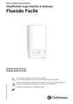
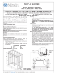
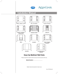
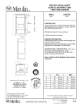
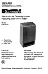
DELUXE JET AIR
THERAPEUTIC AIR
Air Massage and Whirlpool Combinations
INSTALLATION AND OPERATING INSTRUCTIONS
READ ALL INSTRUCTIONS CAREFULLY BEFORE STARTING THE INSTALLATION OF YOUR
AIR MASSAGE / COMBINATION BATH.
PLEASE RECORD THE SERIAL NUMBER______ OF YOUR AIR MASSAGE BATH AND SAVE THIS MANUAL
FOR FUTURE REFERENCE.
NOTE: These instructions are to be used along with the installation
instructions for ACRYLIC BATHTUBS.
WARNING - When using electrical products, basic precautions
should always be followed, including the following:
1.
DANGER: RISK OF ELECTRICAL SHOCK.
Connect only to a circuit protected by a ground fault
circuit interrupter, (GFCI).
2.
3.
Grounding is required. An equipment grounding
terminal is provided in the field wiring compartment. To
reduce the risk of electric shock, this terminal must be
connected to the grounding means provided in the
electric supply panel with a conductor equivalent in size
to the circuit conductors supplying the equipment.
INSTALL THIS UNIT IN ACCORDANCE WITH THE
CANADIAN ELECTRICAL CODE, PART 1 OR THE
APPROPRIATE CODE IN OTHER COUNTRIES.
4.
INSTALL TO PERMITACCESS FOR SERVICING.
5.
Provide adequate ventilation for the motor to prevent
nuisance trips of the thermal overload protection.
Relocating the blower or pump will void the warranty.
NOTE: The unions for the piping at the pump on the
combination units are only to be hand tightened. Check by
hand that they have not loosened during shipping.
MODELS WITH INTEGRAL APRON
Air massage baths with an integral apron have a removable
panel in the apron for access to the blower and pump.
Depending on the design of the whirlpool the panel is
fastened to the apron by either of the following:
!
Strips of interlocking fabric (velcro) along the top
with plastic clips on the bottom (Figure 1).
!
Screws (Figure 2).
In either case, to remove panel follow instructions below:
Panel with strips of interlocking fabric: gently pull the panel
away starting from the top.
To replace the panel, position the removable panel onto
lower flange and press into place against the velcro pads.
INSTALLATION NOTES
Important: All Acrylic Air Massage baths receive a thorough water
test and are carefully inspected and packed for shipment. You
should check your unit for any problems. Contact your dealer
before installation.
Figure 1 - Removable Centre Panel
REMOVABLE
PANEL
VELCRO
Protect the bathtub and fittings from dirt and damage by leaving
the polyethylene protective film in place until installation and
other related construction are complete.
Caution: Do not lift an air massage bath or whirlpool by its
plumbing. Handle it by the bath shell only.
Access for servicing the Blower/Pump and Controls of the air
massage bath must be provided (Refer to specification drawings
for location). DO NOT remove or relocate the blower or pump
from its factory-installed position. This position ensures proper
priming, drainage, and performance of the air massage or
combination system.
CLIP
APRON FRAME
1
© Copyright 2010 Mirolin Ind. The Copyright includes all content on the document.
2
3
1
INSTALLATION INSTRUCTIONS (continued)
Plastic cap
MODELS WITH INTEGRAL APRON
Removable panel fastened with screws:
This instruction applies to the following models only:
PHOENIX SERIES
TUCSON SERIES
BA5 L/R
SYDNEY L/R
ADORA L/R
KD 53 L/R
VIC 53 L/R
BA 604T L/R
TS 5 L/R
PT520 L/R
PT516 L/R
To remove the panel, first expose the screws by
removing all the 5 plastic caps. Use a flat
screwdriver gently to avoid scratching the acrylic
bathtub.
Figure 3.
Figure 2 - Integral apron with removable panel
fastened with screws
Figure 4 shows the exposed screw fastened on the
acrylic apron.
To remove the panel, loosen the screws by using a
Phillip’s screwdriver.
Figure 5.
Note:
Plastic caps are color-enhanced and for illustration
purposes only.
Plastic caps are color-matched based on the color of
the acrylic bathtub.
Figure 4 - Exposed screw on the integral apron
Figure 3 - Unplug the plastic caps
Figure 5 - Remove the screw with a Phillip’s screwdriver
ELECTRICAL AND TESTING
ELECTRICAL
WARNING: FOLLOW ALL ELECTRICAL SAFETY REQUIREMENTS LISTED AT THE BEGINNING OF THE
INSTALLATION SECTION OF THIS MANUAL.
Have a licensed electrician make the electrical installation to ensure that all the minimum requirements of the local electrical
safety codes are met.
NOTE: All controllers shall be fastened to an adjacent stud 102 mm (4") above the floor.
2
INSTALLATION INSTRUCTIONS (continued)
B1 - 110V POWER SUPPLY
B2 - 110V POWER SUPPLY
1- BLACK
1- WHITE (NEUTRAL)
1 - GREEN (GROUND)
CONTROL
BOX
(WHIRLPOOL)
1- BLACK
1- WHITE (NEUTRAL)
1 - GREEN (GROUND)
WHIRLPOOL PUMP
B
B
G G
W
110V, 15 A FROM
SERVICE PANEL
GFCI
110V, 15 A FROM
SERVICE PANEL
GFCI
ELECTRONIC
TOUCH PAD
CONTROL
(COMBINATION)
on
on
1
off
off
on
W
2
off
TM
B B
W W
G G
R
CONTROL
BOX
(JET AIR)
B1 - 110V POWER SUPPLY
B B
W W
G G
1- BLACK
1- WHITE (NEUTRAL)
1 - GREEN (GROUND)
B2 - 110V POWER SUPPLY
1- BLACK
1- WHITE (NEUTRAL)
1 - GREEN (GROUND)
BLOWER
Figure 6 - Air Massage/Whirlpool
Combination Connections
ELECTRICAL CONNECTIONS
Air Massage
Air Massage / Whirlpool Combination
The installation must conform to the local electrical safety
codes. The following are general requirements only, they
do not cover all details or all situations.
The air massage blower and the whirlpool pump each
require a 15A, 115V circuit, that is, 2 separate lines from
the service box with Class A GFCI protection.
The standard requirement is a separate 15A, 115V circuit
protected by a Class A GFCI rated for 15A.
The cable from the service box is to be 14/2 wire which is
satisfactory for distances up to 100 ft. (30 m).
The cable from the service box is to be 2 wires plus a
ground. # 14 conductor is satisfactory for distances up to
100 ft. (30 m).
If the local codes require a disconnect switch it must be a
duplex switch installed in the service compartment
mounted to a stud and not directly to the tub.
For air massage, electrical connection is a standard class
A GFCI - NEMA receptacle.
ELECTRONIC CONTROL, AIR MASSAGE AND
COMBINATION
Some local codes may require a disconnect switch. This
can be installed in the wall or near the motor in the service
compartment.
The deck mounted touch-pad control on the Air Massage
and Combination model is connected to two pin plugs
made at the factory. Check underneath the deck that the
pin plugs are connected accordingly.
If installed in the wall it must be at least 1.5 m (5 ft.) away
from the tub so that a person in the tub cannot reach it.
If installed in the service compartment it should be
mounted to a stud and not directly under tub.
The switch may be a standard wall switch as long as the
ampere rating is at least as great as the ampere
protection rating noted above.
3
OPERATING INSTRUCTIONS
IMPORTANT SAFETY INSTRUCTIONS
READ AND FOLLOW ALL INSTRUCTIONS
SAVE THESE INSTRUCTIONS
1.
2.
3.
4.
5.
6.
WARNING: RISK OF ACCIDENTAL INJURY OR DROWNING; CHILDREN SHOULD NOT USE MASSAGE
BATHTUB WITHOUTADULT SUPERVISION;
WARNING: RISK OF ACCIDENTAL INJURY OR DROWNING; DO NOT USE WHIRLPOOL BATHTUB UNLESS
ALL SUCTION GUARDS ARE INSTALLED TO PREVENT BODYAND HAIR ENTRAPMENT;
WARNING: TO AVOID INJURY, EXERCISE CARE WHEN ENTERING OR EXITING THE MASSAGE BATHTUB;
WARNING:
RISK OF ELECTRIC SHOCK; DO NOT PERMIT ELECTRIC APPLIANCES ( SUCH AS A HAIR
DRYER, LAMP, TELEPHONE, RADIO OR TELEVISION) WITHIN 1.5 m (5 ft.) OF THIS MASSAGE BATHTUB;
CAUTION: TEST THE GROUND FAULT CIRCUIT INTERRUPTER PROTECTING THIS APPLIANCE
PERIODICALLY IN ACCORDANCE WITH THE MANUFACTURER’S INSTRUCTIONS;
WARNING: RISK OF HYPERTHERMIA AND POSSIBLE DROWNING: WATER TEMPERATURE IN EXCESS OF
38º C (100º F) MAY BE INJURIOUS TO YOUR HEALTH. CHECK AND ADJUST WATER TEMPERATURE BEFORE
USE.
FOLLOW ALL SAFETY INSTRUCTIONS IN THIS MANUAL
SAFE USE OF AN AIR MASSAGE OR WHIRLPOOL
Your physiological response to a hot air massage or whirlpool bath depends on your age, health and medical history. Initially,
stay in the bath for a short time only until you learn your tolerance for hot water. If you develop a headache or become dizzy or
nauseous, get out at once and cool off under a shower. Get medical help if symptoms persist.
Consult your doctor before you use the air massage or whirlpool for physical therapy of an injury or disorder. Don’t take an air
massage or whirlpool bath without your doctor’s consent if you are ill or pregnant, or if you suffer from high blood pressure,
heart disease, or other health problems. Never take an air massage or whirlpool bath while under the influence of medication,
drugs, or alcohol.
WARNING
DO NOT RUN THE WHIRLPOOL PUMP UNLESS THE BATH IS FILLED WITH WATER TO A LEVEL OF 2” (50 mm)
ABOVE THE WHIRLPOOL FITTINGS.
Use only small amount of soap or other bath preparation in whirlpool baths, otherwise excessive foaming may occur.
SUCTION
DO NOT BLOCK SUCTION INLET SCREEN ON WHIRLPOOL BATHS.
Water is circulated back to the pump from this location. Should the inlet screen become blocked in any way the safety suction
will engage and the pump will start cavitating.
The pump will immediately shut down stopping the flow, thus releasing whatever is blocking the screen.
When the screen is free of blockage, the pump will automatically start up and the system is back to normal.
Under no circumstance is the pump to be used without the screen on the suction return.
OPERATING CONTROLS
The Air Massage and Air Massage/ Whirlpool Combinations have electronic touch pad controls.
There is a heating element within the blower that heats the air in the reservoir to 40°C (104°F), to prevent the water from
cooling too fast. It will not, under any circumstances, reheat or maintain the temperature of the bath water.
NOTE: 20 minutes after the blower is shut off automatically or by the on/off control, the blower will come on again for 30
seconds to dry the air jets.
If the tub has not been drained at the time it will be necessary to run the blower manually for 30 seconds to dry the
jets after the tub is drained.
4
OPERATING INSTRUCTIONS (continued)
Motor Protection
The blower and pump motors are equipped with a built-in
thermal overload protector to shut off the motor in the
event the temperature becomes excessive (as a result of
mechanical or electrical problems; such as low voltage,
poor ventilation, overload lines, etc.). The motor will
restart automatically as it cools down.
Whirlpool Fittings
Use a finger to swivel the whirlpool jet to give the direction of
flow required. Do not plug the whirlpool fittings while the
pump is running.
The flow of water can also be increased by turning the jet face
plate clockwise and decreased by turning counterclockwise.
Refer to Figure 7.
Caution: The whirlpool jets can be misadjusted to throw
a stream of water out of the tub, onto the floor.
Drain the Bath
Check that the pump is not running. Drain the whirlpool bath
after each use. It is not a spa that can retain its water for
repeated use through continuous filtration, heating and
chemical treatment.
FIGURE 7- ADJUSTABLE FLOW WHIRLPOOL JET
ELECTRONIC TOUCH PAD CONTROL
Air Massage Deluxe
Press this key to start or stop the
blower. They always start at maximum
speed.
on
off
Press and hold this key to increase or
decrease the blower speed until
desired level.
1
2
1st press, speed will vary gradually
from maximum to minimum and back
to maximum.
2nd press, system turns off and on,
alternately.
3rd press, returns to maximum speed.
on
off
1
2
R
TM
The system will stop automatically after 20 minutes.
Advanced function:
An automatic drying cycle will start 20 minutes after the blower is turned off.
Air Massage Deluxe and Whirlpool Combination
Press this key to start the pump.
They always start at maximum speed.
on
on
on
1
off
off
off
on
on
on
Press this key to start or stop the
blower. They always start at maximum
off
off
speed.
Press and hold this key to increase or
decrease the blower speed until
desired level.
1
2
Press this key to stop the pump.
2
off
TM
R
The system will stop automatically after 20 minutes.
Advanced function:
An automatic drying cycle will start 20 minutes after the blower is turned off.
1st press, speed will vary gradually
from maximum to minimum and back
to maximum.
2nd press, system turns off and on,
alternately.
3rd press, returns to maximum speed.
5
OPERATING INSTRUCTIONS (continued)
IN-LINE BATH HEATER (Optional)
INTRODUCTION
W
Your AquaHeat Whirlpool Bath Heater utilizes “Smart
Technology” to offer you years of bathing pleasure. The
advanced electronic design provides trouble free operation
and precise control of water temperature.
B
G
There are no adjustments necessary, after the whirlpool is
filled with hot water the advanced AquaHeat Whirlpool Bath
Heater will maintain 104°F water temperature. To cool the
water simply add cold water as desired.
NOTE: The whirlpool must be running for the Heater to
function - It is controlled by a vacuum switch.
High Limit Protection
In the event the water temperature exceeds 114°F the heater
will automatically shut-off. To reset, wait until the water
temperature drops below 104°F, then remove power from
the heater by resetting the circuit breaker at the main
electrical panel. If the High-Limit trips frequently, contact a
qualified service technician.
Vacuum Switch
In the event the pump is not running or if there is not
sufficient flow, the heater will not turn ON. To correct contact
a qualified service technician.
IMPORTANT ELECTRICAL INSTRUCTIONS
WARNING - when using electrical products, basic
precautions should always be followed including the
following:
Specifications:
B - BLACK
G - GREEN
W - WHITE
1.5 kW “Inline”
115 Volt, 20 Amp
Vacuum switch
"
"
ELECTRICAL CONNECTION
Branch
Circuit
20A/115V
HOT - BLACK
GND - GREEN
COM - WHITE
TEST
GFCI
W
"
"
"
"
DANGER: RISK OF ELECTRIC SHOCK. Connect
only to a circuit protected by a ground fault circuit
interrupter, (GFCI).
Use copper conductors only.
Grounding is required. Make certain the Heater
and Pump are properly grounded and the pump
is BONDED as required.
The heater must be installed by a qualified
electrician in accordance with the National
Electrical Code and any local codes.
CAUTION
Before operating the pump/heater, test the GFCI by
pressing the “TEST” button, the pump and heater should
not operate. To resume operation press the “RESET”
button. If the GFCI fails to operate as described above,
there is ground current flowing, DO NOT operate the
pump/heater until this condition is corrected.
B
G
TO JETS
FROM
SUCTION
PUMP
INSTALLATION: IN-LINE FROM SUCTION VERSION
6
OPERATING INSTRUCTIONS (continued)
IMPORTANT SAFETY INSTRUCTIONS
WARNING - When using this unit, basic precautions
should always be followed, including the following:
1. READ AND FOLLOW ALL INSTRUCTIONS.
2. DANGER - To reduce the risk of drowning , do not
permit children to use the whirlpool bath unless they are
supervised by an adult at all times.
3. Use this heater for its intended use as described in this
Manual. Do not alter this heater or electrical shock may
occur.
4. Do not operate the Whirlpool bath or this heater with
suction covers removed, make certain the suction covers
are properly installed before use.
5. The heater must be connected to a supply circuit that is
protected by a ground fault circuit interrupter, (GFCI). The
GFCI should be provided by the installer and should be
tested on a routine basis.
To Test the GFCI press the “TEST” button, the pump and
heater should NOT operate. Press the “RESET” button
and the pump and heater should resume operation. If the
GFCI fails to operate in this manner, there is a ground
current flowing, indicating the possibility of an electrical
shock. DO NOT use the pump and heater. Have the
problem corrected by a qualified electrician before using.
6. Prolonged immersion in hot water may induce
hyperthermia. The causes, symptoms, and effects of
hyperthermia may be described as follows:
Hyperthermia occurs when the internal temperature of the
body reaches a level several degrees above normal body
temperature of 98.6°F. The symptoms of hyperthermia
include:
a) An increase in the internal temperature of the body
b) Dizziness
c) Fainting
The effects of hyperthermia include:
a) Failure to perceive heat
b) Failure to recognize the need to exit the bath
c) Unawareness of impending hazard
d) Fetal damage in pregnant women
e) Physical inability to exit the bath
f) Unconsciousness resulting in the danger of drowning
WARNING - Use of alcohol, drugs or medication can
greatly increase the risk of fatal hyperthermia.
7. To avoid potential damage: pregnant or possibly
pregnant women should consult a physician before using
the whirlpool. Water temperature in excess off 100°F is
not recommended.
8. The bath water temperature should not exceed 104°F.
Lower temperatures are recommended for extended use
(10-15 minutes) and are definitely recommended for
younger children.
MAINTENANCE INSTRUCTIONS
Air Massage
The 30 second drying cycle after the tub is drained is important and is automatic after the air massage.
If the tub was used as a regular bath or the combination model was used only as a whirlpool, the air massage must be turned
on manually for 30 seconds after the tub is emptied.
Whirlpool Suction Fittings
On the combination whirlpool system, the suction screen is the one shown in Figure 8. Should the fitting require cleaning,
remove the screw from the suction cover screen. Pull the cover off and remove any lint or other material. When replacing the
cover, make sure that the screw registers. Put the screw back in place and tighten to ensure there is no gap between the tub
wall and suction cover.
SUCTION WALL FITTING
SUCTION COVER SCREEN
Figure 8 - SUCTION RETURN FITTING
7
MAINTENANCE INSTRUCTIONS (continued)
Clean and Purge
Warning! The internal piping of your whirlpool must be
cleaned regularly in order to reduce build up of dirt, scum
and the like. This must be done even if you only use the tub
for bathing or soaking and you do not use the jets. Use the
following clean and purge procedure at least every week, if
the tub is used daily, or every third use, if the use is
intermittent or occasional.
•
•
•
•
•
With the tub filled with bathing temperature water
to above the level of the jets, add 1 cup of
Electrasol Lemon Scented Gel - Advanced
Cleaning Power dishwashing detergent. To save
water, you can add the detergent to the tub after
use, before draining.
Run the pump and jets for 10 minutes. Drain the
tub.
Refill the tub with fresh warm water to a level
above the jets.
Run the pump and jets for 5 minutes.
Drain the tub.
Acrylic Surface
The acrylic sheet which forms the surface of your bathtub
provides one of the most durable surfaces found in the
modern bathroom. Keep it bright and smooth with mild
liquid household detergent, soap and water, or foaming
cleansers, NEVER USE aromatic solvents, abrasive
cleaners, scouring compounds or pads, strong liquid
cleansers, or other material that could damage or dull the
surface of the bath.
We recommend the periodic use of Mirogloss® Acrylic
and Fiberglass polish to preserve the appearance of your
bath. Mirogloss®
Acrylic and Fiberglass polish is
available from your dealer.
Restoring Surface Gloss
Restore surface gloss by applying a very fine rubbing
compound and polishing the surface by hand or with a
power buffer. Finish with an application of Mirogloss® or a
good quality automotive wax.
Minor Repairs to Surface
Remove minor scratches and scuffs as follows. First, wet
sand the area with 600 grit wet sandpaper until the surface
is smooth. Then, restore the gloss as described under
RESTORING SURFACE GLOSS.
Special Finishes on Fittings
DO NOT USE powders, pads, or liquids that contain
abrasives. Many household cleansers, including
detergents for automatic dishwashers, are abrasive, and
would damage the plated or coloured surfaces as well as
the finish of the acrylic bath.
TROUBLESHOOTING
Blower fails to operate:
1.
2.
3.
4.
Verify that electronic touch control is connected
properly.
Check electric power supply. Reset circuit
breaker or replace fuse if necessary.
Check ground fault circuit interrupter. Reset if
tripped.
If the system has been functioning for sometime, it
is possible that the thermal protection has shut off
the motor. Switch off the system and wait for at
least 30 minutes before using it again.
because the air is at lower temperature than the
bath water. The blower takes 5 minutes to reach
optimum operating temperature.
3.
Motor runs, but no air comes through the jets:
1.
Verify that the main air hose from the manifold to
blower is properly connected. If necessary,
reconnect and tighten clamps.
Air outlets of jet heads are obstructed:
1.
If the air outlets of a jet head are obstructed by
soap or other residues, fill tub with warm water,
brush the jets gently with an old toothbrush, then
switch system ON and OFF several times.
Blowing air seems to be cool.
1.
If your tub is installed against two outside walls, it
is recommended to ensure adequate insulation
for these outside walls to minimize heat loss.
2.
Upon initial use when the bath water is very hot
the initial burst of air through the lines will feel cool
Skin sensitive people might experience the socalled “cold air effect” which is caused by the
sensation of air bubbles running along the wet
skin and providing the bather with a shivering
sensation. Just move your body slightly away
from the closest jet to stop the sensation of cold
air. (NOTE: Even if the out coming air would be hot
enough to burn the skin, this shivering effect
would still persist.)
NOTE: The air heater is not designed to heat the bath
water, just to preheat the incoming air to body
temperature 36-37° C (97-98° F).
After 5 min. Of run time the air leaves the blower
reservoir at 40°C (104°F) and by the time it
reaches the jet orifice it’s at 36-37°C (97-98°F).
The drying cycle:
1.
The electronic control of your system is
programmed so that 20 minutes after the system
is shut OFF a drying cycle comes on
automatically. This drying cycle blows hot air for
30 seconds through the piping in order to dry the
jet heads. Do not interrupt the drying cycle. If the
cycle comes on and is stopped during the cycle,
the program will start at the beginning and a new
drying cycle will come on 20 minutes later.
8
AIR MASSAGE SYSTEM
1. air blower for Air Massage System
2. main air hose and clamp
3. manifold and check valve assembly
4. air jet tubing
5. jet body
A. single-hole air jet
B. neoprene washer
C. “L” elbow
6. touch pad control for Air Massage
7. touch pad cable
8. control box
9. control box cable connects with the blower
10. power supply with NEMA plug.
* For whirlpool parts request Mirolin
an Acrylic
Whirlpool Installation Manual.
A
B
C
5. Jet Body
7
6
8
4
3
10
9
2
1
9
AIR MASSAGE SYSTEM &
WHIRLPOOL COMBINATION
1. air blower for both Air Massage and Combination units
2. main air hose and clamps
3. manifold and check valve assembly
4. air jet tubing
5. jet body
A. single-hole air jet
B. neoprene washer
C. “L” elbow
6. touch pad control for Air Massage and Whirlpool
Combination
7. touch pad cable (Air Massage)
A
B
C
5. Jet Body
3
9
4
8
7
2
13
8. control box (Air Massage)
9. control box cable (connects with the blower)
10. power supply (input)
11. touch pad cable (Whirlpool System)
12. control box (Whirlpool System)
13. control box cable connects with the whirlpool pump/motor
14. power supply (input)
15. cable - connects control box with the whirlpool pump/motor
* For whirlpool parts request Mirolin an Acrylic
Whirlpool Installation Manual.
10
PART IDENTIFICATION
REFERENCE WHIRLPOOL SYSTEM DRAWING
KEY
DESCRIPTION
1.0
1.1
2.0
3.0
4.1
4.2
4.3
4.4
5.0
6.1
6.2
6.3
7.1
7.2
7.3
7.4
Electrical motor & pump
Pump union
1-1/2” (38 mm) Suction pipe
1-1/2” (38 mm) Pressure union
Suction elbow 90 deg. - 1 ½” (38 mm)
Suction drain body (Suction flange)
Drain face plate ( Suction cover screen)
Screw
Air line flex pipe - 3/8” (10 mm)
Jet body
Wall fitting
Face plate **
Foot jet body
Foot jet gasket
Foot jet wall fitting
Foot jet face plate **
KEY DESCRIPTION
8.0
1-1/2” (38mm) Breaking Union
9.1
Air switch on/off for pump
9.2
Air switch gasket
9.3
Air switch PVC nut
10.0
Air check valve
11.0
Clamp
12.0
Air manifold
13.0
T connector
14.0
Water line flex pipe - 1” (25 mm)
15.0
Suction flex pipe - (3/8” 10mm)
16.0
V - Fitting
17.0
Back Jet Assembly
NOTE: WHEN ORDERING:
**Specify colour or finish
TYPICAL WHIRLPOOL SYSTEM WITHOUT BACK JETS
10
12
11
15
14
2
8
5
6.1
6.2
13
6.3
7.1
4.1
4.2
4.3
4.4
3
1.1
7.3
9.1
9.2
9.3
7.2
1
7.4
WHIRLPOOL SYSTEM WITH BACK JETS HAS ADDITION OF BACK JET ASSEMBLY,
4 PORT AIR MANIFOLD AND V-FITTINGS
12
4 Port Manifold
Jet
17 Back
Assembly
V - Fitting
Back Jet Body 17.1
Gasket 17.2
Face Plate ** 17.3
11
NOTES
We want you to be completely satisfied with our products and service. If you have any comments or suggestions, please call
1-800-MIROLIN toll free.
60 Shorncliffe Rd., Toronto, Ontario M8Z 5K1
Telephone: (416) 231-9030 - Fax: (416) 231-0929
www.mirolin.com
Customer Service: (416) 231-5790
1-800-MIROLIN (647-6546)
Fax, Canada: 1-800-463-2236
Email: [email protected]
The company reserves the right to change models and specifications without notice.
C
US
84 084
27 March 2013
12
DE LUXE JET AIR
AIR THÉRAPEUTIQUE
Air thérapeutique et bain hydromasseur combinés
DIRECTIVES D’INSTALLATION ET MODE DE FONCTIONNEMENT
LISEZ TOUTES LES INSTRUCTIONS SOIGNEUSEMENT AVANT LE FAIT DE COMMENCER L'INSTALLATION
DE VOTRE MASSAGE AÉRIEN / LE BAIN DE COMBINAISON.
INSCRIRE LE NUMÉRO DE SÉRIE _______ DU BAIN THÉRAPEUTIQUE ET CONSERVER CE MANUEL POUR
RÉFÉRENCE ULTÉRIEURE.
NOTA: Utiliser ces instructions conjointement aux instructions
d’installation des BAINS EN ACRYLIQUE.
AVERTISSEMENT - lors de l’utilisation de produits électriques,
respecter les précautions élémentaires suivantes:
1.
DANGER: RISQUE DE CHOC ÉLECTRIQUE
Relier seulement ce système à un interrupteur de défaut à
la terre.
2.
3.
4.
5.
Une mise à la terre est nécessaire. Une borne de mise à la
terre l‘appareil est fournie dans le compartiment de
câblage. Pour réduire le risque de choc électrique, cette
borne doit être raccordée à une mise a la terre fournie dans
le panneau d’approvisionnement électrique à l’aide d’un
conducteur dont la dimension équivaut aux conducteurs de
circuit alimentant cet appareil.
Le fait de déplacer la soufflerie ou la pompe annulera la
garantie.
NOTA: Les raccords pour la tuyauterie à la pompe sur les bains
combinés se serrent seulement à la main. Vérifier à la main
qu’ils n’ont pas été desserrés pendant l’expédition.
MODELES AVEC TABLIER INCORPORÉ
Les bains thérapeutiques avec tablier incorporé sont munis
d’un panneau amovible dans le tablier pour permettre l’accès à
la soufflerie et à la pompe.
Selon la conception du bain hydromasseur, le panneau est fixé
au tablier de l’une des manières suivantes:
INSTALLER CET APPAREIL CONFORMÉMENT AU
CODE ÉLECTRIQUE CANADIEN, PARTIE 1 OU LE
CODE APPROPRIÉ DANS D’AUTRES PAYS.
!
L’INSTALLATION DEVRAIT PERMETTRE L’ACCÈSS
POUR L’ENTRETIEN.
!
Fournir une ventilation adéquate au moteur afin d’éviter les
déclechements inopportuns du système de protection de
surcharge thermique.
REMARQUES CONCERNANT L’INSTALLATION
Important: tous les bains thérapeutiques en acrylique ont subi un
essai exhaustif et ont été soigneusement inspectés et emballés pour
l’expédition. Vérifier l’appareil. En cas de problèmes, contacter le
marchand avant l’installation.
Les bandes d'emboîtement de tissu (velcro) le long
du sommet avec les trombones en plastique sur le
fond (Illustration 1).
Vis (Illustration 2).
Dans l'un ou l'autre des cas, pour retirer le panneau, tirez-le
vers vous à la section inférieure.
Pour replacer le panneau équipé de bandes de matériel
d'accouplement aux sections supérieure et inférieure, alignez
le panneau et appuyez fermement sur chacune des deux
bandes pour le remettre en place.
Illustration 1 -
PANNEAU CENTRAL AMOVIBLE
PANNEAU
AMOVIBLE
Protéger le bain et les raccords contre les dommages et la poussière
en laissant la pellicule protectrice en polyéthylène en place tant que
l’installation et tout autre aménagement ne seront pas terminés.
VELCRO
Attention: Ne pas soulever un bain thérapeutique ou un bain
hydromasseur par la tuyauterie. Manipuler seulement la coque
du bain.
Un accès doit être ménagé pour permettre l’entretien de la
soufflerie/pompe et des commandes du bain thérapeutique (Se
référer au devis descriptif pour en trouver l’emplacement). NE PAS
démonster la soufflerie ou pompe et ne pas la déplacer par rapport à
sa position d’origine. Cette localisation assure un bon amorcage, un
bon drainage et un bon fonctionnement du bain thérapeutique ou du
système combiné
AGRAFE
CADRE DU TABLIER
1
© Copyright 2010 Mirolin Ind. Le Copyright comprend tout le contenu de ce document.
2
3
1
INSTRUCTIONS D'INSTALLATION (suite)
MODÈLES AVEC JUPE INTÉGRÉE
Panneau escamotable fixé à l’aide de vis:
Capuchon en plastique
Ces directives ne s’appliquent qu’aux modèles
suivants:
SÉRIES DES PHOENIX
SÉRIES DES TUCSON
BA 604T L/R
SYDNEY L/R
ADORA L/R
PT 516 L/R
KD 53 L/R
TS 5 L/R
BA5 L/R
VIC 53 L/R
PT520 L/R
Pour enlever le panneau, exposer d’abord les vis
en enlevant les cinq caouchons en plastique.
Pour ce faire, utiliser un tournevis à tête plate en
prenant soin de ne pas rayer la baignoire en
acrylique.
Illustration 3.
Illustration 2 - Jupe intégrée avec panneau
escamotable fixée à l’aide de vis
L’illustration 4 monte la vis exposée et toujours
fixée sur la jupe en acrylique.
Pour enlever le panneau, dévisser les vis à l’aide
d’un tournevis à tête étoilée.
Illustration 5.
Note:
Les capuchons en plastique sont de couleur vive
pour fins d’illustration seulement. La couleur des
capuchons correspond à celle de la baignoire en
acrylique.
Illustration 4 - Vis exposées sur la jupe intégrée
Illustration 3 - Enlever les capuchons en
plastique
Illustration 5 - Enlever la vis à l’aide d’un tournevis à tête
étoilée
ÉLECTRICITÉ ET ESSAI
ÉLECTRIQUE
AVERTISSEMENT ÉLECTRIQUE : SUIVEZ TOUTES LES EXIGENCES DE SÉCURITÉ ÉLECTRIQUES ÉNUMÉRÉES
AU DÉBUT DE LA SECTION D'INSTALLATION DE CE MANUEL.
Faites faire un électricien agréé l'installation électrique pour garantir que tous les besoins minimaux des codes de
sécurité électriques locaux sont satisfaits.
NOTEZ : Tous les contrôleurs seront attachés à un clou adjacent 102 millimètres (4") au-dessus de l'étage.
2
INSTRUCTIONS D’INSTALLATION (suite)
B1 - ALIMENTATION DE 110V
1- NOIR
1- BLANC (NEUTRE)
1 - VERT (MISE À LA TERRE)
POMPE DE LA BAIGNOIRE
À REMOUS
B2 - ALIMENTATION DE 110V
1- NOIR
1- BLANC (NEUTRE)
1 - VERT (MISE À LA TERRE)
N
BOÎTE DE
CONTROLE
(TOURBILLON)
N
V V
B
DU PANNEAU DE
DE SERVICE 110V, 15 A
GFCI
PANNEAU DE
CONTACT
ÉLECTRONIQUE
on
on
1
off
off
on
B
2
off
TM
N N
B B
V V
R
BOÎTE DE
CONTROLE
(JET AIR)
B1 - ALIMENTATION DE 110V
DU PANNEAU DE
DE SERVICE 110V, 15 A
GFCI
N N
B B
V V
1- NOIR
1- BLANC (NEUTRE)
1 - VERT (MISE À LA TERRE)
B2 - ALIMENTATION DE 110V
1- NOIR
1- BLANC (NEUTRE)
1 - VERT (MISE À LA TERRE)
SOUFFLERIE
RACCORDS ÉLECTRIQUES
Figure 6 - Les Connexions de
Combinaison de Massage/Tourbillon d'air
Massage Thérapeutique
Combinaison de baignoire à remous /massage par
bulles d'air
L'installation doit se conformer aux codes locaux de sécurité
électrique. Seules les exigences générales sont mentionnées cidessous. Elles ne couvrent pas toutes les situations ni tous les
détails.
Le souffleur de l'option de massage par bulles d'air et la
pompe de la baignoire à remous exigent chacun un circuit de
15 A et de 115 V, c'est-à-dire deux fils distincts du coffret de
branchement avec une protection DFT de Catégorie A.
Un circuit séparé de 15 A, 115 V est requis, protégé par une prise
avec disjoncteur de fuite à la terre de classe A d'une intensité de 15
A.
Le câble venant du coffret de branchement devrait comporter deux
o
conducteurs plus une mise à la terre. Un conducteur n 14 est
suffisant pour les distances allant jusqu'à 100 pi (30 m).
Pour l'air Pour le massage aérien, la connexion électrique est une
classe standard un GFCI - le réceptacle de NEMA.
Certains codes locaux peuvent exiger un sectionneur.
Celui-ci peut être installé dans le mur ou près du moteur dans le
compartiment de service.
S'il est installé au mur, il doit se situer à au moins 1,5 m (5 pi) du bain
de sorte que la personne dans le bain ne puise pas l'atteindre.
S'il est installé dans le compartiment de service, il devrait être fixé
sur un montant et non pas directement sous le bain.Le sectionneur
peut être un interrupteur mural normal tant que son intensité
nominale est au moins aussi élevée que l'intensité de protection
indiquée ci-dessus.
Le câble partant du coffret de branchement doit être un fil de
14/2 qui est approprié pour les distances allant jusqu'à 100 pi
(30 m).
Si les codes locaux exigent un interrupteur général, il doit
s'agir d'un interrupteur double installé dans le compartiment
de service fixé sur un montant et non directement sur la
baignoire.
COMMANDE ÉLECTRONIQUE,
THÉRAPEUTIQUE ET COMBINÉ
MASSAGE
Le panneu de contact électronique de dont sont munis les
modèles Massage thérapeutique et Combiné est connecté à la
soufflerie en usine. Vérifier que le connecteur est bien fixé au
panneau de contact sous la paroi.
3
INSTRUCTIONS D’ UTILISATION
RENSEIGNEMENTS IMPORTANTS SUR LA SÉCURITÉ
LIRE ET RESPECTER TOUTES LES INSTRUCTIONS
CONSERVER CES INSTRUCTIONS
1.
2.
3.
4.
5.
6.
AVERTISSEMENT :
RISQUE DE BLESSURE OU DE NOYADE PAR ACCIDENT ; LES ENFANTS NE
DEVRAIENT PAS UTILISER LE BAIN MASSEUR SANS LA SURVEILLANCE D'UN ADULTE ;
AVERTISSEMENT : RISQUE DE BLESSURE OU DE NOYADE PAR ACCIDENT ; NE PAS UTILISER LE BAIN
HYDROMASSEUR SANS LES PROTECTEURS DU DISPOSITIF D'ASPIRATION AFIN D'ÉVITER LA PRISE DES
CHEVEUX OU DU CORPS .
AVERTISSEMENT : POUR ÉVITER TOUTE BLESSURE, PRENDRE GARDE EN ENTRANT ET EN SORTANT
DU BAIN MASSEUR.
AVERTISSEMENT: RISQUE DE CHOC ÉLECTRIQUE ; NE LAISSER AUCUN APPAREIL ÉLECTRIQUE (TEL
QUE SÉCHOIR, LAMPE, TÉLÉPHONE, RADIO OU TÉLÉVISEUR) À MOINS DE 1,5 M (5 PI) DE CE BAIN
MASSEUR.
ATTENTION : VÉRIFIER PÉRIODIQUEMENT LE DISJONCTEUR DE FUITE À LA TERRE QUI PROTÈGE CET
APPAREIL, EN SE CONFORMANTAUX INSTRUCTIONS DU FABRICANT.
AVERTISSEMENT:
RISQUE D'HYPERTHERMIE ET DE NOYADE POSSIBLE : UNE TEMPÉRATURE
SUPÉRIEURE À 38 0C (100 0F) PEUT ÊTRE DANGEREUSE POUR LA SANTÉ. VÉRIFIER ET RÉGLER LA
TEMPÉRATURE DE L'EAU AVANT L'USAGE.
SUIVRE TOUTES LES INSTRUCTIONS DE SÉCURITÉ DE CE MANUEL
UTILISATION SÉCURITAIRE DU BAIN THÉRAPEUTIQUE OU HYDROMASSEUR
La réaction physiologique d'une personne à un bain thérapeutique ou hydromasseur dépend de l'âge, de la santé et des
antécédents médicaux. Au début, rester dans le bain pendant une courte période seulement, jusqu'à la détermination du
niveau de tolérance à l'eau chaude. En cas de migraines, de nausées ou d'étourdissements, sortir immédiatement du bain et
prendre une douche froide. Contacter un médecin si les symptômes persistent.
Consulter un médecin avant d'utiliser un bain thérapeutique ou hydromasseur en vue d'une thérapie physique pour une
blessure ou un malaise. En cas de maladie, grossesse, tension artérielle, maladie de coeur ou autre problème de santé, ne
pas prendre de bain thérapeutique ou de bain hydromasseur sans le consentement du médecin. Ne jamais prendre de bain
thérapeutique ou de bain hydromasseur en étant sous l'influence de médicaments, de drogues ou de l'alcool.
AVERTISSEMENT
NE PAS ACTIVER LA POMPE DU BAIN HYDROMASSEUR TANT QUE LE BAIN N'EST PAS REMPLI À AU MOINS 2 PO
(50 MM) AU DESSUS DU NIVEAU DES JETS D'EAU.
L'utilisation d'eau trop chaude pourrait réduire la durabilité des joints toriques et des joints des buses d'airUtiliser uniquement
de petites quantités de savon ou d'autre préparations pour bains hydromasseurs car sinon, une mousse excessive risquerait
de se produire.
L’aspiration
Ne bloquez pas l'écran d'entrée d'aspiration sur les bains à remous. L'eau est distribuée à la pompe à partir de cet
emplacement.
Si la grille d'entrée se bloque en aucune façon l'aspiration de sécurité s'engagera et la pompe démarrera en cavitations.
La pompe s'arrêtera immédiatement en arrêtant l'écoulement de l'eau, en libérant ce qui bloque l'écran.
Lorsque l'écran est libre du blocage, le moteur de la pompe démarrera automatiquement et le système est de retour à la
normale.
En aucun cas, la règle est de ne jamais utiliser la pompe sans l'écran sur le retour d'aspiration.
COMMANDES DE FONCTIONNEMENT
Le modèle Bain thérapeutique et le modèle combiné Bain thérapeutique et hydromasseur sont munis de commandes à
panneau de contact électronique.
L'élément chauffant du bain thérapeutique chauffe à 40 0C (104 0F) l'air propulsé dans le bain pour empêcher l'eau de se
refroidir trop vite. En aucun cas il ne réchauffera ni ne gardera la température de l'eau du bain.
NOTA : 20 minutes après l'arrêt automatique de la soufflerie ou l'interruption volontaire du bain par pression de la touche
on/off, la soufflerie se déclenchera à nouveau pendant 30 secondes pour sécher les buses d'air.
Si le bain n'a pas été vidé à ce moment, la soufflerie devra être activée manuellement pendant 30 secondes pour
sécher les buses après que le bain ait été vidé.
4
INSTRUCTIONS D’ UTILISATION, suite
Appareillages du bain tourbillon
Utilisez votre doigt pour pivoter le jet du bain tourbillon et obtenir la
direction du débit requis. Ne pas bloquer les appareillages du bain
tourbillon quand la pompe fonctionne.
Protection des moteurs
Les moteurs du ventilateur et de la pompe sont équipés d'un
protecteur de surintensité thermique pour arrêter les moteurs
en cas de température excessive du moteur (résultant de
problèmes mécaniques ou électriques, tels que le voltage bas,
une ventilation inadéquate, surintensité des fils, etc.) Le
moteur démarrera de nouveau automatiquement quand il sera
refroidi.
l'écoulement d'eau peut aussi être augmenté en tournant la plaque
de visage en jais dans le sens des aiguilles d'une montre et
diminué en tournant dans le sens inverse des aiguilles.
Référez à la Figure 6.
Attention: Les jets du bain tourbillon peuvent être réglés en
erreur et projeter un jet d'eau hors du bain et sur le plancher.
Vidange du bain
Vérifiez que la pompe ne fonctionne pas. Vidangez le bain tourbillon
après chaque usage. Il ne s'agit pas d'un Spa qui peut retenir son
eau pour usage répété en utilisant une filtration continue, le
chauffage et le traitement chimique.
FIGURE 6 -Jet de tourbillon d'écoulement ajustable
COMMANDE DU PAVÉ TACTILE ÉLECTRONIQUE
Massage par air de luxe
Appuyez sur cette touche pour
démarrer ou arrêter le souffleur.
Démarre toujours à la vitesse
maximum.
Appuyez sur cette touche et maintenir
pour augmenter ou diminuer à la
vitesse désirée.
on
off
1
2
1ère pression, la vitesse varie
graduellement du maximum au
minimum et retourne au maximum.
2e pression, le système arrête et
redémarre de façon alternative.
3e pression, retourne à la vitesse
maximum.
on
off
1
2
R
TM
Le système arrête automatiquement après 20 minutes de fonctionnement.
Fonction avancée:
Un cycle de séchage d’une minute démarre 20 minutes après l’arrêt complet du
souffleur.
Combinaison de baignoire à remous et de massage par bulles d’air
on
Appuyez sur cette touche pour
démarrer la pompe.
off
Apppuyez sur cette touche pour
arrêter la pompe.
on
on
on
on
Appuyez sur cette touche pour
démarrer ou arrêter le souffleur.
off
off Démarre toujours à la vitesse
maximum.
Appuyez sur cette touche et maintenir
pour augmenter ou diminuer à la
vitesse désirée.
1
2
1ère pression, la vitesse varie
graduellement du maximum au
minimum et retourne au maximum.
2e pression, le système arrête et
redémarre de façon alternative.
3e pression, retourne à la vitesse
maximum.
1
off
off
on
2
off
TM
R
Le système arrête automatiquement après 20 minutes de fonctionnement.
Fonction avancée:
Un cycle de séchage d’une minute démarre 20 minutes après l’arrêt complet du
souffleur.
5
INSTRUCTIONS D’ UTILISATION, suite
CHAUFFE-BAIN EN LIGNE(Options)
INTRODUCTION
Votre chauffe-bain tourbillon AquaHest utilise une
«technologie intelligente», pour vous offrir de nombreuses
années de satisfaction. Sa conception électronique de haute
technologie offre une utilisation sûre et sans problème avec un
contrôle précis de la température de l'eau.
W
B
G
Aucun réglage n'est requis, quand le bain tourbillon est
rempli à l'eau chaude, alors que le dispositif de chauffe- bain
tourbillon AquaHeat de haute technologie conservera la
température de l'eau à 104°F. Pour refroidir l'eau, ajoutez
simplement de l'eau froide au besoin.
Protection de limite de température
Dans l'éventualité où la température excéderait 104°F, le
chauffe-bain s'éteindra automatiquement. Pour le régler de
nouveau, attendez jusqu'au moment où la température
descend sous 104 °F et interrompez le courant au chauffebain en réglant de nouveau l'interrupteur du circuit sur le
panneau électrique principal. S'il y a interruption fréquente
de limite haute, consultez un électricien qualifié.
Interrupteur à vide
Dans l'éventualité ou la pompe ne fonctionne pas ou ne
fournit pas le débit suffisant, le chauffe-bain ne sera pas
activé. Pour y remédier, consultez un électricien qualifié.
INSTRUCTIONS IMPORTANTES POUR
L'ÉLECTRICITÉ
AVERTISSEMENT - Pour l'utilisation des produits électriques, des
précautions de base devraient toujours être observées, incluant ce
qui suit :
"
Spécifications:
B - NOIR
G - VERT
W - BLANC
Utilisez uniquement que des conducteurs en cuivre.
"
Le chauffe-bain doit être installé par un électricien qualifié
selon les normes du Code National de l'Électricité et selon
tous les standards locaux.
Branchement
Circuit
20A/115V
COURANT - NOIR
MASSE - VERT
COMB. - BLANC
TEST
GFCI
W
B
La mise à terre est requise. Assurez-vous que le chauffebain et la pompe sont mis à terre adéquatement et que la
pompe est MÉTALLISÉE tel que requis.
AVERTISSEMENT
Avant d'utiliser la pompe et/ou le chauffe-bain, vérifiez le
«GFCI» en appuyant sur le bouton d'essai (TEST). La pompe
et le chauffe-bain ne devraient pas fonctionner. Pour activer
de nouveau, appuyez sur le bouton de réactivation (RESET).
Si le GFCI ne fonctionne pas comme décrit ci-dessus, le
courant de mise à terre est présent. NE PAS opérer la pompe
et/ou le chauffe-bain avant d'avoir remédier à la situation.
"
"
CONNEXION ÉLECTRIQUE
DANGER: RISQUE DE CHOC ÉLECTRIQUE.
Branchez seulement sur un circuit protégé par un
interrupteur de mise à terre du circuit (GFCI).
"
"
1.5 kW «En ligne»
115 volts, 20 amp
Interrupteur à vide
G
VERS LES JETS
DE LA
SUCCION
POMPE
INSTALLATION: VERSION IN LIGNE DE LA SUCCION
NLINE FROM SUCTION VERSION
6
INSTRUCTIONS D’UTILISATION, suite
IMPORTANTES INSTRUCTIONS DE SÉCURITÉ
AVERTISSEMENT Pour l'utilisation de cette unité, des
précautions de base devraient toujours être observées,
incluant ce qui suit :
1. LISEZ ATTENTIVEMENT ET OBSERVEZ TOUTES LES
INSTRUCTIONS.
2. DANGER Pour réduire le risque de noyade, ne permettez
pas aux enfants d'utiliser le bain tourbillon sans la supervision
par un adulte en tout temps.
3. Utilisez ce chauffe-bain pour son usage exclusif
seulement, tel que décrit dans ce manuel. Ne pas modifier le
chauffe-bain. Des chocs électriques pourraient se produire.
4. Ne pas utiliser le bain tourbillon ou le chauffe-bain avec les
couvercles de succion enlevés ; Assurez-vous que les
couvercles de succion sont installés de manière adéquate
avant l'usage.
5 .Le chauffe-bain doit être branché sur un circuit électrique
qui est protégé par un interrupteur de mise à terre du circuit
(GFCI). Le «GFCI» devrait être fourni par l'installateur et
devrait être vérifié sur une base routinière.
Pour vérifier le «GFCI», appuyez sur le bouton «TEST», la
pompe et le chauffe-bain ne devraient pas fonctionner.
Appuyez sur le bouton «RESET» et la pompe et le chauffebain devraient fonctionner de nouveau.
Si le «GFCI» ne
fonctionne pas de cette façon, il existe un débit de courant de
mise à terre, indiquant la possibilité d'un choc électrique. NE
PAS utiliser la pompe et le chauffe-bain sous ces conditions.
Obtenez les services d'un électricien qualifié pour
remédier au problème avant l'usage.
6. L'immersion prolongée dans l'eau chaude pourrait
causer l'hypothermie. Les causes, les symptômes et les
effets de l'hypothermie seraient décrites comme suit :
L'hypothermie se produit quand la température interne
du corps atteint un niveau de plusieurs degrés audessus de la température normale du corps de 98.6°F.
Les symptômes de l'hypothermie incluent :
a) Une augmentation de la température interne du corps.
b) Étourdissement
c) Évanouissement
Les effets de l'hypothermie incluent :
a) L'insensibilité à la chaleur
b) Le manque de reconnaître la nécessité de sortir du
bain
c) L'inconscience d'un risque en cours
d) Dommage au fœtus chez les femmes enceintes
e) L'impossibilité physique de sortir du bain
f) L'évanouissement qui résulterait en un danger de
noyade
AVERTISSEMENT L'usage de l'alcool, de la drogue ou
des médicaments peut augmenter de manière
significative le risque de l'hypothermie fatale.
DIRECTIVES D’ENTRETIEN
Bain thérapeutique
Le cycle de séchage de 30 secondes après que le bain ait été vidé est important et se déclenchera automatiquement après le bain
thérapeutique.
Si le bain a été utilisé simplement comme baignoire ordinaire ou que le modèle combiné a été utilisé uniquement comme hydromasseur, le
bain thérapeutique doit être mis en marche manuellement pendant 30 secondes après qu'on ait vidé le bain.
Accessoiries d’aspiration pour l’hydromassage
Dans le système d'hydromassage du modèle combiné, la grille d'aspiration est celle illustrée à la illustration 8. Si l'installation nécessite le
nettoyage, déviser les vis de l'écran de la couverture d 'aspiration. Retirer le couvercle et enlevez toute accumulation de charpie ou d'autres
matières. Pour remettre le couvercle, assurez-vous que les vis sont a la bonne place . Mettre les vis en place et bien serrées pour s'assurer
qu'il n'y a pas d'écart entre les parois de la cuve et le couvercle d'aspiration.
Illustration 8 APPAREILLAGE DE RETOUR DE SUCCION
Essayage de succion mural
Écran de couverture de succion
7
DIRECTIVES ENTRETIEN, suite
Nettoyer et purger
nettoyants abrasifs, de produits ou tampons à récurer, d'agents
de nettoyage liquides très forts ou un produit qui risquerait
d'endommager ou de ternir la surface du bain.Nous
recommandons l'utilisation périodique du poli pur acrylique et
MD
fibre de verre Mirogloss pour conserver l'apparence du bain.
Ce produit est en vente dans le commerce.
Mise en garde! Les tuyaux internes de votre baignoire à remous
doivent être nettoyés régulièrement pour réduire l'accumulation de
saleté, d'écume ou toute autre accumulation. Ce nettoyage doit
être effectué même si vous utilisez la baignoire sans les jets.
Utilisez la procédure suivante pour nettoyer et purger la baignoire
au moins une fois par semaine si la baignoire est utilisée chaque
jour ou pour la nettoyer tous les trois jours si vous ne l'utilisez
qu'occasionnellement.
•
•
•
•
•
Restauration du lustre de la surface
Pour redonner du lustre à la surface, appliquer un composé de
frottage très fin et polir la surface à la main ou à l'aide d'un
MD
polisseur électrique. Finir en appliquant Mirogloss ou une cire
pour automobile de bonne qualité.
Remplissez la baignoire d'eau tiède jusqu'au dessus des
jets et ajoutez une tasse de détergent de lave-vaisselle
Electrasol Citron Gel Super Nettoyant en Profondeur. Pour
économiser l'eau, vous pouvez ajouter le détergent à l'eau
de la baignoire après l'avoir utilisée et avant de la vider.
Faites fonctionner la pompe et les jets pendant 10 minutes.
Remplissez de nouveau la baignoire d'eau tiède fraîche
jusqu'au-dessus des jets
Faites fonctionner la pompe et les jets pendant 5 minutes.
Videz la baignoire.
Réparations mineures de la surface
Enlever les rayures et les traces de frottement mineures
comme suit. Frotter d'abord la surface humide avec du papier
de verre à 600 grains jusqu'à ce que la surface soit lisse. Puis
restaurer le lustre comme décrit dans RESTAURATION DU
LUSTRE DE LA SURFACE.
Finis spéciaux des accessoires
NE PAS UTILISER de poudres, de tampons ni de liquides qui
contiennent des agents abrasifs. De nombreux nettoyants
ménagers y compris les détersifs pour les lave-vaisselles
automatiques sont abrasifs et endommageraient les surfaces
plaquées ou colorées ainsi que le fini du bain en acrylique.
Surface acrylique
La feuille d'acrylique qui constitue la surface du bain fournit l'une des
surfaces les plus durables que l'on puisse trouver dans les salles de
bain modernes. L'utilisation d'un détersif liquide doux, de savon et
d'eau ou de nettoyant moussant permet de la garder brillante et bien
lisse. NE JAMAIS UTILISER de solvants aromatiques, de
GUIDE DE DÉPANNAGE
La soufflerie ne fonctionne pas :
1.
2.
3.
4.
Vérifier que la touche de commande électronique est
correctement reliée.
Vérifier l'alimentation électrique. Réenclencher le
disjoncteur ou remplacer le fusible au besoin.
Vérifier le disjoncteur de fuite à la terre. Réenclencher
si déclenché.
Si le système a fonctionné pendant un certain temps, la
protection thermique a pu arrêter le moteur. Éteindre le
système et attendre au moins 30 minutes avant de le
réutiliser.
3.
NOTA:
L'élément chauffant n'est pas conçu pour chauffer l'eau
du bain, mais pour préchauffer l'air propulsé à la
0
0
température du corps 36 à 37 C (97 à 98 F).
Après 5 minute. Du temps dirigé l'air laisse le réservoir de
téléphone à 40°C (104°F) et alors qu'il atteint l'orifice en
jais il est à 36-37°C (97-98°F).
Le moteur fonctionne mais aucun air ne vient par les buses :
1.
Vérifier que le tube flexible principal reliant le collecteur
à la soufflerie est connecté correctement. Au besoin,
raccorder et serrer les collets.
Les sorties d'air sont obstruées :
1.
Si les sorties d'air des buses sont bloquées par du
savon ou d'autres résidus, remplir le bain d'eau tiède,
frotter les buses doucement avec une vielle brosse à
dents, puis ACTIVER le système et le DÉSACTIVER
plusieurs fois.
L'air propulsé semble froid :
1.
2.
Si le bain est posé contre deux murs extérieurs, il est
recommandé de fournir une isolation adéquate pour
ces murs extérieurs afin de réduire la perte de chaleur.
Sur l'utilisation initiale quand l'eau de bain est très
chaude l'éclatement initial d'air par les lignes se sentira
frais parce que l'air est à la température plus basse que
l'eau de bain. Le téléphone prend 5 minutes pour
atteindre la température opérante optimale.
Les gens sensibles de peau pourraient connaître le soidisant "effet aérien froid" qui est provoqué par la
sensation de bulles d'air courant le long de la peau
mouillée et fournissant au baigneur avec une sensation
frissonnant. Déplacez juste votre corps légèrement loin
du jet le plus proche à
Le cycle de séchage:
1.
La commande électronique de votre système est
programmée pour que 20 minutes après l'arrêt du
système, un cycle de séchage se déclenche
automatiquement. Ce cycle souffle de l'air chaud dans la
tuyauterie pendant 30 secondes afin de sécher les têtes
de buse. Ne pas interrompre le cycle de séchage. Si le
cycle démarre et est stoppé, le programme
recommencera du début et un nouveau cycle de séchage
débutera 20 minutes plus tard.
8
SYSTÈME DU BAIN
THÉRAPEUTIQUE
1. Soufflerie
2. Tube à air flexible principal et collets
3. Ensemble du clapet de retenue et du collecteur
4. Tubes des buses à air
5. Corps de buse
A. Air de buse
B. Rondelle en néoprène
C. Code en «L»
6. Panneau de contact électronique
7. Câble du planneau de contact
8. Boîte de controle
9. Le câble de boîte de contrôle connecte avec la soufflerie
10.Alimentation électrique avec la prise de courant de NEMA.
*Pour des pièces hydromasseur, de demander
le manuel d’ installation de l’hydromasseur
en acrylique Mirolin.
7
A
B
C
5. Jet Body
6
8
4
3
10
9
2
1
9
AIR THÉRAPEUTIQUE ET BAIN
HYDROMASSEUR COMBINÉS
1. Soufflerie
2. Tube à air flexible principal et collets
3. Ensemble du clapet de retenue et du collecteur
4. Tubes des buses à air
5. Corps de buse
A. Air de buse
B. Rondelle en néoprène
C. Code en «L»
6. Panneau de contact électronique
7. Câble du planneau de contact
A
B
C
5. Corps de buse
3
9
4
8
7
2
13
8. la boîte de contrôle (le massage d'air)
9. le câble de boîte de contrôle (connecte avec la soufflerie)
10. l'alimentation (les données)
11. le câble de coussin de touche (le Système de Tourbillon)
12. la boîte de contrôle (le Système de Tourbillon)
13. Le câble de boîte de contrôle connecte avec le pompe/moteur de
tourbillon
14. l'alimentation (les données) le câble de
15. connecte la boîte de contrôle avec le pompe/moteur de tourbillon
*Pour des pièces hydromasseur, de demander
le manuel d’ installation de l’hydromasseur
en acrylique Mirolin.
10
IDENTIFICATION DES PIÈCES
RÉFÉRENCE DU DESSIN DU SYSTÈME DE BAIN TOURBILLON
NO
NO
DESCRIPTION
1.0
1.1
2.0
3.0
4.1
4.2
4.3
4.4
5.0
6.1
6.2
6.3
7.1
7.2
7.3
7.4
Moteur électrique et pompe
Raccord de pompe
Tuyau d'aspiration 1-1/2 po, 38mm
Raccord de pression 1-1/2 po, 38mm
Coude d'aspiration de 90º - 1 ½ po, 38mm
Corps du drain d'aspiration (bride d'aspiration)
Plaque de recouvrement du drain d'aspiration
Vis
Air pipe chaîne de montage flexible -3/8 po,10mm
Corps du jet **
Fixation au mur
Têtière**
Corps du jet pour pieds
Gasket
Fixation au mur
Têtière du jet pour pieds
DESCRIPTION
8.0
9.1
9.2
9.3
10.0
10.0
12.0
13.0
14.0
15.0
16.0
17.0
Raccord-union de rupture 1-1/2 po, 38mm
L'air allume / de la pompe
Joint de changement aérien
Changement aérien noix de PVC
L’air entrée contrôle valve
Une pince
Collecteur d'air
T - Connecteur
Pipe à eau en ligne flex 1po, 25mm
Pipe d'aspiration flexible - 3/8 po,10mm
V - Montage
Assemblage du jet dorsal
NOTE : POUR COMMANDER :
** Précisez la couleur ou le fini
SYSTÈME DE D’HYDROMASSAGE TYPIQUE SANS JETS DORSAUX
10
12
11
15
14
2
8
5
6.1
6.2
13
6.3
7.1
4.1
4.2
4.3
4.4
3
1.1
7.3
9.1
9.2
9.3
1
7.4
7.2
SYSTÈME D’HYDROMASSAGE AVEC JETS DORSAUX A PLUS DE ASSEMBLAGE DU JET DORSAL,
COLLECTEUR D’AIR DE 4 PORTS ET V-MONTAGE
12
Collecteur d'air
de 4 ports
Assemblage
du jet dorsal
17
V - Montage
Corps du jet
dorsal 17.1
Gasket 17.2
Têtière** 17.3
11
NOTES
Nous tenons à ce que vous soyez entièrement satisfait de nos produits et services. Si vous avez dez commentaires ou des
suggestions, veuillez composer sans frais le 1-800-MIROLIN.
60 Shorncliffe Rd., Toronto, Ontario M8Z 5K1
Téléphone: (416) 231-9030 - Télécopieur: (416) 231-0929
www.mirolin.com
Service à la clientèle: (416) 231-5790
Canada, É.-U.:1-800-MIROLIN (647-6546)
Télécopieur Canada: 1-800-463-2236
Courriel: [email protected]
La société se réserve le droit de changer les modèles et les spécifications sans préavis.
C
US
84 084
27 Mar. 2013
12