1
Installation
Note:
KEH-1960
KEH-1940
This product conforms to new cord colors.
Los colores de los cables de este producto se conforman con un nuevo código de colores.
Dieses Gerät entspricht den neuen kabelfarben.
Le code de couleur des câbles utilisé pour ce produit est
nouveau.
Questo prodotto è conforme ai nuovi codici colori.
De kleuren van de snoeren van dit toestel zijn gewijzigd.
Printed in
Imprimé
<CRD3096-A/JS> EW
<99H00F0P01>
MANUEL D’INSTALLATION
INSTALLATION MANUAL
•
5
•
•
30°
•
•
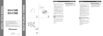
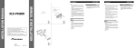
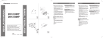
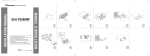
Fig. 1
Abb. 1
Afb. 1
2
1
182
53
3
4
Fig. 2
Abb. 2
Afb. 2
Fig. 3
Abb. 3
Afb. 3
Before finally installing the unit, connect the
wiring temporarily, making sure it is all connected up properly, and the unit and the system work
properly.
Use only the parts included with the unit to
ensure proper installation. The use of unauthorized parts can cause malfunctions.
Consult with your nearest dealer if installation
requires the drilling of holes or other modifications of the vehicle.
Install the unit where it does not get in the driver’s way and cannot injure the passenger if there
is a sudden stop, like an emergency stop.
If installation angle exceeds 30° from horizontal,
the unit might not give its optimum performance.
(Fig. 1)
Installation with the rubber bush
(Fig. 2)
1. Dashboard
2. Holder
After inserting the holder into the dashboard,
then select the appropriate tabs according to the
thickness of the dashboard material and bend
them.
(Install as firmly as possible using the top and the
bottom tabs. To secure, bend the tabs 90
degrees.)
3. Rubber bush
4. Screw
<ENGLISH>
Removing the Unit (Fig. 3)
5. Insert the supplied extraction keys into the unit,
as shown in the figure, until they click into place.
Keeping the keys pressed against the sides of the
unit, pull the unit out.
Instalación
Nota:
•
•
•
•
•
Antes de finalmente instalar la unidad, conecte el
cableado temporalmente y asegúrese de que todo
esté conectado correctamente y que la unidad y
el sistema funcionan debidamente.
Utilice sólo las piezas que se incluyen con esta
unidad para asegurar la instalación adecuada. El
uso de piezas no autorizadas podría causar fallos
de funcionamiento.
Consulte con su distribuidor si la instalación
requiere del taladro de orificios u otras modificaciones del vehículo.
Instale la unidad donde no alcance el espacio del
conductor, y donde no pueda dañar a los
pasajeros si sucediera un paro repentino, como
una detención de emergencia.
Si el ángulo de la instalación excede los 30° del
lado horizontal, la unidad podría no brindar su
óptimo funcionamiento. (Fig. 1)
Instalación con tope de goma
(Fig. 2)
1. Tablero de instrumentos
2. Soporte
Después de insertar el soporte en la tabla de
mandos, luego seleccione las orejetas apropiadas
según el grosor del material de la tabla de mandos y dóblelos.
(Instale lo más firme posible usando las lengüetas
superior e inferior. Para fijar, doble las lengüetas
90 grados.)
3. Tope de goma
4. Tornillo
<ESPAÑOL>
Quitado de la unidad (Fig. 3)
5. Inserte las herramientas de extracción suministradas en la unidad, como se indica en la figura,
hasta que se enganchen en su positión.
Tire de la unidad mientras mantiene las herramientas presionadas contra los lados de la
unidad.
Einbau
Hinweis:
•
•
•
•
•
Schließen Sie vor dem Einbau die Leitungen
vorübergehend an und stellen Sie sicher, das alles
richtig angeschlossen ist und das Gerät und das
System einwandfrei arbeiten.
Um einwandfreien Einbau zu gewährleisten,
sollten nur die mit dem Gerät mitgelieferten Teile
verwendet werden. Bei Verwendung von NichtOriginalteilen kann es zu Funktionsstörungen
kommen.
Wenden Sie sich an Ihren Fachhänlder, wenn
zum Einbau des Geräts Löcher gebohrt oder
andere Veränderungen an Ihrem Auto vorgenommen werden müssen.
Bauen Sie das Gerät an einer Stelle ein, wo es
den Fahrer nicht behindert und den Beifahrer bei
plötzlichem Bremsen nicht verletzen an.
Wenn der Einbauwinkel mehr als 30º von der
Horizontalen abweicht, kann es sein, daß das
Gerät nicht optimal arbeitet. (Abb.1)
Einbau mit der Gummibuchse
(Abb. 2)
1. Armaturenbrett
2. Halter
Den Halter in das Armaturenbrett einsetzen, dann
die der Dicke des Armaturenbretts entsprechenden Zungen auswählen und diese biegen.
(Mit Hilfe der Ansätze, oben und unten, so fest
wie möglich einsetzen. Zur Sicherung werden die
Ansätze 90 Grad gebogen.)
3. Gummibuchse
4. Schraube
<DEUTSCH>
Entnahme des Gerätes (Abb. 3)
5. Die mitgelieferten Ausziehschlüssel wie in der
Abbildung gezeigt bis zur Einrastposition in das
Gerät einsetzen. Die Schlüssel gegen die Seiten
des Geräts drücken und das Gerät herausziehen.
Installation
Remarque:
•
•
•
•
•
Avant de finaliser l’installation de l’appareil, connecter temporairement le câblage en s’assurant
que tout est correctement connecté et que l’appareil et le système fonctionnement correctement.
Pour obtenir une bonne installation, n’utiliser que
les pièces de l’appareil. L’utilisation de pièces
non prévues risque de causer un mauvais fonctionnement.
Consulter le concessionnaire le plus proche si
l’installation nécessite le percement de trous ou
toute autre modification du véhicule.
Installer l’appareil à un endroit où il ne gêne pas
le conducteur et où il ne peut pas blesser les passagers en cas d’arrêt brusque, comme pendant un
arrêt d’urgence.
L’angle de l’installation, ne doit pas dépasser 30°
par rapport à l’horizontale, faute de quoi l’unité ne
fournira pas ses performances optimales. (Fig. 1)
Installation avec une bague en
caoutchouc (Fig. 2)
1. Tableau de bord
2. Support
Après avoir introduit le support dans le tableau
de bord, sélectíonnez les languettes appropriées
en fonction de l’épaisseur du matériau du tableau
de bord et courbez-les.
(Assurez le maintien aussi solidement que possible en utilisant les languettes inférieures et
supérieures. Cela fait, courbez les languettes de
90 degrés.)
3. Bague en caoutchouc
4. Vis
<FRANÇAIS>
Dépose de l’únite (Fig. 3)
5. Insérer les clés d’extraction fournis dans l’unité,
comme indiqué dans la figure, jusqu’à ce qu’elles
s’enclenchent en position. En maintenant ces clés
pressées contre les côtés de l’unité, retirer l’unité.
Installazione
Nota:
•
•
•
•
•
Prima di installare definitivamente l’apparecchio,
collegare i fili temporaneamente e accertarsi che
tutti i collegamenti siano corretti e che l’apparecchio e il sistema funzionino correttamente.
Per un’installazione appropriata, usare soltanto i
pezzi in dotazione all’apparecchio. L’uso di pezzi
non autorizzati può causare problemi di
funzionamento.
Rivolgersi al più vicino rivenditore se l’installazione richiede la trapanatura di fori o altre
modifiche del veicolo.
Installare l’apparecchio in un punto in cui esso
non intralci le manovre del conducente e in cui
non possa provocare lesioni ai passeggeri nel
caso dell’arresto improvviso del veicolo, come
nel caso di una frenata d’emergenza.
Se l’angolo di installazione supera i 30° rispetto
alla posizione orizzontale, l’apparecchio potrebbe
non fornire prestazioni ottimali. (Fig. 1)
Installazione con la boccola di
gomma (Fig. 2)
1. Cruscotto
2. Supporto
Dopo aver inserito il supporto nel cruscotto,
selezionare le linguette appropriate a seconda
dello spessore del materiale del cruscotto e piegarle.
(Installare quanto più saldamente possibile servendosi delle linguette superiore e inferiore. Per
fissare, piegare le linguette a 90 gradi.)
3. Boccola di gomma
4. Vite
<ITALIANO>
Estrazione dell’unità (Fig. 3)
5. Inserire le chiavette di estrazione in dotazione
nell’apparecchio, come mostrato nella figura,
finché non scattano in posizione. Tenendo le
chiavette premute contro i lati dell’apparecchio,
estrarre l’apparecchio.
Installeren
Opmerking:
•
•
•
•
•
Voor u het apparaat definitief installeert, is het
raadzaam eerst alle aansluitingen tijdelijk te
maken om te kontroleren of alles naar behoren
funktioneert, zodat u later niet voor verrassingen
komt te staan.
Gebruik voor het installeren uitsluitend de bij het
apparaat geleverde onderdelen. Toepassing van
andere dan de goedgekeurde onderdelen kan leiden tot storing in de werking van het apparaat.
Raadpleeg uw dichtstbijzijnde dealer als het voor
het installeren van het apparaat nodig blijkt gaten
te boren, of andere wijzigingen aan te brengen
aan de auto.
Installeer het apparaat op een plaats waar het de
bestuurder niet in de weg kan zitten en waar het
ook bij een noodstop e.d. geen gevaar voor de
inzittenden kan opleveren.
Als u het apparaat onder een al te steile hoek
installeert, d.w.z. meer dan 30° uit het horizontale vlak, zal het niet naar behoren kunnen
werken. (Afb. 1)
Installatie met de rubber mof
(Afb. 2)
1. Dashboard
2. Houder
Nadat u de houder in het dashboard hebt
geplaatst, kiest u de juiste lipjes voor de dikte
van het dashboard-materiaal en buigt u deze om.
(Plaats zo stevig als mogelijk met gebruik van de
boven- en onderlipjes. Buig de lipjes 90 graden
om te vergrendelen.)
3. Rubber mof
4. Schroef
<NEDERLANDS>
Verwijderen van het apparaat
(Afb. 3)
5. Steek de bijgeleverde verwijdersleutels in het
apparaat, zoals in de afbeelding aangegeven, tot
ze op hun plaats vastklikken. Houd de sleutels
tegen de zijkanten van het apparaat aangedrukt
en trek het apparaat naar buiten.
Connecting the Units
7
6
9
8
6.Yellow
To terminal always supplied with power
regardless of ignition switch position.
9.Red
Accessory (or Back-up)
8.Red
To electric terminal controlled by ignition
switch (12 V DC) ON/OFF.
10.Black (ground)
To vehicle (metal) body.
11.ISO connector
Note:
In some vehicles, the ISO connector may be
divided into two. If this is the case, be sure to
connect to both connectors.
13.Blue/white
To Auto-antenna relay control terminal.
(Max. 300 mA 12 V DC.)
14. Blue/white
The pin position of the ISO connector
will differ according to the type of
vehicle. Connect 13 and 14 when Pin 5 is
an antenna control type. In another type
of vehicle, never connect 13 and 14.
12.Speaker leads
White: Front left +
White/black: Front left ≠
Gray: Front right +
Gray/black: Front right ≠
Green: Rear left +
Green/black: Rear left ≠
Violet: Rear right +
Violet/black: Rear right ≠
Fig. 4
Abb. 4
Afb. 4
ACC position
F
O
STAR
7.Yellow
Back-up (or Accessory)
O
N
5.Cap
ACC
STAR
3.Connect leads of the same
color to each other.
F
N
4. Note:
Depending on the kind of vehicle, the
function of 7 and 9 may be different.
If this is the case, be sure to connect
6 to 9 and 7 to 8.
When the power cord of the other
product is connected to terminal 5,
check the function of the terminal 5
(Back up or Accessory) beforehand.
OF
5
•
OF
2.Antenna jack
•
When this product’s source is switched ON, a
control signal is output through the blue/white
lead. Connect to the car’s Auto-antenna relay
control terminal. (Max. 300 mA 12 V DC.) If the
car features a glass antenna, connect to the antenna booster power supply terminal.
To avoid short-circuiting, cover the disconnected
lead with insulating tape. Especially, insulate the
unused speaker leads without fail. There is a possibility of short-circuiting if the leads are not
insulated.
If this unit is installed in a vehicle that does not
have an ACC (accessory) position on the ignition
switch, the red lead of the unit should be connected to a terminal coupled with ignition switch
ON/OFF operations. If this is not done, the vehicle battery may be drained when you are away
from the vehicle for several hours.
T
15.Fuse
•
T
1.This Product
Note:
• This unit is for vehicles with a 12-volt battery
and negative grounding. Before installing it in a
recreational vehicle, truck, or bus, check the battery voltage.
• To avoid shorts in the electrical system, be sure
to disconnect the ≠ battery cable before beginning installation.
• Secure the wiring with cable clamps or adhesive
tape. To protect the wiring, wrap adhesive tape
around them where they lie against metal parts.
• Route and secure all wiring so it cannot touch
any moving parts, such as the gear shift, handbrake and seat rails. Do not route wiring in
places that get hot, such as near the heater outlet.
If the insulation of the wiring melts or gets torn,
there is a danger of the wiring short-circuiting to
the vehicle body.
• Don’t pass the yellow lead through a hole into
the engine compartment to connect to the battery.
This will damage the lead insulation and cause a
very dangerous short.
• Do not shorten any leads. If you do, the protection circuit may fail to work when it should.
• Never feed power to other equipment by cutting
the insulation of the power supply lead of the
unit and tapping into the lead. The current capacity of the lead will be exceeded, causing overheating.
• When replacing fuse, be sure to use only fuse of
the rating prescribed on this unit.
• Since a unique BPTL circuit is employed, never
wire so the speaker leads are directly grounded or
the left and right ≠ speaker leads are common.
• Speakers connected to this unit must be highpower types with minimum rating of 40 W and
impedance of 4 to 8 ohms. Connecting speakers
with output and/or impedance values other than
those noted here may result in the speakers catching fire, emitting smoke or becoming damaged.
<ENGLISH>
No ACC position
•
The black lead is ground. Please ground this lead
separately from the ground of high-current products such as power amps.
If you ground the products together and the
ground becomes detached, there is a risk of damage to the products or fire.
•
Cords for this product and those for other products may be different colors even if they have the
same function. When connecting this product to
another product, refer to the supplied Installation
manuals of both products and connect cords that
have the same function.
Connection Diagram (Fig.4)
1.
2.
3.
4.
This product
Antenna jack
Connect leads of the same color to each other.
Note:
Depending on the kind of vehicle, the function of
7 and 9 may be different. If this is the case, be
sure to connect 6 to 9 and 7 to 8.
When the power cord of the other product is connected to terminal 5, check the function of the
terminal 5 (Back up or Accessory) beforehand.
5. Cap
6. Yellow
To terminal always supplied with power regardless of ignition switch position.
7. Yellow
Back-up (or Accessory)
8. Red
To electric terminal controlled by ignition switch
(12 V DC) ON/OFF.
9. Red
Accessory (or Back-up)
10. Black (ground)
To vehicle (metal) body.
11. ISO connector
Note:
In some vehicles, the ISO connector may be
divided into two. If this is the case, be sure to
connect to both connectors.
12. Speaker leads
White: Front left +
White/black: Front left ≠
Gray: Front right +
Gray/black: Front right ≠
Green: Rear left +
Green/black: Rear left ≠
Violet: Rear right +
Violet/black: Rear right ≠
13. Blue/white
To Auto-antenna relay control terminal.
(Max. 300 mA 12 V DC.)
14. Blue/white
The pin position of the ISO connector will differ according to the type of vehicle. Connect
13 and 14 when Pin 5 is an antenna control
type. In another type of vehicle, never connect
13 and 14.
15. Fuse
Conexión de las unidades
<ESPAÑOL>
Nota:
•
•
5
7
6
9
8
4. Note:
Depending on the kind of vehicle, the
function of 7 and 9 may be different.
If this is the case, be sure to connect
6 to 9 and 7 to 8.
When the power cord of the other
product is connected to terminal 5,
check the function of the terminal 5
(Back up or Accessory) beforehand.
•
9.Red
Accessory (or Back-up)
8.Red
To electric terminal controlled by ignition
switch (12 V DC) ON/OFF.
10.Black (ground)
To vehicle (metal) body.
11.ISO connector
Note:
In some vehicles, the ISO connector may be
divided into two. If this is the case, be sure to
connect to both connectors.
13.Blue/white
To Auto-antenna relay control terminal.
(Max. 300 mA 12 V DC.)
14. Blue/white
The pin position of the ISO connector
will differ according to the type of
vehicle. Connect 13 and 14 when Pin 5 is
an antenna control type. In another type
of vehicle, never connect 13 and 14.
12.Speaker leads
White: Front left +
White/black: Front left ≠
Gray: Front right +
Gray/black: Front right ≠
Green: Rear left +
Green/black: Rear left ≠
Violet: Rear right +
Violet/black: Rear right ≠
•
•
•
•
Fig. 4
Abb. 4
Afb. 4
O
Posición ACC
F
O
STAR
7.Yellow
Back-up (or Accessory)
ACC
N
•
6.Yellow
To terminal always supplied with power
regardless of ignition switch position.
F
STAR
5.Cap
•
N
3.Connect leads of the same
color to each other.
•
OF
15.Fuse
2.Antenna jack
Cuando se conecta la fuente de este producto, una
señal de control se emite a través del conductor
azul/blanco. Conecte al terminal de controle de relé
de antena automática del vehículo. (Máx. 300 mA
12 V CC.) Si el vehículo tiene una antena en
vidrio, conecte al terminal de suministro de energía
de la antena.
Para evitar cortocircuitos, cubra el conductor
desconectado con cinta aislada. Especialmente,
aísle los conductores de altavoz no usados. Hay la
posibilidad de cortocircuito si no se aíslan los
conductores.
Si se instala esta unidad en un vehículo que no
tiene una posición ACC (accesorio) en el interruptor de encendido, el conductor rojo de la
unidad deberá conectarse al terminal conectado
con las operaciones del interruptor de encendido
ON/OFF. Si no se hace esto, la batería del
vehículo podría drenarse cuando usted esté lejos
del vehículo por varias horas.
OF
•
•
T
1.This Product
Esta unidad es para vehículos con batería de 12
voltios y con conexión a tierra. Antes de instalar
la unidad en un vehículo recreativo, camioneta, o
autobús, revise el voltaje de la batería.
Para evitar cortocircuitos en el sistema eléctrico,
asegúrese de desconectar el cable de la batería ≠
antes de comenzar con la instalación.
Asegure el cableado con abrazaderas de cables o
con cinta adhesiva. Para proteger el cableado,
envuélvalo con cinta adhesiva donde éstos se
apoyan sobre las piezas de metal.
Coloque y asegure todo el cableado de tal manera
que no toque las piezas en movimiento, tal como
la palanca de cambio de velocidades, el freno de
mano, y los pasamanos de los asientos. No
coloque el cableado en lugares que se calientan,
tal como cerca de la salida de un calefactor. Si el
material aislante del cableado se derritiera o se
gastara, habrá el peligro de un cortocircuito del
cableado a la carrocería del vehículo.
No pase el conductor amarillo a través de un orificio en el compartimiento del motor para conectar a la batería. Esto dañará el material aislante
del conductor y causará un cortocircuito peligroso.
No acorte ningún conductor. Si lo hiciera, la protección del circuito podría fallar al funcionar
cuando debería.
Nunca alimente energía a otros equipos cortando
el aislamiento del conductor de alimentación provista de la unidad y haciendo un empalme con el
conductor. La capacidad de corriente del conductor se excederá, causando el recalentamiento.
Cuando reemplace el fusible, asegúrese de utilizar solamente un fusible del régimen nominal
prescrito en esta unidad.
Ya que se emplea un circuito único BPTL, nunca
coloque los cables de manera que los conductores del altavoz estén directamente en conexión
a tierra o que el altavoz izquierdo y derecho ≠
sean comunes.
Los altavoces conectados a esta unidad deberán ser
del tipo de alta potencia, teniendo un régimen
mínimo de 40 W y una impedancia de 4 a 8
ohmios. La conexión de altavoces con valores de
impedancia y/o de salida diferentes a los anotados
aquí podrían causar fuego, emisión de humo o
daños a los altavoces.
T
•
No en la posición ACC
•
El conductor negro es la masa. Conecte a masa
este conductor separadamente desde la masa de
los productos de alta corriente tal como los
amplificadores de potencia.
Si conecta juntos a masa los productos y la masa
se desconecta, se crea el riesgo de daños a los
productos o de incendios.
•
Los cables para este producto y aquéllas para
otros productos pueden ser de colores diferentes
aun si tienen la misma fución. Cuando se
conecta este producto a otro, refiérase a los
manuales de instalación de ambos productos y
conecte los cables que tienen la misma función.
Diagrama de conexión (Fig. 4)
1. Este producto
2. Jack para antena
3. Conecte los conductores del mismo color uno a
otro.
4. Nota:
Dependiendo en el tipo del vehículo, la función
de 7 y 9 puede ser diferente. Si éste es el caso,
asegúrese de conectar 6 a 9 y 7 a 8.
Cuando el cable de alimentación del otro aparato
esté conectado al terminal 5, compruebe de antemano la función del terminal 5 (Conservación o
Accesorio).
5. Tapa
6. Amarillo
Al terminal con suministro constante de electricidad, independientemente de la posición del
interruptor de encendido.
7. Amarillo
Reserva (o Accesorio)
8. Rojo
Al terminal de energía eléctrica controlado por el
interruptor de encendido del vehículo (12 V CC)
ON/OFF.
9. Rojo
Accesorio (o Reserva)
10. Negro (masa)
A la carrocería del veículo (parte metálica).
11. Conector ISO
Nota:
En algunos vehículos, el conector ISO puede
estar dividido en dos partes. Si éste es el caso,
asegúrese de conectar a ambos conectores.
12. Conductores de altavoz
Blanco: Izquierdo delantero +
Blanco/negro: Izquierdo delantero ≠
Gris: Derecho delantero +
Gris/negro: Derecho delantero ≠
Verde: Izquierdo trasero +
Verde/negro: Izquierdo trasero ≠
Violeta: Derecho trasero +
Violeta/negro: Derecho trasero ≠
13. Azul/blanco
Al terminal de control del relé de antena
automática. (Máx. 300 mA 12 V CC.)
14. Azul/blanco
La posición de los pinos del conector ISO
difiere de acuerdo al tipo de vehículo. Conecte
13 y 14 cuando el pino 5 es un tipo de control
de antena. En otros tipos de vehículo, nunca
conecte 13 y 14.
15. Fusible
Anschließen der Geräte
OF
Kabel dieses Produkts und die anderer Produkte
können unterschiedliche Farben haben, auch
wenn sie die gleichen Funktionen haben. Beim
Anschluß dieses Produkts an ein anderes
Produkt unter Bezugnahme auf die mit beiden
Produkten mitgelieferten
Installationsanleitungen die Kabel mit derselben
Funktion verbinden.
•
•
•
15. Sicherung
•
•
•
•
•
•
•
•
Quand la source de ce produit est positionnée sur
ON, un signal de commande est sorti par le fil
bleu/blanc. Connectez-le à la borne de commande du relais d’antenne motorisée (Max. 300
mA, 12 V CC). Si la voiture utilise une antenne
de vitre, connectez-le à la prise d’alimentation de
l’amplificateur d’antenne.
Pour éviter les courts-circuits, recouvrez les fils
déconnectés par du ruban isolant. En particulier,
n’oubliez pas d’isoler les fils d’enceintes. Un
court-circuit peut se produire si les fils ne sont
pas isolés.
Si cette unité est installée dans un véhicule dont
le contacteur d’allumage n’a pas de position ACC
(accessoire), le fil rouge de l’unité doit être connecté à une borne couplée aux opérations de
marche/arrêt du contacteur d’allumage. Sinon, la
batterie du véhicule peut se décharger lorsque le
véhicule n’est pas utilisé pendant plusieurs
heures.
F
ACC
O
Position ACC
OF
14. Blau/weiß
Die Pin-Position des ISO-Anschlusses hängt
vom Fahrzeugtyp ab. 13 und 14 anschließen,
wenn es sich bei Pin 5 um einen
Antennensteuerungstyp handelt. Bei einem
anderen Fahrzeugtyp 13 und 14 niemals
anschließen.
•
OF
13. Blau/weiß
An Relais-Steuerungs-anschluß für die automatische Antenne. (Max. 300 mA, 12 V
Gleichspannung.)
Cet appareil est destiné aux véhicules avec une
batterie de 12 V, avec pôle négatif à la masse.
Avant de l’installer dans un véhicule de loisir, un
camion ou un car, vérifier la tension de la batterie.
Afin d’éviter tout risque de court-circuit,
débrancher le câble de la borne négative ≠ de la
batterie avant de commencer la pose.
Fixer les câbles au moyen de colliers ou de
morceaux de ruban adhésif. Pour protéger le
câblage, enrouler la bande adhésive autour des
câbles à l’endroit où ceux-ci sont placés contre
les parties métalliques.
Acheminer et fixer tout le câblage de telle sorte
qu’il ne touche pas les pièces mobiles, comme le
levier de changement de vitesse, le frein à main
et les rails des sièges. Ne pas acheminer les
câbles dans des endroits qui peuvent devenir
chauds, comme près de la sortie de radiateur. Si
l’isolation des câbles fond ou est se déchire, il
existe un danger de court-circuit des câbles avec
la carrosserie du véhicule.
Ne pas faire passer le conducteur jaune dans le
compartiment moteur par un trou pour le connecter avec la batterie. Cela pourrait endommager sa gaine d’isolation et provoquer un grave
court-circuit.
Ne pas court-circuiter les conducteurs. Dans le
cas contraire, le circuit de protection risque de ne
pas fonctionner.
Ne jamais alimenter un autre appareil par un
branchement sur le câble d’alimentation de
celui-ci. Le courant qui circulerait dans ce conducteur pourrait dépasser la capacité du conducteur et entraîner une élévation anormale de température.
En cas de remplacement du fusible, n’utilisez
qu'un fusible identique à celui prescrit sur
l’appareil.
Un circuit BPTL unique étant employé,
n’effectuez jamais le câblage de sorte que les fils
de haut-parleurs soient directement mis à la
masse ou que les fils de haut-parleurs ≠ gauche
et droit soient communs.
Les haut-parleurs connectés à cet appareil
doivent être tels qu’ils puissent supporter une
puissance de 40 W, et que leur impédance soit
comprise entre 4 et 8 Ohms. L’utilisation de
haut-parleurs dont la puissance admissible ou
l’impédance seraient différentes des valeurs
indiquées ici, pourrait provoquer leur inflammation, avec émission de fumée, ou à tout le moins
leur endommagement.
F
O
STAR
Das schwarze Kabel ist das Erdungskabel. Dieses
Kabel ist getrennt von der Erde von HochstromGeräten, wie z.B. Leistungsverstärkern, zu erden.
Falls die Geräte zusammen geerdet werden, und
die Erdungsstelle abgetrennt wird, besteht die
Gefahr einer Beschädigung der Geräte oder eines
Brands.
•
N
•
Keine ACC-Position
1. Dieses Produkt
2. Antennenbuchse
3. Verbinden Sie Leitungen derselben Farbe
miteinander.
4. Hinweis:
Je nach Art des Fahrzeugs können Funktionen 7
und 9 verschieden sein. In diesem Fall ist darauf
zu achten, 6 mit 9 und 7 mit 8 zu verbinden.
Wenn das Netzkabel des anderen Geräts mit
Klemme 5 verbunden ist, muß vorher die
Funktion der Klemme 5 (Reserve oder Zubehör)
überprüft werden.
5. Kappe
6. Gelb
An eine Stromversorgung anschließen, die unabhängig vom Zündschloß immer Strom führt.
7. Gelb
Reserve (oder Zubehör)
8. Rot
An eine Stromversorgung anschließen, (12 V
Gleichspannung), die mit dem Zündschloß einund ausgeschaltet wird.
9. Rot
Zubehör (oder Reserve)
10. Schwarz (Erdung)
An die Karosserie (Metallteil) anschließen.
11. ISO-Anschluß
Hinweis:
Bei einigen Fahrzeugen kann der ISOSteckverbinder in zwei Hälften geteilt sein. In
diesem Fall den Anschluß unbedingt an beiden
Steckverbindern vornehmen.
12. Lautsprecherkabel
Weiß: Vorne links +
Weiß/Schwarz: Vorne links ≠
Grau: Vorne rechts +
Grau/Schwarz: Vorne rechts ≠
Grün: Hinten links +
Grün/schwarz: Hinten links ≠
Violett: Hinten rechts +
Violett/schwarz: Hinten rechts ≠
Remarque:
STAR
•
O
Anschlußzeichnung (Abb. 4)
N
•
ACC-Position
F
STAR
•
O
N
•
ACC
STAR
•
F
N
•
OF
•
•
T
•
•
Wenn die Programmquelle dieses Produkts
eingeschaltet wird, wird ein Steuersignal über
das blau/weiße Kabel ausgegeben. An die
Auto-Antennenrelais-Steuerung des Wagens
anschließen. (Max. 300 mA, 12 V
Gleichspannung.) Wenn der Wagen mit einer
Fensterantenne ausgestattet ist, an die
Antennenverstärker-Stromversorgungsklemme
anschließen.
Um einen Kurzschluß zu vermeiden, abgetrennte
Kabel mit Isolierband umwickeln. Unbenutzte
Lautsprecherkabel müssen unbedingt isoliert
werden. Wenn die Kabel nicht isoliert werden,
besteht Kurzschlußgefahr.
Wenn dieses Gerät in einem Auto eingebaut wird,
das auf dem Zündschalter keine ACC (Zubehör)Position hat, sollte die rote Leitung des Geräts an
eine Klemme angeschlossen werden, die mit der
ON/OFF-Operation des Zündschalters gekoppelt
ist. Andernfalls kann die Autobatterie entleert
werden, wenn Sie mehrere Stunden von dem
Fahrzeug weg sind.
T
•
•
T
•
Dieses Gerät ist für Fahrzeuge mit 12-V-Batterie
und negativer Erdung (Minuspol an Masse) ausgelegt. Prüfen Sie vor dem Einbau in ein
Wohnmobil, einen Lastwagen oder Bus die
Batteriespannung.
Um Kurzschlüsse im elektrischen Systen zu verhindern, ist unbedingt vor dem Einbau das
Minus-Batteriekabel ≠ abzutrennen.
Sichern Sie die Leitungen mit Kabelklemmen
oder Klebeband. Zum Schutz der Leitungen
sollten sie an den Stellen, wo sie Metallteile
berühren, mit Klebeband umwickelt werden.
Verlegen und sichern Sie alle Leitungen so, daß
sie keine beweglichen Teile wie die
Gangschaltung, die Handbremse und
Sitzschienen berühren. Die Leitungen dürfen
nicht an Stellen entlanggeführt werden, die heiß
werden, z.B. an einer Heizungsauslaßöffnung.
Wenn die Isolierung einer Leitung schmilzt oder
aufreißt, besteht die Gefahr eines Kurzschlusses
mit der Karosserie.
Führen Sie die gelbe Leitung nicht durch ein
Loch in den Motorraum zum Anschluß an die
Batterie. Dadurch wird die Isolierung der Leitung
beschädigt, was zu einem sehr gefährlichen
Kurzschluß führen kann.
Verkürzen Sie keine Leitungen. In diesem Fall
kann es vorkommen, daß die Schutzschaltung
nicht arbeitet, wenn sie gebraucht wird.
Führen Sie niemals anderen Geräten Strom zu,
indem Sie die Isolierung der
Stromversorgungsleitung dieses Geräts durchschneiden und davon Strom abzapfen. Dadurch
wird die Strombelastbarkeit der Leitung überschritten, was zu Überhitzung führt.
Als Ersatzsicherungen dürfen nur solche mit dem
vorgeschriebenen Nennwert verwendet werden.
Da ein einzigartiger BPTL-Schaltkreis verwendet
wird, dürfen die Lautsprecherleitungen niemals
direkt geerdet oder die Minusleitungen ≠ des
rechten und linken Kanals gemeinsam sein.
Lautsprecher, die an dieses Gerät angeschlossen
werden, müssen eine minimale Nennleistung von
40 W und eine Impedanz zwischen 4 und 8 Ohm
haben. Falls Lautsprecher mit anderen Leistungsund/oder Impedanzwerten angeschlossen werden,
können die Lautsprecher in Brand geraten, Rauch
entwickeln und beschädigt werden.
<FRANÇAIS>
T
Hinweis:
•
Connexion des appareils
<DEUTSCH>
Aucune position ACC
•
Le conducteur noir est le fil de masse. Veillez à
relier ce conducteur à une masse qui ne soit pas
la masse d’un appareil gros consommateur
d’énergie tel qu’un amplificateur de puissance.
En effet, si vous utilisez la même masse pour
plusieurs appareils et si ces masses sont
supprimées par un défaut de contact,
l’endommagement de l’appareil, voire un
incendie sont possibles.
•
Les câbles de ce produit et ceux d’autres produits peuvent fort bien ne pas être de la même
couleur bien que remplissant la même fonction.
Pour relier ce produit à un autre produit, utilisez
le manuel d’installation de chacun et effectuez
les raccordements en ne tenant compte que de la
fonction de chaque câble.
Schéma de connexion (Fig. 4)
1. Ce produit
2. Jack d’antenne
3. Reliez ensemble les conducteurs de même
couleur.
4. Remarque:
Selon le type de véhicule, le rôle de 7 et 9 peut
différer. Si cela est le cas, veillez à relier 6 à 9 et
7 à 8.
Avant de relier le cordon d’alimentation de
l’autre appareil à la borne 5, vérifiez le rôle
(Secours ou Accessoire) de cette borne.
5. Cache
6. Jaune
Vers une borne alimentée en permanence
indépencamment de la clé de contact.
7. Jaune
Secours (ou Accessoire)
8. Rouge
Vers une borne dont l’alimentation est commandée par la clé de contact (12 V CC).
9. Rouge
Accessoire (ou Secours)
10. Noir (masse)
Fil de masse vers un élément en métal apparent
de la voiture.
11. Connecteur ISO
Remarque:
Sur certains véhicules, le connecteur ISO peut
comporter deux parties. En ce cas, veillez à relier
ces deux parties.
12. Câbles de haut-parleurs
Blanc: avant gauche +
Blanc/noir: avant gauche ≠
Gris: avant droite +
Gris/noir: avant droite ≠
Vert: arrière gauche +
Vert/noir: arrière gauche ≠
Violet: arrière droite +
Violet/noir: arrière droite ≠
13. Bleu/blanc
Vers la borne de commande de l’antenne
motorisée. (Max. 300 mA, 12 V CC)
14. Bleu/blanc
La disposition des broches du connecteur ISO
diffère en fonction du type de véhicule.
Connectez 13 et 14 quand la broche 5 est la
commande d’antenne. Sinon, ne connectez
jamais les broches 13 et 14.
15. Fusible
Collegamento degli apparecchio
<ITALIANO>
•
Il cavo nero è quello di messa a terra. Mettere a
terra questo cavo separatamente da quello di
messa a terra di apparecchi funzionanti con
corrente a tensioni elevate, quali gli amplificatori
di potenza.
Se gli apparecchi si trovano messi a terra
insieme, in caso di distacco della messa a terra,
possono verificarsi incendi, o prodursi danni agli
apparecchi.
I cavi per questo apparecchio e quelli per altri
apparecchi possono avere colori diversi, pur svolgendo la stessa funzione. Per il collegamento di
questo apparecchio ad un’altro, vedere i manuali
di installazione di entrambi gli apparecchi, e
provvedere al collegamento dei cavi aventi la
stessa funzione.
•
•
15. Fusibile
•
•
•
•
•
•
•
•
•
Wanneer de signaalbron van dit product aan
(ON) staat, wordt er een controlesignaal geproduceerd via de blauw/witte draad. Sluit deze aan
op de bedieningsaansluiting van het auto-antenne
relais van de auto zelf. (Max. 300 mA 12 Volt
gelijkstroom) Als de auto voorzien is van een
glas-antenne, dient u de aansluiting te maken op
de aansluiting van de stroomvoorziening van de
antennebooster.
Om kortsluiting te voorkomen dient u de losgekoppelde draad af te dekken met isolatieband.
Vergeet vooral niet de ongebruikte luidsprekerdraden te isoleren. Als de draden niet geïsoleerd
zijn, bestaat er het gevaar van kortsluiting.
Bij inbouw van dit apparaat in een auto waarvan
het kontaktslot geen “ACC” stand heeft, dient u
de rode stroomdraad van dit apparaat aan te
sluiten op een aansluitpunt waarvan de stroom
wordt in- en uitgeschakeld door ON/OFF zetten
van het kontaktsleuteltje. Als u deze stroomdraad
aansluit op een punt dat altijd stroom krijgt, kan
de accu leegraken als u de auto enkele uren
ongebruikt laat.
F
ACC
O
ACC stand
OF
14. Blu/bianco
La posizione dei poli del connettore ISO
differisce in relazione al tipo di veicolo. Se il
polo 5 è del tipo per il comando dell'antenna,
collegare 13 e 14. Nei veicoli di altri tipi non
collegare mai 13 e 14.
•
OF
13. Blu/bianco
Al terminale dell’antenna elettrica.
(massimo 300 mA, con corrente continua a 12 V.)
Dit apparaat is bestemd voor inbouw in
voertuigen met een negatief geaarde 12-volts
accu. Alvorens u het installeert in een auto, bus,
vrachtwagen of ander voer- of vaartuig, dient u
eerst te kontroleren of de accuspanning de juiste
is.
Om kortsluiting te vermijden, dient u vooral voor
het installeren de negatieve ≠ accukabel los te
maken.
Houd de bedrading op zijn plaats met kabelklemmen of met isolatieband. Wikkel ter bescherming
ook isolatieband om de bedrading waar deze de
metalen oppervlakken van de auto raakt.
Leid de bedrading altijd zo dat deze niet in aanraking kan komen met bewegende onderdelen
zoals de versnellingspook, de handrem en de
geleiderails van de stoelen. Zet de bedrading stevig vast en vermijd ook plaatsen die warm worden, zoals bij een uitblaasopening van de
autoverwarming. Als de isolatie smelt of door
beweging doorslijt, zou er kortsluiting kunnen
onstaan.
Leid de gele draad niet door het brandschot naar
de motorruimte voor aansluiting op de accu.
Hierbij is de kans groot op beschadiging van de
isolatie en zeer gevaarlijke kortsluiting.
Maak de bedrading niet korter. Bij inkorten van
de bedrading kan het beveiligingscircuit niet in
werking treden wanneer dat nodig is.
Tap geen stroom af van de bedrading door een
stukje isolatie te verwijderen en een andere draad
aan de kerndraad te verbinden. Hierdoor kan de
maximale stroomcapaciteit van de draad overschreden worden, met als gevolg oververhitting.
Gebruik voor het vervangen van de zekering uitsluitend een zekering van het op dit toestel
gespecificeerde vermogen.
Aangezien er gebruik is gemaakt van een uniek
BPTL circuit, mag u de luidsprekersnoeren nooit
rechtstreeks met de aarde verbinden en mag u
ook niet de negatieve ≠ luidsprekerdraden
gemeenschappelijk aansluiten.
Sluit op dit apparaat luidsprekers aan die een
hoog ingangsvermogen kunnen verwerken, van
nominaal tenminste 40 W, met een impedantie
van 4 tot 8 Ohm. Sluit u luidsprekers aan die niet
aan deze eisen voldoen, dan bestaat er de kans
dat de luidsprekers in brand vliegen, beginnen te
roken of anderszins beschadigd raken.
F
O
STAR
•
Questo apparecchio
Terminal per antenna
Collegare fra loro cavi di uguale colore.
Nota:
Le funzioni di 7 ed 9 possono differire a seconda
del veicolo. In tal caso, collegare 6 a 9 e 7 a 8.
Prima di collegare il cavo di alimentazione al terminal 5 (Energia elettrica di riserva o
Accessoria), controllare che funzioni.
5. Cappuccio
6. Giallo
Al terminale constantemente alimentato,
qualunque sia la posizione della chiave
d’accensione.
7. Giallo
Riserva (o Accessoria)
8. Rosso
Collegare alla chiave d’avviamento ON/OFF
(con corrente continua a 12 V).
9. Rosso
Accessoria (o Riserva)
10. Nero (massa)
Al telaio (parte metallica) dell’automobile.
11. Connettore ISO
Nota:
In alcuni veicoli, il connettore ISO potrebbe
essere diviso in due. In tal caso, non mancare di
connettere ambedue i connettori.
12. Cavi diffusori
Bianco: Anteriore sinistro +
Bianco/nero: Anteriore sinistro ≠
Grigio: Anteriore destro +
Grigio/nero: Anteriore destro ≠
Verde: Posteriore sinistro +
Verde/nero: Posteriore sinistro ≠
Violetto: Posteriore destro +
Violetto/nero: Posteriore destro ≠
•
N
Posizione ACC presente Posizione ACC assente
1.
2.
3.
4.
Opmerking:
STAR
STAR
•
F
O
N
•
STAR
•
O
N
•
F
ACC
Schema di collegamento (Fig. 4)
N
•
OF
•
•
OF
•
•
Attivando la sorgente di questo apparecchio,
attraverso il cavo blu/bianco viene emesso un
segnale di comando. Collegare al terminale di
comando del relais dell’antenna ad alzo automatico (massimo 300 mA, con corrente continua
a 12 V).
Se l’automobile dispone di una antenna a vetro,
collegare il cavo al terminale di alimentazione
del booster dell’antenna.
Per evitare corti circuiti, coprire con nastro
isolante il cavo staccato. In particolare, devono
assolutamente essere ricoperti con nastro isolante
i cavi non usati degli altoparlanti. Se i cavi non
vengono isolati possono verificarsi dei pericolosi
corti circuiti.
Se questo apparecchio viene installato in un veicolo che non possiede una posizione ACC (accessoria) sull’interruttore di accensione, il cavo
rosso dell’apparecchio deve essere collegato ad
un terminale accoppiato con le operazioni di
accensione/spegnimento dell’interruttore di
accensione. Se ciò non viene fatto, la batteria del
veicolo può scaricarsi quando si lascia il veicolo
per alcune ore.
T
•
•
T
•
Questo apparecchio è per veicoli con una batteria
da 12 volt e una messa a massa negativa. Prima
di installarlo in un veicolo sportivo, in un autocarro o in un autobus, controllare la tensione
della batteria.
Per evitare cortocircuiti nell’impianto elettrico,
accertarsi di scollegare il cavo della batteria ≠
prima di iniziare l’installazione.
Fissare i fili con dei fermacavi o del nastro adesivo. Per proteggere i fili, avvolgervi attorno del
nastro adesivo nei punti in cui essi sono a contatto con parti metalliche.
Disporre e fissare tutti i fili in modo tale che essi
non tocchino alcuna parte in movimento, come
l’asta del cambio, il freno a mano e le guide dei
sedili. Non disporre i fili in luoghi esposti al
calore, come nei pressi della bocca di efflusso
dell’impianto di riscaldamento. Se la guaina
isolante dei fili si fonde o si lacera, c’è il pericolo
che i fili possano provocare cortocircuiti alla carrozzeria del veicolo.
Non far passare il cavo giallo attraverso un foro
per inserirlo nel vano motore per collegare la batteria. Questo danneggia la guaina isolante del cavo e
può causare un cortocircuito molto pericoloso.
Non accorciare i cavi. Se si accorciano i cavi, il
circuito di protezione potrebbe non funzionare
quando invece dovrebe.
Non fornire mai alimentazione ad un altro
apparecchio tagliando la guaina isolante del cavo
di alimentazione dell’apparecchio e collegando il
cavo. La capacità di corrente del cavo sarà superata causando surriscaldamento.
Quando bisogna sostituire il fusibile, utilizzare
solo un fusibile di valore specificato per questa
unità.
Poiché è impiegato un unico circuito BPTL, non
eseguire mai i collegamenti in modo tale che i fili
degli altoparlanti siano messi a massa direttamente o in modo tale che i fili degli altoparlanti
sinistro e destro ≠ siano in comune.
I diffusori collegati a quest’unità devono essere
di alta potenza da almeno 40 W e da 4 a 8 ohm.
Se si usano diffusori con uscita e/o ingresso inferiori, questi possono prendere fuoco, emettere
fumo o venir danneggiati in altro modo.
T
•
<NEDERLANDS>
T
Nota:
Aansluiten van de apparatuur
Geen ACC stand
•
De zwarte draad is de aardedraad. Aard deze
draad gescheiden van de aarde van toestellen met
een hoog vermogen, bijvoorbeeld eindversterkers.
De toestellen zouden namelijk mogelijk worden
beschadigd of er worde brand veroorzaakt indien
u dit toestel tezamen met andere toestellen aardt
en de aarde wordt ontkoppeld.
•
Snoeren voor dit product en overeenkomende
snoeren voor andere producten hebben mogelijk
verschillende kleuren ookal is de functie van de
snoeren hetzelfde. Zie voor het verbinden van
dit product met een ander
product daarom de installatiehandleiding van
beide producten en verbind de snoeren met
dezelfde functie met elkaar.
Aansluitschema (Afb. 4)
1.
2.
3.
4.
Dit product
Antenne-aansluiting
Verbind de draden van dezelfde kleur met elkaar.
Opmerking:
Afhankelijk van het type auto verschillen funktie
7 en 9 mogelijk. U moet in dat geval 6 op 9 en 7
op 8 aansluiten.
Kontroleer eerst de funktie van aansluiting 5
(Accessoires of Ondersteuning) voordat het spanningssnoer van een ander komponent met
aansluiting 5 wordt vervonden.
5. Kapje
6. Geel
Naar de aansluiting die altijd van stroom
voorzien wordt onafhankelijk van de stand van
het kontakt.
7. Geel
Ondersteuning (of Accessoire)
8. Rood
Naar de door het kontakt (12 Volt gelijkstroom)
(ON/OFF) geregelde elektrische aansluiting.
9. Rood
Accessoire (of Ondersteuning)
10. Zwart (aarde)
Naar de (metalen) carrosserie van het voertuig.
11. ISO aansluiting
Opmerking:
In bepaalde auto’s is de ISO aansluiting mogelijk
in tweeën verdeeld. U moet in dat geval een
verbinding met beide aansluitingen maken.
12. Luidsprekerdraden
Wit: Linksvoor +
Wit/zwart: Linksvoor ≠
Grijs: Rechtsvoor +
Grijs/zwart: Rechtsvoor ≠
Groen: Linksachter +
Groen/zwart: Linksachter ≠
Paars: Rechtsachter +
Paars/zwart: Rechtsachter ≠
13. Blauw/wit
Naar de aansluiting van de automatische
motoraangedreven antenne (Max. 300 mA
12 Volt gelijkstroom).
14. Blauw/wit
De penposities van de ISO stekker kan
verschillen afhankelijk van het soort voortuig.
Sluit 13 en 14 aan wanneer Pen 5 van het
antenne-bedieningstype is. In andersoortige
voortuigen mag u 13 en 14 nooit aansluiten.
15. Zekering