1
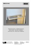
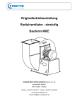
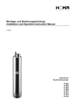
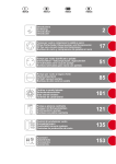
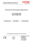
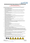
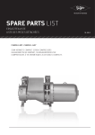
Installations- und
Betriebsanleitung
Installation and
Operating Instructions
Manuel d'installation
et de maintenance
Drehschieber-Pumpen Seco Print DC 0025 - 0080 B
Rotary Vane Pumps Seco Print DC 0025 - 0080 B
Pompes Rotatives à Palettes Seco Print DC 0025 - 0080 B
Installations- und Betriebsanleitung Seco Print DC 0025 - 0080 B
Installation and Operating Instructions Seco Print DC 0025 - 0080 B
Manuel d´installation et de maintenance Seco Print DC 0025 - 0080 B
1
Diese Betriebsanleitung hat Gültigkeit für folgen- These Installation and Operating Instructions are Ces instructions d´installation sont valables pour
de Pumpen:
valid for the following pumps:
les pompes suivantes:
- DC 0025 B
- DC 0040 B
- DC 0063 B
- DC 0080 B
- DC 0025 B
- DC 0040 B
- DC 0063 B
- DC 0080 B
Diese Betriebsanleitung ist vor der Installation und Inbetriebnahme der Vakuumpumpe unbedingt zu lesen und zu
befolgen.
- DC 0025 B
- DC 0040 B
- DC 0063 B
- DC 0080 B
It is mandatory that these operating instructions be read and understood prior to
Seco Print vacuum pump installation and
start-up.
Il est impératif que ce manuel d´instruction soit lu et compris avant de mettre
en marche une pompe à vide Seco Print.
Hersteller:
Manufacturer:
Constructeur:
Ateliers Busch S.A.
Zone Industrielle
CH 2906 Chevenez
Schweiz
Telefon: 032/ 4760200
Fax: 032/ 4760399
Ateliers Busch S.A.
Zone Industrielle
CH 2906 Chevenez
Switzerland
Phone: 032/ 4760200
Fax: 032/ 4760399
Ateliers Busch S.A.
Zone Industrielle
CH 2906 Chevenez
Suisse
Téléphone: 032/ 4760200
Fax: 032/ 4760399
Index
Inhaltsverzeichnis
Sicherheit
-Anwendung
-Sicherheitshinweise
Funktionsprinzip und Arbeitsweise
Transport und Verpackung
Inbetriebnahme
- Aufstellung
- Sauganschluß
Elektroanschluß
Betriebshinweise
Wartung
- Wartungstabelle
Informationen
Technische Daten
Verschleißteile
Zubehör
Ersatzteile
Explosionszeichnung
Seite
1
2
2
3
4
4-5
4
4-5
5
6
6-7
7
7
8
8
8
9-10
9
Safety
-Application
-Safety instructions
Principle of operation
Transport and packing
Start-up
- Setting-up
- Inlet connection
Electrical connection
Operating advice
Maintenance
- Table of maintenance
Information
Technical data
Wearing parts
Accessories
Spare parts
Exploded view drawing
Index
page
1
2
2
3
4
4-5
4
4-5
5
6
6-7
7
7
8
8
8
9-10
9
Sécurité
-Application
-Conseils de sécurité
Principe de fonctionnement
Transport et emballage
Démarrage
- Préparation
- Raccordement
Raccordement électrique
Conseils d´utilisation
Entretien
- Tableau de maintenance
Information
Spécifications techniques
Pièces d'usure
Accessoires
Pièces détachées
Vue éclatée
page
1
2
2
3
4
4-5
4
4-5
5
6
6-7
7
7
8
8
8
9-10
9
Sicherheit
Safety
Sécurité
Diese trockenlaufenden Vakuumpumpen sind nach
dem neuesten Stand der Technik und den anerkannten sicherheitstechnischen Regeln gebaut.
Dennoch können bei unsachgemäßer Installation
oder nicht bestimmungsgemäßem Betrieb Gefahren und Schäden entstehen.
These dry running vacuum pumps have been
manufactured according to the latest technical
standards and safety regulations. If not installed
properly or not used as directed, dangerous situations or damage might occur.
Ces pompes à vide sèches sont fabriquées selon
les plus récents standards techniques et règlements de sécurité connus. Une mauvaise installation ou une utilisation non conforme aux recommandations peut être dangereuse ou entraîner
des dommages.
Installations- und Betriebsanleitung Seco Print DC 0025 - 0080 B
Installation and Operating Instructions Seco Print DC 0025 - 0080 B
Manuel d´installation et de maintenance Seco Print DC 0025 - 0080 B
2
Anwendung
Diese Vakuumpumpen sind für den gleichzeitigen Einsatz als Vakuumpumpen und Verdichter
konzipiert. Sie können für das Absaugen oder
Fördern von Luft und trockenen Gasen verwendet
werden, die weder aggressiv, giftig noch explosiv
sind.
Andere Medien dürfen nicht gefördert werden.
Wenden Sie sich im Zweifelsfall an ihre örtliche
Busch-Vertretung.
Application
These vacuum pumps can be used simulta-neously
as vacuum pump and compressor. They can be
used to suck off or air or dry gases, which are not
aggressive, poisonous or explosive.
Flüssigkeiten und Feststoffe dürfen nicht in
die Pumpe gelangen.
Im Zweifelsfall unbedingt Rücksprache mit
Ihrer örtlichen Busch-Vertretung halten.
Liquid and solid particles must not enter
the pump.
In case of doubt consult your local Busch
Agency.
Des liquides et des particules solides ne
doivent pas entrer dans la pompe.
En cas de doute, veuillez consulter votre
Agence Busch locale.
Sicherheitshinweise
In dieser Betriebsanleitung werden jeweils vor
den betreffenden Handlungsschritten
Sicherheitshinweise genannt. Diese Hinweise
sind unbedingt zu beachten.
Safety advices
In this operating instruction safety measures are
adviced before each step. It is imperative that
these safety precautions are observed.
Conseils de sécurité
Dans cette notice de mise en service sont relevés
différentes manipulations de sécurité. Ces indications doivent être respectées à la lettre.
DC 0040 B
Fig. 2.1
3
1
2
3
4
5
6
7
1
Application
Ces pompes à vide peuvent être utilisées simultanément comme pompe à vide et compresseur.
Elles peuvent être utilisées pour aspirer ou refouler de l´air ou des gaz secs qui ne sont, ni agressifs, ni dangereux, ni explosifs.
Other agents must not be transported. In case of D´autres éléments ne doivent pas être aspirés par
doubt, please contact your local Busch Agency. ces pompes. En cas de doute, consulter votre
Agence Busch locale.
6
Sauganschluß
Druckanschluß
Vakuumbegrenzungsventil
Druckbegrenzungsventil
Drehrichtungspfeil
Abdeckung
Schraube zur Schieberkontrolle
4
5
1
2
3
4
5
6
7
2
Suction side
Pressure side
Vacuum relief valve
Pressure relief valve
Direction arrow label
Cover
Screw to access to the vanes
5
1
2
3
4
5
6
7
Aspiration
Refoulement
Soupape de réglage du vide
Soupape de réglage de la pression
Flèche sens rotation
Couvercle
Vis accédant aux palettes
Installations- und Betriebsanleitung Seco Print DC 0025 - 0080 B
Installation and Operating Instructions Seco Print DC 0025 - 0080 B
Manuel d´installation et de maintenance Seco Print DC 0025 - 0080 B
3
1
3
1
2
3
4
5
6
7
Fig. 3.1
2
4
Sauganschluß
Druckanschluß
Ansaugfilter (Zwischenansaugung)
Ansaugfilter
Rotor
Schieber
Filter
5
1
2
3
4
5
6
7
6
Gas inlet
Discharge
Inlet filter (inter-suction)
Inlet filter
Rotor
Vanes
Filter
7
1
2
3
4
5
6
7
Connection d´aspiration
Connection de refoulement
Filtre d'aspiration secondaire
Filtre d'aspiration principale
Rotor
Palettes
Filtre de refoulement
Funktionsprinzip und Arbeitsweise
Principle of operation
Principe de fonctionnement
Seco Print Vakuumpumpen arbeiten nach dem
Drehschieber-Prinzip ohne Einsatz von Fremdmedien zur Schmierung. Ein exzentrisch gelagerter Rotor (5) dreht sich im Zylinder. Durch die
Zentrifugalkraft der Drehbewegung werden die
Schieber (6), die in Schlitzen im Rotor gleiten an
die Zylinderwand gedrückt. Die Schieber teilen
den sichelförmigen Raum zwischen Zylinder
und Rotor in Kammern ein. Durch die unterschiedlichen Größen der Kammern entsteht auf
der Saugseite ein Unterdruck und auf der Druckseite ein Überdruck. Die Zwischenansaugung
ermöglicht, daß selbst bei geschlossener Saugseite Blasluft erzeugt wird. Die angesaugte Luft
wird im Ansaugfilter (4) gereinigt. Luft, die durch
die Zwischenansaugung in die Pumpe gelangt,
wird ebenfalls durch einen Ansaugfilter (3) gereinigt. Beide Filter gewährleisten, daß nur saubere
Luft in den Verdichtungsraum einströmt.
These pumps work according to the rotary vane
principle without the use of foreign mediums for
lubrication. An eccentrically installed rotor (5)
rotates in the cylinder. The centrifugal force of
rotation pushes the vanes (6), which are gliding
in slots in the rotor, towards the wall of the
cylinder. The vanes separate the sickle-shaped
space between rotor and cylinder wall in chambers. Because of the different size of the chambers there results a negative pressure at the
suction side and a positive pressure at the
pressure side. The intermediate suction renders
it possible air blast to be generated even with the
suction side closed. The ingetsed air is cleaned
in the inlet filter (4). Air that enters the pump by
the intermediate suction is also cleaned by an
inlet filter (3). Both filters guarantee only clean air
enters the compression chamber.
Ces pompes fonctionnent selon le principe des
pompes à palettes rotatives sans l´utilisation
d´un agent étranger pour la lubrification. Un rotor
(5) excentré tourne dans un cylindre. La force
centrifuge pousse les palettes (6), qui coulissent
librement dans leur logement, contre la paroi du
cylindre. Les palettes divisent l´espace libre en
forme de croissant en plusieurs chambres. Du
fait de la différence de volume des chambres, il
en résulte une dépression du côte aspiration et
une surpression du côte refoulement. Une aspiration secondaire permet d'obtenir une surpression même si le refoulement est fermé. L´air
aspiré passe au travers du filtre principal (4).
L´air, qui entre dans la pompe par l´aspiration
intermédiaire, est également purifié par un filtre
(3). Les deux filtres assurent la pénétration d'air
propre dans la chambre de compression.
Installations- und Betriebsanleitung Seco Print DC 0025 - 0080 B
Installation and Operating Instructions Seco Print DC 0025 - 0080 B
Manuel d´installation et de maintenance Seco Print DC 0025 - 0080 B
Transport und Verpackung
Transport and Packing
Die Seco Print Drehschieber-Pumpen werden im
Werk auf Funktion überprüft und fachgerecht
verpackt.
Der Sauganschluß und der Druckanschluß sind
mit einem Stopfen verschlossen, damit während
des Transportes kein Schmutz in die Pumpe gelangen kann. Dieser Stopfen mußen vor dem
Anlauf der Pumpe entfernt werden. Achten Sie bei
der Annahme der Pumpe auf Transportschäden.
Die Pumpe kann mittels einer Transportöse und
einer geeigneten Hebevorrichtung aus der Verpackung entnommen werden (siehe Fig. 4.1).
Seco Print rotary vane pumps pass a rigorous
operating test in the factory and are packed carefully to avoid transit damage.
The inlet and the outlet flange are sealed with a
plug, so no dirt can enter the pump during transport. Remove them before starting the vacuum
pump. Please check packing on delivery for transport damage.
The pump can be lifted from the packing with a
suitable lifting device using a lifting bracket (see
fig. 4.1).
4
Transport et emballage
Les pompes à vide rotatives à palettes Seco Print
sont testées et contrôlées dans notre usine avant
d´être soigneusement emballées.
Les brides d´aspiration et de refoulement sont
fermés par un protecteur qui évite la pénétration
de saletés pendant le transport. Avant de démarrer
la pompe, enlever les protecteurs. Veuillez vérifier
lors de la réception que l´emballage n´a pas subi
de dommages pendant le transport.
La pompe peut être sortie de son emballage en
utilisant les moyens de levage appropriés ainsi
que les anneaux de levage prévus à cet effet (fig.
Packing materials should be disposed of accor- 4.1).
ding to environmental laws or re-used.
Das Verpackungsmaterial ist nach den geltenden These operating instructions are part of the con- Les matériaux d´emballage doivent être éliminés
Bestimmungen zu entsorgen, bzw. wiederzu- signment.
selon les lois en vigueur ou doivent être réutilisés.
verwenden.
Diese Betriebsanleitung ist Bestandteil der LiefeCe manuel fait parti de notre envoi.
rung.
Fig. 4.1
Kranaufhängung
Lifting bracket
Anneau de levage
Inbetriebnahme
Start-up
Démarrage
Die Einhaltung der Reihenfolge der hier beschriebenen Arbeitsschritte ist für eine sicherheitsgerechte und funktionssichere Inbetriebnahme unbedingt erforderlich.
Die Inbetriebnahme darf nur von geschultem
Fachpersonal durchgeführt werden.
It is essential to observe the following instructions Il est impératif de suivre pas à pas les recommanstep by step to ensure a safe start-up.
dations suivantes pour assurer un démarrage
correct de la pompe.
1. Aufstellung
Die Pumpe muß waagrecht auf ebener Fläche
aufgestellt bzw. montiert werden.
Eine spezielle Befestigung ist nicht notwendig.
Durch die Innengewinde an den Schwingmetallpuffern kann die Pumpe angeschraubt werden.
1. Setting-up
The pump must be set up or mounted horizontally
on a flat surface.
Special mounting is not required, as the pump can
be mounted with screws through the threads of the
rubber feet of the pump.
Start-up may only be conducted by trained spe- Le démarrage doit être réalisé uniquement par un
cialists.
personnel qualifié.
1. Préparation
La pompe doit être placée ou fixée sur une surface plane horizontale.
Un montage spécial n´est pas nécessaire. Un trou
est prévu sous chaque support élastique pour une
fixation éventuelle.
Folgende Umgebungsbedingungen müssen ge- The following ambient operating environment must La pompe doit fonctionner dans l´environnement
geben sein:
be observed:
suivant:
Umgebungstemperatur: 12 - 30° C
Umgebungsdruck = Atmosphäre
Ambient temperature:
12 to 30° C
Ambient pressure = atmosphere
Température ambiante:
12 à 30° C
Pression ambiante = pression atmosphérique
Um ein Überhitzen der Pumpe zu vermeiden, ist In order to avoid over-heating of the pump, an Pour éviter un échauffement anormal de la pompe,
stets auf genügend Frischluftzufuhr zu achten.
undisturbed fresh air flow to the pump is neces- il faut prévoir une ventilation suffisante.
sary.
2. Sauganschluß
2. Inlet connection
2. Raccordement
Der Anschluß an den Saugflansch kann über The inlet flange can be connected with a vacuum- La bride d´aspiration peut être raccordée par une
einen vakuumdichten, flexiblen Schlauch oder tight flexible hose or pipe.
tuyauterie souple ou rigide étanche au vide.
durch Rohrleitungen erfolgen.
Dabei ist darauf zu achten, daß durch die Befesti- These pipes should cause no tension on the Cette tuyauterie ne doit exercer aucune contrainte
gung der Rohrleitung keine Spannungen auf die pump´s flanges. If necessary, compensators sur la bride d´aspiration; si nécessaire, installer
Pumpe übertragen werden. Gegebenenfalls müs- should to be installed.
des compensateurs.
sen Kompensatoren verwendet werden.
Verengungen in den Anschlußleitungen sind zu
vermeiden, da sonst die Saugleistung vermindert wird. Die Nennweite der Anschlußleitungen
muß mindestens dem Querschnitt des Saugflansches der Pumpe entsprechen.
Narrowing of the inlet and exhaust lines must be
avoided in order not to decrease the displacement
of the pump. The nominal diameter of the pipes
shoud be at least the same as the diameter of
pump´s inlet flange.
Il faut éviter les restrictions de tuyauteries qui
entrainent des diminutions de performances. Le
diamètre nominal doit être au moins égal au diamètre de la bride d´aspiration de la pompe à vide.
Installations- und Betriebsanleitung Seco Print DC 0025 - 0080 B
Installation and Operating Instructions Seco Print DC 0025 - 0080 B
Manuel d´installation et de maintenance Seco Print DC 0025 - 0080 B
Achten Sie darauf, daß sich keine Fremdkörper
(z.B. Schweißzunder) oder Flüssigkeiten in der
Ansaugleitung befinden. Diese können die Vakuumpumpe zerstören.
In der Abgasrohrleitung dürfen keine Absperrorgane eingebaut sein. Die Abgasleitung immer so
anbauen, daß kein Kondensat in die Pumpe gelangen kann (Gefälle, Syphon).
Achtung! Diese Vakuumpumpe läuft trokken.
Vakuumpumpe nicht mit Öl oder Fett
schmieren!
5
No foreign particles (e.g. solder soot) or liquids Aucune particule solide (par exemple: soudure)
may enter the inlet line, as they could destroy the ou liquide ne doit pénétrer dans la pompe, ce qui
vacuum pump.
pourrait la détruire.
Restricting devices should not be installed in the
exhaust line. Always connect the exhaust pipe in
a manner, so that no condensate can enter the
pump (slope, siphon).
Attention! This vacuum pump is a dry
running pump.
Do not lubricate the vacuum pump with oil
or grease.
Ne jamais installer d'organes d´arrêt dans la conduite d´échappement. Installer la conduite de façon à ce qu´aucun condensat ne puisse entrer
dans la pompe (pente, siphon).
Attention! Cette pompe à vide fonctionne à
sec.
Ne pas lubrifier la pompe à vide avec de
l´huile ou avec de la graisse.
Elektroanschluß
Electrical connection
Raccordement électrique
Die Elektroinstallation darf nur von
einem Fachmann durchgeführt
werden. Bestimmungen nach EMVRichtlinie 89/ 336/ EEC und Niederspannungsrichtlinie 73/ 23/ EEC,
sowie die entsprechenden ENNormen sind ebenso einzuhalten wie VDE/
EVU-Richtlinien bzw. örtliche oder nationale
Vorschriften. Der Betreiber der Vakuumpumpe hat dem Hersteller mitzuteilen, wenn
elektrische oder elektromagnetische Störungen aus seinem Netz zu erwarten sind.
Electrical installation may only
be conducted by a specialist.
Regulations following EMV Directive 89/ 336 EEC, low Voltage Directive 73/ 23 EEC, and the
appropriate EN Standards have
to be applied as well as VDE/ EVU regulations
and local or national regulations. The operator of the vacuum pump has to inform the
manufacturer, if electric or electromagnetic
interference from his mains is to be expected.
L'installation électrique ne doit être
effectuée que par un spécialiste. Les
directives 89/ 336/ CEE sur la compatibilité électromagnetique, 73/ 23/ CEE sur
la basse tension, ainsi que les directives VDE/ EVU et les réglementations
locales doivent être respectées. L'utilisateur
de la pompe à vide doit informer le constructeur, si le réseau est susceptible de provoquer
des interférences électriques ou électromagnétiques.
1. Die Spannungs- und Frequenzangaben auf 1.Voltage and frequency on the nameplate must 1. La tension et la fréquence indiquées sur la
dem Typenschild müssen mit der Netzspannung agree with the supply voltage.
plaque signalétique doivent correspondre aux
übereinstimmen.
caractéristiques du réseau.
2. Der Antriebsmotor ist nach VDE 0113 gegen
Überlastung abzusichern.
Bei ortsbeweglicher Aufstellung der Pumpe muß
der elektrische Anschluß mit Kabeldurchführungen ausgerüstet werden, welche die Funktion der
Zugentlastung übernehmen.
2. The drive motor must be protected against
overloads according to VDE 0113.
In the case of portable installation of the vacuum
pump, the electrical connection has to be equipped
with cable guides that have the function of traction
relief.
2. Le moteur électrique doit être protégé contre
des surcharges conformément à VDE 0113.
Lors d'une installation mobile de la pompe à vide,
le raccordement électrique doit être muni des
équipements nécessaires pour limiter la traction
sur le câble.
3. Zur Prüfung der Drehrichtung, Pumpe kurz ein- 3. To check the direction of rotation of the pump,
und ausschalten. Bei falscher Drehrichtung zwei flick the ON/OFF switch. In case of incorrect
Phasen umpolen.
direction reverse the polarity of any two of the
electrical phases.
3. Pour vérifier le sens de rotation de la pompe,
actionner le bouton ON/ OFF pendant un court
instant. Si le sens de rotation est mauvais, inverser deux des trois fils d´alimentation.
Von der Motorenseite aus gesehen ist die Dreh- Looking at the motor fan cover, the direction of Vu du côté moteur, le sens de rotation est le sens
richtung nach rechts, im Uhrzeigersinn.
rotation must be clockwise.
horaire.
Dreieckschaltung
Triangle connection
Connexion en triangle
Sternschaltung
Star connection
Connexion en étoile
L1
L1
W2
U2
V2
W2
V1
U1
L2
L3
L3
V1
U1
V2
W2
W1
V2
L1
U2
U2
W1
U1
W2
U1
V1
W1
W1
U2
V2
V1
Fig. 5.1
L2
L1
L2
L3
L3
L2
Installations- und Betriebsanleitung Seco Print DC 0025 - 0080 B
Installation and Operating Instructions Seco Print DC 0025 - 0080 B
Manuel d´installation et de maintenance Seco Print DC 0025 - 0080 B
6
Betriebshinweise
Operation advice
Conseils d´utilisation
1. Diese Vakuumpumpen sind für das Absaugen
bzw. Fördern von Luft und trockenen Gasen bestimmt, die weder aggressiv, giftig noch explosiv
sind.
Andere Medien dürfen nicht gefördert werden.
Wenden Sie sich im Zweifelsfall an Ihre örtliche
Busch-Vertretung.
1. These vacuum pumps can be used to evacuate 1. Ces pompes à vide peuvent être utilisées pour
air or dry gases, which are not aggressive, aspirer de l´air ou des gaz secs qui ne sont, ni
poisonous or explosive.
agressifs, ni dangereux, ni explosifs.
Other agents may not be transported. In case of Certains produits ne doivent pas être aspirés par
doubt, please contact your local Busch Agency. les pompes. En cas de doute, consulter votre
Agence Busch locale.
2. Seco Drehschieber-Pumpen arbeiten absolut 2. Seco rotary vane pumps work absolutly oil free. 2. Les pompes Seco Print fonctionnent sans aucune
ölfrei. Die Schieber sind aus Spezialkohle und The vanes are made of special carbon and not lubrification. Les palettes sont réalisées dans un
brauchen nicht geschmiert zu werden.
need any lubrication.
matériau à base de carbone spécial qui ne nécessite aucune lubrification.
Pumpe unter keinen Umständen mit Öl oder Caution: Do not lubricate with oil or grease Attention: N´utiliser aucun lubrifiant (huile ou
Fett schmieren!
under any circumstances.
graisse) sous aucun prétexte.
Vorsicht! Nicht geeignet für aggressive
und explosive Gase, Gasgemische und
Flüssigkeiten.
Attention! Not to be used with aggressive and explosive gases or gas mixtures
and fluids.
Attention! Ne pas utiliser avec des gaz
ou mélanges de gaz agressifs et/ ou
explosifs ni avec des liquides.
Achtung! Während des Betriebes kann
die Oberflächentemperatur der Pumpe
bis auf 80°C ansteigen. Verbrennungsgefahr!
Attention! During operation the surface
temperature of the pump can reach 80°C.
Attention! Pendant le fonctionnement la
température de surface de la pompe peut
atteindre 80°C.
Danger de brûlure!
Danger of burning!
2. Blasluft- und Vakuumregulierung
Seco Print Vakuumpumpen haben serienmäßig
Druck- und Vakuumventile (Fig. 2.1).
Die stufenlose Regulierung der Blasluft und des
Vakuums kann während des Betriebes vorgenommen werden. Dazu den Drehknopf am
jeweiligen Regulierventil drehen.
2. Pressure and vacuum adjustment
Seco Print vacuum pumps do have standard
pressure and vacuum valves (fig. 2.1).
Infinitely variable regulation of pressure and
vacuum can be made during operation. For that
turn the turning knob of the concerned regulating valve.
2. Réglage de la pression et du vide
Les pompes à vide Seco Print sont équipées en
série d´une vanne pour la pression et d´une vanne
pour le vide (fig 2.1).
Le réglage continu de la pression et du vide peut
être fait pendant le fonctionnement. Pour ce faire,
tourner la tête de la vanne de régulation concernée.
Hinweis! Werkseitig sind die Ventile auf die
Werte eingestellt, die auf dem Typenschild
angegeben sind. Eine seitliche Schraube
sichert die Ventile gegen versehentliches
Verstellen während des Transportes. Deshalb
muß vor dem Einstellen der Blasluft, bzw. des
Vakuums die Schraube gelöst werden.
Notice! The valves are calibrated by the
manufacturer to the values indicated on the
nameplate. A screw at the side prevents an
adjustment by mistake during transport. The
screw must be loosened before adjusting
the pressure or vacuum.
Remarque! Les vannes sont réglées d´usine
aux valeurs indiquées sur la plaquette. Une vis
latérale évite le déréglage de la vanne durant le
transport. C´est pourquoi, avant un réglage de
la pression ou du vide il faut dévisser cette vis.
The inlet pressure do not be less than
400 hPa (abs).
The overpressure do not be higher than
1600 hPa (abs).
La pression finale ne doit pas être inférieure à 400 hPa (abs).
La surpression ne doit pas être supérieure à 1600 hPa (abs).
Der Ansaugdruck sollt nicht kleiner als
400 hPa (abs) sein.
Der Überdruck sollt nicht größer als
1600 hPa (abs) sein.
Wartung
Maintenance
Entretien
Zu allen Wartungsarbeiten muß die Vakuum- The vacuum pump must be switched off and Avant tout travail d´entretien, il faut s´assurer
pumpe ausgeschaltet werden und gegen secured against accidental switch-on for all que la pompe a bien été arrêtée et que tout
versehentliches Anschalten gesichert sein. maintencance.
démarrage accidentel est impossible.
1. Die beiden saugseitigen Filter (Fig. 3.1) müssen in regelmäßigen Abständen gereinigt werden. Je nach Staubanfall müssen diese Filter
nach 100 bis 500 Betriebsstunden mit Druckluft
ausgeblasen werden. Bei starker Verschmutzung müssen die Filter ausgetauscht werden.
Dazu kann die Abdeckung abgenommen werden. (Fig. 9.1, 55).
1. The two filters on the suction side (fig. 3.1)
must be cleaned at regular intervals. Depending
on the amount of dust in the air being pumped the
filters must be blown out every 100 to 500
working hours with compressed air. If the
cartridge is too dirty to be cleaned, it must be
replaced by removing the cover. (fig. 9.1, 55).
1. Les deux filtres d'aspiration (fig. 3.1) doivent
être nettoyés à des intervalles réguliers qui sont
fonction de la quantité de poussières contenue
dans le gaz aspiré. Les filtres doivent être
soufflés avec de l´air comprimé après 100 à 500
heures de fonctionnement. Si les filtres sont trop
sales,les remplacer en enlevant le couvercle.
(fig. 9.1, 55).
Installations- und Betriebsanleitung Seco Print DC 0025 - 0080 B
Installation and Operating Instructions Seco Print DC 0025 - 0080 B
Manuel d´installation et de maintenance Seco Print DC 0025 - 0080 B
7
2. Nach jeweils 500 Betriebsstunden müssen die
Kühlkanäle mit Druckluft ausgeblasen werden.
Dazu die stirnseitige Abdeckung (Fig. 2.1,6)
abschrauben.
2. After every 500 working hours the cooling
pipes must be blown out with compressed air.
For this remove the cover (fig. 2.1, 6) on the front
side.
2. Après 500 heures de fonctionnement, purger
le canal de refroidissement avec de l´air comprimé. Pour cela, dévisser le couvercle (fig.
2.1,6) sur la face avant .
3. Die Kühlschlangen und die Lüfterhaube am
Motor sind regelmäßig auf Verschmutzung zu
überprüfen. Eine Verschmutzung der Lüfterhaube
oder der Kühlschlangen verhindert die Kühlluftzufuhr und kann zum Überhitzen der Pumpe führen.
3. The cooling spiral and the fan hood on the
motor must be checked regularly for dirt. Soiling
of the fan hood or of the cooling spiral prevents
cool air intake and may lead to overheating of the
vacuum pump.
3. Contrôler régulièrement la propreté des serpentins et du capot de ventilateur. Un encrassement empêche une bonne ventilation et peut
provoquer un échauffement anormal de la pompe
à vide.
4. Der druckseitige Filter muß nach 1000 bis 4. The pressure side filter must be replaced after 4. Remplacer le filtre de refoulement après 10002000 Betriebsstunden ausgewechselt werden. 1000 to 2000 working hours. For that the cover 2000 heures de fonctionnement. Pour cela,
enlever le couvercle. (fig. 9.1, 60)
Dazu kann die Abdeckung entfernt werden. (Fig. is removed. (fig. 9.1, 60)
9.1, 60)
5. Die Höhe der Schieber ist nach 2000 Betriebsstunden erstmalig zu überprüfen. Danach muß
die Schieberhöhe alle 1000 Betriebsstunden
überprüft werden.
Wenn die Höhe der Schieber das Mindestmaß
unterschreitet, müssen die Schieber ersetzt
werden. Zur Kontrolle (Fig. 7.1), entweder die
stirnseitige Abdeckung (Fig. 2.1,6) und den
Flansch abschrauen und die Abmessung ''A''
messen oder die Schraube (Fig. 2.1.7)
abschrauben und die Abmessung ''B'' messen.
Die ausgetauschten Filter und Schieber müssen
nach den geltenden Umweltvorschriften entsorgt
werden.
5. The height of the vanes must first be checked
after 2000 working hours. Afterwards the height
of the vanes must be checked every 1000
working hours.
If the height of the vanes is below the minimum,
they must be replaced. To check the vanes (fig.
7.1), remove the cover (fig. 2.1, 6), unscrew the
flange and measure the dimension ''A'' or unscrew
the screw (fig. 2.1.7) and measure the dimension
''B''.
6. Die Lager sind lebensdauergeschmiert.
6. Sealed for life bearings.
Informationen
The exchanged filters and vanes should be
disposed of according to environmental laws. Les filtres et les palettes remplacés doivent être
éliminés selon les lois en vigueur.
Wartungsarbeit
Service job
Type d´intervention
Reinigung
Cleaning
Nettoyage
Austausch
Replacement
Changement
Austausch
Replacement
Changement
Kontrolle
Checking
Contrôle
Kontrolle
Checking
Contrôle
Reinigung
Cleaning
Nettoyage
Kontrolle (nur durch Fachmann)
Checking (only to by a specialist)
Contrôle (par un spécialiste seulement)
6. Les roulements sont graissés à vie.
Zeitabstand
Interval
Périodicité
Mindesthöhe der Schieber
Min. height of the vanes
Palettes hauteur minimum
100 - 500 h
B
Wartungstabelle
Table of maintenance
Tableau de maintenance
Ansaugfilter
Inlet filter
Filtre d´aspiration principal
Ansaugfilter (Zwischenansaugung)
Inlet filter (Inter-suction)
Filtre d´aspiration secondaire
Filter Druckseite
Filter pressure side
Filtre de refoulement
Schieber
Vanes
Palettes
Kühlkanäle
Cooling ducts
Canaux d´aspiration
Lüfterhaube
Fan cover
Capot ventilateur
Elektroanschluß
Electrical connection
Raccordement électrique
5. La hauteur des palettes doit être contrôlée
après 2000 heures de fonctionnement pour la
première fois. Ensuite, la vérifier toutes les 1000
heures de fonctionnement.
Si la hauteur des palettes est inférieure à la
hauteur minimum, remplacer les palettes. Pour
vérifier les palettes (fig. 7.1), enlever le couvercle (fig. 2.1, 6) et la bride et mesurer la cote ''A''
ou enlever la vis (fig. 2.1.7) et mesurer la cote
''B''.
1000 - 2000h
1000 - 2000 h
1000 h
halbjährlich
half yearly
tous les 6 mois
halbjährlich
half yearly
tous les 6 mois
halbjährlich
half yearly
tous les 6 mois
Information
Weitere Informationen senden wir Ihnen auf We would be happy to supply further information
Anfrage gerne zu.
if needed.
Verfügbar ist:
Available:
- Typenblatt DC 0025 - 0080 B
- Type sheet DC 0025 - 0080 B
Fig. 7.1
DC 0025/0040 B
A = 29 mm, B = 74 mm
DC 0063/0080 B
A = 33 mm, B = 68 mm
Information
Sur demande nous vous ferons parvenir avec
plaisir les documents suivants.
Document disponible:
- Documentation commerciale DC0025- 0080 B
Installations- und Betriebsanleitung Seco Print DC 0025 - 0080 B
Installation and Operating Instructions Seco Print DC 0025 - 0080 B
Manuel d´installation et de maintenance Seco Print DC 0025 - 0080 B
Ersatzteile/ Zubehör
8
Spare parts and accessories
Pièces détachées et accessoires
Um einen sicheren Betrieb der Seco Print To guarantee safe operation of the Seco Print Pour garantir le meilleur fonctionnement des pomVakuumpumpe zu gewährleisten, dürfen nur vacuum pump, only original spare parts and pes à vide Seco Print, seulement des pièces
Original-Ersatzteile und -zubehör verwendet accessories should be used.
d'origine doivent être utilisées.
werden.
Bei Bestellung von Ersatzteilen und Zubehör stets When ordering spare parts and accessories, al- Lors de commande de pièces détachées et
Pumpentyp und die Maschinennummer angeben. ways state pump type and serial number.
d´accessoires, le type et le numéro de série de la
pompe doivent toujours être indiqué.
Die Teilenummern können Sie aus den Ersatzteilund Zubehörtabellen entnehmen.
Please find the part number in the spare parts list. La référence de chaque pièce se trouve sur la liste
des pièces détachées.
Wir verfügen über ein ausgedehntes Sortiment an
Zubhör für jeden Anwendungsbereich. Informa- An extensive assortment of accesssoires for every Nous disposons d´une vaste gamme d´accestionen über verschiedene Möglichkeitenstellen wir scope are available. We are happy to assist with soires pour chaque application. Nous sommes à
Ihnen gerne zur Verfügung.
any customer requests for special applications. votre disposition pour vous documenter sur nos
diverses possibilités.
Technische Daten
Technical Data
Spécifications Techniques
Nennsaugvermögen
Nominal displacement
Débit nominal
Ansaugdruck
Inlet Pressure
Pression d'aspiration
Verdichtungsenddruck
Discharge pressure
Pression de refoulement
Motornennleistung 3~
Nominal motor rating 3~
Puissance nominale du moteur 3~
Motornenndrehzahl
Nominal motor speed
Vitesse de rotation nominale
Schalldruckpegel(DIN 45635)
Sound level (DIN 45635)
Niveau sonore (DIN 45635)
Temperatur Blasluft
Temperature compressed air
Température de l´air comprimé
Gewicht
Weight
Poids
DC 0025 B
DC 0040 B
DC 0063 B
DC 0080 B
50 Hz m3/h
25
40
63
80
60 Hz m3/h
30
48
77
96
hPa (abs)
400
400
400
400
hPa (abs)
1600
1600
1600
1600
50 Hz kW
1,3
1,7
2,2
3,0
60 Hz kW
50 Hz min-1
1,7
1500
2,2
1500
3,0
1500
4,0
1500
60 Hz min-1
1800
1800
1800
1800
dB (A)
< 72
< 74
< 76
< 78
°C
42
45
48
52
kg
52
68
83
93
Verschleißteile
Wearing parts
Pièces d´usure
Dichtungssatz
Set of seals
Pochette de joints
Verschleißteilsatz
Overhaul kit
Kit complet
Beschreibung
Description
Description
bestehend aus allen notwendigen Dichtungen
consisting of all necessary seals
0990 000 461 0990 000 461 0990 000 462 0990 000 462
comporte tous les joints nécessaires
bestehend aus Dichtungssatz und sämtlichen Verschleißteilen
0994 000 001 0994 000 002 0994 000 003 0994 000 004
consisting of seal set and all wearing parts
comporte tous les joints et pièces d´usure
Zubehör
Accessories
Accessoires
Luftfilter
Inlet filter
Filtre d´aspiration
Beschreibung
Description
Description
Stehend, Anschluß G3/4
Vertical, inlet G3/4
Vertical, raccord G3/4
DC 0025 B
DC 0025 B
DC 0040 B
DC 0040 B
DC 0063 B
DC 0063 B
DC 0080 B
DC 0080 B
0945 501 916 0945 501 916 0945 504 333 0945 504 333
Falls Sie Fragen zu unserem Zubehörprogramm In case of question about our accessory program Nous sommes à votre disposition pour vous
haben wenden Sie sich an uns, wir beraten Sie feel free to contact us, we will be happy to assist. documenter sur notre programme d'accessoires.
gerne.
Installations- und Betriebsanleitung Seco Print DC 0025 - 0080 B
Installation and Operating Instructions Seco Print DC 0025 - 0080 B
Manuel d´installation et de maintenance Seco Print DC 0025 - 0080 B
Fig. 9.1
abgebildet
show
vue
9
DC 0025 - 0080 B
DC 0025 - 0080 B
DC 0025 - 0080 B
xx
nur DC 0025 - 0040 B
only DC 0025 - 0040 B
seulement DC 0025 - 0040 B
xx*
nur DC 0060 - 0080 B
only DC 0063 - 0080 B
seulement DC 0060- 0080 B
Teilenummern Ersatzteile
Part numbers spare parts
Numéro de pièce
Pos.
1
5
8
10
12
15
17
18
21
22
23
25
26
28
29
30
31
33
35
Teil
Zylinder
Rotor
Schieber
Zylinderdeckel A-Seite
Schlauch
Schrägkugellager
Halbrundkerbnagel
Gewindestift
Zylinderschraube
Federring
Paßring
Lagerdeckel
Zylinderschraube
Zylinderdeckel B-Seite
Gewindestift
Schlauch
WDR
Zylinderrollenlager
Zylinderstift
Part
Cylinder
Rotor
Vane
A - endplatte
Hose
Angular ball bearing
Round head grooved pin
Hexagon socket set screw
Cylinder cover screw
Lock washer
Washer
Bearing cover
Cylinder cover screw
B - endplatte
Hexagon socket set screw
Hose
WDR
Cylindrical roller bearing
Parallel pin
Pièce
Cylinder
Rotor
Palette
Flasque A
Tuyau
Roulement à billes
Clou à tête demi-ronde
Vis sans tête
Vis à tête cylindrique
Rondelle élastique
Rondelle
Couvercle de palier
Vis à tête cylindrique
Flasque B
Vis sans tête
Tuyau
WDR
Roulement à rouleaux
Goupille cylindrique
Qt
1
1
7
1
1
1
2
1
6
8
1
1
3
1
2
1
1
1
4
DC 0025 B
0223 000 911
0210 000 800
0722 000 014
0233 000 907
0570 000 189
0473 000 260
0413 000 327
0432 000 060
0433 000 051
0243 000 558
0413 000 205
0233 000 906
0414 000 204
0570 000 189
0487 000 076
0473 000 117
0437 000 368
DC 0040 B
0223 000 912
0210 000 801
0722 000 015
0233 000 907
0570 000 189
0473 000 260
0437 000 353
0413 000 327
0432 000 060
0433 000 051
0243 000 558
0413 000 205
0233 000 906
0414 000 204
0570 000 189
0487 000 076
0473 000 117
0437 000 368
DC 0063 B
0223 000 909
0210 000 802
0722 000 016
0233 000 913
0570 000 188
0473 000 262
0437 000 353
0414 000 204
0413 000 431
0432 000 062
0433 000 052
0243 000 565
0413 000 751
0233 000 912
0414 000 204
0570 000 188
0487 000 140
0473 000 118
0437 000 368
DC 0080 B
0223 000 910
0210 000 803
0722 000 017
0233 000 913
0570 000 188
0473 000 262
0437 000 353
0414 000 204
0413 000 431
0432 000 062
0433 000 052
0243 000 565
0413 000 751
0233 000 912
0414 000 204
0570 000 188
0487 000 140
0473 000 118
0437 000 368
Installations- und Betriebsanleitung Seco Print DC 0025 - 0080 B
Installation and Operating Instructions Seco Print DC 0025 - 0080 B
Manuel d´installation et de maintenance Seco Print DC 0025 - 0080 B
10
Teilenummern Ersatzteile
Part numbers spare parts
Numéro de pièce
Pos.
36
37
40
41
41
44
46
47
50
51
52
53
54
55
56
57
58
58
59
60
63
72
73
74
76
83
84
85
86
87
98
99
100
102
103
104
106
107
107
109
113
114
115
120
120
120.1
120.1
120.2
120.2
120.3
120.3
120.4
120.4
121
122
124
125
126
127
128
132
133
134
135
136
137
140
Teil
Zylinderschraube
Federring
Lagerdeckel
Zylinderschraube
Senkschraube
Abdeckhaube
Zylinderschraube
Federring
Zylinderschraube
Federring
Filterpatronne
Filterpatronne
Federbügel
Filterdeckel
Federbügel
Halbrundkerbnagel
Dichtung
Deckel
Dichtung
Filterdeckel
Filterpatronne
Stopfen
Zylinderschraube
Dichtring
Kühler
Distanzring
Zylinderschraube
Federring
Paßfeder
Ventilator
Zylinderschraube
Spannscheibe
Federring
Schutzring
Schutzring
Motorflansch
Zylinderschraube
Scheibe
Federring
Kupplungsnabe
Gewindestift
Kupplungsscheibe
Mitnehmerbolzen
Elektromotor (50 Hz)
Elektromotor (60 Hz)
Klemmbrett (50 Hz)
Klemmbrett (60 Hz)
Klemmkasten (50 Hz)
Klemmkasten (60 Hz)
Lüfterflügel (50 Hz)
Lüfterflügel (60 Hz)
Elektromotorhaube (50 Hz)
Elektromotorhaube (60 Hz)
Zylinderschraube
Federring
Gewindestift
Schwingmetallpuffer
Sechskantmutter
Federring
Gewindestift
Vakuumregulierventil
Druckregulierventil
Ölschauglasdichtung
Ölschauglasdichtung
Typenschild
Kegelstopfen
Ringschraube
Part
Cylinder cover screw
Lock washer
Bearing cover
Cylinder cover screw
Slotted head screw
Covering hood
Cylinder cover screw
Lock washer
Cylinder cover screw
Lock washer
Filter cartridge
Filter cartridge
Spring band
Cover
Spring band
Round head grooved pin
Seal
Cover
Seal
Cover
Filter cartridge
Plug
Cylinder cover screw
Sealing ring
Cooler
Range ring
Cylinder cover screw
Lock washer
Parallel key
Ventilator
Cylinder cover screw
Sleeve
Lock washer
Guard ring
Guard ring
Motor flange
Cylinder cover screw
Plate
Lock washer
Coupler hub
Hexagon socket set screw
Clutch disk
Driving pin
Motor (50 Hz)
Motor (60 Hz)
Terminal board (50 Hz)
Terminal board (60 Hz)
Terminal box (50 Hz)
Terminal box (60 Hz)
Fan (50 Hz)
Fan (60 Hz)
Motor fan cover (50 Hz)
Motor fan cover (60 Hz)
Cylinder cover screw
Lock washer
Hexagon socket set screw
Rubber feet
Hexagon nut
Lock washer
Hexagon socket set screw
Vacuum relief valve
Pressure relief valve
Oil sight glass seal
Oil sight glass seal
Nameplate
Conical plug
Lifting eye bolt
Pièce
Vis à tête cylindrique
Rondelle élastique
Couvercle de palier
Vis à tête cylindrique
Vis à tête fraisée fendue
Capot
Vis à tête cylindrique
Rondelle élastique
Vis à tête cylindrique
Rondelle ressort
Cartouche de filtre
Cartouche de filtre
Bride de ressort
Couvercle
Bride de ressort
Clou à tête demi-ronde
Joint
Couvercle
Joint
Couvercle
Cartouche de filtre
Bouchon
Vis à tête cylindrique
Anneau de joints
Radiateur
Rondelle d'écartement
Vis à tête cylindrique
Rondelle ressort
Clavette
Ventilateur
Vis à tête cylindrique
Douille
Rondelle élastique
Anneau de garde
Anneau de garde
Flasque de moteur
Vis à tête cylindrique
Plaque
Rondelle élastique
Moyeu d'accouplement
Vis sans tête
Disque d'embrayage
Broche d'entraînement
Moteur électrique (50 Hz)
Moteur électrique (60 Hz)
Bornier (50 Hz)
Bornier (60 Hz)
Boîte à bornes (50 Hz)
Boîte à bornes (60 Hz)
Ventilateur (50 Hz)
Ventilateur (60 Hz)
Capot de ventilateur (50 Hz)
Capot de ventilateur (60 Hz)
Vis à tête cylindrique
Rondelle ressort
Vis sans tête
Support plastique
Ecrou hexagonal
Rondelle ressort
Vis sans tête
Soupape de réglage vide
Soupape de réglage pression
Joint du voyant d'huile
Joint du voyant d'huile
Plaquette signalétique
Bouchon conique
Vis à anneau de levage
Qt
6
6
1
3
3
1
2
2
8
8
1
1
1
1
2
3
1
1
1
1
1
1
1
1
1
1
4
4
1
1
1
1
1
1
1
1
4
4
4
1
1
1
4
1
1
1
1
1
1
1
1
1
1
4
4
1
3
1
1
2
1
1
1
1
1
1
1
DC 0025 B
0413 000 327
0432 000 060
0243 000 559
0413 000 205
0728 000 011
0413 000 428
0432 000 062
0413 000 336
0432 000 060
0532 000 014
0532 000 015
0436 000 027
0247 000 771
0436 000 028
0437 000 352
0480 000 306
0480 000 306
0247 000 771
0532 000 030
0851 000 036
0413 000 304
0484 000 010
0918 000 204
0413 000 446
0432 000 062
0434 000 052
0947 000 660
0413 000 428
0460 000 947
0432 000 062
DC 0040 B
0413 000 327
0432 000 060
0243 000 559
0413 000 205
0728 000 011
0413 000 428
0432 000 062
0413 000 336
0432 000 060
0532 000 014
0532 000 015
0436 000 027
0247 000 771
0436 000 028
0437 000 352
0480 000 306
0480 000 306
0247 000 771
0532 000 030
0851 000 036
0413 000 304
0484 000 010
0918 000 204
0413 000 446
0432 000 062
0434 000 052
0947 000 660
0413 000 428
0460 000 947
0432 000 062
0246 000 809
0413 000 433
0431 000 045
0282 000 903
0414 000 201
0512 000 273
0614 502 819
0614 000 721
0648 000 401
0648 000 401
0648 509 994
0648 509 994
0648 509 995
0648 509 995
0648 509 996
0648 509 996
0413 000 428
0432 000 062
0414 000 228
0561 000 001
0420 000 035
0432 000 012
0414 000 221
0916 530 002
0916 530 012
0480 000 271
0480 000 271
0565 000 134
0851 000 036
0416 000 023
0246 000 809
0413 000 433
0431 000 045
0282 000 903
0414 000 204
0512 000 273
0615 503 893
0615 000 821
0648 000 401
0648 000 401
0648 509 994
0648 509 994
0648 509 995
0648 509 995
0648 509 996
0648 509 996
0413 000 428
0432 000 062
0414 000 228
0561 000 001
0420 000 035
0432 000 012
0414 000 221
0916 530 002
0916 530 012
0480 000 271
0480 000 271
0565 000 134
0851 000 036
0416 000 023
DC 0063 B
0413 000 431
0432 000 062
0243 000 564
0413 000 751
0728 000 012
0413 000 428
0432 000 062
0413 000 446
0432 000 062
0532 000 019
0532 000 017
0247 000 772
0436 000 028
0437 000 352
0247 000 772
0480 000 295
0532 000 025
0851 501 668
0413 000 304
0484 000 010
0918 000 205
0460 000 295
0413 000 446
0432 000 062
0434 000 054
0947 000 663
0413 000 431
0460 000 924
0432 000 062
0566 000 604
0566 000 605
0246 000 811
0413 000 431
0432 000 062
0282 000 905
0414 000 204
0512 000 140
0322 000 255
0620 502 822
0621 000 121
0648 000 401
0648 000 401
0648 509 984
0648 509 984
0648 000 303
0648 000 303
0648 000 018
0648 000 018
0413 000 428
0432 000 062
0414 000 221
0561 000 002
0916 530 002
0916 530 012
0480 000 271
0565 000 134
0480 000 271
0851 501 668
0416 000 023
DC 0080 B
0413 000 431
0432 000 062
0243 000 564
0413 000 751
0728 000 012
0413 000 428
0432 000 062
0413 000 446
0432 000 062
0532 000 019
0532 000 017
0247 000 772
0436 000 028
0437 000 352
0247 000 772
0480 000 295
0532 000 025
0851 501 668
0413 000 304
0484 000 010
0918 000 205
0460 000 295
0413 000 446
0432 000 062
0434 000 054
0947 000 663
0413 000 431
0460 000 924
0432 000 062
0566 000 604
0566 000 605
0246 000 811
0413 000 431
0432 000 062
0282 000 905
0414 000 204
0512 000 140
0322 000 255
0621 502 823
0622 000 215
0648 000 401
0648 509 997
0648 509 984
0648 509 998
0648 000 303
0648 000 304
0648 000 018
0648 000 019
0413 000 428
0432 000 062
0414 000 221
0561 000 002
0916 530 002
0916 530 012
0480 000 271
0565 000 134
0480 000 271
0851 501 668
0416 000 023
Installations- und Betriebsanleitung Seco Print DC 0025 - 0080 B
Installation and Operating Instructions Seco Print DC 0025 - 0080 B
Manuel d´installation et de maintenance Seco Print DC 0025 - 0080 B
Dr.- Ing. K. Busch GmbH
Postfach 1251
D 79689 Maulburg
Telefon (07622) 681-0
Telefax (07622) 5484
http://www.busch.de
Busch weltweit im Kreislauf der Industrie
Busch all over the world in industry
Busch Au cœur de l'industrie dans le monde entier
Amsterdam,Barcelona,Basel,Birmingham,Brussels,Copenhagen,Dublin,Gothenburg,Helsinki,Istanbul,KualaLumpur,Melbourne,Milan,Montreal,Moscow,NewYork,NewPlymouth,Oslo,Paris,SanJose,Seoul,Singapore,Taipei,Tokyo,Vienna
Technische Änderungen vorbehalten/ Technical changes reserved/ Sujet à modifications techniques.
Printed in Switzerland / BA - 12/C (C) - 0335 D, E, F