1
FR
FRANCAIS
EN
ENGLISH
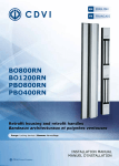
BO600RH
Horizontal retrofit housing
Bandeau architectural horizontal
Range: Locking devices / Gamme: Verrouillage
INSTALLATION MANUAL
MANUEL D’INSTALLATION
Group Company
INSTALLATION MANUAL
EN
BO600RH
Horizontal retrofit housing
Thank you for buying our products and for the confidence you placed
in our company.
Holding force: 2 x 300kg,
Dimensions (L x W x D): 925 x 105 x
62mm.
Magnet housing for frame mount.
Armature housing with end caps
for door mount.
Input voltage: 12/24/48V dc.
Consumption:
- 12V dc = 550mA (per magnet),
- 24V dc = 275mA (per magnet),
- 48V dc = 190mA (for both magnets).
2
cdvi.com
cdvigroup.com
DOOR LEAF
Pre-assembled.
Fast installation.
Covers previous installation
fixing holes.
Pre-drilled sections (adjustable).
Ergonomic design.
Aesthetic.
Suitable for metal, wood
and glass doors.
Ideal for retrofit applications.
Magnets supplied with terminal
blocks.
Groove at the back of the magnet
housing for cable management.
Magnet housing supplied
with cover.
Options:
- Aluminium rail spacers.
- Aluminium cable tray.
- Installation on glass door (UBK25).
- RAL colour.
- Cut to size.
FRAME
1] PRODUCTS OVERVIEW
MOUNTING
WEEE
TANCE
HIGH RESIS
ISM
TO VANDAL
CE Certification
-20°C to +70°C
Recommended
Power supplies
ARD212
BS602
INSTALLATION MANUAL
EN
BO600RH
Horizontal retrofit housing
Product Details
BO600RP
925 MM
BO600RPOPTION
925 MM
Number of 300Kg magnets
2
2
Lock section with cover
1
1
Architectural handle with fixing cover
1
1
End caps for handle
2
2
End caps for lock section
2
2
RAL colour (option)
-
Cut to size
-
2] INFORMATION & RECOMMENDATIONS
Power Considerations
The handle is designed to house electromagnets
with a holding force of 300Kg each. These units
can be supplied by either 12Vdc or 24Vdc
depending upon your preferred choice (48Vdc
supplied on special request). The current required
depends on the amount of electromagnetic locks,
and the voltage chosen – please see Technical
Specification, and ensure you have allocated
sufficient power to BO600RH (2500mm housing
with 2 magnetic locks) would require: PSU12/2
or ARD2/12 at 12Vdc PSU24/1 or ARD24 at 24Vdc.
Information
The electromagnets are pre-fitted within the lock
section. The armature plates are pre-fitted within
the architectural handle. Both sections are supplied
with end caps.
Wiring
Plan your cable routes before commencing
installation. We recommend a maximum distance
of 10m from the power supply to the electromagnetic
locks
(to prevent volt drop). If the distance
is greater, then make sure you have increased
the cross section of the cable to compensate.
General Advice
The 2 parts of the architectural housing are designed
to be surface mounted on the door and frame, where
they should be parallel when the door is closed.
If there is a rebate, then it will be necessary to pack out
the lower part to be parallel to the other (Aluminium
rail spacer, Ref: REO). You can also use the PRP800
(Reinforcement section) or ALMA (Aluminium Cable
tray) to reinforce the housing mounting.
3] PACKAGE CONTENTS
Profiled handle
with end caps
Profiled handle
fixing cover
Box section backBox section cover
plate
BO600RH
925 mm
1
1
1
1
2
BO600RHOPTION
925 mm
1
1
1
1
2
End caps
cdvi.com
cdvigroup.com
3
INSTALLATION MANUAL
BO600RH
Horizontal retrofit housing
EN
4] ASSEMBLY
Position the box-section backplate, complete with prefitted electro-magnetic locks, on to the door frame ensure the positioning will allow for the architectural
handle to close securely over the section. Once you
are satisfied with the position, mark the vertical
and horizontal holes, then drill as required. Take
note of the cable entry holes, and feed the cables
through. Fix the section into place, then wire the
electromagnetic locks in accordance with the wiring
schematic in Section 5. Fit the box section cover
into place, fix the end caps and secure with the M4
screws provided. To finalise the assembly, tighten
all fixings, and protect the handle fixing section by
fitting the cover and end caps.
4
cdvi.com
cdvigroup.com
With the door closed, position the architectural
handle onto the edge of the opening leaf of the door,
ensuring the handle covers the box-section. Mark
the vertical and horizontal holes, drill as required,
then temporarily fix the handle leaving a small gap
around the box section – check the alignment of the
magnets in the box section with the armatures in
the handle. Adjust if necessary, then once satisfied,
secure the handle by completing the fixings.
Insert the end caps and secure.
INSTALLATION MANUAL
EN
BO600RH
Horizontal retrofit housing
5] WIRING SCHEMATIC
Example N°1: Exit button only (VHLD timer optional)
BO600RH RANGE
12Vdc
24Vdc
Exit
Button
Electromagnetic lock
Voltage 12Vdc
or 24Vdc
300KG
Electromagnetic lock
300KG
OPTIONS
Time relay for magnetic locks (Ref: TPV)
Important: When using a timer in circuit, please
make note of the voltage used and ensure the
timer can operate at the same voltage
(example shows TPV)
Adjustable timer
(0 to 20 seconds)
5-Way Terminal Strip
– non monitored version
+ 12Vdc or 24Vdc positive *
- 12Vdc or 24Vdc negative *
* Voltage: 12Vdc or 24Vdc.
Place the « jumpers » to select
12Vdc or 24Vdc supply to your
magnetic locks
12Vdc
5-Way Terminal Strip –
monitored version
+
12Vdc or 24Vdc positive *
12Vdc or 24Vdc negative *
NC Contact «Normally Closed»
COM Common
NO Contact «Normally Open»
24Vdc
* Voltage: 12Vdc or 24Vdc.
Place the « jumpers » to select 12Vdc
or 24Vdc supply to your magnetic locks.
Example N°2: Access Control + Exit Button
Exit
Button
Access
Control
Unit
Voltage 12Vdc
or 24Vdc
BO600RH RANGE
12Vdc
24 Vdc
Electromagnetic lock
300KG
Electromagnetic lock
300KG
5-Way Terminal Strip
– non monitored version
+ 12Vdc or 24Vdc positive *
- 12Vdc or 24Vdc negative *
* Voltage: 12Vdc or 24Vdc.
Place the « jumpers » to select
12Vdc or 24Vdc supply to your
magnetic locks.
cdvi.com
cdvigroup.com
5
INSTALLATION MANUAL
BO600RH
Horizontal retrofit housing
EN
6] LIMITED LIFETIME WARRANTY [EXTRACT]*
CDVI warrants this product to be free from defects in material and workmanship, when it has been installed
in accordance with the manufacturer’s instructions and has not been modified or tampered with. Only product
recognized by CDVI to be defective should be returned under these warranty terms if accompanied
by an RMA (Return Material Authorization Number) provided by CDVI. CDVI, at its option, shall repair
or replace the defective product at CDVI premises or at any CDVI approved service center. This warranty
does not cover any damage due to accident, misuse, abuse or negligence. This warranty is valid only
if the product is registered, within 1 month from delivery to the final costumer. To obtain full details of this
warranty and to register the product to commence the “Limited Lifetime Warranty”, complete the enclosed
registration card and return it, either by e-mail or post, to the relevant CDVI address or completion of the
on line registration at www.cdvigroup.com. Repair or replacement of the defective product is the exclusive
remedy. CDVI shall not be liable for any incidental or consequential damages arising from any defect in, or
malfunction of, its product. In no event the entire liability can not exceed the purchase price of the product.
The CDVI local country contact details can be found on line by visiting www.cdvigroup.com or on the back
cover of the installation manual.
DISCLAIMER OF WARRANTY: EXCEPT AS STATED ABOVE, CDVI MAKES NO WARRANTIES, EITHER
EXPRESS OR IMPLIED, AS TO ANY MATTER WHATSOEVER, INCLUDING THE CONDITION OF ITS PRODUCTS,
THE TRANSPORTATION, THEIR MERCHANTABILITY OR FITNESS FOR ANY PARTICULAR PURPOSE.
7] NOTES
*Refer to Limited Lifetime Warranty conditions
6
cdvi.com
cdvigroup.com
MANUEL D’INSTALLATION
FR
BO600RH
Bandeau architectural horizontal
Merci pour l’achat de ce produit et pour la confiance que vous accordez
à notre entreprise.
Force du bandeau : 2 x 300 kg,
Dimensions (L x l x P) : 925 x 105 x 62 mm.
Poteau technique sur le dormant prévu
pour l’installation des ventouses.
Poignée bandeau sur l’ouvrant pour
l’installation des contre-plaques.
Bouchons ABS pour extrémités bandeaux
et poteau technique.
Alimentation : 12/24/48 V DC.
Consommation :
- 12 V DC = 550 mA (par ventouses),
- 24 V DC = 275 mA (par ventouses),
- 48 V DC = 275 mA (pour les 2 ventouses).
OUVRANT
Esthétique.
Installation sur tout type de porte
(huisserie métallique, bois et verre).
Idéal pour les rénovations.
Profils pré-percés (réglables).
Ventouses avec bornier
de raccordement pré-installées
sur le poteau technique.
Largeur recouvrant
les anciennes installations.
Passage des câbles facilité grâce
au bossage central à l’arrière
du poteau technique
(support des ventouses).
Capot de recouvrement du poteau
technique après montage.
Options :
- Rehausses en aluminium.
- Moulures en aluminium.
- Pose sur porte en verre (Réf : UBK25).
- Teinte RAL.
- Coupe.
DORMANT
1] PRÉSENTATION DU PRODUIT
TEMPS DE POSE
DEEE
TANCE
HAUTE RÉSIS
ISME
AU VANDAL
Certification CE
-20°C à +70°C
Alimentations
préconisées
ARD212
BS602
cdvi.com
cdvigroup.com
7
MANUEL D’INSTALLATION
FR
BO600RH
Bandeau architectural horizontal
Détail produits
BO600RH
925 MM
BO600RHOPTION
925 MM
Ventouse(s) 300 Kg
2
2
Support mural avec Capot
1
1
Poignée bandeau avec Cache vis
1
1
Bouchons Poignée bandeau
2
2
Bouchons Support mural
2
2
Possibilité de teinte
RAL (supplément)
-
Coupe
-
2] RAPPELS ET RECOMMANDATIONS
Alimentations préconisées
Le bandeau est conçu pour des ventouses ayant une
force de retenue chacune de 400 Kg, alimentées
sous 12 V DC ou 24 V DC. Prévoir une alimentation
suivant le branchement choisi. L’arrivée de courant
se fait coté fixe ou semi-fixe à l’aide d’un flexible
si nécessaire. Il existe deux alimentations adaptées
pour le BO600RH (avec 2 ventouses) :
- BS602 ou ARD2/12 en 12 V DC
- ADC24, AS6 ou BS24 en 24 V DC.
Câblage
Prévoir du fil 9/10 souple. Nous préconisons une
distance maximun de 10 mètres, entre la ventouse
et son alimentation. Si cette distance est supérieure,
prévoir le câble nécessaire à l’installation.
Conseils d’utilisation
Le bandeau s’installe sur des portes en tirant
et affleurantes à un ou deux vantaux (service/
semi-fixe). Il se pose sur des portes parfaitement
alignées, dans le cas contraire, il faut prévoir une
cale (Réf : REO). Vous pouvez également renforcer
votre porte avec le profil renfort (Ref: PRP800) et
cacher votre installation électrique avec le passecâble (Ref: ALMA).
Rappel
Les ventouses sont déjà montées sur le support
mural. La poignée bandeau est équipée en série des
contreplaques et des bouchons à chaque extrémité.
3] PACKAGE CONTENTS
Profil poignée
avec bouchons
Profil
cache-vis
Capot pour
support mural
Profil support
mural
Bouchons
casquette
BO600RH
925 mm
1
1
1
1
2
BO600RHOPTION
925 mm
1
1
1
1
2
8
cdvi.com
cdvigroup.com
MANUEL D’INSTALLATION
FR
BO600RH
Bandeau architectural horizontal
4] MONTAGE
Positionnez le support mural avec ses ventouses sur
le fixe ou semi fixe. Prenez les marques dans les
trous oblongs horizontaux et verticaux et percez la
surface du vantail au niveau des marques. Prévoyez
les sorties des câbles grâce au bossage central
à l’arrière du support mural et en vous aidant du
schéma de câblage des ventouses (page suivante).
Vissez le support mural et fixez les bouchons à chaque
extrémité du profil à l’aide des vis auto-taraudeuses
à tête bombée M4 (fournies). Positionnez le capot sur
le support mural et emboitez-le dans son logement.
Pour le bandeau, même procédure, installez le
cache vis dans sa charnière et emboitez-le dans son
logement.
Positionnez la poignée bandeau munie
de ses
contreplaques sur l’ouvrant. Prenez les marques
dans les trous oblongs horizontaux et verticaux
pour fixer la poignée bandeau. Percer la surface de
la porte au niveau des marques réalisées. Placez
et vissez provisoirement la poignée afin de laisser
un léger espace qui vous permettra d’effectuer le
réglage final de l’ensemble. Fermez la porte, vérifiez
que les ventouses sont bien positionnées face à leur
contreplaques puis fixez définitivement la poignée
bandeau. Présenter les cache-vis et les clipser dans
le profilé pour finaliser l’installation.
cdvi.com
cdvigroup.com
9
MANUEL D’INSTALLATION
FR
BO600RH
Bandeau architectural horizontal
5] SCHÉMAS DE RACCORDEMENT
Montage N°1 : Bouton poussoir intérieur (+ Carte TPV en option)
Bouton poussoir
(NO/NF)
intérieur
Alimentation
12 V ou 24 V DC
BO600RP
12Vdc
24Vdc
VENTOUSE N°1
+ Alimentation 12 V ou 24 V DC *
- Alimentation 12 V ou 24V DC *
OPTIONS
VENTOUSE N°2
Commande temporisée par TPV
Important :Lorsque la ventouse est équipée
d’un bornier, il est impératif d’enlever
les deux cavaliers du TPV.
* Alimentation : 12 V DC
ou 24 V DC. En fonction
du placement des cavaliers
vous alimentez votre ventouse
en 12 V DC ou en 24 V DC.
12 V DC 24 V DC
Bornier 5 points (ventouse)
+
Alimentation 12 V ou 24 V DC *
Alimentation 12 V ou 24V DC *
NC Contact «Normalement Fermé»
COM Commun
NO Contact «Normalement Ouvert»
* Alimentation : 12 V DC ou 24 V DC.
En fonction du placement des cavaliers
vous alimentez votre ventouse en 12 V DC
ou en 24 V DC.
Réglage de la temporisation
(de 0 à 20 secondes)
Montage N°2 : Contrôle d’accès + Bouton poussoir intérieur
Contrôle
d’accès
extérieur
(NF)
Temporisé
Alimentation
12 V ou 24 V DC
Bouton poussoir
(NF) intérieur
BO600RP
12Vdc
24 V DC
VENTOUSE N°1
Bornier 5 points (ventouse)
+ Alimentation 12 V ou 24 V DC *
- Alimentation 12 V ou 24V DC *
VENTOUSE N°2
10
cdvi.com
cdvigroup.com
* Alimentation : 12 V DC
ou 24 V DC. En fonction
du placement des cavaliers
vous alimentez votre ventouse
en 12 V DC ou en 24 V DC.
MANUEL D’INSTALLATION
FR
BO600RH
Bandeau architectural horizontal
6] CONDITIONS DE GARANTIE À VIE LIMITÉE [EXTRAIT]*
Les sociétés CDVI garantissent que ce produit est dépourvu de tout vice caché, tant dans les matériaux
que dans sa fabrication, à la condition, qu’il soit installé conformément aux préconisations du fabricant
et qu’il n’y ait pas eu d’interventions ou de modifications sur le produit. La responsabilité de CDVI se limite
à la réparation ou à l’échange du produit. CDVI n’assume aucune responsabilité concernant les dommages
sur les biens ou les personnes. Un produit reconnu défectueux par CDVI doit être retourné au serviceaprès-vente de CDVI, après l’obtention du numéro d’autorisation de Retour de Produit(s) Défectueux (RMA).
La responsabilité de CDVI se limite à la réparation ou au remplacement d’un produit ou pièces défectueuses,
en ses ateliers. L’une ou l’autre de ces interventions sont définis par le service-après-vente de CDVI.
Le préjudice imputable à CDVI ne saurait en aucun cas dépasser la valeur du produit. La responsabilité
de CDVI ne peut être engagée auprès de l’acheteur, installateur, client final ou qui que ce soit, lors de dommages
consécutifs à des imperfections ou mauvais fonctionnement du produit. Cette garantie prend effet
à la date d’enregistrement du produit auprès de CDVI, à partir de l’instant ou la date d’enregistrement est
dûment complétée, dans la limite d’un mois, après la date de livraison au client final. Pour obtenir les détails complets de cette garantie et enregistrer votre/vos produit(s) pour bénéficier de cette « Garantie à Vie
limitée ». Veuillez compléter la carte d’enregistrement présente dans la boite du produit et nous la retourner,
par email ou par courrier, à l’adresse de l’entité CDVI la plus proche ou vous enregistrer en ligne à l’adresse
www.cdvigroup.com. Les contacts des entités CDVI sont accessibles en ligne à l’adresse www.cdvigroup.com
ou au dos de la notice d’installation.
EXCLUSIONS DE LA GARANTIE : A l’EXCEPTION DES POINTS EVOQUES PRECEDEMMENT, CDVI N’APPLIQUE
AUCUNE GARANTIE, NI DELIBEREE NI TACITE, A TOUS LES PROBLEMES INCLUANT LE CONDITIONNEMENT,
LE TRANSPORT, LEUR COMMERCIALISATION OU LES CONDITIONS D’UTILISATIONS PARTICULIÈRES.
7] NOTES
*Voir conditions de garantie à vie limitée
cdvi.com
cdvigroup.com
11
Reference : G0301FR0386V01
Extranet : EXE-CDVI_IM BO600RH CMYK A5 EN-FR 01
CDVI Group
FRANCE (Headquarter/Siège social)
Phone: +33 (0)1 48 91 01 02
Fax: +33 (0)1 48 91 21 21
CDVI IBÉRICA
CDVI SWEDEN
[SPAIN - PORTUGAL]
[SWEDEN - DANEMARK - NORWAY - FINLAND]
Phone: +34 (0)935 390 966
Fax: +34 (0)935 390 970
Phone: +46 (0)31 760 19 30
Fax: +46 (0)31 748 09 30
CDVI
SUISSE
Phone: +41 (0)21 882 18 41
Fax: +41 (0)21 882 18 42
CDVI
ITALIA
Phone: +39 0331 97 38 08
Fax: +39 0331 97 39 70
CDVI UK
CDVI
CHINA
Phone: +86 (0)10 62414516
Fax: +86 (0)10 62414519
CDVI
MAROC
Phone: +212 (0)5 22 48 09 40
Fax: +212 (0)5 22 48 34 69
DIGIT
FRANCE
Phone: +33 (0)1 41 71 06 85
Fax: +33 (0)1 41 71 06 86
CDVI
FRANCE + EXPORT
Phone: +33 (0)1 48 91 01 02
Fax: +33 (0)1 48 91 21 21
CDVI
TAIWAN
Phone: +886 (0)42471 2188
Fax: +886 (0)42471 2131
CDVI AMERICAS
[CANADA - USA]
Phone: +1 (450) 682 7945
Fax: +1 (450) 682 9590
CDVI BENELUX
[BELGIUM - NETHERLAND - LUXEMBOURG]
Phone: +32 (0) 56 73 93 00
Fax: +32 (0) 56 73 93 05
Toutes les informations mentionnées à titre indicatif sur le présent document (photos, dessins, caractéristiques
techniques et dimensions) peuvent varier et sont susceptibles de modifications sans notification préalable.
All the information contained within this document (photos, drawing, features, specifications and dimensions)
could be perceptibly different and can be changed without prior notice.
Manufacturing Access Control since 1985
cdvigroup.com
[UNITED KINGDOM - IRELAND]
Phone: +44 (0)1628 531300
Fax: +44 (0)1628 531003