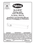
1
hatcocorp.com
Register Online!
(see page 2)
S'inscrire en ligne!
(voir page 12)
Narrow Display Lights
Tubes d'Éclairage Étroit
NLX Series/Série
Installation and Operating Manual
Manuel d'installation
et d'utilisation
07.04.560.00
P/N
WARNING
Do not operate this equipment unless you
have read and understood the contents of
this manual! Failure to follow the
instructions contained in this manual may
result in serious injury or death. This
manual contains important safety
information concerning the maintenance,
use, and operation of this product. If
you’re unable to understand the contents
of this manual, please bring it to the
attention of your supervisor. Keep this
manual in a safe location for future
reference.
English = p 2
ADVERTENCIA
No opere este equipo al menos que haya
leído y comprendido el contenido de este
manual! Cualquier falla en el seguimiento
de las instrucciones contenidas en este
manual puede resultar en un serio lesión
o muerte. Este manual contiene
importante información sobre seguridad
concerniente al mantenimiento, uso y
operación de este producto. Si usted no
puede entender el contenido de este
manual por favor pregunte a su
supervisor. Almacenar este manual en
una localización segura para la referencia
futura.
AVERTISSEMENT
Ne pas utiliser cet équipement sans avoir
lu et compris le contenu de ce manuel !
Le
non-respect
des
instructions
contenues dans ce manuel peut entraîner
de graves blessures ou la mort. Ce
manuel contient des informations
importantes
concernant
l'entretien,
l'utilisation et le fonctionnement de ce
produit. Si vous ne comprenez pas le
contenu de ce manuel, veuillez le signaler
à votre supérieur. Conservez ce manuel
dans un endroit sûr pour pouvoir vous y
référer plus tard.
Français = p 12
© 2013 Hatco Corporation
CONTENTS
English
Important Owner Information ..............................................2
Introduction ...........................................................................2
Important Safety Information...............................................3
Model Description.................................................................4
Model Designation ................................................................4
Specifications........................................................................5
Dimensions — Strip Heater ................................................5
Dimensions — Control Box ................................................5
Electrical Rating Chart .......................................................5
Installation .............................................................................6
General...............................................................................6
Installation Site Requirements............................................6
Installing the Unit ................................................................7
Installing the Control Box....................................................7
Operation ...............................................................................8
General...............................................................................8
Maintenance ..........................................................................9
General...............................................................................9
Daily Cleaning ....................................................................8
Replacing a Display Light Bulb...........................................9
Troubleshooting Guide ......................................................10
Options and Accessories...................................................10
Limited Warranty.................................................................11
Authorized Parts Distributors ............................Back Cover
IMPORTANT OWNER INFORMATION
Record the model number, serial number, voltage, and
purchase date of the unit in the spaces below (specification
label located on the side of the unit). Please have this
information available when calling Hatco for service assistance.
Business
Hours:
Serial No. ________________________________________
Telephone: 800-558-0607; 414-671-6350
Date of Purchase __________________________________
Fax:
Model No. ________________________________________
e-mail:
Voltage __________________________________________
Register your unit!
8:00
AM
to 5:00
PM
Central Standard Time (CST)
(Summer Hours: June to September—
8:00 AM to 5:00 PM CST Monday–Thursday
8:00 AM to 2:30 PM CST Friday)
[email protected]
800-690-2966 (Parts and Service)
414-671-3976 (International)
24 Hour 7 Day Parts and Service
Assistance available in the United States
and Canada by calling 800-558-0607.
Completing online warranty registration will prevent delay in
obtaining warranty coverage. Access the Hatco website at
www.hatcocorp.com, select the Parts & Service pull-down
menu, and click on “Warranty Registration”.
Additional information can be found by visiting our web site at
www.hatcocorp.com.
INTRODUCTION
Hatco NLX Series Narrow Display Lights provide effective and
stylish lighting for non-critical food holding and display areas.
The narrow housing of the NLX Series is ideal for installation in
tight spaces.
Safety information that appears in this manual is identified by
the following signal word panels:
This manual provides the installation, safety, and operating
instructions for NLX Series Narrow Display Lights. Hatco
recommends all installation, operating, and safety instructions
appearing in this manual be read prior to installation or
operation of a unit.
CAUTION indicates a hazardous situation which, if not
avoided, could result in minor or moderate injury.
WARNING
NLX Series Narrow Display Lights are products of extensive
research and field testing. The materials used were selected
for maximum durability, attractive appearance, and optimum
performance. Every unit is inspected and tested thoroughly
prior to shipment.
WARNING indicates a hazardous situation which, if not
avoided, could result in death or serious injury.
CAUTION
NOTICE
NOTICE is used to address practices not related to personal
injury.
2
Form No. NLXM-0913
IMPORTANT SAFETY INFORMATION
English
Read the following important safety information before using this equipment to avoid
serious injury or death and to avoid damage to equipment or property.
WARNING
WARNING
ELECTRIC SHOCK HAZARD:
• Unit must be installed by a qualified electrician.
Installation must conform to all local electrical codes.
Installation by unqualified personnel will void unit
warranty and may lead to electric shock or burn, as well
as damage to unit and/or its surroundings.
• Consult a licensed electrical contractor for proper
electrical installation conforming to local electrical
codes and the National Electrical Code (N.E.C.).
• When mounting above a steam table, each individual
well opening must not exceed 12" (30.5 mm) wide with
a maximum electrical rating of 2000 W per well.
• Turn OFF power at fused disconnect switch/circuit
breaker and allow unit to cool before performing any
cleaning, adjustments, or maintenance.
• DO NOT submerge or saturate with water. Unit is not
waterproof. Do not operate if unit has been submerged
or saturated with water.
• Do not clean unit when it is energized or hot.
• Unit is not weatherproof. Locate unit indoors where
ambient air temperature is a minimum of 70°F (21°C).
• Do not steam clean or use excessive water on the unit.
• This unit is not “jet-proof” construction. Do not use jetclean spray to clean this unit.
• Control box must be mounted in a vertical surface.
Mounting control box in a horizontal surface may result
in the collection of liquids and lead to electric shock.
• This unit must be serviced by qualified personnel only.
Service by unqualified personnel may lead to electric
shock or burn.
• Use only Genuine Hatco Replacement Parts when
service is required. Failure to use Genuine Hatco
Replacement Parts will void all warranties and may
subject operators of the equipment to hazardous
electrical voltage, resulting in electrical shock or burn.
Genuine Hatco Replacement Parts are specified to
operate safely in the environments in which they are
used. Some aftermarket or generic replacement parts
do not have the characteristics that will allow them to
operate safely in Hatco equipment.
FIRE HAZARD:
• Locate unit the correct distance from combustible walls
and materials. If safe distances are not maintained,
discoloration or combustion could occur. Refer to
specific installation and mounting information in this
manual for proper clearances.
• Make sure to follow the installation information listed
below for xenon display lights. If safe distances are not
maintained, discoloration or combustion could occur.
a. Do not install xenon display lights less than 10"
(254 mm) above combustible surfaces.
b. Do not install xenon display lights less than
7" (178 mm) above non-combustible surfaces.
c. Install all xenon display lights with a minimum
distance of 2" (51 mm) from any wall or adjacent
vertical surface.
Form No. NLXM-0913
EXPLOSION HAZARD: Do not store or use gasoline or
other flammable vapors or liquids in the vicinity of this or
any other appliance.
Make sure all operators have been instructed on the safe
and proper use of the unit.
This unit is not intended for use by children or persons
with reduced physical, sensory, or mental capabilities.
Ensure proper supervision of children and keep them away
from the unit.
The light fixtures in this unit have glass safety shields
covering the light bulbs to meet National Sanitation
Foundation (NSF) standards. To avoid personal injury
and/or food contamination, always operate the unit with
the glass safety shields properly installed.
Hatco Corporation is not responsible for actual food
product serving temperature. It is the responsibility of the
user to ensure that food product is held and served at a
safe temperature.
This unit has no “user-serviceable” parts. If service is
required on this unit, contact an Authorized Hatco Service
Agent or contact the Hatco Service Department at
800-558-0607 or 414-671-6350; fax 800-690-2966; or
International fax 414-671-3976.
CAUTION
Standard and approved manufacturing oils may smoke up
to 30 minutes during initial startup. This is a temporary
condition. Operate unit without food product until smoke
dissipates.
Ensure safe and proper operation. Refer to the “Installation
Site Requirements” listed in the INSTALLATION section of
this manual.
NOTICE
Use non-abrasive cleaners and cloths only. Abrasive
cleaners and cloths could scratch finish of unit, marring
its appearance and making it susceptible to soil
accumulation.
3
MODEL DESCRIPTION
English
NLX Series Narrow Display Lights consist of a narrow-style
steel housing that is ideal for installation in tight spaces. They
are equipped with xenon light bulbs that provide bright display
lighting to bring focus on the product below. Controls are
housed in a remote-mounted control box and consist of a
Lights I/O (on/off) switch. Finish options include stainless steel,
several powdercoated colors, gloss finishes, and plated finishes.
Angle Bracket
NLX Series Narrow Display Lights are available in widths from
18" (457 mm) to 72" (1829 mm). They are supplied with angle
brackets for under-shelf mounting. Optional, non-adjustable
tubular stands are available for countertop mounting (refer to
the OPTIONS AND ACCESSORIES section for details).
Xenon Display Light
NLX-48 Model
MODEL DESIGNATION
Narrow Housing
N L X - XX
Display Light
Width (inches)
Xenon Light Source
4
Form No. NLXM-0913
SPECIFICATIONS
English
Dimensions — Display Light
Model
NLX-XX
Width
(A)
18–72"
(457–1829 mm)
Depth
(B)
Height
(C)
4"
(102 mm)
Front View
2-1/8"
(54 mm)
A
Side View
C
B
Dimensions
Dimensions — Control Box
Width
(A)
8-1/16"
(205 mm)
Depth
(B)
3-1/4"
(82 mm)
Height
(C)
3-1/2"
(89 mm)
Cover
Cover
Width (D) Height (E)
9"
(229 mm)
A
B
4-1/2"
(114 mm)
C
Front View
Side View
D
E
Front Cover
Electrical Rating Chart
Control Box Dimensions
Model
Voltage
Watts
Amps
# Xenon Bulbs
Shipping Weight
NLX-24
120
150
1.3
3
11 lbs. (5 Kg)
NLX-18
NLX-30
NLX-36
NLX-42
NLX-48
NLX-54
NLX-60
NLX-66
NLX-72
120
120
120
120
120
120
120
120
120
100
0.8
150
1.3
250
2.1
250
2.1
250
2.1
350
2.9
350
2.9
450
3.8
450
3.8
2
10 lbs. (5 Kg)
3
12 lbs. (5 Kg)
5
14 lbs. (6 Kg)
5
5
7
7
9
9
13 lbs. (6 Kg)
15 lbs. (7 Kg)
17 lbs. (8 Kg)
18 lbs. (8 Kg)
19 lbs. (9 Kg)
20 lbs. (9 Kg)
NOTE: Specification label located on the side of the unit. See label for serial number and verification of unit electrical information.
Form No. NLXM-0913
5
INSTALLATION
General
Installation Site Requirements
Use the information in this section to prepare for installation of
a NLX Series Narrow Display Light. Make sure to locate the
specific information for the type of installation.
English
The installation site must meet specific requirements for safe
and proper installation of the unit.
• Make sure the installation site provides the proper
minimum clearances for adjacent surfaces. The following
are the required minimum clearances:
WARNING
ELECTRIC SHOCK HAZARD:
• Unit must be installed by a qualified electrician.
Installation must conform to all local electrical codes.
Installation by unqualified personnel will void unit
warranty and may lead to electric shock or burn, as well
as damage to unit and/or its surroundings.
Above Unit = 1-1/2" (38 mm)
Sides of Unit = 2" (51 mm)
Below Unit = 7" (178 mm), non-combustible base surface
10" (254), combustible base surface
• Consult a licensed electrical contractor for proper
electrical installation conforming to local electrical
codes and the National Electrical Code (N.E.C.).
1-1/2″
(38 mm)
FIRE HAZARD:
• Locate unit the correct distance from combustible walls
and materials. If safe distances are not maintained,
discoloration or combustion could occur. Refer to
specific installation and mounting information in this
manual for proper clearances.
• Make sure to follow the installation information listed
below for xenon display lights. If safe distances are not
maintained, discoloration or combustion could occur.
a. Do not install xenon display lights less than 10"
(254 mm) above combustible surfaces.
b. Do not install xenon display lights less than
7" (178 mm) above non-combustible surfaces.
c. Install all xenon display lights with a minimum
distance of 2" (51 mm) from any wall or adjacent
vertical surface.
1. Remove the unit from the carton.
Shelf
Back or
Side Wall
2″ (51 mm)
7″
Minimum Clearance Above =
Non-Combustible Surface (178 mm)
10″
Minimum Clearance Above =
Combustible Surface (254 mm)
Counter
Minimum Clearances
NOTE: Xenon display lights can be installed over a steam table.
Follow the clearance requirements for installation over
a non-combustible base surface.
NOTE: To prevent delay in obtaining warranty coverage,
complete online warranty registration. See the
IMPORTANT OWNER INFORMATION section for
details.
2. Remove tape and protective packaging from all surfaces of
the unit.
3. Install the unit in the desired location. Refer to the
“Installing the Unit” procedure in this section.
Recommended Install
Height Above
Non-Combustible Surface
Recommended Install
Height Above
Combustible Surface
9–13″
(229–330 mm)
10–13″
(254–330 mm)
• Locate the unit in an area where the ambient air
temperature is constant and a minimum of 70°F (21°C).
• Make sure the unit is installed with the proper
clearances from adjacent surfaces.
Light Pattern Dimension
(determined by mounting height —
approximately 12″ [305 mm])
4. Install the control box in the desired location. Refer to
“Installing the Control Box” procedure in this section.
Recommended Installation Heights
6
Form No. NLXM-0913
INSTALLATION
English
Installing the Unit
Installing the Control Box
Use the following procedure to install the unit using the supplied
angle brackets. Refer to the OPTIONS AND ACCESSORIES
section near the back of this manual for other installation
options.
Use the following procedure to install the control box.
NOTE: Units can be ordered with up to ten feet (3 m) of wire
leads, depending on the installation location of the
control box.
NOTE: Consult the manufacturer of the countertop material for
application information before installing the unit.
WARNING
1. Position the unit on a flat surface with the display lights
facing down.
Control box must be mounted in a vertical surface.
Mounting control box in a horizontal surface may result in
the collection of liquids and lead to electric shock.
2. Install the angle brackets on each end of the unit.
1. Make the appropriate cutout in the vertical surface where
the control box will be installed. Refer to the illustration
below for cutout dimensions specific to the size of the unit.
NOTE: The angle brackets are shipped loose in the carton.
On each end of the unit:
a. Remove the two angle bracket screws.
NOTE: Make sure a minimum depth of 5-1/4" (133 mm) is
available behind the vertical surface for the depth of the
control box and wires.
b. Align the angle bracket with the mounting holes on the
unit. Secure the bracket with the two angle bracket
screws.
Angle Bracket
205 mm
(8-1/8″)
98 mm
(3-7/8″)
Angle Bracket
Screw
Control Box Cutout Dimensions
NOTE: Make sure the width of the control box cutout does not
exceed the above dimension.
Angle Bracket Installation
2. Complete the routing of the wire leads from the unit to meet
up with the wire leads on the control box.
NOTE: The angle brackets provide the required 1-1/2" (38 mm)
minimum clearance above the unit.
3. Route the wire leads from the power supply to meet up with
the wire leads on the control box.
3. Fasten the angle brackets to the underside of the shelf
using appropriate fasteners (not supplied by Hatco). Make
sure the unit is facing the desired direction with the wire
leads on the proper side before fastening the unit to the
shelf.
4. Remove the four front cover mounting screws and pull the
front cover off of the control box.
continued...
Shelf
Shelf Installation
4. Route the wire leads toward the installation location for the
control box.
Form No. NLXM-0913
7
INSTALLATION
English
5. Make the electrical connections between the unit and the
control box. Refer to the wiring diagram included with the
unit.
6. Make the electrical connections between the control box
and the power supply. Refer to the wiring diagram included
with the unit.
7. Install the control box in the cutout. Make sure the wiring
on the back of control box is not pinched during installation.
8. Fasten the control box to the vertical surface using four
screws (not supplied).
Control Box
Control Box
Cutout
9. Position the front cover on the control box and secure in
position using the four front cover screws.
Front Cover
Front Cover Screw
Installing the Control Box
OPERATION
General
Use the following information to operate a NLX Series Narrow
Display Light.
Lights I/O
(On/Off) Switch
WARNING
Read all safety messages in the IMPORTANT SAFETY
INFORMATION SECTION before operating this equipment.
CAUTION
Standard and approved manufacturing oils may smoke up
to 30 minutes during initial startup. This is a temporary
condition. Operate unit without food product until smoke
dissipates.
Startup
1. Move the Lights I/O (on/off) switch to the “I” (on) position.
The xenon display lights will illuminate.
NLX Series Standard Control Box
Shutdown
1. Move the Lights I/O (on/off) switch to the “O” (off) position.
2. Perform the “Daily Cleaning” procedure
MAINTENANCE section of this manual.
in
the
8
Form No. NLXM-0913
MAINTENANCE
English
General
Replacing a Display Light Bulb
NLX Series Narrow Display Lights are designed for maximum
durability and performance with minimum maintenance.
Use the following procedure to replace a xenon light bulb. Order
Hatco P/N 02.30.122.00 for replacement xenon light bulbs.
WARNING
WARNING
ELECTRIC SHOCK HAZARD:
• Turn OFF power at fused disconnect switch/circuit
breaker and allow unit to cool before performing any
cleaning, adjustments, or maintenance.
The light fixtures in this unit have glass safety shields
covering the light bulbs to meet National Sanitation
Foundation (NSF) standards. To avoid personal injury
and/or food contamination, always operate the unit with
the glass safety shields properly installed.
• DO NOT submerge or saturate with water. Unit is not
waterproof. Do not operate if unit has been submerged
or saturated with water.
1. Turn off the unit, disconnect from the power circuit, and
allow the unit to cool.
• Do not clean unit when it is energized or hot.
2. Holding one hand under the light cover, use a screwdriver
to remove the two screws that secure the light cover in
position.
• Do not steam clean or use excessive water on unit.
• This unit is not “jet-proof” construction. Do not use jetclean spray to clean this unit.
NOTE: The glass shield inside the light cover is loose and will
drop down with the light cover. Make sure to support
the light cover with one hand during removal of the
screws.
• Use only Genuine Hatco Replacement Parts when
service is required. Failure to use Genuine Hatco
Replacement Parts will void all warranties and may
subject operators of the equipment to hazardous
electrical voltage, resulting in electrical shock or burn.
Genuine Hatco Replacement Parts are specified to
operate safely in the environments in which they are
used. Some aftermarket or generic replacement parts
do not have the characteristics that will allow them to
operate safely in Hatco equipment.
Light Socket
This unit has no “user-serviceable” parts. If service is
required on this unit, contact an Authorized Hatco Service
Agent or contact the Hatco Service Department at
800-558-0607 or 414-671-6350; fax 800-690-2966; or
International fax 414-671-3976.
Xenon
Light Bulb
Daily Cleaning
To preserve the finish of the unit as well as maintain
performance, it is recommended that the unit be cleaned daily.
Screw
Replacing a Display Light
NOTICE
3. Unscrew the old xenon bulb from the light socket and
replace with a new xenon bulb.
Use non-abrasive cleaners and cloths only. Abrasive
cleaners and cloths could scratch finish of unit, marring
its appearance and making it susceptible to soil
accumulation.
4. Position the light cover with glass shield over the xenon
display light bulb and secure using the two screws.
1. Turn off the unit and allow it to cool completely.
2. Wipe down all metal surfaces using a soft, clean, damp
cloth. Stubborn stains may be removed with a nonabrasive cleaner. Hard to reach areas should be cleaned
with a small brush and mild soap.
3. Clean the glass shields using standard glass cleaner.
Spray glass cleaner onto a paper towel and then wipe
glass. Do not spray directly onto glass. NOTICE: Make
sure glass shields are cool to the touch before
cleaning.
Form No. NLXM-0913
Light Cover
w/Glass Shield
9
TROUBLESHOOTING GUIDE
English
WARNING
WARNING
This unit must be serviced by qualified personnel only.
Service by unqualified personnel may lead to electric
shock or burn.
Symptom
ELECTRIC SHOCK HAZARD: Turn OFF power at fused
disconnect switch/circuit breaker and allow unit to cool
before performing any cleaning, adjustments, or
maintenance.
Probable Cause
Unit is turned on, but not Circuit breaker tripped.
working.
LIGHTS ON/OFF (I/O) switch defective.
Supply voltage to unit is incorrect.
Reset circuit breaker.
Contact Authorized Service Agent or Hatco for
assistance.
Verify the supply voltage to the unit matches the unit
specifications.
Internal electrical malfunction.
Light is inadequate.
Corrective Action
Contact Authorized Service Agent or Hatco for
assistance.
Light bulb(s) burned out.
Unit mounted too high above target area.
Supply voltage to unit is incorrect.
Optional Dimmer Switch set too low.
Troubleshooting Questions?
Replace light bulb(s). Refer to procedure in
MAINTENANCE section.
Lower unit, putting effective light closer to target.
Verify the supply voltage to the unit matches the unit
specifications.
Turn the dimmer switch to a higher setting.
If you continue to have problems resolving an issue, please contact the nearest Authorized Hatco Service Agency or Hatco for assistance. To locate the nearest Service Agency, log onto the Hatco website at www.hatcocorp.com and click on
Find Service Agent, or contact the Hatco Parts and Service Team at:
Telephone: 800-558-0607 or 414-671-6350
e-mail:
Fax:
[email protected]
800-690-2966 or 414-671-3976
OPTIONS AND ACCESSORIES
Optional Non-Adjustable Tubular Stands
1″
(25 mm)
Tubular stand mounting permanently attaches the unit to a
countertop or serving table. All wiring may be concealed within
one of the tubular stands.
2″
(51 mm)
CAUTION
Ensure safe and proper operation. Refer to the “Installation
Site Requirements” listed in the INSTALLATION section of
this manual.
Aluminum, non-adjustable tubular stands are available in
heights of 10", 12", 14", and 16" (254, 305, 356, and 406 mm).
Distance from end of
unit to center of
conduit hole (needed
for 1″ [25 mm] diameter
hole cutout in mounting
surface).
Countertop Conduit Hole Dimension
NOTE: Units for this application are supplied with the conduit
attached to one side of the unit. Conduit should not be
removed.
NOTE: Tubular stands cannot be retrofitted in the field.
NOTE: If wiring is to be concealed, a 1" (25 mm) diameter hole
must be provided in the mounting surface centered
under the stand containing the wire leads.
1. Position the unit upside-down on a flat surface.
2. If applicable, route the flexible conduit through the center
of one of the stands.
3. Pull the conduit-side stand up against the unit and secure the
stand to the unit using the screws supplied. Align the other
stand with the mounting holes at the other end of the unit and
secure the stand to the unit using the screws supplied.
10
Form No. NLXM-0913
OPTIONS AND ACCESSORIES
English
Dimmer Switch
4. If applicable, route the flexible conduit through the 1"
(25 mm) diameter hole cut into the mounting surface.
A dimmer switch to control the light output is available as a
factory installed option instead of standard control box with
toggle switch only.
5. Secure the stands to the mounting surface.
Optional
Dimmer Switch
Non-Adjustable
Tubular Stand
Lights I/O (on/off)
Switch
Bottom Mounting Flange
1-7/8″
(48 mm)
15/16″
(24 mm)
1-3/4″
(44 mm)
7/8″
(22 mm)
Mounting
Screw
Optional Dimmer Switch
Flexible
Conduit
Tubular Stand Mounting
LIMITED WARRANTY
1. PRODUCT WARRANTY
Hatco warrants the products that it manufactures (the
“Products”) to be free from defects in materials and
workmanship, under normal use and service, for a period of
one (1) year from the date of purchase when installed and
maintained in accordance with Hatco’s written instructions or
18 months from the date of shipment from Hatco. Buyer must
establish the Product’s purchase date by registering the Product
with Hatco or by other means satisfactory to Hatco in its sole
discretion.
THE FOREGOING WARRANTIES ARE EXCLUSIVE AND IN
LIEU OF ANY OTHER WARRANTY, EXPRESSED OR
IMPLIED, INCLUDING BUT NOT LIMITED TO ANY IMPLIED
WARRANTY OF MERCHANTABILITY OR FITNESS FOR A
PARTICULAR PURPOSE OR PATENT OR OTHER
INTELLECTUAL PROPERTY RIGHT INFRINGEMENT.
Without limiting the generality of the foregoing, SUCH
WARRANTIES DO NOT COVER: Coated incandescent light
bulbs, fluorescent lights, heat lamp bulbs, coated halogen light
bulbs, halogen heat lamp bulbs, xenon light bulbs, LED light
tubes, glass components, and fuses; Product failure in booster
tank, fin tube heat exchanger, or other water heating equipment
caused by liming, sediment buildup, chemical attack, or
freezing; or Product misuse, tampering or misapplication,
improper installation, or application of improper voltage.
Hatco warrants the following Product components to be free
from defects in materials and workmanship from the date of
purchase (subject to the foregoing conditions) for the period(s)
of time and on the conditions listed below:
a) One (1) Year Parts and Labor PLUS One (1) Additional
Year Parts-Only Warranty:
Conveyor Toaster Elements (metal sheathed)
Drawer Warmer Elements (metal sheathed)
Drawer Warmer Drawer Rollers and Slides
Strip Heater Elements (metal sheathed)
Display Warmer Elements (metal sheathed air heating)
Holding Cabinet Elements (metal sheathed air heating)
Heated Well Elements — HW and HWB Series
(metal sheathed)
b) One (1) Year Parts and Labor PLUS Four (4) Years
Parts-Only Warranty:
3CS and FR Tanks
c) One (1) Year Parts and Labor PLUS Nine (9) Years
Parts-Only Warranty on:
Electric Booster Heater Tanks
Gas Booster Heater Tanks
d) Ninety (90) Day Parts-Only Warranty:
Replacement Parts
Form No. NLXM-0913
11
2. LIMITATION OF REMEDIES AND DAMAGES
Hatco’s liability and Buyer’s exclusive remedy hereunder will be
limited solely, at Hatco’s option, to repair or replacement using
new or refurbished parts or Product by Hatco or a Hatcoauthorized service agency (other than where Buyer is located
outside of the United States, Canada, United Kingdom, or
Australia, in which case Hatco’s liability and Buyer’s exclusive
remedy hereunder will be limited solely to replacement of part
under warranty) with respect to any claim made within the
applicable warranty period referred to above. Hatco reserves
the right to accept or reject any such claim in whole or in part.
In the context of this Limited Warranty, “refurbished” means a
part or Product that has been returned to its original
specifications by Hatco or a Hatco-authorized service agency.
Hatco will not accept the return of any Product without prior
written approval from Hatco, and all such approved returns shall
be made at Buyer’s sole expense. HATCO WILL NOT BE
LIABLE,
UNDER
ANY
CIRCUMSTANCES,
FOR
CONSEQUENTIAL OR INCIDENTAL DAMAGES, INCLUDING
BUT NOT LIMITED TO LABOR COSTS OR LOST PROFITS
RESULTING FROM THE USE OF OR INABILITY TO USE THE
PRODUCTS OR FROM THE PRODUCTS BEING
INCORPORATED IN OR BECOMING A COMPONENT OF
ANY OTHER PRODUCT OR GOODS.
SOMMAIRE
Français
Informations Importantes pour le Propriétaire ................12
Introduction .........................................................................12
Consignes de Sécurité Importantes .................................13
Description du Modèle .......................................................14
Désignation du Modèle ......................................................14
Caractéristiques Techniques.............................................15
Dimensions — Tube d'éclairage.......................................15
Dimensions — Boîtier de commande ...............................15
Tableau des valeurs nominales électriques .....................15
Installation ...........................................................................16
Généralités .......................................................................16
Exigences du lieu d'installation.........................................16
Installer l'appareil..............................................................17
Installer le boîtier de commande ......................................17
Mode d'emploi.....................................................................18
Généralités .......................................................................18
Maintenance ........................................................................19
Généralités .......................................................................19
Nettoyage quotidien .........................................................19
Remplacement du tube d'éclairage..................................19
Guide de Dépannage ..........................................................20
Options et accessoires ......................................................21
Garantie Limitée..................................................................22
Autorisés Distributeurs de Pièces ........Couverture Arrière
INFORMATIONS IMPORTANTES POUR LE PROPRIÉTAIRE
Notez le numéro de modèle, le numéro de série, la tension et
la date d'achat de l'appareil dans les espaces ci-dessous
(étiquette de spécification située sur le côté de l'appareil).
Veuillez avoir cette information à portée de la main si vous
appelez Hatco pour assistance.
Horaires
ouvrables:
Modèle No. ______________________________________
8h00 à 17h00
Heure du Centre des États-Unis (CST)
(Horaires d’été : juin à septembre—
8h00 à 17h00 CST du lundi au jeudi
8h00 à 14h30 CST le vendredi)
Téléphone : 800-558-0607; 414-671-6350
Numéro de série __________________________________
Courriel :
Voltage __________________________________________
[email protected]
Télécopieur : 800-690-2966 (Pièces et Service après-vente)
414-671-3976 (International)
Date d’achat ______________________________________
Enregistrez votre appareil!
Service d'assistance et de pièces de
rechange disponible 7j/7, 24h/24 aux
États-Unis et au Canada en composant
le 800-558-0607.
Remplissez la garantie en ligne pour éviter les retards pour
faire jouer la garantie. Accédez au site Web Hatco
www.hatcocorp.com, sélectionnez le menu déroulant Parts
& Service, puis cliquez sur Warranty Registration.
Des renseignements supplémentaires sont disponibles sur
notre site Web à www.hatcocorp.com.
INTRODUCTION
Les consignes de sécurité qui apparaissent dans ce manuel sont
identifiées par les mots indicateurs suivants :
Les tubes d'éclairage étroit de la série NLX de Hatco
fournissent un éclairage efficace et élégant pour les zones de
conservation et d’exposition des aliments non critiques. Le
boîtier étroit de la série NLX convient parfaitement à une
installation dans des espaces réduits.
AVERTISSEMENT
AVERTISSEMENT indique une situation dangereuse qui, si
elle n’est pas évitée, peut provoquer la mort ou des
blessures graves.
Les tubes d'éclairage étroit de la série NLX sont le résultat de
recherches intensives et d'essais sur le terrain. Les matériaux
utilisés ont été sélectionnés pour un maximum de durabilité,
une belle apparence et une performance optimale. Chaque
appareil est minutieusement inspecté et testé avant expédition.
ATTENTION
ATTENTION indique une situation dangereuse qui, si elle
n’est pas évitée, peut provoquer des blessures légères ou
moyennes.
Ce manuel fournit les instructions relatives à l'installation, la
sécurité et l'utilisation des tubes d'éclairage étroit de la série
NLX. Hatco vous recommande de lire l’ensemble des
instructions d’installation et d'utilisation et toutes les consignes
de sécurité dans ce manuel avant d’installer et d’utiliser
l'appareil.
AVIS
AVIS est utilisé pour des questions sans rapport avec des
blessures corporelles.
12
Formulaire n° NLXM-0913
CONSIGNES DE SÉCURITÉ IMPORTANTES
Français
Lisez l'information de securite importante suivante avant d'utiliser cet équipement pour éviter
des dommages ou la mort sérieux et pour éviter d'endommager l'équipement ou la propriété.
AVERTISSEMENT
AVERTISSEMENT
DANGER DE DÉCHARGE ÉLECTRIQUE :
• L'appareil doit être installé par un électricien qualifié.
L'installation doit être conforme à l'ensemble des
réglementations électriques locales. Une installation par
un personnel non qualifié aura pour conséquence une
annulation de la garantie de l'appareil et peut entraîner une
décharge électrique ou une brûlure, ainsi que des
dommages pour l'appareil et/ou ses alentours.
• Consultez un électricien agréé pour l'accomplissement
d'une installation électrique appropriée conformément aux
réglementations nationales (National Electrical Code) et
locales relatives à l'électricité.
• Lors d’un montage au-dessus d’une table à vapeur, chaque
ouverture de compartiment ne doit pas dépasser 30.5 mm
(12") de largeur avec une puissance électrique maximum
nominale de 2000 W par compartiment.
• Mettez hors tension au niveau de l'interrupteur à
fusible/disjoncteur et laissez l'appareil refroidir avant
d'effectuer toute opération de maintenance, tout réglage
ou tout nettoyage.
• NE PAS immerger l’appareil ni le saturer d’eau. L’appareil
n’est pas étanche à l’eau. Ne pas le faire fonctionner s’il a
été immergé ou saturé d’eau.
• L’appareil n’est pas à l’épreuve des intempéries. Placer
l’appareil à l’intérieur à une température ambiante de 21°C
(70°F) minimum.
• Ne pas nettoyer à la vapeur ni utiliser trop d’eau sur
l’appareil.
• Cet appareil n’est pas étanche aux jets. Ne pas utiliser de
jet sous pression pour nettoyer l’appareil.
• Ne pas nettoyer l’appareil lorsqu’il est sous tension ou
chaud.
• Le boîtier de commande doit être installé sur une surface
verticale. L'installation du boîtier de commande sur une
surface horizontale peut entraîner une accumulation de
liquides et un risque d'électrocution.
• Pour les réparations, utiliser exclusivement des pièces de
rechange Hatco d’origine. Utilisez des pièces détachées
Hatco authentiques sous peine d'annuler toutes les
garanties et d'exposer l’utilisateur à des tensions électriques dangereuses pouvant entraîner une électrocution
ou des brûlures. Les pièces de rechange Hatco d’origine
sont conçues pour fonctionner sans danger dans les environnements dans lesquels elles sont utilisées. Certaines
pièces de rechange génériques ou de second marché ne
présentent pas les caractéristiques leur permettant de
fonctionner sans danger dans la matériel Hatco.
DANGER D’INCENDIE :
• Positionnez l'appareil à bonne distance des murs et
matériaux combustibles. Si ces distances de sécurité ne
sont pas respectées, une décoloration ou une combustion
peut se produire. Reportez-vous aux informations
spécifiques d'installation et de montage de ce manuel pour
connaître les dégagements adéquats.
• Assurez-vous de suivre les informations ci-dessous
relatives à l'installation des tubes d'éclairage au xénon. Si
ces distances de sécurité ne sont pas respectées, une
décoloration ou une combustion peut se produire.
a. N'installez pas les tubes d'éclairage au xénon à une
distance inférieure à 254 mm (10") au-dessus des
surfaces combustibles.
b. N'installez pas les tubes d'éclairage au xénon à une
distance inférieure à 178 mm (7") au-dessus des
surfaces non combustibles.
c. Installez tous les tubes d'éclairage au xénon à une
distance minimale de 51 mm (2") de toute paroi ou
surface verticale adjacente.
RISQUE D'EXPLOSION : Ne conservez pas ou n'utilisez pas
d'essence ou d'autres vapeurs ou liquides inflammables à
proximité de ces plaques ou de tout autre appareil.
Hatco Corporation n'est pas responsable de la température
réelle à laquelle les aliments sont servis. Il est de la
responsabilité de l'utilisateur de s'assurer que les produits
alimentaires sont maintenus et servis à une température sans
danger.
La réparation de cet appareil doit être confiée exclusivement
à du personnel qualifié. Les réparations par des personnes
non qualifiées peuvent provoquer des décharges électriques
et des brûlures.
Cet appareil ne contient aucune pièce réparable par l’utilisateur. Si cet appareil doit être réparé, contacter un réparateur
Hatco agréé ou le Service après-vente Hatco au
800-558-0607 ou 414-671-6350 ; télécopieur 800-690-2966; télécopieur internationale 414-671-3976.
ATTENTION
Les graisses standard et approuvées utilisées lors de la
fabrication peuvent provoquer des fumées au cours du
démarrage initial pendant 30 minutes. Il s'agit d'un état
temporaire. Utilisez l'appareil sans produit alimentaire jusqu'à
ce que la fumée disparaisse.
Assurez-vous que le fonctionnement est sûr et adapté.
Référez-vous aux « Exigences du lieu d'installation » décrites
dans la section Installation de ce manuel.
Cet appareil ne doit pas être utilisé par des enfants ou des personnes avec des capacités physiques, sensorielles ou mentales
diminuées. Assurez-vous que les enfants sont bien surveillés
et tenez-les à l'écart de l'appareil.
AVIS
Assurez-vous que tous les opérateurs ont été formés à l'utilisation sûre et correcte de l'appareil.
Utilisez uniquement des nettoyants non abrasifs et des chiffons doux. Les chiffons et nettoyant abrasifs pourraient rayer
la finition de l'unité, altérant son apparence et la rendant vulnérable à l'accumulation de saleté.
Les luminaires de cet appareil sont dotés d'écrans de
protection en verre couvrant les ampoules, afin de satisfaire
aux normes N.S.F. Pour éviter toute blessure personnelle et/ou
contamination des aliments, utilisez toujours l'appareil doté
d'un écran de protection en verre correctement installé.
Formulaire n° NLXM-0913
13
DESCRIPTION DU MODÈLE
Français
Les tubes d'éclairage étroit de la série NLX se composent d'un
boîtier en acier étroit, idéal pour l'installation dans des espaces
réduits. Ils sont dotés d'ampoules au xénon qui fournissent un
éclairage lumineux permettant d'attirer l'attention sur le produit
se trouvant dessous. Les commandes sont conservées dans
un boîtier de commande monté à distance et se composent
d'un interrupteur I/O (marche/arrêt). Les options de finition
incluent l'acier inoxydable, différentes couleurs peintes par
poudrage, des finitions brillantes et des finitions plaquées.
Cornière
Les tubes d'éclairage étroit de la série NLX sont disponibles
dans des largeurs comprises entre 457 mm (18") et 1 829 mm
(72"). Ils sont fournis avec des cornières en vue du montage
sous étagère. Les supports tubulaires optionnels non réglables
sont disponibles pour le montage sur comptoir (référez-vous à
la section Options et accessoires pour obtenir de plus amples
renseignements).
Tube d'éclairage au xénon
Modèle NLX-48
DÉSIGNATION DU MODÈLE
Boîtier étroit
N L X - XX
Tube d'éclairage
Largeur (pouces)
Source d'éclairage au xénon
14
Formulaire n° NLXM-0913
CARACTÉRISTIQUES TECHNIQUES
Français
Dimensions — Tube d'éclairage
Largeur
(A)
Modéle
NLX-XX
457-1829 mm
(18-72'')
Profondeur
(B)
102 mm
(4'')
Hauteur
(C)
Vue de face
54 mm
(2-1/8'')
A
Vue de côté
C
B
Dimensions
Dimensions — Boîtier de commande
Largeur
(A)
205 mm
(8-1/16'')
Profondeur Hauteur
(B)
(C)
82 mm
(3-1/4'')
89 mm
(3-1/2'')
Largeur du Hauteur du
couvercle couvercle
(D)
(E)
229 mm
(9'')
A
114 mm
(4-1/2'')
B
C
Vue de face
Vue de côté
D
E
Couvercle avant
Tableau des Caractéristiques électriques
Dimensions du boîtier de commande
Modéle
Tension
Intensité
Amps
N° ampoules au xénon
Poids d’embarquement
NLX-24
120
150
1.3
3
11 lbs. (5 Kg)
NLX-18
NLX-30
NLX-36
NLX-42
NLX-48
NLX-54
NLX-60
NLX-66
NLX-72
120
120
120
120
120
120
120
120
120
100
150
250
250
250
350
350
450
450
0.8
1.3
2.1
2.1
2.1
2.9
2.9
3.8
3.8
2
10 lbs. (5 Kg)
3
12 lbs. (5 Kg)
5
14 lbs. (6 Kg)
5
5
7
7
9
9
13 lbs. (6 Kg)
15 lbs. (7 Kg)
17 lbs. (8 Kg)
18 lbs. (8 Kg)
19 lbs. (9 Kg)
20 lbs. (9 Kg)
NOTA: Étiquette de caractéristiques techniques située sur le côté de l'appareil. Consultez l'étiquette pour connaître le numéro de
série et vérifier les caractéristiques électriques de l'appareil.
Formulaire n° NLXM-0913
15
INSTALLATION
Français
Généralités
Exigences du lieu d'installation
Appliquez les informations de cette section pour préparer
l'installation d'un tube d'éclairage étroit de la série NLX.
Assurez-vous d'appliquer les informations spécifiques au type
d'installation.
Le lieu d'installation doit satisfaire aux exigences spécifiques
concernant l'installation sécurisée et correcte de l'appareil.
• Assurez-vous que le lieu d'installation respecte les
dégagements minimum corrects pour les surfaces
adjacentes. Les dégagements minimum requis sont les
suivants :
AVERTISSEMENT
DANGER DE DÉCHARGE ÉLECTRIQUE :
• L'appareil doit être installé par un électricien qualifié.
L'installation doit être conforme à l'ensemble des
réglementations électriques locales. Une installation
par un personnel non qualifié aura pour conséquence
une annulation de la garantie de l'appareil et peut
entraîner une décharge électrique ou une brûlure, ainsi
que des dommages pour l'appareil et/ou ses alentours.
Au-dessus de l'appareil = 1-1/2" (38 mm)
Sur les côtés de l'appareil = 2" (51 mm)
En dessous de l'appareil = 7" (178 mm), au-dessus des
surfaces non combustibles.
10" (254), au-dessus des
surfaces combustibles.
• Consultez un électricien agréé pour l'accomplissement
d'une installation électrique appropriée conformément
aux réglementations nationales (National Electrical
Code) et locales relatives à l'électricité.
38 mm
(1-1/2″)
DANGER D’INCENDIE :
• Positionnez l'appareil à bonne distance des murs et
matériaux combustibles. Si ces distances de sécurité
ne sont pas respectées, une décoloration ou une
combustion peut se produire. Reportez-vous aux
informations spécifiques d'installation et de montage
de ce manuel pour connaître les dégagements
adéquats.
Étagère
Mur à l'arrière
ou sur le côté
2″
51 (51
mmmm)
(2″)
178 mm
Dégagement minimum
(7″)
au-dessus des surfaces =
non combustibles
254 mm
Dégagement minimum
au-dessus des surfaces = (10″)
combustibles
• Assurez-vous de suivre les informations ci-dessous
relatives à l'installation des tubes d'éclairage au xénon.
Si ces distances de sécurité ne sont pas respectées,
une décoloration ou une combustion peut se produire.
Comptoir
a. N'installez pas les tubes d'éclairage au xénon à une
distance inférieure à 254 mm (10") au-dessus des
surfaces combustibles.
Dégagements minimum
NOTA: Les tubes d'éclairage au xénon peuvent être installés
sur une table à vapeur. Respectez les exigences en
matière de dégagements pour l'installation sur une
surface non combustible.
b. N'installez pas les tubes d'éclairage au xénon à une
distance inférieure à 178 mm (7") au-dessus des
surfaces non combustibles.
c. Installez tous les tubes d'éclairage au xénon à une
distance minimale de 51 mm (2") de toute paroi ou
surface verticale adjacente.
Hauteur d'installation
recommandée
au-dessus de surfaces
non combustibles
1. Retirer l'appareil de sa boîte.
NOTA: Pour éviter un retard de service sous garantie, enregistrez la garantie en ligne. Pour des détails, voir la section INFORMATIONS IMPORTANTES POUR LE PROPRIÉTAIRE.
229–330 mm
(9–13″)
2. Retirer le ruban et le film de protection de toutes les
surfaces de l'appareil.
3. Installez l'unité à l'emplacement souhaité. Référez-vous à
la procédure « Installation de l'appareil » de la présente
section.
Hauteur d'installation
recommandée
au-dessus de
surfaces combustibles
254–330 mm
(10–13″)
Dimensions du schéma d'éclairage
(en fonction de la hauteur
de montage d'environ 305 mm [12″])
• Placez l'appareil dans une zone dont la température
ambiante est constante 21°C (70°F) minimum.
Hauteurs d'installation recommandées
• Assurez-vous que l'appareil est installé en respectant
les dégagements appropriés à partir des surfaces
adjacentes.
4. Installez le boîtier de commande à l'endroit voulu. Référezvous à la procédure « Installation du boîtier de commande
» de la présente section.
16
Formulaire n° NLXM-0913
INSTALLATION
Français
Installer l'appareil
Installer le boîtier de commande
Appliquez la procédure suivante pour installer l'appareil en
utilisant les cornières fournies. Référez-vous à la section «
Options et accessoires » à la fin de ce manuel pour d'autres
options d'installation.
Appliquez la procédure suivante pour installer le boîtier de
commande.
NOTA: Les appareils peuvent être commandés avec des fils
conducteurs pouvant mesurer jusqu'à 3 m (10’), en
fonction du lieu d'installation du boîtier de commande.
NOTA: Consultez le fabricant du matériel du comptoir pour
obtenir des informations sur l'application avant
d'installer l'appareil.
AVERTISSEMENT
1. Placez l'appareil sur une surface plane en positionnant les
tubes d'éclairage vers le bas.
Le boîtier de commande doit être installé sur une surface
verticale. L'installation du boîtier de commande sur une
surface horizontale peut entraîner une accumulation de
liquides et un risque d'électrocution.
2. Installez les cornières sur chaque extrémité de l'appareil.
NOTA: Les cornières sont expédiées en vrac dans le carton.
1. Procédez à la découpe appropriée dans la surface
verticale là où sera installé le boîtier de commande.
Référez-vous à l'illustration ci-dessous pour connaître les
dimensions de découpe spécifiques au gabarit de
l'appareil.
Sur chaque extrémité de l'appareil :
a. Retirez les deux vis de la cornière.
b. Alignez la cornière avec les orifices de montage sur
l'appareil. Fixez le support à l'aide des deux vis de la
cornière.
NOTA: Assurez-vous qu'il existe une profondeur minimale de
133 mm (5-1/4") derrière la surface verticale
correspondant à la profondeur du boîtier de commande
et des câbles.
Cornière
Vis de la
cornière
205 mm
(8-1/8″)
Installation de la cornière
98 mm
(3-7/8″)
Dimensions pour la découpe du boîtier de commande
NOTA: Les cornières respectent le dégagement minimum
requis de 38 mm (1-1/2") au-dessus de l'appareil.
NOTA: Assurez-vous que la largeur de découpe du boîtier de
commande n'excède pas la dimension ci-dessus.
3. Fixez la cornière sous l'étagère en utilisant les fixations
adaptées (non fournies par Hatco). Assurez-vous que
l'appareil est tourné dans la direction souhaitée avec les
fils conducteurs sur le bon côté avant de fixer l'appareil à
l'étagère.
2. Terminez l'acheminement des fils conducteurs de l'appareil
jusqu'à rencontrer les fils conducteurs sur le boîtier de
commande.
3. Faites passer les fils conducteurs du bloc d'alimentation
jusqu'à rencontrer les fils conducteurs sur le boîtier de
commande.
4. Retirez les quatre vis de montage du couvercle avant et
tirez le couvercle avant du boîtier de commande.
suite...
Plaque
Installation de l'étagère
4. Faites passer les fils conducteurs dans l'installation pour
raccorder le boîtier de commande.
Formulaire n° NLXM-0913
17
INSTALLATION
Français
5. Effectuez les raccordements électriques entre l'appareil et
le boîtier de commande. Référez-vous au diagramme de
câblage fourni avec l'appareil.
6. Effectuez les raccordements électriques entre le boîtier de
commande et le bloc d'alimentation. Référez-vous au
diagramme de câblage fourni avec l'appareil.
7. Installez le boîtier de commande dans la découpe.
Assurez-vous que le câblage au dos du boîtier de
commande ne se coince pas pendant l'installation.
Boîtier de
commande
8. Fixez le boîtier de commande sur la surface verticale à
l'aide de quatre vis (non fournies).
Découpe
du boîtier
de commande
9. Positionnez le couvercle avant sur le boîtier de commande
et fixez-le à l'aide des quatre vis du couvercle avant.
Couvercle avant
Vis du couvercle avant
Installer le boîtier de commande
MODE D'EMPLOI
Généralités
Appliquez les informations suivantes pour utiliser un tube
d'éclairage étroit de la série NLX.
Interrupteur I/O
(marche/arrêt)
AVERTISSEMENT
Lire tous les messages de sécurité de la section Consignes
de sécurité importantes avant d’utiliser ce matériel.
ATTENTION
Les graisses standard et approuvées utilisées lors de la
fabrication peuvent provoquer des fumées au cours du
démarrage initial pendant 30 minutes. Il s'agit d'un état
temporaire. Utilisez l'appareil sans produit alimentaire
jusqu'à ce que la fumée disparaisse.
Mise en marche
Boîtier de commande standard de la série NLX
1. Placez l'interrupteur I/O (marche/arrêt) sur la position “I”
(marche). Les tubes d'éclairage au xénon s'allument.
Arrêt
1. Placez l'interrupteur I/O (marche/arrêt) sur la position “O”
(arrêt).
2. Effectuez la procédure de « nettoyage quotidien » décrite
dans la section Maintenance de ce manuel.
18
Formulaire n° NLXM-0913
MAINTENANCE
Français
Généralités
Remplacement du tube d'éclairage
Les tubes d'éclairage étroit de la série NLX sont conçus pour
une durabilité et une performance maximales et ne requièrent
qu'un minimum de maintenance.
Appliquez la procédure suivante pour remplacer l'ampoule au
xénon. Commandez la référence Hatco 02.30.122.00 pour
remplacer les ampoules au xénon.
AVERTISSEMENT
AVERTISSEMENT
DANGER DE DÉCHARGE ÉLECTRIQUE :
• Mettez hors tension au niveau de l'interrupteur à
fusible/disjoncteur et laissez l'appareil refroidir avant
d'effectuer toute opération de maintenance, tout
réglage ou tout nettoyage.
• NE PAS immerger l’appareil ni le saturer d’eau.
L’appareil n’est pas étanche à l’eau. Ne pas le faire
fonctionner s’il a été immergé ou saturé d’eau.
• Ne pas nettoyer à la vapeur ni utiliser trop d’eau sur
l’appareil.
• Cet appareil n’est pas étanche aux jets. Ne pas utiliser
de jet sous pression pour nettoyer l’appareil.
• Ne pas nettoyer l’appareil lorsqu’il est sous tension ou
chaud.
Les luminaires de cet appareil sont dotés d'écrans de
protection en verre couvrant les ampoules, afin de
satisfaire aux normes N.S.F. Pour éviter toute blessure
personnelle et/ou contamination des aliments, utilisez
toujours l'appareil doté d'un écran de protection en verre
correctement installé.
1. Mettez l'appareil hors tension, débranchez l'alimentation
électrique puis laissez refroidir l'appareil.
2. En plaçant une main sous le cache-lampe, utilisez un
tournevis pour retirer les deux vis qui maintiennent le
cache-lampe en position.
NOTA: L'écran en verre sous le cache-lampe est desserré et
tombera avec le cache-lampe. Veillez à soutenir le
cache-lampe d'une main durant le retrait des vis.
• Pour les réparations, utiliser exclusivement des pièces de
rechange Hatco d’origine. Utilisez des pièces détachées
Hatco authentiques sous peine d'annuler toutes les
garanties et d'exposer l’utilisateur à des tensions électriques dangereuses pouvant entraîner une électrocution
ou des brûlures. Les pièces de rechange Hatco d’origine
sont conçues pour fonctionner sans danger dans les environnements dans lesquels elles sont utilisées. Certaines
pièces de rechange génériques ou de second marché ne
présentent pas les caractéristiques leur permettant de
fonctionner sans danger dans la matériel Hatco.
Douille
Cet appareil ne contient aucune pièce réparable par l’utilisateur. Si cet appareil doit être réparé, contacter un réparateur Hatco agréé ou le Service après-vente Hatco au
800-558-0607 ou 414-671-6350 ; télécopieur 800-690-2966;
télécopieur internationale 414-671-3976.
Ampoule
au xénon
Vis
Nettoyage quotidien
Pour préserver la finition de l'appareil et maintenir la
performance, il est recommandé de nettoyer tous les jours
l'appareil.
Remplacer un tube d'éclairage
3. Dévissez l'ampoule au xénon usagée de la douille et
remplacez-la avec une nouvelle ampoule au xénon.
4. Positionnez le cache-lampe doté de l'écran en verre audessus de l'ampoule d'éclairage au xénon et fixez-le à
l'aide de deux vis.
AVIS
Utilisez uniquement des nettoyants non abrasifs et des
chiffons doux. Les chiffons et nettoyant abrasifs
pourraient rayer la finition de l'unité, altérant son
apparence et la rendant vulnérable à l'accumulation de
saleté.
1. Mettre l'appareil hors tension et laisser refroidir l'appareil.
2. Nettoyez toutes les surfaces en métal à l'aide d'un chiffon
doux, propre et humide. Les tâches persistantes peuvent
être retirées à l'aide d'un détergent non-abrasif. Les
recoins difficiles d'accès devront être nettoyés à l'aide
d'une petite brosse et de savon doux.
3. Nettoyez les écrans en verre à l'aide d'un nettoyant pour
vitres standard. Vaporisez du nettoyant pour vitres sur du
papier absorbant, puis essuyez le verre avec ce dernier.
Ne vaporisez pas directement sur le verre. AVIS :
assurez-vous que les écrans en verre sont froids au
toucher avant de les nettoyer.
Formulaire n° NLXM-0913
Cache-lampe
avec écran
en verre
19
GUIDE DE DÉPANNAGE
Français
AVERTISSEMENT
AVERTISSEMENT
La réparation de cet appareil doit être confiée exclusivement à du personnel qualifié. Les réparations par des personnes non qualifiées peuvent provoquer des décharges
électriques et des brûlures.
Symptôme
L'appareil s'allume
mais ne fonctionne
pas.
DANGER DE DÉCHARGE ÉLECTRIQUE: Éteignez l’appareil,
débranchez le cordon d'alimentation/coupez l'alimentation
au niveau du coupe-circuit et laissez refroidir avant une
maintenance ou un nettoyage.
Cause Probable
Solution
Le disjoncteur s'est déclenché.
Redémarrez le coupe-circuit.
L'interrupteur MARCHE/ARRÊT (I/O) est Contactez votre agent de maintenance agréé ou Hatco
défectueux.
pour assistance.
La tension d'alimentation à l'appareil est Vérifiez que la tension d'alimentation de l'appareil
incorrecte.
correspond aux spécifications de ce dernier.
Défaillance électrique interne.
L'éclairage est
inadéquat.
Contactez votre agent de maintenance agréé ou Hatco
pour assistance.
Ampoule(s) grillée(s).
L'appareil est monté trop haut par rapport à la
zone cible.
Remplacez l'ampoule ou les ampoules. Référez-vous à la
procédure sous la section Maintenance.
Baissez l'appareil afin de cibler plus efficacement la lumière.
La tension d'alimentation à l'appareil est Vérifiez que la tension d'alimentation de l'appareil
incorrecte.
correspond aux spécifications de ce dernier.
Commande d'intensité optionnelle trop basse. Réglez la commande d'intensité à un niveau supérieur.
Vous avez des questions en ce qui concerne les
pannes ?
Si le problème persiste, veuillez contacter l'agence d'entretien
agréée Hatco la plus proche ou Hatco pour obtenir une assistance. Pour trouver l'agence d'entretien la plus proche, rendezvous sur le site Internet de Hatco (www.hatcocorp.com) et
cliquez sur Trouver un agent d'entretien, ou contactez l'équipe
d'entretien et de pièces détachées de Hatco :
Numéro de
téléphone: 800-558-0607 ou 414-671-6350
Courriel:
[email protected]
Télécopie: 800-690-2966 ou 414-671-3976
20
Formulaire n° NLXM-0913
OPTIONS ET ACCESSOIRES
Français
Supports tubulaires non réglables
Les pieds tubulaires fixent définitivement l'unité à un comptoir
ou une table de service. Tout le câblage peut être dissimulé
dans un des pieds tubulaires.
Support tubulaire non réglable
Bride de montage inférieure
48 mm
(1-7/8″)
ATTENTION
Assurez-vous que le fonctionnement est sûr et adapté.
Référez-vous aux « Exigences du lieu d'installation »
décrites dans la section Installation de ce manuel.
24 mm
(15/16″)
Des supports tubulaires en aluminium non réglables sont mis à
disposition à des hauteurs de 254, 305, 356 et 406 mm (10,
12, 14 et 16").
44 mm
(1-3/4″)
Montage du support tubulaire
Commande d'intensité
Une commande d'intensité pour contrôler l'émission de lumière
est mise à disposition en tant qu'option installée en usine à la
place du boîtier de commande standard doté d'une commande
d'intensité uniquement.
25 mm (1″)
Distance de l'extrémité
de l'appareil au centre
de l'orifice du conduit
(nécessaire pour une
découpe d'orifice d'un
diamètre de 25 mm
[1″] dans la surface
de montage).
51 mm
(2″)
Conduit
flexible
22 mm
(7/8″)
NOTA: Les supports tubulaires ne peuvent pas être mis à
niveau dans la zone.
NOTA: Si le câblage doit être dissimulé, un trou de 25 mm (1")
de diamètre doit être réalisé dans la surface de
montage et centré sous le support contenant les
conduits de câblage.
Vis de
montage
Commande
d'intensité en option
Interrupteur I/O
(marche/arrèt)
Dimensions de l'orifice de conduit du comptoir
1. Positionnez l'unité à l'envers sur une surface plane.
NOTA: Les unités pour cette application sont fournis avec la
conduite attachée à un des côtés de l'appareil. La
conduite ne doit pas être retirée.
Commande d'intensité en option
2. Si cela est applicable, faites passer le conduit flexible dans
le centre de l'un des supports.
3. Tirez le support côté conduit contre l'appareil et fixez le
support à l'appareil à l'aide des vis fournies. Alignez le
support du côté opposé avec les trous de montage à l'autre
extrémité de l'appareil et fixez-le avec les vis fournies.
4. Si cela est applicable, faites passer le conduit flexible à
travers la découpe d'orifice d'un diamètre de 25 mm (1")
dans la surface de montage.
5. Fixez les pieds à la surface de montage.
Formulaire n° NLXM-0913
21
GARANTIE LIMITÉE
Français
1. GARANTIE DU PRODUIT
Hatco garantit que les produits qu'il fabrique (les « Produits »)
sont exempts de défauts de matériel et de fabrication, dans des
conditions normales d'utilisation et de maintenance, pour une
période d'un (1) an à partir de la date d'achat à condition que
l'appareil soit installé et entretenu conformément aux
instructions écrites de Hatco ou 18 mois après la date de
l'expédition par Hatco. L'acheteur doit prouver la date d'achat
du Produit par l'enregistrement du produit auprès de Hatco ou
par d'autres moyens satisfaisants pour Hatco, à sa seule
discrétion.
LES GARANTIES PRÉCÉDENTES SONT EXCLUSIVES ET
REMPLACENT TOUTES AUTRES GARANTIES, EXPRESSES
OU IMPLICITES, COMPRENANT, MAIS NE SE LIMITANT PAS
À, TOUTES GARANTIES IMPLICITES DE QUALITÉ
MARCHANDE OU DE FINALITÉ PARTICULIÈRE OU TOUS
BREVETS OU TOUTES AUTRES ATTEINTES AUX DROITS
DE LA PROPRIÉTÉ INTELLECTUELLE. Sans restreindre la
portée générale des énoncés précédents, CES GARANTIES
NE COUVRENT PAS : Ampoules d'éclairage à incandescence
enduites, lumières fluorescentes, ampoules de lampes
chauffantes, ampoules d'éclairage à halogène enduites,
ampoules de lampes chauffantes au xénon, tubes d'éclairage
DEL, composants en verre et fusibles ; défaut de produit dans
la cuve d'un appareil de chauffage d'appoint, dans un
échangeur de chaleur à tubes à ailettes ou tout autre
équipement de chauffage d'eau causé par la calcification,
l'accumulation de sédiments, la réaction d'un produit chimique
ou le gel ; ou une mauvaise utilisation, une manipulation ou une
mauvaise application, une installation inappropriée du Produit
ou l'utilisation d'une tension inappropriée.
Hatco garantit que les composants du Produit suivants sont
exempts de défauts de matériel et de fabrication à partir de la
date d'achat (sous réserve des conditions précédentes) pour
la ou les périodes de temps et en fonction des conditions listées
ci-dessous :
a) Garantie d'un (1) an pour les pièces et la main-d'œuvre
PLUS un an (1) supplémentaire pour les pièces
uniquement :
Éléments du grille-pain à convoyeur (enveloppe métallique)
Éléments des tiroirs chauffants (enveloppe métallique)
Tiroirs, roues et glissières des tiroirs chauffants
Éléments des rampes chauffantes (enveloppe métallique)
Éléments des vitrines chauffantes
(enveloppe métallique, air chauffant)
Éléments des armoires de stockage
(enveloppe métallique, air chauffant)
Éléments des compartiments chauffants —
série HW et HWB (enveloppe métallique)
2. LIMITES DES RECOURS ET DES DOMMAGES
La responsabilité de Hatco et la seule voie de recours de
l'Acheteur prévues par les présentes seront limitées
exclusivement, au gré de Hatco, à la réparation ou au
remplacement à l'aide de pièces ou de Produits nouveaux ou
remis à neuf par Hatco ou un centre de réparation agréé par
Hatco (sauf si l'Acheteur se situe hors des États-Unis, du
Canada, du Royaume-Uni ou de l'Australie, auquel cas la
responsabilité de Hatco et la seule voie de recours de l'Acheteur
seront limitées exclusivement au remplacement des pièces
concernées par la garantie) à l'égard de toute revendication
effectuée dans les délais de garantie applicables mentionnés cidessus. Hatco se réserve le droit d'accepter ou de rejeter toute
réclamation en partie ou dans son intégralité. Dans le cadre de
cette Garantie limitée, « remis à neuf » signifie une pièce ou un
Produit dont les caractéristiques techniques d'origine ont été
restaurées par Hatco ou un centre de réparation agréé par
Hatco. Hatco n'acceptera aucun retour de Produits sans qu'il
n'ait auparavant donné son accord écrit, et tous ces retours
approuvés doivent être effectués aux seuls frais de l'Acheteur.
HATCO NE SERA PAS TENU RESPONSABLE, DANS
AUCUNE
CIRCONSTANCE,
DES
DOMMAGES
CONSÉCUTIFS OU INDIRECTS, COMPRENANT, MAIS NE
SE LIMITANT PAS À, LES COÛTS DE MAIN-D'ŒUVRE OU
PERTES DE PROFITS DUS À UNE UTILISATION OU À UNE
IMPOSSIBILITÉ D'UTILISER LES PRODUITS OU DUS AU
FAIT QUE LES PRODUITS ONT ÉTÉ INTÉGRÉS DANS OU
QU'ILS SONT DEVENUS UN COMPOSANT DE TOUT AUTRE
PRODUIT OU BIEN.
b) Garantie d'un (1) an pour les pièces et la main-d'œuvre
PLUS quatre (4) ans pour les pièces uniquement :
Cuves 3CS et FR
c) Garantie d'un (1) an pour les pièces et la main-d'œuvre
PLUS neuf (9) ans pour les pièces uniquement :
Cuves des appareils de chauffage d'appoint électriques
Cuves des appareils de chauffage d'appoint à gaz
d) Garantie de quatre-vingt-dix (90) jours pour les
pièces uniquement :
Pièces de rechange
22
Formulaire n° NLXM-0913
NOTES/NOTAS
English
Form No. NLXM-0913
23
AUTHORIZED PARTS DISTRIBUTORS • AUTORISÉS DISTRIBUTEURS DE PIÈCES
ALABAMA
Jones McLeod Appl. Svc.
Birmingham
205-251-0159
IOWA
Electric Motor Service Co.
Davenport
319-323-1823
NEW YORK
Acme American Repairs, Inc.
Brooklyn
718-456-6544
TEXAS
GCS Service
Fort Worth
Byassee Equipment Co.
602-252-0402
Phoenix
KENTUCKY
Service Solutions Group
859-254-8854
Lexington
Appliance Installation
Buffalo
Cooking Equipment Specialist
888-866-9276
Mesquite
ARIZONA
Service Solutions Group
602-234-2443
Phoenix
CALIFORNIA
Industrial Electric
Commercial Parts & Service, Inc.
Huntington Beach
714-379-7100
Chapman Appl. Service
San Diego
619-298-7106
P & D Appliance
Commercial Parts & Service, Inc.
650-635-1900
S. San Francisco
COLORADO
Hawkins Commercial Appliance
Englewood
303-781-5548
FLORIDA
Whaley Foodservice Repair
Jacksonville
904-725-7800
Goodwin Tucker Group
515-262-9308
Des Moines
Service Solutions Group
Louisville
502-451-5411
LOUISIANA
Chandlers Parts & Service
Baton Rouge
225-272-6620
MARYLAND
Electric Motor Service
Baltimore
410-467-8080
GCS Service
Silver Spring
301-585-7550
MASSACHUSETTS
Ace Service Co., Inc.
781-449-4220
Needham
3Wire Nass Service Co., Inc.
Orlando
407-425-2681
MICHIGAN
Bildons Appliance Service
Detroit
248-478-3320
Comm. Appliance Service
Tampa
813-663-0313
Midwest Food Equip. Service
Grandville
616-261-2000
B.G.S.I.
Pompano Beach
GEORGIA
TWC Services
Mableton
954-971-0456
Commercial Kitchen Service
517-893-4561
Bay City
770-438-9797
MINNESOTA
GCS Service
Plymouth
Heritage Service Group
Norcross
866-388-9837
Southeastern Rest. Svc.
Norcross
770-446-6177
HAWAII
Burney’s Comm. Service, Inc.
Honolulu
808-848-1466
Food Equip Parts & Service
Honolulu
808-847-4871
ILLINOIS
Parts Town
Lombard
708-865-7278
Eichenauer Elec. Service
Decatur
217-429-4229
Midwest Elec. Appl. Service
Elmhurst
630-279-8000
Cone’s Repair Service
Moline
309-797-5323
INDIANA
GCS Service
Indianapolis
317-545-9655
MISSOURI
General Parts
Kansas City
800-345-4221
816-421-5400
Commercial Kitchen Services
St. Louis
314-890-0700
Kaemmerlen Parts & Service
St. Louis
314-535-2222
NEBRASKA
Anderson Electric
Omaha
402-341-1414
NEVADA
Burney’s Commercial
Las Vegas
702-736-0006
Hi. Tech Commercial Service
N. Las Vegas
702-649-4616
NEW JERSEY
Jay Hill Repair
Fairfield
Service Plus
Flanders
973-575-9145
973-691-6300
Alpro Service Co.
Brooklyn
Printed in U.S.A. September 2013
716-884-7425
Duffy’s Equipment Services, Inc.
Buffalo
800-836-1014
3Wire Northern
Plattsburgh
800-634-5005
J.B. Brady, Inc.
Syracuse
315-422-9271
Duffy’s Equipment Services, Inc.
800-836-1014
Sauquoit
NORTH CAROLINA
Authorized Appliance
Charlotte
704-377-4501
OHIO
Akron/Canton Comm. Svc. Inc.
Akron
330-753-6635
Service Solutions Group
Cincinnati
513-772-6600
Commercial Parts and Service
614-221-0057
Columbus
Electrical Appl. Repair Service
Brooklyn Heights
216-459-8700
E. A. Wichman Co.
Toledo
419-385-9121
OKLAHOMA
Hagar Rest. Service, Inc.
Oklahoma City
405-235-2184
Krueger, Inc.
Oklahoma City
OREGON
Ron’s Service, Inc.
Portland
405-528-8883
503-624-0890
PENNSYLVANIA
Elmer Schultz Services
Philadelphia
215-627-5401
FAST Comm. Appl. Service
Philadelphia
215-288-4800
Appliance Installation & Service
Pittsburgh
412-809-0244
K & D Service Co.
Harrisburg
Electric Repair Co.
Reading
RHODE ISLAND
Marshall Electric Co.
Providence
717-236-9039
610-376-5444
401-331-1163
SOUTH CAROLINA
Whaley Foodservice Repair
W. Columbia
803-791-4420
TENNESSEE
Camp Electric
Memphis
HATCO CORPORATION
P.O. Box 340500
Milwaukee, WI 53234-0500 U.S.A.
800-558-0607 414-671-6350
Parts and Service Fax 800-690-2966
International Fax 414-671-3976
[email protected]
www.hatcocorp.com
718-386-2515
901-527-7543
800-433-1804
Armstrong Repair Service
Houston
713-666-7100
Refrigerated Specialist, Inc.
Mesquite
888-866-9276
Commercial Kitchen Repair Co.
San Antonio
210-735-2811
UTAH
La Monica’s Rest. Equip. Service
801-263-3221
Murray
VIRGINIA
Daubers
Norfolk
757-855-4097
Daubers
Springfield
703-866-3600
WASHINGTON
3Wire Restaurant Appliance
800-207-3146
Seattle
WISCONSIN
A.S.C., Inc.
Madison
608-246-3160
A.S.C., Inc.
Milwaukee
414-543-6460
CANADA
ALBERTA
Key Food Equipment Service
Edmonton
780-438-1690
BRITISH COLUMBIA
Key Food Equipment Service
Vancouver
604-433-4484
Key Food Equipment Service
Victoria
250-920-4888
MANITOBA
Air Rite, Inc.
Winnipeg
NEW BRUNSWICK
EMR Services, Ltd.
Moncton
ONTARIO
R.G. Henderson Ltd.
Toronto
204-895-2300
506-855-4228
416-422-5580
Choquette - CKS, Inc.
Ottawa
613-739-8458
QUÉBEC
Choquette - CKS, Inc.
Montreal
514-722-2000
Choquette - CKS, Inc.
Québec City
418-681-3944
UNITED KINGDOM
Marren Group
Northants
+44(0)1933 665313
Register your unit online!
See IMPORTANT OWNER INFORMATION
section for details.
S'inscrire en ligne!
Lisez la section INFORMATIONS IMPORTANTES
POUR LE PROPRIETAIRE pour plus de informations.
P/N 07.04.560.00 Form No. NLXM-0913