1
Connecting the Units
<ENGLISH>
INSTALLATION MANUAL
• It is extremely dangerous to allow the
display (sold separately) lead to become
wound around the steering column or
gearshift. Be sure to install the display in
such a way that it will not obstruct driving.
• Make sure that wires will not interfere
with moving parts of the vehicle, such as
the gearshift, parking brake or seat sliding mechanism.
• Do not shorten any leads. If you do, the
protection circuit may fail to work properly.
• Do not install the display (sold separately) where it may (i) obstruct the
driver’s vision, (ii) impair the performance of any of the vehicle’s operating systems or safety features, including air bags, hazard lamp buttons or
(iii) impair the driver’s ability to
safely operate the vehicle.
OF
OF
ACC position
F
O
STAR
<KMIZX> <06C00000>
• Do not drill a hole into the engine compartment to connect the yellow lead of
the unit to the vehicle battery. Engine
vibration may eventually cause the insulation to fail at the point where the wire
passes from the passenger compartment
into the engine compartment. Take extra
care in securing the wire at this point.
O
N
<CRD4109-A> UC
• Secure all wiring with cable clamps or
electrical tape. Do not allow any bare
wiring to remain exposed.
ACC
STAR
Printed in Japan
Imprimé au Japon
• In some countries or states the viewing of
images on a display inside a vehicle even
by persons other than the driver may be
illegal. Where such regulations apply,
they must be obeyed and this unit’s DVD
features should not be used.
F
N
This product conforms to CEMA cord colors.
Le code de couleur des câbles utilisé pour ce produit est
conforme à CEMA.
MANUEL D’INSTALLATION
XDV-P6
CAUTION:
• PIONEER does not recommend that you
install or service your display (sold separately) yourself. Installing or servicing
the product may expose you to risk of
electric shock or other hazards. Refer all
installation and servicing of your display
to authorized Pioneer service personnel.
• This unit cannot be installed in a vehicle that
does not have an ACC (accessory) position on
the ignition switch.
T
WARNING:
• To avoid the risk of accident and the
potential violation of applicable laws, the
front DVD or TV (sold separately) feature should never be used while the vehicle is being driven. Also, Rear Displays
should not be in a location where it is a
visible distraction to the driver.
• This unit is for vehicles with a 12-volt battery and
negative grounding. Before installing it in a recreational vehicle, truck, or bus, check the battery
voltage.
• To avoid shorts in the electrical system, be sure to
disconnect the ≠ battery cable before beginning
installation.
• Refer to the owner’s manual for details on
connecting the power amp and other units, then
make connections correctly.
• Secure the wiring with cable clamps or adhesive
tape. To protect the wiring, wrap adhesive tape
around them where they lie against metal parts.
• Route and secure all wiring so it cannot touch any
moving parts, such as the gear shift, handbrake and
seat rails. Do not route wiring in places that get
hot, such as near the heater outlet. If the insulation
of the wiring melts or gets torn, there is a danger of
the wiring short-circuiting to the vehicle body.
• Don’t pass the yellow lead through a hole into the
engine compartment to connect to the battery. This
will damage the lead insulation and cause a very
dangerous short.
• Do not shorten any leads. If you do, the protection
circuit may fail to work when it should.
• Never feed power to other equipment by cutting
the insulation of the power supply lead of the unit
and tapping into the lead. The current capacity of
the lead will be exceeded, causing overheating.
• When replacing the fuse, be sure to only use a fuse
of the rating prescribed on the fuse holder.
• To prevent incorrect connection, the input side of
the IP-BUS connector is blue, and the output side
is black. Connect the connectors of the same colors
correctly.
T
Note:
No ACC position
• The black lead is ground. Please ground this lead
separately from the ground of high-current products such as power amps.
If you ground the products together and the ground
becomes detached, there is a risk of damage to the
products or fire.
• Cords for this product and those for other products may be different colors even if they have
the same function. When connecting this product
to another product, refer to the supplied manuals
of both products and connect cords that have the
same function.
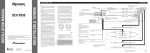
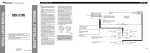
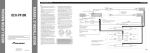
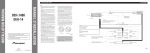
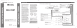
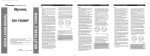
Connecting the Units
<ENGLISH>
When Connecting the Head Unit
Connecting the system
Head Unit
(sold separately)
Blue
3 m (9 ft. 10 in.)
When Connecting the Display with RCA Input Jacks
IP-BUS cable (supplied)
WARNING
• NEVER install the display in a location that enables the Driver to watch the DVD or
Video CD while Driving.
Yellow (front video output)
30-pin cable
3 m (9 ft. 10 in.)
Hide-away unit
Navigation system (AVIC-N3) display unit
(sold separately)
Yellow
• NEVER connect audio output (AUDIO OUT) to sold separately power amp.
IP BUS
Hide-away unit
Black
STAND ALONE
IP BUS
When installing
the Hide-away unit
in the boot, etc.,
the extension cable
(e.g. CD-SC300E)
(sold separately)
is required.
STAND ALONE
Yellow (front video output)
White (audio output (Left))
Red (audio output (Right))
Navigtion system (AVIC-N3) hide-away unit
(sold separately)
Red
Yellow
Black
9 cm (3-1/2 in.)
This product
Black
9 cm (3-1/2 in.)
This product
Not used.
Not used.
Blue
Yellow
Blue
16:9 Rear Seat Entertainment Display
(AVD-W6200) (sold separately)
AV-BUS cable (supplied)
White
3 m (9 ft. 10 in.) IP-BUS cable (supplied)
20 cm (7-7/8 in.)
RCA cable (supplied)
RCA cable (supplied)
Yellow (rear video output)
White (audio output (Left))
Red (audio output (Right))
2.7 m (8 ft. 10 in.)
6 m (19 ft. 8 in.)
6 m (19 ft. 8 in.)
STAND ALONE
Black
RCA cable (supplied)
2.7 m (8 ft. 10 in.)
6 m (19 ft. 8 in.)
This product
25 pin cable (supplied)
Depending on where you install,
this cable is not used.
Hide-away unit
IP BUS
20 cm (7-7/8 in.)
Black
Black
White
3 m (9 ft. 10 in.)
25 pin cable (supplied)
Depending on where you install,
this cable is not used.
To video input
To video input
VIDEO1 RCA audio input
(white, red)
9 cm (3-1/2 in.)
Black
20 cm (7-7/8 in.)
Black
VIDEO1 RCA video input
(yellow)
Display with RCA
input jacks
3 m (9 ft. 10 in.)
2.7 m (8 ft. 10 in.)
Black
Black
Hide-away unit
(supplied with AVD-W6200)
25 pin cable (supplied)
Depending on where you install,
this cable is not used.
VIDEO1 INPUT
To audio inputs
Display with RCA
input jacks
Connecting the Units
<ENGLISH>
When Using a Display Connected Rear Video Output
Connecting the Power Cord
This product’s rear video output is for connection of a display to enable passengers in the
rear seats to watch the DVD or Video CD.
Hide-away unit
WARNING
• NEVER install the display in a location that enables the Driver to watch the DVD or
Video CD while Driving.
• NEVER connect audio output (AUDIO OUT) to sold separately power amp.
Hide-away unit
IP BUS
STAND ALONE
Yellow (rear video output)
White (audio output (Left))
Red (audio output (Right))
Fuse resistor
Black
9 cm (3-1/2 in.)
This product
Not used.
Fuse resistor
Orange/white
To lighting switch terminal.
Fuse holder
(4 A)
Yellow
Y
To terminal always supplied with power
regardless of ignition switch position.
20 cm (7-7/8 in.)
RCA cable (supplied)
Black
2.7 m (8 ft. 10 in.)
6 m (19 ft. 8 in.)
25 pin cable (supplied)
Depending on where you install,
this cable is not used.
To video input
To audio inputs
Display with RCA
input jacks
Red
When using this product in STAND ALONE
mode, connect this cord to electric terminal
controlled by ignition switch (12 V DC) ON/OFF.
When using this product in IP BUS mode,
do not connect this cord.
Black (ground)
To vehicle (metal) body.
Installation
Note:
• Before making a final installation of the unit, temporarily connect the wiring to confirm that the
connections are correct and the system works
properly.
• Use only the parts included with the unit to ensure
proper installation. The use of unauthorized parts
can cause malfunctions.
• Consult with your nearest dealer if installation
requires the drilling of holes or other modifications of the vehicle.
• Install the unit where it does not get in the driver’s
way and cannot injure the passenger if there is a
sudden stop, like an emergency stop.
• Do not place the display (sold separately) in a
position where it will impede the driver’s visibility
or affect the operation of your vehicle’s air bags.
• The semiconductor laser will be damaged if it
overheats, so don’t install the unit anywhere hot
— for instance, near a heater outlet.
• If installation angle exceeds 30° from horizontal,
the unit might not give its optimum performance.
<ENGLISH>
• If the hide-away unit is installed under a front seat,
make sure it does not obstruct seat movement.
Route all leads and cords carefully around the sliding mechanism so they do not get caught or
pinched in the mechanism and cause a short circuit.
MODE Switch Setting
Before installing, use a pen tip or other thin,
pointed instrument to set the MODE Switch to
the appropriate position for the component you
are using it with.
IP BUS
DIN Front/Rear-mount
Insert the supplied extraction keys into the
unit, as shown in the figure, until they
click into place. Keeping the keys pressed
against the sides of the unit, pull the unit
out.
This unit can be properly installed either from “Front” (conventional DIN Front-mount) or
“Rear” (DIN Rear-mount installation, utilizing threaded screw holes at the sides of unit
chassis). For details, refer to the following illustrated installation methods.
Cover
Installation with the rubber bush
STAND ALONE
Dashboard
182
Installing the hide-away unit
53
Holder
After inserting the holder into the dashboard, then select the appropriate tabs
according to the thickness of the dashboard material and bend them.
(Install as firmly as possible using the
top and bottom tabs. To secure, bend
the tabs 90 degrees.)
DIN Rear-mount
1. Remove the frame.
Rubber bush
Screw
Car mat or chassis
Frame
Drill 4 to 4.5 mm (1/8 in.) diameter holes.
Frame
Hide-away unit
Bracket
Truss screw (5 × 8 mm)
Installation using the screw holes on the side of the unit
Thoroughly wipe off the surface before
affixing the velcro tape.
Velcro tape
(large) (hard)
Velcro tape
(large) (soft)
To remove the frame, extend top and bottom of the frame outwards in order to unlock it.
(When reattaching the frame, point the side with a groove downwards and attach it.)
• It becomes easy to remove the frame if the front panel is released.
2. Fastening the unit to the factory radio mounting bracket.
Select a position where the screw holes of the
bracket and the screw holes of the head unit
become aligned (are fitted), and tighten the
screws at 2 places on each side. Use either
truss screws (5 × 8 mm) or flush surface
screws (5 × 8 mm), depending on the shape of
the screw holes in the bracket.
Removing the unit
Car mat or chassis
Tapping screw (6 × 16 mm)
DIN Front-mount
Mounting with Velcro Tape
• When mounting the hide-away unit, make sure
none of the leads are trapped between the hideaway unit and the surrounding metalwork or fittings.
• Do not mount the hide-away unit near the heater
outlet, where it would be affected by heat, or near
the doors, where rainwater might splash onto it.
• Before drilling any mounting holes always check
behind where you want to drill the holes. Do not
drill into the gas line, brake line, electrical wiring
or other important parts.
• If the hide-away unit is installed in the passenger
compartment, anchor it securely so it does not
break free while the car is moving, and cause
injury or an accident.
Mounting with Brackets
Frame
Screw
To remove the frame, extend top and bottom of the frame outwards in order to unlock it.
(When reattaching the frame, point the side with a groove downwards and attach it.)
Dashboard or Console
• It becomes easy to remove the frame if the front panel is released.
Factory radio mounting
bracket
Raccordements des appareils
<FRANÇAIS>
• Assurez-vous que les câblages ne font pas
obstacle aux pièces mobiles du véhicule,
telles que le levier des vitesses, le frein à
main ou le mécanisme de coulissement
des sièges.
• Ne court-circuitez pas les fils car le
circuit de protection ne fonctionnerait
plus correctement.
• N’installez pas cet écran (vendue
séparément) dans un endroit où il
risque de (i) masquer la vision du
conducteur, (ii) gêner l’utilisation
d’un système du véhicule ou d’un
dispositif de sécurité, comme par
exemple, un coussin de sécurité
gonflable ou le bouton des feux de
détresse, ou (iii) empêcher le
conducteur de conduire le véhicule
en toute sécurité.
OF
OF
Position ACC
F
O
STAR
• Une situation très dangereuse pourrait se
présenter si le fil de l’écran devait
s’enrouler autour de la colonne de
direction ou du levier des vitesses. Veillez
à installer l’écran (vendue séparément)
de telle sorte que rien ne fasse obstacle à
la conduite.
O
N
• Ne forez pas un orifice vers le
compartiment du moteur afin de
raccorder le fil jaune de l’appareil sur la
batterie du véhicule car les vibrations du
moteur pourraient à la longue abîmer
l’isolation du fil au point de passage
entre l’habitable et le compartiment du
moteur. Veillez tout particulièrement à
bien immobiliser le fil à ce point.
ACC
STAR
• Immobilisez toutes les câblages avec des
serre-fils ou du ruban isolant. Ne laissez
aucun conducteur à nu.
F
N
• Dans certains états ou pays il peut être
illégal même pour des personnes autres
que le conducteur de regarder des
images sur un écran à l’intérieur d’un
véhicule. Quand cette réglementation est
applicable, elle doit être respectée, et les
fonctions DVD de cet appareil ne doivent
pas être utilisées.
CAUTION:
• PIONEER ne vous recommande pas
d’installer ou d’entretenir vous-même
cet écran (vendue séparément), car ces
travaux peuvent présenter un risque
d’électrocution ou d’autres dangers.
Confiez tous les travaux d’installation et
d’entretien de votre écran au personnel
de service Pioneer agréé.
• Cette unité ne peut pas être installée dans un
véhicule dont le contacteur d’allumage n’a pas
de position ACC (accessoire).
T
AVERTISSEMENT:
• Pour éviter tout risque d’accident, et
toute infraction aux lois en vigueur,
l’affichage à l’avant d’image de DVD ou
de télévision (vendue séparément) ne doit
jamais être employé tandis que le
véhicule roule. Par ailleurs, les écrans
arrière ne doivent jamais se trouver
placés de manière à distraire l’attention
du conducteur.
• Cet appareil est destiné aux véhicules avec une
batterie de 12 V, avec pôle négatif à la masse. Avant
de l’installer dans un véhicule de loisir, un camion
ou un car, vérifier la tension de la batterie.
• Afin d’éviter tout risque de court-circuit, débrancher
le câble de la borne négative ≠ de la batterie avant
de commencer la pose.
• Pour le raccordement des câbles de l’amplificateur
de puissance et des autres appareils, se reporter au
manuel de l’utilisateur et procéder comme il est
indiqué.
• Fixer les câbles au moyen de colliers ou de
morceaux de ruban adhésif. Pour protéger le câblage,
enrouler la bande adhésive autour des câbles à
l’endroit où ceux-ci sont placés contre les parties
métalliques.
• Acheminer et fixer tout le câblage de telle sorte qu’il
ne touche pas les pièces mobiles, comme le levier de
changement de vitesse, le frein à main et les rails des
sièges. Ne pas acheminer les câbles dans des
endroits qui peuvent devenir chauds, comme près de
la sortie de radiateur. Si l’isolation des câbles fond
ou est se déchire, il existe un danger de court-circuit
des câbles avec la carrosserie du véhicule.
• Ne pas faire passer le conducteur jaune dans le
compartiment moteur par un trou pour le connecter
avec la batterie. Cela pourrait endommager sa gaine
d’isolation et provoquer un grave court-circuit.
• Ne pas court-circuiter les conducteurs. Dans le cas
contraire, le circuit de protection risque de ne pas
fonctionner.
• Ne jamais alimenter un autre appareil par un
branchement sur le câble d’alimentation de celui-ci.
Le courant qui circulerait dans ce conducteur
pourrait dépasser la capacité du conducteur et
entraîner une élévation anormale de température.
• Remplacez le fusible par un fusible ayant le calibre
prescrit pour le porte-fusible.
• Pour éviter une connexion incorrecte, le côté entrée
du connecteur IP-BUS est bleu et même couleur
correctement.
T
Remarque:
Aucune position ACC
• Le conducteur noir est le fil de masse. Veillez à
relier ce conducteur à une masse qui ne soit pas la
masse d’un appareil gros consommateur d’énergie
tel qu’un amplificateur de puissance.
En effet, si vous utilisez la même masse pour
plusieurs appareils et si ces masses sont supprimées
par un défaut de contact, l’endommagement de
l’appareil, voire un incendie sont possibles.
• Les câbles de ce produit et ceux d’autres
produits peuvent fort bien ne pas être de la
même couleur bien que remplissant la même
fonction. Pour relier ce produit à un autre produit,
utilisez le manuel de chacun et effectuez les raccordements en ne tenant compte que de la fonction de chaque câble.
Raccordements des appareils
<FRANÇAIS>
Raccordement du système
Lors du raccordement à l’élément central
Câble à 30 broches
3m
Lors de l’installation
de l’appareil déporté
dans le coffre, etc.,
vous devez utiliser
un cordon
prolongateur
(CD-SC300E, par ex.)
(vendu séparément).
AVERTISSEMENT
Câble IP-BUS (fourni)
• Veillez à ce que l’écran NE SOIT PAS installé en un endroit tel que le conducteur puisse
observer les images fournies par le DVD ou le Video CD tout en conduisant.
• NE raccordez JAMAIS la sortie audio (AUDIO OUT) à un amplificateur de puissance
vendu séparément.
Jaune (sortie vidéo avant)
Appareil d’affichage du système de navigation
(AVIC-N3) (vendu séparément)
Jaune
3m
Élément central
(vendu séparément)
Bleu
Lors du raccordement à l’écran muni de prises d’entrée Cinch (RCA)
Appareil déporté
IP BUS
Appareil déporté
Noir
STAND ALONE
IP BUS
Appareil déporté du système de navigationn (AVIC-N3)
(vendu séparément)
Rouge
Jaune
Noir
9 cm
Bleu
Jaune
Affichage récréatif 16:9 pour
les sièges arrière (AV-W6200)
(vendu séparément)
Bleu
Cet appareil
Câble IP-BUS (fourni)
Non utilisé.
Non utilisé.
20 cm
6m
Cet appareil
Câble à fiches Cinch
(RCA) (fourni)
Noir
2,7 m
6m
Appareil déporté
STAND ALONE
Noir
Blanc 3 m
Noir
Vers l’entrée vidéo
Noir
Appareil déporté
(fourni avec le AVD-W6200)
Câble à 25 broches (fourni)
En fonction de l’emplacement de l’installation,
il se peut que ce câble ne soit pas nécessaire.
2,7 m
Câble à 25 broches (fourni)
En fonction de l’emplacement de l’installation,
il se peut que ce câble ne soit pas nécessaire.
Vers l’entrée vidéo
Vers les entrées audio
3m
Écran muni de prises
d’entrée Cinch (RCA)
2,7 m
Noir
Noir
Câble à fiches Cinch
(RCA) (fourni)
6m
Entrée vidéo Cinch (RCA)
VIDEO1 (jaune)
20 cm
Noir
20 cm
Câble à 25 broches (fourni)
En fonction de l’emplacement de l’installation,
il se peut que ce câble ne soit pas nécessaire.
Entrée audio Cinch (RCA)
VIDEO1 (blanc, rouge)
9 cm
Cet appareil
Câble RCA (fourni)
Jaune (sortie vidéo arrière)
Blanc (sortie audio (gauche))
Rouge (sortie audio (droite))
IP BUS
Noir
9 cm
Câble AV-BUS (fourni)
Blanc
3m
STAND ALONE
Jaune (sortie vidéo avant)
Blanc (sortie audio (gauche))
Rouge (sortie audio (droite))
VIDEO1 INPUT
Écran muni de prises
d’entrée Cinch (RCA)
Raccordements des appareils
<FRANÇAIS>
Lors de l’utilisation d’un écran raccordé à la sortie vidéo arrière
Branchement du cordon d’alimentation
La sortie vidéo arrière de cet appareil est destinée à un écran placé de telle sorte que les passagers arrière puissent regarder les images fournies par un DVD ou un Video CD.
Appareil déporté
AVERTISSEMENT
• Veillez à ce que l’écran NE SOIT PAS installé en un endroit tel que le conducteur puisse
observer les images fournies par le DVD ou le Video CD tout en conduisant.
• NE raccordez JAMAIS la sortie audio (AUDIO OUT) à un amplificateur de puissance
vendu séparément.
Appareil déporté
IP BUS
STAND ALONE
Jaune (sortie vidéo arrière)
Blanc (sortie audio (gauche))
Rouge (sortie audio (droite))
Résistance fusible
Noir
9 cm
Cet appareil
Rouge
Lors de l’utilisation cet appareil en mode
STAND ALONE, connectez ce cordon à une
borne dont l’alimentation est commandée par
la clé de contact (12 V CC) ON/OFF. Lors de
l’utilisation de cet appareil en mode IP BUS,
ne connectez pas ce cordon.
Non utilisé.
20 cm
Câble à fiches Cinch
(RCA) (fourni)
6m
Noir
2,7 m
Câble à 25 broches (fourni)
En fonction de l’emplacement de l’installation,
il se peut que ce câble ne soit pas nécessaire.
Vers l’entrée vidéo
Vers les entrées audio
Display with RCA
input jacks
Résistance fusible
Orange/blanc
Vers la borne du contacteur d’éclairage.
Porte-fusible
(4 A)
Jaune
Vers une borne alimentée en permanence
indépendamment de la clé de contact.
Noir (masse)
Fil de masse vers un élément en métal
apparent de la voiture.
Installation
Remarque:
• Avant d’effectuer l’installation définitive, reliez
provisoirement les appareils entre eux pour vous
assurer qu’ils fonctionnent correctement, individuellement et ensemble.
• Pour obtenir une bonne installation, n’utiliser que
les pièces de l’appareil. L’utilisation de pièces non
prévues risque de causer un mauvais fonctionnement.
• Consulter le concessionnaire le plus proche si l’installation nécessite le percement de trous ou toute
autre modification du véhicule.
• Installer l’appareil à un endroit où il ne gêne pas le
conducteur et où il ne peut pas blesser les passagers en cas d’arrêt brusque, comme pendant un
arrêt d’urgence.
• Ne placez pas l’écran (vendue séparément)dans
une position où il peut gêner la visibilité du conducteur ou affecter le bon fonctionnement des sacs
gonflables de protection.
• Le laser semiconducteur sera endommagé en cas
de réchauffement excessif. Dans ce cas ne pas
installer l’appareil dans un endroit présentant une
température élevée, tel que sortie de chauffage.
• L’angle de l’installation, ne doit pas dépasser 30°
par rapport à l’horizontale, faute de quoi l’unité ne
fournira pas ses performances optimales.
<FRANÇAIS>
•
Si l’appareil déporté est installé sous un des
sièges avant, veillez à ce qu’il ne gêne pas le
mouvement du siège. Faites soigneusement
cheminer les conducteurs et les cordons autour
des rails du siège de telle sorte qu’ils ne puissent
pas être agrippés par les rails et provoquer un
court-circuit.
Réglage du sélecteur MODE
Avant l’installation, utilisez la pointe d’un
stylo à bille ou tout autre instrument pointu et
fin pour placer le sélecteur MODE sur la position appropriée compte tenu de l’appareil que
vous utilisez conjointement.
IP BUS
STAND ALONE
Montage DIN avant/arrière
Cet appareil peut être monté aisement, ou par le procédé de montage avant DIN (normal), ou
bien par le procédé de montage arrière DIN, en utilisant les orifices de vis sur les côtés du châssis de l’appareil. Pour les détails veuillez vous référer aux méthodes de montage illustrées qui
suivent.
Tableau de bord
53
Support
Après avoir introduit le support dans le tableau
de bord, sélectíonnez les languettes appropriées
en fonction de l’épaisseur du matériau du tableau
de bord et courbez-les.
(Assurez le maintien aussi solidement que possible
en utilisant les languettes inférieures et supérieures.
Cela fait, courbez les languettes de 90 degrés.)
Montage DIN arrière
Installation en utilisant les trous de vis sur les côtés de l’appareil
Cadre
Fixation avec la bande Velcro
Cadre
Pour enlever le cadre, tirez le haut et le bas du cadre vers l’extérieur pour le débloquer.
(Pour remettre le cadre en place, diriger le côté avec la rainure vers le bas et fixez le cadre.)
Bande Velcro
(grande) (rugueux)
Bande Velcro
(grande) (doux)
•
•
•
• Il devient facile d’enlever le cadre si la face avant est enlevée.
2. Fixation de l’appareil au support pour le montage de la radio installée par le
constructeur.
Dépose de l’unite
Moquette ou châssis
du véhicule
Equerre
Vis à tête bombée (5 × 8 mm)
1. Enlever le cadre.
Bague en caoutchouc
Vis
Appareil déporté
Lors de l’installation de l’appareil déporté, veillez
à ce qu’aucun conducteur ne soit prisonnier entre
l’appareil déporté et les pièces métalliques et
accessoires qui l’entourent.
N’installez pas l’appareil déporté à proximité
d’une bouche de chauffage, en un endroit où son
fonctionnement puisse être perturbé par la
chaleur, ni près des portières, c’est-à-dire là où
l’eau de pluie pourrait l’atteindre.
Avant d’effectuer un perçage requis par l’installation de l’appareil, assurez-vous que vous pouvez
le faire sans danger pour les câbles, canalisations,
flexibles, etc., qui sont placés derrière le panneau
que vous devez percer.
Si l’appareil déporté est installé dans l’habitacle,
assurez-vous que sa fixation est solide de manière
qu’il ne puisse pas se libérer pendant le déplacement du véhicule, et provoquer ainsi une blessure
ou un accident.
Vis autotaraudeuse (6 × 16 mm)
Installation avec une bague en caoutchouc
Nettoyez soigneusement la surface
avant de poser la bande Velcro.
•
Fixation avec les équerres
Couvercle
Montage DIN avant
182
Installation de l’appareil déporté
Insérer les clés d’extraction fournis dans
l’unité, comme indiqué dans la figure,
jusqu’à ce qu’elles s’enclenchent en position. En maintenant ces clés pressées contre les côtés de l’unité, retirer l’unité.
Choisir la position selon laquelle les orifices
de vis du support et ceux des vis de l’appareil
principal sont alignés (correspondent) et serrer
les vis sur 2 endroits de chaque côté. Utiliser
l’une des vis de serrage (5 × 8 mm) ou les ves
à tête plate (5 × 8 mm), selon le forme des
trous de vis sur le support.
Cadre
Vis
Tableau de bord ou console
Pour enlever le cadre, tirez le haut et le bas du cadre vers l’extérieur pour le débloquer.
(Pour remettre le cadre en place, diriger le côté avec la rainure vers le bas et fixez le cadre.)
• Il devient facile d’enlever le cadre si la face avant est enlevée.
Support pour le montage de la radio
Moquette ou châssis du véhicule
Percez des trous de 4 à 4,5 mm de diamètre.