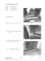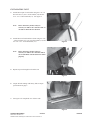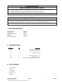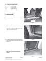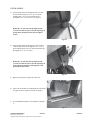
1
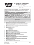
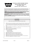
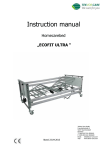
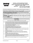
INSTALLATION INSTRUCTIONS ROCK SLIDER KIT Part Number: 76600 Application: 2006-2008 Arctic Cat Prowler XT 650 4x4 Auto, XT 650 4x4 Auto M4 and XTX 700 H1 LE Your safety, and the safety of others, is very important. To help you make informed decisions about safety, we have provided installation and operating instructions and other information on labels and in this guide. This information alerts you to potential hazards that could hurt you or others. It is not possible to warn you about all potential hazards associated with this product, you must use your own good judgment. CARELESS INSTALLATION AND OPERATION CAN RESULT IN SERIOUS INJURY OR EQUIPMENT DAMAGE. READ AND UNDERSTAND ALL SAFETY PRECAUTIONS AND OPERATING INSTRUCTIONS BEFORE INSTALLING AND OPERATING THIS PRODUCT. This guide identifies potential hazards and has important safety messages that help you and others avoid personal injury or death. WARNING and CAUTION are signal words that identify the level of hazard. These signal words mean: WARNING signals a hazard that could cause serious injury or death, if you do not follow recommendations. CAUTION signals a hazard that may cause minor to moderate injury, if you do not follow recommendations. This guide uses NOTICE to call attention to important mechanical information, and Note: to emphasize genera l information worthy of special attention. WARNING INJURY HAZARD Failure to observe these instructions could lead to severe injury or death. Always use extreme caution when drilling on any vehicle. Make sure that all fuel lines, brake lines, electrical wires, and other objects are not punctured or damaged when / if drilling on the vehicle. Thoroughly inspect the area to be drilled (on both sides of material) prior to drilling, and relocate any objects that may be damaged. Failure to inspect the area to be drilled may result in vehicle damage, electrical shock, fire or personal injury. Always wear safety glasses when installing this kit. A drilling operation will cause flying metal chips. Flying chips can cause eye injury. Always use extreme caution when cutting and trimming during fitting. Always remove jewelry and wear eye protection. Never lean over battery while making connections. Never route electrical cables: Across any sharp edges. Through or near moving parts. Near parts that become hot. Always insulate and protect all exposed wiring and electrical terminals. Always install terminal boots as directed in installation instructions. Always use appropriate and adequate care in lifting components into place. Always insure components will remain secure during installation and operation. Always tighten all nuts and bolts securely, per the installation and operation. Always perform regular inspections and maintenance on the winch, winch mount and related hardware. Never operate this WARN product with damaged or missing parts. WARN INDUSTRIES PAGE 1 ©2007 Warn Industries, Inc. WARN® and the WARN logo are trademarks of Warn Industries Inc. 76599A0 Caution Mo ving P ar ts Entanglement Hazard Moving Par arts Failure tto o obser o minor or moderat e injur observve these instructions could lead tto moderate injuryy. Always take time to fully read and understand the installation and Operations Guide included with this product. Never operate this product if you are under 16 years of age. Never operate this product when under the influence of drugs, alcohol or medications. Read installation and operating instructions thoroughly. Notice Equipment Damage Always refer to the Installation and Specification Guide, supplied in the winch kit, for all wiring schematics and specific details on how to wire this WARN product to your vehicle. Read installation and operating instructions thoroughly. I. TABLE OF CONTENTS Parts List Tools Required Torque Specifications Installation Maintenance/Care page 2 page 2 page 3 page 3-4 page 5 II. PARTS LIST Reference Number A1 A2 Qty 1 1 Description Left Rock Slider Right Rock Slider B1 12 Factory Bolts C1 C2 C3 6 6 6 5/16 - 18 Lock Nut 5/16 Flat Washer 5/16 - 18 x .75 Hex Head Bolt III. TOOLS REQUIRED - TB-45 Torx drive - 1/2” wrench - 1/2” socket - Socket wrench - 5/16” drill bit - Drill WARN INDUSTRIES PAGE 2 ©2007 Warn Industries, Inc. WARN® and the WARN logo are trademarks of Warn Industries Inc. 76599A0 IV. TORQUE SPECIFICATIONS 1/4 (M6) 5/16 (M8) 3/8 (M10) 7/16 (M12) 1/2 (M14) 8 lb. ft. (10.8 N-m) 17 lb. ft. (12.5 N-m) 30 lb. ft. (40.7 N-m) 50 lb. ft. (67.8 N-m) 75 lb. ft. (101.7 N-m) V. INSTALLATION Remove 1. Remove factory bolts shown in Figure 1, using torx drive. Note: Figure 1 Factory bolts removed in this step will be reused. Figure 2 2. Assemble rock sliders reusing factory bolts that were removed in step one. See Figures 2 and 3. Note: Do not tighten bolts at this time. Figure 3 WARN INDUSTRIES PAGE 3 ©2007 Warn Industries, Inc. WARN® and the WARN logo are trademarks of Warn Industries Inc. 76599A0 INSTALLATION CONT. 3. Attach bottom part of rear bracket using one 5/16 - 18 hex lock nut (C1), one 5/16 flat washer (C2) and one 5/16 - 18 x .75 hex head bolt (C3). See Figure 4. Note: 4. Attach bottom of front bracket to frame using two 5/16 - 18 hex lock nuts (C1), two 5/16 flat washers (C2) and two 5/16 - 18 x .75 hex head bolts (C3). Note: 5. Due to the factory frame, it may be necessary to drill a 5/16” clearance hole on one side to attach the rear bracket. Figure 4 Due to the factory frame, it may be necessary to drill a 5/16” clearance hole in one or both holes of front bracket to attach properly. Repeat steps one through four for other side. Figure 5 6. Torque all bolts starting with factory bolts to torque specifications on page 2. 7. See Figure 6 for completed view of driver side. Figure 6 WARN INDUSTRIES PAGE 4 ©2007 Warn Industries, Inc. WARN® and the WARN logo are trademarks of Warn Industries Inc. 76599A0 WARNING READ THE VEHICLE’S OPERATOR MANUAL AND ALL WARNING LABELS PRIOR TO OPERATION OF ATV. THE ROCK SLIDER INSTALLATION IS NOW COMPLETE. PROCEED TO SECTION TITLED “MAINTENANCE/CARE”. WARNING FAILURE TO SECURELY TIGHTEN ALL BOLTS ON THE ROCK SLIDERS CAN RESULT IN PRODUCT FAILURE WHICH MAY RESULT IN VEHICLE DAMAGE AND OPERATOR INJURY OR DEATH. DOUBLE CHECK THAT ALL BOLTS ARE SECURELY TIGHTENED PRIOR TO USE. VI. MAINTENANCE/CARE 1. Inspect all parts and related hardware prior to each use. Replace all hardware that appears rusted or deformed. 2. Inspect all bolts on the rock sliders and related hardware prior to each use. Tighten all bolts that appear to be loose. Stripped, fractured, or bent bolts or nuts need to be replaced. WARNING PERFORM REGULAR INSPECTIONS ON THE ROCK SLIDERS AND RELATED HARDWARE. NEVER OPERATE THE ATV WITH DAMAGED OR MISSING PARTS RELATING TO THE ROCK SLIDERS. FAILURE TO FOLLOW THIS WARNING MAY CAUSE VEHICLE DAMAGE AND OPERATOR INJURY OR DEATH. WARN INDUSTRIES PAGE 5 ©2007 Warn Industries, Inc. WARN® and the WARN logo are trademarks of Warn Industries Inc. 76599A0 INSTALLATION DE MONTAGE KIT DE PROTECTIONS LATÉRALES (ROCK SLIDER) Part Number: 76600 Méthode d’application: 2006-2008 Arctic Cat Prowler XT 650 4x4 Auto, XT 650 4x4 Auto M4 and XTX 700 H1 LE Votre sécurité et celle des autres est très importante. Afin de vous permettre de prendre des décisions éclairées dans le domaine de la sécurité, nous vous avons fourni des instructions relatives à l’installation et à l’utilisation du produit ainsi que d’autres informations figurant sur des étiquettes et dans ce guide. Ces informations attirent l’attention sur les risques de danger pouvant vous affecter ainsi qu’autrui. Nous ne sommes pas en mesure de vous mettre en garde contre tous les dangers potentiels associés à ce produit. Il vous incombe par conséquent de faire preuve de jugement. TOUTE INSTALLATION OU UTILISATION IMPRUDENTE PEUT ENTRAÎNER DES BLESSURES GRAVES OU ENDOMMAGER L’ÉQUIPEMENT. PRENEZ SOIN DE LIRE ET DE BIEN ASSIMILER LES CONSIGNES DE SÉCURITÉ ET D’UTILISATION DU PRODUIT AVANT DE L’INSTALLER ET DE L’UTILISER. Ce guide identifie les dangers potentiels et comporte des consignes de sécurité importantes qui permettent à vous et à autrui d’éviter les risques de blessures graves ou de mort. Les termes AVERTISSEMENT et MISE EN GARDE sont des indicateurs du niveau de danger. Signification des indicateurs : Le terme consignes. AVERTISSEMENT souligne un danger potentiel qui peut entraîner des blessures graves ou la mort si vous ne suivez pas les Le terme MISE EN GARDE souligne un danger potentiel susceptible d’entraîner des blessures mineures ou modérées si vous ne suivez pas les consignes. Ce guide utilise le terme AVIS pour attirer votre attention sur des informations mécaniques importantes, et le terme Remarque : pour souligner des informations générales qui méritent une attention particulière. AVERTISSEMENT RISQUES DE BLESSURES Le non-respect des instructions peut entraîner des blessures graves, voire mortelles. Faites toujours extrêmement attention lorsque vous percez la carrosserie d’un véhicule. Veillez à ne pas perforer ni endommager les conduites de carburant, les conduites de frein, le câblage électrique ou tout autre objet lorsque vous percez. Inspectez endommagés. Le fait de ne pas inspecter l’emplacement peut finir par endommager le véhicule, entraîner un choc électrique, un incendie ou des blessures. Portez toujours des lunettes de protection lors de l’installation du kit. Des éclats métalliques sont projetés durant le perçage.Ces éclats peuvent causer des lésions oculaires. Faites toujours très attention lorsque vous découpez ou taillez. Retirez toujours les bijoux et portez des lunettes de sécurité. Ne vous penchez jamais au-dessus de la batterie en procédant aux connexions. Ne faites jamais passer des câbles électriques : Sur des bords tranchants. Par des pièces mobiles ou à proximité. À proximité de pièces pouvant devenir chaudes. Installez toujours les capuchons de borne de la manière indiquée dans les instructions d’installation. Faites toujours attention lorsque vous déplacez des composants. Assurez-vous toujours que les composants sont bien fixés durant l’installation et l’utilisation. Serrez toujours bien les écrous et les boulons conformément aux instructions d’installation et d’utilisation. Effectuez toujours régulièrement les inspections et l’entretien du treuil, de son kit de montage et du matériel de montage connexe. Ne faites jamais fonctionner ce produit WARN avec des pièces endommagées ou manquantes. WARN INDUSTRIES PAGE 1 ©2007 Warn Industries, Inc. WARN® and the WARN logo are trademarks of Warn Industries Inc. 76599A0 MISE EN GARDE Danger de happement par des pièces mobiles Le non-respect des instructions peut entraîner des blessures mineures ou modérées. Prenez toujours le temps de bien lire et comprendre le manuel d’installation et d’utilisation inclus avec ce produit. Les personnes âgées de moins de 16 ans ne doivent jamais faire fonctionner ce produit. Ne faites jamais fonctionner ce produit sous l’effet de drogues, de l’alcool ou de médicaments. Veuillez lire attentivement les instructions concernant l’installation et l’utilisation. AVIS Équipement endommagé Reportez-vous toujours au Guide d’installation et de spécification, fourni dans le kit de treuil, pour tous les schémas de câblage et des informations détaillées concernant la façon de brancher ce produit WARN sur votre véhicule. Veuillez lire attentivement les instructions concernant l’installation et l’utilisation. I. TABLE DES MATIÈRES Liste Des Pieces Outils Requis Couples De Serrage Installation Maintence/Entretien page page page page page 2 2 3 3-4 5 II. LISTE DES PIÈCES Référence A1 A2 Qté 1 1 Description Protection latérale gauche Protection latérale droite B1 12 Boulons d’origine C1 C2 C3 6 6 6 Écrou de blocage 5/16 - 18 Rondelle plate 5/16 Boulon à tête hexagonale 5/16 - 18 x 0,75 III. OUTILS REQUIS - Clé Torx TB-45 Clé 1/2 po Douille 1/2 po Clé à douille Mèche 5/16 po Perceuse WARN INDUSTRIES PAGE 2 ©2007 Warn Industries, Inc. WARN® and the WARN logo are trademarks of Warn Industries Inc. - 76599A0 IV. COUPLES DE SERRAGE 1/4 5/16 3/8 7/16 1/2 10,8 N-m (8 pi-lb) 12,5 N-m (8 pi-lb) 40,7 N-m (30 pi-lb) 67,8 N-m (50 pi-lb) 101,7 N-m (75 pi-lb) V. INSTALLATION 1. Retirez les boulons d’origine montrés à la figure 1 à l’aide de la clé Torx. Remove Figure 1 Remarque : Les boulons d’origine enlevés à cette étape seront réutilisés plus tard. 2. Assemblez les protections latérales en réutilisant les boulons d’origine enlevés à la première étape. Voir les figures 2 et 3. Figure 2 Remarque : Ne serrez pas les boulons pour l’instant. Figure 3 WARN INDUSTRIES PAGE 3 ©2007 Warn Industries, Inc. WARN® and the WARN logo are trademarks of Warn Industries Inc. 76599A0 INSTALLATION 3. Fixez la partie inférieure du support arrière à l’aide d’un écrou de blocage hex 5/16 - 18 (C1), d’une rondelle plate 5/16 (C2) et d’un boulon à tête hexagonale 5/16 - 18 x 0,75 (C3). Voir figure 4. Remarque : À cause du cadre d’origine, il peut s’avérer nécessaire de percer un trou de passage de 5/16 po d’un côté pour pouvoir fixer le support arrière. Figure 4 4. Fixez la partie inférieure du support avant au cadre à l’aide de deux écrous de blocage hex 5/16 - 18 (C1), deux rondelles plates 5/16 (C2) et deux boulons à tête hexagonale 5/16 - 18 x 0,75 (C3). Remarque : À cause du cadre d’origine, il peut s’avérer nécessaire de percer un trou de passage de 5/16 po dans un ou deux trous du support avant pour pouvoir bien le fixer. Figure 5 5. Répétez les étapes une à quatre de l’autre côté. 6. Serrez tous les boulons en commençant par les boulons d’origine selon les couples de serrage de la page 2. 7. Voir l’installation terminée côté conducteur à la figure 6. Figure 6 WARN INDUSTRIES PAGE 4 ©2007 Warn Industries, Inc. WARN® and the WARN logo are trademarks of Warn Industries Inc. 76599A0 AVERTISSEMENT LISEZ LE MANUEL DE L’UTILISATEUR DU VTT AINSI QUE TOUTES LES ÉTIQUETTES D’AVERTISSEMENT AVANT TOUTE UTILISATION DU VÉHICULE. L’INSTALLATION DES PROTECTIONS LATÉRALES EST À PRÉSENT TERMINÉE. PASSEZ À LA SECTION INTITULÉE « MAINTENANCE/ENTRETIEN ». AVERTISSEMENT LE FAIT DE NE PAS SERRER SOLIDEMENT TOUS LES BOULONS DES PROTECTIONS LATÉRALES PEUT ENTRAÎNER UNE DÉFAILLANCE DU PRODUIT, CE QUI PEUT ENDOMMAGER LE VÉHICULE ET PROVOQUER DES BLESSURES OU LA MORT DE L’OPÉRATEUR. AVANT TOUTE UTILISATION, ASSUREZ-VOUS QUE TOUTES LES FIXATIONS SONT BIEN SERRÉES. VI. MAINTENANCE/ENTRETIEN 1. Inspectez toutes les pièces et le matériel de montage connexe avant toute utilisation. Remplacez tout matériel qui semble rouillé ou déformé. 2. Inspectez tous les boulons des protections latérales et le matériel de montage connexe avant toute utilisation. Resserrez tous les boulons qui en ont besoin. Les écrous et boulons foirés, fracturés ou tordus doivent être remplacés. AVERTISSEMENT INSPECTEZ RÉGULIÈREMENT LES PROTECTIONS LATÉRALES ET LE MATÉRIEL DE MONTAGE CONNEXE. NE FAITES JAMAIS FONCTIONNER LE VTT AVEC DES PIÈCES ENDOMMAGÉES OU MANQUANTES LIÉES AUX PROTECTIONS LATÉRALES. LE FAIT DE NE PAS RESPECTER CET AVERTISSEMENT PEUT FINIR PAR ENDOMMAGER LE VÉHICULE OU PROVOQUER DES BLESSURES GRAVES OU LA MORT DE L’OPÉRATEUR. WARN INDUSTRIES PAGE 5 ©2007 Warn Industries, Inc. WARN® and the WARN logo are trademarks of Warn Industries Inc. 76599A0