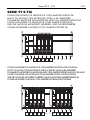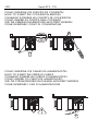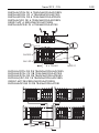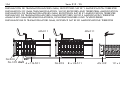
1
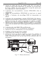
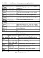
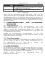
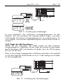
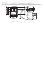
PS PROGRAMMER
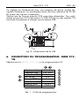
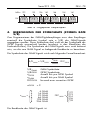
Serie 912-TQ
1
ESP
ESPAÑOL . . . . . . . .3
ENG
ENGLISH . . . . . . .19
FRA
FRANÇAIS . . . . . .35
POR
PORTUGUES . . . . .51
DEU
DEUTSCH . . . . . . .67
ITA
ITALIANO
ESP
ANEXO . . . . . . . .99
ENG
ANNEX . . . . . . . .99
FRA
ANNEXE . . . . . . .99
POR
ANEXO . . . . . . . .99
DEU
ANHANG
ITA
ANNESSI . . . . . . .99
. . . . . .83
. . . . . .99
2
Índice
ESP - 3
ÍNDICE
SERIE 912 - TQ
1 INSTRUCCIONES DE SEGURIDAD ..............................................5
2 DESCRIPCIÓN ..........................................................................6
3 PLAN DE FRECUENCIAS ............................................................8
4 CÁLCULO DE LA TASA DE SÍMBOLOS (SYMBOL RATE S/R) ..........9
5 INSTALACIÓN ........................................................................10
6 DESCRIPCIÓN DEL PROGRAMADOR: SERIE 912 - TQ ................11
7 ENVÍO DE DATOS AL TRANSMODULADOR TQ .........................13
8 COPIA DE DATOS ...................................................................13
9 LECTURA DE DATOS................................................................13
10 AJUSTE DE NIVELES ................................................................14
11 SOLUCIÓN DE POSIBLES ANOMALÍAS.....................................16
ANEXO
1 INSTALACIÓN SERIE 912 - TQ ...............................................101
2 PLAN DE FRECUENCIAS ESTÁNDAR.......................................105
3 TASA DE SÍMBOLOS (S/R) .....................................................106
4 - ESP
Manual de instalación y programación
Serie 912 - TQ
ESP - 5
SERIE 912 - TQ
1.
INSTRUCCIONES DE SEGURIDAD
Realice todas las conexiones de FI, RF y alimentación antes de conectar
los equipos a la red eléctrica.
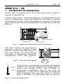
Para cumplir las normas de seguridad, la instalación eléctrica debe estar
protegida por un disyuntor diferencial. Para efectuar la conexión del
alimentador a la red, utilice una regleta de conexiones. Es necesario
conectar el cable verde y amarillo del alimentador a la toma de tierra de
la red eléctrica.
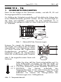
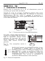
230 V
VERDE/AMARILLO
Fig. 1 - Conexión de la toma de tierra del alimentador
No quite las cubiertas de los equipos
mientras continúan conectados a la red
eléctrica. Toda reparación debe ser
realizada por personal del servicio
técnico autorizado. La manipulación
interna de los equipos anula toda
garantía.
Fig. 2 - No manipular conectado
230 V
Verifique que el equipo esté correctamente ventilado.En
caso de instalación en cofre, utilice el cofre con ventilador
CV-001 (cód. 9120068) o el cofre CP-710 (cód.
+ 45 °C
9050041), junto con el ventilador VE-500 (cód.
-- 10 °C 9050043). Un equipo trabajando fuera de su rango de
temperatura (-5 a +50°C) puede quedar dañado
irremediablemente. No bloquee o cubra las ranuras de
ventilación del alimentador ni del cofre.
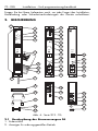
Fig. 3 - Rango de temperaturas
6 - ESP
Manual de instalación y programación
Consulte a su proveedor si tiene alguna duda respecto a la instalación,
operación o requisitos de seguridad de los equipos.
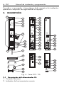
2.
DESCRIPCIÓN
6
10
1
11
2
ON
OFF
ON
3
OVL.
ERROR
PROGRAM MODE
4
12
13
READ
IN
OK
14
INPUT
230 V~ ±20%
50/60Hz
QPSK/QAM
OK
912
5
OUTPUT
FA-203
TQ-501
OUT
OK
8
OUTPUT
I
5
V
2.2 A
5
V
2.2 A
13 V
1.3 A
13
V
1.3
A
30
V
0.35
A
18
19
- 15dB
29
30
PA-102
ON
- 10dB
- 0dB
- 0dB
42
6
912
17
5v
5v
13
13
30 v
V
15
16
912
31
32
20
33
21
34
22
35
7
SAT
IN
9
+13V
350mA max
23
SAT
OUT
26
24
LNB
EXT
ON
36
OFF
TEST
27
25
28
39
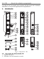
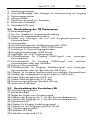
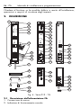
Fig. 4 - Serie 912 - TQ
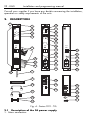
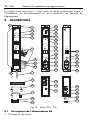
2.1 Descripción del alimentador FA
1- Conexión de masa
2- Indicador de funcionamiento correcto
-30dB
OUT
37
38
40
41
Serie 912 - TQ
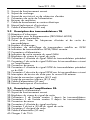
3456789-
ESP - 7
Indicador de sobrecarga
Indicador de cortocircuito o subtensión de entrada
Conector de salida de alimentación
Ranuras de ventilación
Cable de conexión a la red eléctrica
Hoja de características técnicas
Cable de alimentación (120 mm)
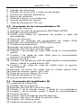
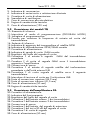
2.2 Descripción de los transmoduladores TQ
10- Receptor de infrarrojos
11- Interruptor de modo de programación (PROGRAM MODE)
12- Indicador de programación
13- Casillas para anotar las frecuencias de entrada y salida del
transmodulador
14- Emisor de infrarrojos
15- Indicador de enganche del transpondedor de satélite QPSK
16- Indicador de transmodulación QPSK/QAM correcta
17- Conectores de alimentación
18- Indicador de canal de salida QAM correcto
19- Regulador del nivel de la señal de salida
20- Conector F de entrada de señal QAM desde el transmodulador
anterior
21- Conector F de salida de señal QAM hacia el transmodulador
siguiente o el amplificador
22- Conexión de masa
23- Conector F de entrada de señal de satélite desde el transmodulador
anterior o desde la unidad externa LNB
24- Conector F de salida de señal de satélite hacia el siguiente
transmodulador
25- Interruptor de tensión de salida para la unidad externa LNB.
26- Puente de conexión superior (45,2 mm)
27- Puente de conexión inferior (41,5 mm)
28- Cable de alimentación (50 mm)
29- Hoja de características técnicas
2.3 Descripción del amplificador PA
30- Conectores de alimentación
31- Indicador de funcionamiento
32- Regulador del nivel de la señal de salida
33- Conector F de la entrada número 1 desde los transmoduladores
34- Conector F de la entrada número 2 desde los transmoduladores
35- Conexión de masa
36- Conector F de la entrada de señal de extension
37- Conector F del test a -30 dB de la señal de salida
38- Conector F de salida de señal
39- Cable de alimentación (50 mm)
8 - ESP
Manual de instalación y programación
40- Cargas F de 75 Ω
41- Conectores F
42- Hoja de características técnicas
3.
PLAN DE FRECUENCIAS
Los transmoduladores TQ generan señales de cable DVB-C a partir de
señales de satélite DVB-S. Este cambio implica el cambio de modulación
de QPSK a QAM, un cambio de banda de FI a RF y un cambio del ancho
de banda. De este modo, es posible distribuir los transpondedores de
satélite DVB-S (modulación QPSK) seleccionados a través de un único
cable coaxial, según la norma DVB-C (modulación QAM) en la banda de
47 a 862 MHz.
La frecuencia de entrada de los transmoduladores debe ser igual a la
frecuencia de FI de los transpondedores de satélite seleccionados.
La frecuencia de salida se selecciona entre 47 y 862 MHZ, en pasos de
1 MHz, programando la frecuencia central y teniendo en cuenta que el
ancho de banda que va a ocupar la señal QAM esté libre.
Para programar las frecuencias de salida, se recomienda la utilización
de un plan de frecuencias con canales de 8 MHz. Entre las posibles
bandas de salida, se recomienda la utilización de la banda S, ya que es
una banda poco utilizada en las instalaciones existentes. El plan de
frecuencias estándar se encuentra en el anexo de este manual.
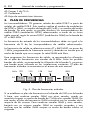
MHz 122
130
138
146
858
BW
7.9
2.0
4.3
7.9
7.0
8 MHz
8 MHz
8 MHz
Fig. 5 - Plan de frecuencias estándar
Si se establece un plan de frecuencias en la banda de VHF o en la banda
S baja, que combine canales QAM con otros canales, puede ser
necesario asignar un ancho de banda de 7 MHz a los canales QAM. De
este modo, el plan de frecuencias QAM coincidirá con los canales de la
mayoría de las normas. Para combinar canales QAM y otros canales,
bastará con no asignar canales QAM en canales ocupados y con
verificar que las señales QAM ocupen un ancho de banda inferior al
asignado.
Serie 912 - TQ
ESP - 9
MHz 122
130
136
140
146
154
161
BW
7.9
2.0 4.3
7.0
6.4
6.4
7.0
8 MHz
6 MHz
4 MHz
6 MHz
8 MHz
7 MHz
Fig. 6 - Plan de frecuencias ajustado
4.
CÁLCULO DE LA TASA DE SÍMBOLOS (SYMBOL
RATE S/R)
Para programar los receptores digitales QAM puede ser necesario
indicar al receptor cuál es la tasa de símbolos (symbol rate o S/R) de las
señales QAM. No se debe confundir esta tasa de símbolos con la de la
señal QPSK (se indica en los listados de canales de las revistas). También
es necesario conocer la tasa de símbolos de la señal QAM para calcular
el ancho de banda que ocupará la señal QAM.
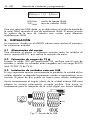
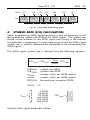
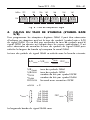
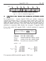
La tasa de símbolos de la señal QAM se calcula mediante la siguiente
fórmula:
S/RQAM = S/RQPSK .
S/RQAM
S/RQPSK
nQPSK
nQAM
FECQPSK
nQPSK
nQAM =
2
4
5
6
7
8
nQPSK
nQAM
. FEC
QPSK
tasa de símbolos QAM
tasa de símbolos QPSK
número de bits por símbolo QPSK
número de bits por símbolo QAM
forward error correction QPSK
=2
4
16
32
64
128
256
QAM
QAM
QAM
QAM
QAM
QAM
1/2
2/3
FECQPSK = 3/4
5/6
7/8
Y el ancho de banda de la señal QAM será:
10 - ESP
Manual de instalación y programación
BWQAM = 1,15 . S/RQAM
BWQAM
S/RQAM
ancho de banda QAM
tasa de símbolos QAM
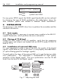
Para una señal de QPSK dada, es posible reducir el ancho de banda de
la señal QAM variando el tipo de modulación QAM. El anexo muestra
los valores de la tasa de símbolos más usuales para diferentes
modulaciones QAM.
5.
INSTALACIÓN
Los esquemas situados en el ANEXO indican como realizar el montaje y
las conexiones estándar.
5.1 Alimentación del equipo
Para alimentar el equipo es necesario conectar todos los módulos al
marco soporte MS-011, que realiza la conexión de masa.
5.2 Colocación de cargas de 75 Ω
Excepto la salida TEST del amplificador PA, verifique que el resto de
entradas y salidas no utilizadas están cargadas con una carga RS-275
(cód. 9120011) de 75 Ω.
5.3 Instalación de unidades externas LNB
Es muy importante apuntar correctamente la parábola, la calidad de las
señales digitales se degrada fuertemente cuando el apuntamiento no es
correcto (a pesar de que pueda ser bueno para señales analógicas)
Ajuste correctamente el ángulo (skew) de la unidad externa LNB para
obtener la mínima polarización cruzada posible. Este ajuste es
fundamental para la recepción de la señal digital con buena calidad.
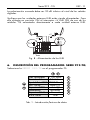
≥20dB
LNB
Fig. 7 - Ajuste de la LNB
Serie 912 - TQ
ESP - 11
La polarización cruzada debe ser 20 dB inferior al nivel de las señales
digitales.
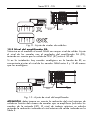
Verifique que las unidades externas LNB están siendo alimentadas. Para
ello coloque en posición ON el interruptor +V LNB (25) de uno de los
módulos TQ conectados directamente a cada unidad externa LNB.
+V
+V
+V.
LNB
ON
RF-275
75 Ω
SAT
OUT
OFF
Fig. 8 - Alimentación de las LNB
6.
DESCRIPCIÓN DEL PROGRAMADOR: SERIE 912-TQ
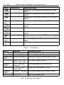
Seleccione la SERIE 912-TQ en el programador PS.
Frec. de entrada
1140 MHz
Frec. de salida
234 MHz
Symbol Rate QPSK 27500 Kbaud
FEC QPSK
Auto (-/-)
Espectro QPSK
Auto (-)
Modulación
64-QAM
Espectro QAM
Normal
B.E.R. QPSK
1E-6
Tab. 1 - Introducción/lectura de datos
T
T
T
T
T
T
T
12 - ESP
Manual de instalación y programación
FUNC. PANTALLA
GF Frec. de entrada
ENTRADA
1140 MHz
GF Frec. de salida
SALIDA
234 MHz
GF SymbolRate QPSK
SR
27500 Kbaud
GF FEC QPSK
FEC
Auto(-/-)
GF Espectro QPSK
EspecQPSK
Auto(-)
GF Modulacion
Mod.QAM
64-QAM
GF Espectro QAM
EspecQAM
Auto
HI B.E.R. QPSK
BER
2E-8 __!_____
F COPY Copiando...
COPY
F READ Leyendo...
READ
DESCRIPCIÓN
Selecciona la frecuencia de entrada de la señal
QPSK.
Selecciona la frecuencia de salida de la señal
QAM.
Selecciona la tasa de símbolos de la señal
QPSK.
Selecciona el FEC de la señal QPSK
Selecciona el tipo de espectro de la señal
QPSK.
Selecciona el modo de modulación QAM.
Selecciona el tipo de espectro de la señal
QAM.
Muestra el bit error rate (BER) de la señal
QPSK, después de ejecutar la función READ.
Transmite todos los datos de un transmodulador.
Lee todos los datos de un transmodulador.
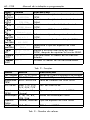
Tab. 2 - Funciones
DATO
Frec. entrada
Frec. salida
Symbol Rate
QPSK
FEC QPSK
VALOR
920..2150 MHz
47..862 MHz
8000..30000 Kb
Auto, 1/2, 2/3,
3/4, 5/6, 7/8
Espectro
Auto, Invertido,
QPSK
Normal
Modulación 4, 16, 32, 64,
128, 256
Espectro
Normal, Invertido
QAM
B.E.R. QPSK 1E-9..9E-1
DESCRIPCIÓN
Banda de FI para la frecuencia de entrada
Banda de RF para la frecuencia de salida
Tasa de símbolos de la señal QPSK
FEC de la señal QPSK
Tipo de espectro de la señal QPSK
Modo de modulación QAM
Tipo de espectro de la señal QAM
BER de la señal QPSK
Tab. 3 - Rango de valores
Serie 912 - TQ
ESP - 13
PANTALLA
Dato erroneo
DESCRIPCIÓN
El dato seleccionado no pertenece al rango de
valores indicado en la tabla 3.
Errordelectura Se ha producido un error durante la función
READ.
Tab. 4 - Avisos
Se recomienda programar las frecuencias de salida más bajas en los
módulos más alejados del amplificador y sucesivamente programar
frecuencias de salida más altas. De este modo se consigue la mejor
respuesta amplitud-frecuencia.
7.
ENVÍO DE DATOS AL TRANSMODULADOR TQ
7.1 Modo de programación
Para programar un transmodulador debe colocar en ON el conmutador
de programación (11), a partir de ese momento se iluminará el indicador
de programación. Mientras el indicador de programación permanece
iluminado, el transmodulador está preparado para recibir datos del
programador PS.
Una vez programado el transmodulador se debe desactivar el modo de
programación colocando el conmutador en OFF. El indicador de
programación se apagará.
7.2 Transmisión de datos
Seleccione la función deseada en la pantalla del programador PS y
ajuste el valor correcto de dicha función.
Para transmitir el dato, pulse la tecla T. El indicador de programación
parpadeará para indicar que el transmodulador ha recibido el dato.
8.
COPIA DE DATOS
Para evitar transmitir de uno en uno todos los datos del módulo TQ, se
puede utilizar la función COPY. Apuntando al receptor, pulse las teclas F
y COPY. Se debe mantener el programador PS apuntando al
transmodulador hasta que el mensaje Copiando... desaparece de la
pantalla. Durante la transmisión, el indicador de programación
permanece intermitente.
9.
LECTURA DE DATOS
Apuntando al TQ, pulse las teclas F y READ, aparecerá Leyendo...
en pantalla. Se leen todos los datos programados en el transmodulador.
14 - ESP
Manual de instalación y programación
Durante la lectura el indicador de programación permanece intermitente,
y durante este tiempo el transmodulador no debe recibir transmisiones.
Se debe mantener el programador PS apuntando al receptor hasta que
el mensaje Leyendo... desaparece de la pantalla.
Para consultar los datos recibidos, seleccione la función correspondiente
y visualizará los datos en la pantalla del programador.
10. AJUSTE DE NIVELES
10.1 Verificación de los módulos TQ
Compruebe que el indicador de enganche del transpondedor de satélite
QPSK (15), el indicador de transmodulación QPSK/QAM correcta (16)
y el indicador de canal de salida QAM correcto (18) de los
transmoduladores estén activados.
10.2 Niveles de los módulos TQ
Conecte un medidor de campo que cubra la banda de 47 a 862 MHz,
en el conector TEST (37) del amplificador PA. Compruebe que la salida
(38) del amplificador está cargada mediante el cable de distribución o
una carga RS-275 (cód. 9120011) de 75 Ω, y que la entrada de señal
(20) del primer módulo está cargada mediante una carga RS-275 (cód.
9120011) de 75 Ω.
Compruebe que los reguladores de nivel de salida (19) de cada módulo
TQ están a -0 dB. A continuación, ajuste los niveles de salida de cada
módulo TQ mediante el regulador de nivel de salida (19), de modo que
los niveles de los canales QAM estén aproximadamente dentro de un
margen de 2 dB.
Se recomienda programar las frecuencias de salida más bajas en los
módulos más alejados del amplificador y sucesivamente programar
frecuencias de salida más altas. De este modo se consigue la mejor
respuesta amplitud-frecuencia.
Serie 912 - TQ
TEST
ESP - 15
OUT
Fig. 9 - Ajuste de niveles de módulos
10.3 Nivel del amplificador PA
Sintonice en el medidor el canal QAM con mayor nivel de salida. Ajuste
el nivel de los canales con el regulador del amplificador PA (32),
teniendo en cuenta que la salida de TEST (37) está a -30 dB.
QAM
QAM
QAM
QAM
QAM
Si en la instalación hay canales analógicos en la banda de RF, es
conveniente ajustar el nivel de los canales QAM entre 5 y 15 dB menos
que los analógicos.
TEST
EXT
Fig. 10 - Ajuste de nivel del amplificador
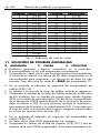
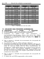
ATENCIÓN, debe tenerse en cuenta la reducción del nivel máximo de
salida en función del número de canales que se amplifican (incluidos los
canales de la entrada EXT). El nivel de trabajo máximo se calcula
restando la reducción indicada al nivel máximo de salida indicado en la
Tabla 5.
16 - ESP
Manual de instalación y programación
CANALES
2
3
4
5
6
7
8
9
10
11
12
13
14
15
16
17
REDUCCIÓN
0,0 dB
2,5 dB
3,5 dB
4,5 dB
5,0 dB
6,0 dB
6,5 dB
7,0 dB
7,0 dB
7,5 dB
8,0 dB
8,0 dB
8,5 dB
8,5 dB
9,0 dB
9,0 dB
CANALES
18
19
20
21
22
23
24
25
26
27
28
29
30
31
32
REDUCCIÓN
9,0 dB
9,5 dB
9,5 dB
10,0 dB
10,0 dB
10,0 dB
10,0 dB
10,5 dB
10,5 dB
10,5 dB
10,5 dB
11,0 dB
11,0 dB
11,0 dB
11,0 dB
Tab. 5 - Reducción del nivel de salida
11. SOLUCIÓN DE POSIBLES ANOMALÍAS
A.
A.
C.
S.
ANOMALÍA
C. CAUSA
S. SOLUCIÓN
Problemas generales y algunos indicadores no se encienden.
El transmodulador no ha sido programado correctamente.
Compruebe los datos con los que ha programado el transmodulador.
A continuación efectúe una lectura de los datos programados en el
transmodulador para comprobar si la transmisión de datos ha sido
correcta. Para ello pulse las teclas F y READ del programador PS.
A. No se enciende el indicador de enganche del transpondedor de
satélite QPSK (15).
C. La calidad o el nivel de la señal de satélite recibida es deficiente.
S. Compruebe la calidad de la señal de satélite midiendo el BER (tasa
de bits erróneos) con un medidor de campo para señales digitales
QPSK en la salida de señal de satélite (24) del último transmodulador
de la desmezcla. El BER medido después de la corrección de errores
debe ser inferior a 1E-8. En caso contrario, verifique la instalación y
apuntamiento de la antena y la unidad externa LNB. Compruebe que
el nivel de señal se encuentra dentro de los márgenes especificados
en la hoja de características técnicas (29).
A. No se enciende el indicador de enganche del tranpondedor de
satélite QPSK (15).
C. Los datos de la señal QPSK programados son erróneos.
S. Compruebe los valores de la tasa de símbolos (S/R), FEC y tipo de
espectro de la señal QPSK programados. Estos datos aparecen en los
Serie 912 - TQ
ESP - 17
listados de programas de los satélites, y el tipo de espectro puede
programarse de modo automático seleccionando Auto.
A. No se enciende el indicador de transmodulación QPSK/QAM
correcta (16).
C. La etapa de transmodulación QPSK/QAM no recibe señal QPSK.
S. Compruebe el indicador de enganche del transpondedor de satélite,
que debe estar encendido.
A. El indicador de transmodulación QPSK/QAM correcta (16) está
intermitente.
C. La etapa de transmodulación QPSK/QAM no puede generar la señal
QAM, por que la señal QAM tiene una tasa de símbolos mayor que
8.000 Kbaudios (equivalente a un ancho de banda mayor que 9,2
MHz).
S. Seleccione un tipo de modulación QAM que genere una señal QAM
con una tasa de símbolos menor (aumente el tipo de modulación
QAM).
A. No se enciende el indicador de canal de salida QAM (18).
C. El conversor de FI a canal no trabaja correctamente.
S. Verifique las tensiones de alimentación del transmodulador.
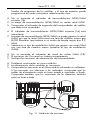
A. Problemas continuados en varios módulos.
C. La alimentación de los módulos es incorrecta.
S. Compruebe las tensiones en el último módulo utilizando un voltímetro.
Si las tensiones son inferiores a las indicadas, compruebe que los
cables de alimentación estén en buen estado e insertados a fondo.
Compruebe también, que los conectores de los diferentes módulos
estén en buen estado.
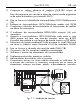
912
912
TQ-501
OUTPUT
5v
5v
13 v
13 v
30 v
5v
FA-203
Fig. 11 - Medición de tensiones
VDC
18 - ESP
Manual de instalación y programación
Index
ENG - 19
INDEX
SERIES 912-TQ
1 SAFETY INSTRUCTIONS...........................................................21
2 DESCRIPTION .........................................................................22
3 FREQUENCY PLAN..................................................................24
4 SYMBOL RATE (S/R) CALCULATION..........................................25
5 INSTALLATION ........................................................................26
6 DESCRIPTION OF THE PROGRAMMER: SERIES 912 - TQ............27
7 SENDING DATA TO THE TQ TRANSMODULATOR......................29
8 DATA COPYING......................................................................29
9 DATA READING ......................................................................29
10 ADJUSTMENT OF LEVELS .........................................................30
11 SOLUTIONS TO POSSIBLE ANOMALIES....................................32
ANNEX
1 INSTALLATION OF SERIES 912 - TQ........................................101
2 STANDARD FREQUENCY PLAN ..............................................105
3 SYMBOL RATE (S/R) ..............................................................106
20 - ENG
Installation and programming manual
Serie 912 - TQ
ENG - 21
SERIES 912 - TQ
1.
SAFETY INSTRUCTIONS
Make all IF, RF and supply connections before connecting the units to the
electric mains.
To meet the safety norms, the electrical installation must be protected by
a differential circuit-breaker. To connect the supply to the mains, use a
connecting strip. The green and yellow cable of the supply must be
grounded to the mains.
230 V
GREEN/YELLOW
Fig. 1 - Connection of ground cable of the power supply
Do not remove the unit covers while
connected to the mains. All repairs must
be performed by authorised technical
service staff. Internal manipulation of the
units cancels all warranties.
Fig. 2 - Do not manipulate while
connected
230 V
Make sure that the unit is properly ventilated. For
installation in a chest, use a CV-001 chest with built-in fan
+ 45 °C (Cod. 9120068) or a CP-710 chest (Cod. 9050041)
together with the VE-500 ventilator (Cod. 9050043). A
-- 10 °C unit working outside its temperature range (-10 to +45°C)
can be damaged beyond repair. Do not block or cover
the supply or cabinet ventilation slots.
Fig. 3 - Range of temperatures
22 - ENG
Installation and programming manual
Consult your supplier if you have any doubts concerning the installation,
operation or safety requirements of the units.
2.
DESCRIPTION
6
10
1
11
2
ON
OFF
ON
3
OVL.
ERROR
PROGRAM MODE
4
12
13
READ
IN
OK
14
INPUT
230 V~ ±20%
50/60Hz
QPSK/QAM
OK
912
5
OUTPUT
FA-203
TQ-501
OUT
OK
8
OUTPUT
I
5
V
2.2 A
5
V
2.2 A
13 V
1.3 A
13
V
1.3
A
30
V
0.35
A
18
19
- 15dB
29
30
PA-102
ON
- 10dB
- 0dB
- 0dB
42
6
912
17
5v
5v
13
13
30 v
V
15
16
912
31
32
20
33
21
34
22
35
7
SAT
IN
9
+13V
350mA max
23
SAT
OUT
26
24
LNB
27
EXT
ON
36
OFF
25
28
39
Fig. 4 - Series 912 - TQ
2.1 Description of the FA power supply
1- Mass connection
TEST
-30dB
OUT
37
38
40
41
Serie 912 - TQ
23456789-
ENG - 23
Indicator of correct operation
Overload indicator
Short-circuit or input undervoltage indicator
Supply output connector
Ventilation grooves
Connection cable to the mains
List of technical characteristics
Supply cable (120 mm)
2.2 Description of TQ transmodulators
10- Infrared receiver
11- Program mode switch
12- Programming indicator
13- Boxes for recording the input and output frequencies of the
transmodulator
14- Infrared emitter
15- QPSK satellite transponder hook-up Indicator
16- Correct QPSK/QAM transmodulation Indicador
17- Supply connectors
18- Correct QAM output channel Indicador
19- Level regulator of the output signal
20- F-connector for QAM signal input from upstream transmodulator
21- F-connector for QAM signal output to downstream transmodulator or
amplifier
22- Mass connection
23- F-connector for satellite signal input from upstream transmodulator or
from an external LNB unit
24- F-connector for satellite signal output to downstream transmodulator
25- Output voltage switch for the external LNB unit
26- Long connection bridge (45.2mm)
27- Short connection bridge (41.5mm)
28- Supply cable (50mm)
29- List of technical characteristics
2.3 Description of the PA amplifier
30- Supply connectors
31- Operating indicator
32- Level regulator of the output signal
33- F-connector for input #1 from the transmodulators
34- F-connector for input #2 from the transmodulators
35- Mass connection
36- F-connector for the extension signal input
37- F-connector for output signal testing at -30 dB
38- Signal output F connector
39- Supply cable (50 mm)
40- 75Ω F loads
24 - ENG
Installation and programming manual
41- F-connectors
42- List of technical characteristics
3.
FREQUENCY PLAN
TQ transmodulators generate DVB-C cable signals from DVB-S satellite
signals. Such transformation implies a change in modulation from QPSK
to QAM, a band change from IF to RF and a change in bandwidth. This
makes it possible to distribute the selected DVB-S satellite transponders
(QPSK modulation) through one single coaxial cable, according to the
DVB-C standard (QAM modulation) in the 47 to 862MHz band.
The input frequency of the transmodulators must be equal to the IF of the
selected satellite transponders.
The output frequency must be set to any value between 47 and 862 MHZ,
in 1MHz increments, by programming the centre frequency and ensuring
that the bandwidth to be occupied by the QAM signal is free.
In order to program the output frequencies, it is recommended to use a
frequency plan with 8MHz channels. Among the possible output bands,
the S band should preferably be used, since it is rarely used in existing
installations. The standard frequency plan is attached as an Appendix to
this Manual.
MHz 122
130
138
146
858
BW
7.9
2.0
4.3
7.9
7.0
8 MHz
8 MHz
8 MHz
Fig. 5 - Standard frequency plan
In the event of setting up a frequency plan in the VHF band or in the low
S band, which would combine QAM channels with other channels, it
might be necessary to allocate a 7MHz bandwidth to the QAM channels.
As a result, the QAM frequency plan will coincide with the channels of
most standards. In order to combine QAM channels with other channels,
it will be enough to refrain from allocating QAM channels to already
occupied channels and to check that the QAM signals occupy a
bandwidth inferior to the assigned one.
Serie 912 - TQ
ENG - 25
MHz 122
130
136
140
146
154
161
BW
7.9
2.0 4.3
7.0
6.4
6.4
7.0
8 MHz
6 MHz
4 MHz
6 MHz
8 MHz
7 MHz
Fig. 6 - Adjusted frequency plan
4.
SYMBOL RATE (S/R) CALCULATION
When programming QAM digital receivers, it may be necessary to tell
the receiver the symbol rate (S/R) of the QAM signals. This symbol rate
should not be mistaken for the QPSK signal rate (shown in the channel
lists published in magazines). It is also necessary to know the QAM signal
symbol rate in order to determine the bandwidth to be occupied by the
QAM signal.
The QAM signal symbol rate is derived from the following equation:
S/RQAM = S/RQPSK .
S/RQAM
S/RQPSK
nQPSK
nQAM
FECQPSK
nQPSK
nQAM =
2
4
5
6
7
8
nQPSK
nQAM
. FEC
QPSK
symbol rate QAM
tsymbol rate QPSK
number of bits per QPSK symbol
number of bits per QAM symbol
forward error correction QPSK
=2
4
16
32
64
128
256
QAM
QAM
QAM
QAM
QAM
QAM
And the QAM signal bandwidth will be:
1/2
2/3
FECQPSK = 3/4
5/6
7/8
26 - ENG
Installation and programming manual
BWQAM = 1,15 . S/RQAM
BWQAM
S/RQAM
bandwidth QAM
symbol rate QAM
For any given QPSK signal, the QAM signal bandwidth can be reduced
by changing the type of QAM modulation. The table below shows the
most common symbol rate related to different QAM modulations.
5.
INSTALLATION
The drawings in the ANNEX show how to perform the assembly and the
standard connections.
5.1 Unit supply
To supply the unit, it is necessary to connect every module to the MS-011
support framework, which performs the mass connection.
5.2 Placing of 75 Ω load
Except the TEST output of the PA amplifier, verify that the remaining
unused inputs and outputs are loaded with an RS-275 (code 9120011)
load of 75 Ω.
5.3 Installation of external LNB units
It is very important to make a note of the dish, the quality of the digital
signals, which fade out very much when it is not properly recorded down
(in spite of being good for analogic signals).
Correctly adjust the skew of the external LNB unit to get the best possible
cross polarisation. This adjustment is fundamental for high quality
reception of the digital signal. The cross polarisation must be 20 dB
lower than the level of the digital signals.
≥20dB
LNB
Fig. 7 - Adjusting the LNB
Serie 912 - TQ
ENG - 27
Verify that the external LNB units are supplied. To do so, turn the +V LNB
(25) switch on in one of the TQ modules that are directly connected to
each LNB unit.
+V
+V
+V.
LNB
RF-275
75 Ω
SAT
OUT
ON
OFF
Fig. 8 - Supplying the LNB
6.
DESCRIPTION OF THE PROGRAMMER: SERIES 912TQ
Select SERIE 912-TQ in the PS programmer.
Input frequency
1140 MHz
Output frequency
234 MHz
Symbol Rate QPSK 27500 Kbaud
FEC QPSK
Auto
QPSK Spectrum
Auto
Modulation
64-QAM
QAM Spectrum
Normal
B.E.R. QPSK
1E-6
Tab. 1 - Data
T
T
T
T
T
T
T
28 - ENG
Installation and programming manual
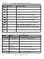
FUNC. SCREEN
DESCRIPTION
GF Input frequncy Select the QPSK signal input frequency.
INPUT
1140 MHz
GF Output frequency Select the QAM output signal frequency.
OUTPUT
234 MHz
GF SymbolRate QPSK Select the symbol rate of the QPSK signal.
SR
27500 Kbaud
GF FEC QPSK
Select the FEC of the QPSK signal.
FEC
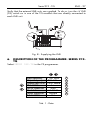
Auto(-/-)
GF QPSK Spectrum Select the type of QPSK signal spectrum.
SpecQPSK
Auto(-)
GF Modulation
Select the QAM modulation mode.
Mod.QAM
64-QAM
GF QAM Spectrum Select the type of QAM signal spectrum.
SpecQAM
Auto
HI B.E.R. QPSK Shows the bit error rate (BER) of a QPSK
BER
2E-8 __!_____ signal, after the function READ has been executed.
F COPY Copy...
Transmit all the data from a transmodulator.
COPY
F READ Read...
Read all the data of a transmodulator..
READ
Tab. 2 - Functions
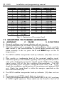
DATA
Input frequen.
Output freq.
Symbol Rate
QPSK
FEC QPSK
VALUE
920..2150 MHz
47..862 MHz
8000..30000 Kb
Auto, 1/2, 2/3,
3/4, 5/6, 7/8
QPSK
Auto, Inverted,
Spectrum
Normal
Modulation 4, 16, 32, 64,
128, 256
QAM
Normal, Inverted
Spectrum
B.E.R. QPSK 1E-9..9E-1
DESCRIPTION
IF band for input frequency.
RF band for output frequency.
Symbol rate of QPSK signal.
FEC of QPSK signal.
Type of QPSK signal spectrum.
QAM modulation mode.
Type of QAM signal spectrum.
BER of QPSK signal.
Tab. 3 - Range of values
Serie 912 - TQ
ENG - 29
SCREEN
Data error
DESCRIPTION
The data selected does not belong to the range of
values indicated in table 3.
Reading error An error occurred during the READ function.
Tab. 4 - Warnings
We recommend programming the lowest output frequencies in the
modules furthest from the amplifier, and successively programming higher
output frequencies. This achieves the best width-frequency response for
the module.
7.
SENDING DATA TO THE TQ TRANSMODULATOR
7.1 Programming Mode
For a transmodulator to be programmed, the 'Program' switch (11) must
be switched ON; as this is done, the 'Programming' indicator turns on.
While the indicator is lit, the transmodulator is ready to receive data from
the PS programmer.
Once the transmodulator has been programmed, the Programming Mode
has to be disabled by switching OFF the 'Program' switch. The
'Programming' indicator turns off.
7.2 DATA TRANSMISSION
Select the desired function on the PS programmer screen and adjust the
right value of that function.
To transmit, press the T key. The programming led will blink to indicate
that the transmodulator has received the datum.
8.
DATA COPYING
The COPY function is provided, to avoid transmitting the TQ module data
one by one. Aiming at the transmodulator, press the F and COPY keys.
The PS programmer must be kept aimed at the transmodulator until the
Copy... message is deleted from the screen. The programming led will
blink while transmitting.
9.
READING THE DATA
Aiming the transmodulator, press the F and READ keys, and Read...
will be displayed on the screen. All the data programmed in the
transmodulator will be read.
30 - ENG
Installation and programming manual
While reading, the program led of the transmodulator will blink; the
transmodulator must not receive other transmissions at the same time.
Keep the PS programmer aimed at the transmodulator until the Read...
message is deleted from the screen.
To consult the data received, select the corresponding function, which will
display the datum on the screen of the programmer.
10. ADJUSTMENT OF LEVELS
10.1 Verifying the TQ modules
Check that the QPSK satellite transponder hook-up indicator (15), the
'correct QPSK/QAM transmodulation' indicator (16) and the 'correct
QAM output channel' indicator (18) on the transmodulators are activated.
10.2 Levels of the TQ modules
Connect a signal level meter that covers the band from 47 to 862 MHz
in the TEST connector (37) of the PA amplifier. Make sure that the output
(38) of the amplifier is charged with the distribution cable or an RS-275
(code 9120011) charge of 75 Ω, and that the signal inlet (20) of the first
module is charged with an RS-275 (code 9120011) charge of 75 Ω.
Verify that the output level regulators (19) of each TQ module are at -0
dB. Next, adjust the output levels of each TQ module, using the output
level regulator (19), so that the QAM channel levels are roughly within a
margin of 2 dB.
TEST
OUT
Fig. 9 - Adjusting the levels of the modules
Serie 912 - TQ
ENG - 31
We recommend programming the lowest output frequencies in the
modules furthest from the amplifier, and successively programme higher
output frequencies. This achieves the best width-frequency response for
the module.
10.3 Level of the PA amplifier
On the meter, tune the QAM channel with the highest output level. Adjust
the level of the channels, using the PA amplifier regulator (32), bearing in
mind that the TEST output (37) must be -30 dB.
QAM
QAM
QAM
QAM
QAM
If the installation features analogue channels in the RF band, the QAM
channel level should be set 5 to 15 dB less than the analogue channel
level.
TEST
EXT
Fig. 10 - Adjusting the amplifier level
WARNING: It is essential that the maximum output level reduction in
relation to the number of channels being amplified (including the EXT
input channels) should be taken into account. The maximum work level is
calculated by subtracting the reduction indicated from the maximum
output level indicated in the Table 5.
32 - ENG
Installation and programming manual
CHANNELS REDUCTION
2
0,0 dB
3
2,5 dB
4
3,5 dB
5
4,5 dB
6
5,0 dB
7
6,0 dB
8
6,5 dB
9
7,0 dB
10
7,0 dB
11
7,5 dB
12
8,0 dB
13
8,0 dB
14
8,5 dB
15
8,5 dB
16
9,0 dB
17
9,0 dB
CHANNELS
18
19
20
21
22
23
24
25
26
27
28
29
30
31
32
REDUCTION
9,0 dB
9,5 dB
9,5 dB
10,0 dB
10,0 dB
10,0 dB
10,0 dB
10,5 dB
10,5 dB
10,5 dB
10,5 dB
11,0 dB
11,0 dB
11,0 dB
11,0 dB
Tab. 5 - Reduction of the output level
11. SOLUTIONS TO POSSIBLE ANOMALIES
A.
A.
C.
S.
ANOMALY
C. CAUSE
S. SOLUTION
General problems and some indicators do not turn on.
The transmodulator has not been correctly programmed.
Check the data used to program the transmodulator. Next, read the
data stored in the transmodulator to ensure data transmission took
place correctly. To do so, press the F and READ keys on the PS
programmer.
A. The QPSK satellite transponder hook-up indicator (15) does not turn
on.
C. Poor quality or inadequate level of the received satellite signal.
S. Check the quality of the satellite signal by measuring the BER (bit error
rate) with a field measurement for digital signals QPSK at the satellite
signal output (24) of the last unmixing transmodulator. The BER
measured after error correction should be lower than 1E-8. If not,
check the installation and direction of the antenna and external LNB
unit. Check the signal level is within the margins specified on the
technical datasheet (29).
A. The QPSK satellite transponder hook-up indicator (15) does not turn
on.
C. The programmed QPSK signal data are incorrect.
S. Check the programmed values of the symbol rate (S/R), FEC and type
of QPSK signal spectrum. These data can be found in the lists of
Serie 912 - TQ
ENG - 33
satellite programs and the type of spectrum can be programmed
automatically by selecting "Auto".
A. The 'correct QPSK/QAM transmodulation' indicator (16) does not
turn on.
C. The QPSK/QAM transmodulation stage does not receive any QPSK
signal.
S. Make sure the satellite transponder hook-up indicator is on.
A. The 'correct QPSK/QAM transmodulation' indicator (16) is flashing.
C. The QPSK/QAM transmodulation stage cannot generate the QAM
signal, because the symbol rate of the QAM signal is greater than
8.000 Kbauds (equivalent to a bandwidth greater than 9,2 MHz).
S. Select a QAM modulation mode capable of generating a QAM signal
of a lower symbol rate (increase the QAM modulation mode).
A. The QAM output channel indicator (18) does not turn on.
C. The IF-to-channel converter does not work properly.
S. Check the transmodulator supply voltages.
A. Continuous problems in several modules.
C. Wrong module supply
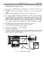
S. Check the voltages in the last module using a voltmeter. If the voltages
are lower than the indicated ones, check that the supply cables are in
good shape and deeply plugged in.
912
912
TQ-501
OUTPUT
5v
5v
13 v
13 v
30 v
5v
FA-203
Fig. 11 - Measuring voltage
VDC
34 - ENG
Installation and programming manual
Sommaire
FRA - 35
SOMMAIRE
SERIE 912 - TQ
1 INSTRUCTIONS DE SÉCURITÉ ..................................................37
2 DESCRIPTIF TECHNIQUE DES PRODUITS ...................................38
3 PLAN DE FREQUENCES ...........................................................40
4 CALCUL DU TAUX DE SYMBOL (SYMBOL RATE S/R)...................41
5 INSTALLATION ........................................................................42
6 DESCRIPTION DU PROGRAMMATEUR: SERIE 912 - TQ ..............43
7 TRANSMISSION DES PARAMETRES AU TRANSMODULATION
TQ .........................................................................................45
8 COPIE DES PARAMETRES .........................................................45
9 LECTURE DES PARAMETRES......................................................45
10 REGLAGE DES NIVEAUX..........................................................46
11 SOLUTIONS DES ANOMALIES POSSIBLES.................................48
ANNEXE
1 INSTALLATION SERIE 912 - TQ ...............................................101
2 PLAN DE FRÉQUENCES STANDARD .......................................105
3 TAUX DE SYMBOLS (S/R).......................................................106
36 - FRA
Manuel d’installation et programmation
Serie 912 - TQ
FRA - 37
SERIE 912 - TQ
1.
INSTRUCTIONS DE SÉCURITÉ
Ne pas relier les connexions de HF et les cables d'alimentation entre les
différents modules si l'alimentation est branchée au secteur.
Pour respecter les normes de sécurité, l'installation électrique doit être
protégée par un disjoncteur différentiel. Pour relier l'alimentation FA au
réseau électrique, utilisez une borne de connexion ou une fiche.
Raccorder le cable vert-jaune de l'alimentation à la prise de terre de
l'installation.
230 V
VERT / JAUNE
Fig. 1 - Connexion à la terre de l'alimentation FA
Pour relier l'alimentation au réseau
électrique, utilisez une borne de
connexion ou une fiche.
Ne pas ôter les connecteurs des modules
pendant que l'équipement est connecté
au réseau électrique. Toute intervention
ou réparation doit être réalisée par le
personnel du service technique autorisé.
Une intervention non conforme annulera
automatiquement
la
garantie
du
fabricant.
Fig. 2 - Ne pas manipuler sous tension
230 V
Veuillez vérifier que l'équipement est correctement ventilé.
Dans le cas d'installation en coffret. Utiliser le coffret avec
ventilateur CV-001 (cod. 9120068) ou le coffret CP-710
+ 45 °C (cod. 9050041), avec le ventilateur VE-500
(cod.9050043). Un équipement qui fonctionnerait hors
-- 10 °C de la plage de température recommandée (-10 à +45°C)
peut rester irrémédiablement endommagé. Ne bloquez
pas ou ne couvrez pas les rainures d'aération de
l'alimentation, ni du coffret.
Fig. 3 - Plage de températures
38 - FRA
Manuel d’installation et programmation
Consultez votre fournisseur si vous avez un doute quelconque quant à
l'installation, au fonctionnement ou aux conditions de sécurité de
l'équipement.
2.
DESCRIPTION
6
10
1
11
2
ON
OFF
ON
3
OVL.
ERROR
PROGRAM MODE
4
12
13
READ
IN
OK
14
INPUT
230 V~ ±20%
50/60Hz
QPSK/QAM
OK
912
5
OUTPUT
FA-203
TQ-501
OUT
OK
8
OUTPUT
I
5
V
2.2 A
5
V
2.2 A
13 V
1.3 A
13
V
1.3
A
30
V
0.35
A
18
19
- 15dB
29
30
PA-102
ON
- 10dB
- 0dB
- 0dB
42
6
912
17
5v
5v
13
13
30 v
V
15
16
912
31
32
20
33
21
34
22
35
7
SAT
IN
9
+13V
350mA max
23
SAT
OUT
26
24
LNB
EXT
ON
36
OFF
TEST
27
25
28
39
Fig. 4 - Serie 912 - TQ
2.1 Description de l'alimentation FA
1- Connection de masse
-30dB
OUT
37
38
40
41
Serie 912 - TQ
23456789-
FRA - 39
Voyant de fonctionnement correct
Voyant de surcharge
Voyant de court-circuit ou de subtension d'entrée
Connecteur de sortie de l'alimentation
Rainures de ventilation
Cable de branchement au secteur électrique
Manuel technique et d'instructions
Cable d'alimentation (120 mm)
2.2 Description des transmodulateurs TQ
10- Récepteur d'infrarouges
11- Interrupteur pour la programmation (PROGRAM MODE)
12- Voyant de programmation
13- Cases pour noter les fréquences d'entrée et de sortie du
transmodulateurs
14- Emetteur d'infrarouges
15- Indicateur de vérouillage du transpondeur satellite en QPSK
16- Indicateur de transmodulation QPSK/QAM correcte
17- Connecteurs d'alimentation
18- Indicateur de sortie correcte du canal QAM
19- Régulateur du niveau du signaL de sortie
20- Connecteur F d'entrée du signal QAM du transmodulateur précédent
21- Connecteur F de sortie du signal QAM vers le transmodulateur suivant
ou l'amplificateur
22- Connexion de masse
23- Connecteur F d'entrée du signal QPSK du transmodulateur précédent
ou du LNB
24- Connecteur F de sortie du signal QPSK vers le transmodulateur suivant
25- Interrupteur de tension de sortie pour la source LNB externe
26- Pontet de connection supérieur (45,2 mm)
27- Pontet de connection inférieur (41,5 mm)
28- Cable d'alimentation (50 mm)
29- Manuel technique et d'instructions
2.3 Description de l'amplificateur PA
30- Connecteurs d'alimentation
31- Voyant de fonctionnement correct
32- Régulateur du niveau du signal de sortie
33- Connecteur F de l'entrée numéro 1 depuis les transmodulateurs
34- Connecteur F de l'entrée numéro 2 depuis les transmodulateurs
35- Connexion de masse
36- Connecteur F d'entrée du signal auxiliaire
37- Conecteur F du test a -30 dB du signal de sortie
38- Connecteur F dusignal de sortie
39- Cable d'alimentation (50 mm)
40- Charges F de 75 Ω
40 - FRA
Manuel d’installation et programmation
41- Connecteurs F
42- Manuel technique et d'instructions
3.
PLAN DE FREQUENCES
Les transmodulateurs TQ générent un signal pour réseaux câblés DVB-C à
partir du signal satellite DVB-S. ce changement implique le changement
de modulation de QPSK en QAM, un changement de bande FI à RF et un
changement de largeur de bande. A partir de ce mode il est possible de
distribuer les transpondeurs satellites DVB-S (modulation QPSK)
sélectionnés à travers un unique câble coaxial selon la norme DVB-C
(modulation QAM) dans la bande 47 à 862 MHz.
La fréquence d'entrée des transmodulateurs doit être égale à la fréquence
FI des transpondeurs sélectionnés du satellite.
La fréquence de sortie sera sélectionnée entre 47 et 862 MHz, par pas
de 1 MHz en programmant la fréquence centrale et en vérifiant que la
largeur de bande que va occuper le canal QAM est libre.
Pour programmer la fréquence de sortie, il est recommandé l'utilisation
d'un plan de fréquence avec des canaux de 8 MHz. Entre les divers
bandes disponibles il est recommandé d'utiliser la bande S, car c'est une
bande peu utilisée dans les installations existantes. Le plan de fréquence
standard se trouve en annexe de ce manuel.
MHz 122
130
138
146
858
BW
7.9
2.0
4.3
7.9
7.0
8 MHz
8 MHz
8 MHz
Fig. 5 - Plan de fréquences standard
Si on établit un plan de fréquence dans la bande VHF ou dans la bande
S basse, qui combine des signaux QAM avec d'autres canaux, il peut
être nécessaire d'utiliser une largeur de bande de 7 MHz pour les canaux
QAM. De cette façon le plan de fréquence QAM coïncidera avec les
canaux de la majorité des normes. Pour combiner des canaux QAM et
d'autres canaux, on vérifiera de ne pas assigner des canaux QAM sur
des canaux occupés et que le siganl QAM occupe une largeur de bande
inférieure à la place libre.
Serie 912 - TQ
FRA - 41
MHz 122
130
136
140
146
154
161
BW
7.9
2.0 4.3
7.0
6.4
6.4
7.0
8 MHz
6 MHz
4 MHz
6 MHz
8 MHz
7 MHz
Fig. 6 - Plan de fréquences réglé
4.
CALCUL DU TAUX DE SYMBOLS (SYMBOL RATE
S/R)
Pour programmer les récepteurs digitaux QAM il peut être nécessaire
d'indiquer au récepteur quel est le taux de symbols (symbol rate o S/R)
du signal QAM. On ne doit pas confondre ce taux de symbols avec le
signal QPSK (ce dernier est indiqué dans les revues spécialisées). Il est
aussi nécessaire de connaître le taux de symbols du signal QAM pour
calculer la largeur de bande qu'occupera le canal QAM.
La taux de symbols du signal QAM se calcule avec la formule suivante:
S/RQAM = S/RQPSK .
S/RQAM
S/RQPSK
nQPSK
nQAM
FECQPSK
nQPSK
nQAM =
2
4
5
6
7
8
nQPSK
nQAM
. FEC
QPSK
taux de symbols QAM
taux de symbols QPSK
nombre de bits par symbol QPSK
nombre de bits par symbol QAM
forward error correction QPSK
=2
4
16
32
64
128
256
QAM
QAM
QAM
QAM
QAM
QAM
La largeurde bande du signal QAM sera:
1/2
2/3
FECQPSK = 3/4
5/6
7/8
42 - FRA
Manuel d’installation et programmation
BWQAM = 1,15 . S/RQAM
BWQAM
S/RQAM
Largeur de bande QAM
taux de symbols QAM
Pour un signal QPSK donné, il est possible de réduire la largeur de bande
du signal QAM en faisant varier le type de modulation QAM. L'annexe
indique les valeurs des taux de symbols les plus usuels pour différentes
modulations QAM.
5.
INSTALLATION
Les schémas situés en ANNEXE montrent comment réaliser le montage et
les branchements standards.
5.1 Alimentation de l'équipement
Pour alimenter l'équipement il faut fixer tous les modules au cadre de
montage MS-011, qui effectue la liaison à la masse .
5.2 Positionnement des charges 75 Ω
Sauf pour la sortie de TEST de l'amplificateur PA, vérifiez que le reste des
entrées et sorties non utilisées soient chargées avec une charge RS-275
(code 9120011) de 75 Ω.
5.3 Installation des sources externes LNB
Il est très important de pointer très précisément la parabole, la qualité des
signaux numériques se dégrade fortement quand le pointage n'est pas
correct (bien que celà puisse convenir pour les signaux analogiques).
Ajustez correctement l'angle (skew) de la source externe LNB pour obtenir
une contre-polarisation (horizontal-vertical ) minimum possible, voire
nulle.
≥20dB
LNB
Fig. 7 - Pointage de la LNB
Serie 912 - TQ
FRA - 43
Ce réglage est fondamental pour une réception de bonne qualité des
signaux numériques. La contre-polarisation doit être inférieure de 20 dB
du niveau des signaux numériques.
Vérifiez que les sources externes LNB soient bien alimentées. Pour celà,
mettez en position ON l'interrupteur +V LNB (25) de l'un des modules TQ
connectés directement à chaque source externe LNB.
+V
+V
+V.
LNB
ON
RF-275
75 Ω
SAT
OUT
OFF
Fig. 8 - Alimentation de la LNB
6.
DESCRIPTION DU PROGRAMMATEUR: SERIE 912TQ
Sélectionnez la SERIE 912-TQ sur le programmateur PS.
Fréquence entrée
1140 MHz
Fréquence sortie
234 MHz
Symbol Rate QPSK 27500 Kbaud
FEC QPSK
Auto
Spectre QPSK
Auto
Modulation QAM 64QAM
Spectre QAM
Normal
BER QPSK
1E-6
Tab. 1 - Grille de programmation
T
T
T
T
T
T
T
44 - FRA
Manuel d’installation et programmation
FUNC. ECRAM
GF Frequence entree
ENTRÉE
1140 MHz
GF Frequence sortie
SORTIE
234 MHz
GF SymbolRate QPSK
SR
27500 Kbaud
GF FEC QPSK
FEC
Auto(-/-)
GF Spectre QPSK
SpecQPSK
Auto(-)
GF Modulation
Mod.QAM
64-QAM
GF Spectre QAM
SpecQAM
Auto
HI B.E.R. QPSK
BER
2E-8 __!_____
F COPY Copier...
COPY
F READ Lire...
READ
DESCRIPTION
Selectionne la fréquence d'entrée du signal.
QPSK.
Select the QAM output signal frequency.
Selectionne la fréquence de sortie du signal
QPSK.
Selectionne le FEC du signal QPSK.
Selectionne le type de spectre du signal
QPSK.
Selectionne le mode de modulation QAM.
Selectionne le type de spectre du signal
Montre le bit error rate (BER) du signal
QPSK, après l'exécution de la fonction READ.
Transmet toutes les données vers un
transmodulateur.
Lit toutes les données d'un transmodulateur.
Tab. 2 - Tableau des fonctions
PARAM.
Input frequen.
Output freq.
Symbol Rate
QPSK
FEC QPSK
VALEUR
920..2150 MHz
47..862 MHz
8000..30000 Kb
Auto, 1/2, 2/3,
3/4, 5/6, 7/8
SpecQPSK Auto, Inverti,
Normal
Modulation 4, 16, 32, 64,
128, 256
QAM
Normal, Inverti
Spectrum
B.E.R. QPSK 1E-9..9E-1
DESCRIPTION
Bande BIS pour la fréquence d'entrée
Bande RF pour la fréquence de sortie
Taux de symbols pour le signal QPSK
FEC du signal QPSK
Type de spectre du signal QSPSK
Type de spectre du signal QAM
Tipo de espectro de la señal QAM
BER du signal QPSK
Tab. 3 - Tableau des valeurs
Serie 912 - TQ
FRA - 45
ECRAN
DESCRIPTION
Donee erronee Le paramètre sélectionné n’appartient pas à la plage
des valeurs indiquées dans le tableau 3.
Erreur lecture Il s’est produit une erreur durant la fonction
READ.
Tab. 4 - Tableau des avertissements
L'on recommande de programmer les fréquences de sortie les plus basses
sur les modules les plus éloignés de l'amplificateur et ensuite programmer
les fréquences de sortie les plus hautes. De cette façon l'on obtient la
meilleure réponse amplitude-fréquence.
7.
ENVOI DE DONNEES AU TRANSMODULATEUR TQ
7.1 Mode de programmation
Pour programmer un transmodulateur il faut positionner sur ON le
commutateur de programmation (11), à partir de ce moment la LED de
programmation sera allumée. Le transmodulateur est près à recevoir des
données du programmateur PS.
Lorsque la programmation du transmodulateur est terminée il faut
positionner le commutateur de programmation (11) sur OFF, la led de
programmation s'éteindra.
7.2 Transmission des paramètres
Sélectionnez la fonction désirée sur l'écran du programmateur PS et
programmez la valeur correcte pour cette fonction.
Pour transmettre ce paramètre au TQ, appuyez sur la touche T du
programmateur. Le voyant de programmation clignote pour indiquer que
le TQ a bien reçu les paramètres.
8.
COPIE DES PARAMETRES
Pour éviter la transmission une à une de toutes les données du module TQ,
on peut utiliser la fonction COPY En visant et en maintenant le
programmateur PS vers le TQ, appuyez sur les touches F puis COPY: le
message Copier... apparaît sur l'écran. Pendant la transmission
l'indicateur de programmation sera clignotant.
9.
LECTURE DES PARAMÈTRES
En visant le récepteur, appuyez les touches F puis READ, il apparaitra
Lire... sur l'écran. Tous les paramètres programmés sur le récepteur
seront disponibles sur l'écran du programmateur.
46 - FRA
Manuel d’installation et programmation
Pendant la lecture l'indicateur de programmation du transmodulateur
clignotera et durant ce temps le récepteur ne doit pas recevoir d'autres
transmissions.
Le programmateur PS doit rester pointé vers le récepteur jusqu'à ce que
le message Lire... disparaisse de l'écran.
Pour consulter les paramètres reçus, sélectionnez la fonction désirée
correspondante et visualisez les données sur l'écran du programmateur.
10. REGLAGE DES NIVEAUX
10.1 Vérification des modules TQ
Vérifiez que l'indicateur de verrouillage du transpondeur satellite QPSK
(15), l'indicateur de transmodulation QPSK/QAM (16) et l'indicateur de
canal de sortie QAM (18) des transmodulateurs soient allumés.
10.2 Niveaux des modules TQ
Connectez un mesureur de champ que couvre la bande de 47 à 862
MHz, sur le connecteur de TEST (37) de l'amplificateur PA. Vérifiez que
la sortie (38) de l'amplificateur soit chargée au moyen du cable de
distribution ou bien d'une charge RS-275 (code 9120011) de 75 Ω, et
vérifiez que l'entrée du signal (20) du premier module est bien chargée
avec une charge RS-275 (code 9120011) de 75 Ω.
Vérifiez que les régulateurs de niveaux de sortie (19) de chaque module
TQ soient bien à -0 dB. Ensuite ajuster grace au réglage (19) les niveaux
de sortie de chaque module TQ de façon à ce que les niveaux de chaque
canal QAM se trouve dans une marge de 2 dB.
TEST
OUT
Fig. 9 - Réglage de niveaux des modules
Serie 912 - TQ
FRA - 47
Il est recommandé de programmer les fréquences de sortie les plus basses
sur les modules les plus éloignés de l'amplificateur et de programmer
ensuite les fréquences de sortie les plus hautes sur les modules les plus
prés de l'amplificateur. De cette façon l'on obtiendra la meilleure réponse
amplitude-fréquence.
10.3 Niveau de l'amplificateur PA
Synthonisé sur le mesureur de champ le millieu du canal QAM qui à le
plus grand niveau de sortie. Ajustez le niveau avec le réglage (32) qui se
trouve sur l'amplificateur PA, en tenant compte que la sortie test est à -30
dB.
QAM
QAM
QAM
QAM
QAM
Si l'installation comporte des canaux analogiques dans la bande RF, il est
recommandé de régler le niveau des canaux QAM entre 5 et 15 dB en
dessous des canaux analogiques
TEST
EXT
Fig. 10 - Réglage du niveau de l'amplificateur
ATTENTION vous devez prendre en compte la réduction du niveau
maximum de sortie en fonction du nombre de canaux amplifiés (en
incluant les canaux de l'entrée EXT). Le niveau de travail maximum se
calcule en enlevant la réduction indiquée au niveau maximum de sortie
indiqué sur le Table 5.
48 - FRA
Manuel d’installation et programmation
CANAUX
2
3
4
5
6
7
8
9
10
11
12
13
14
15
16
17
REDUCTION
0,0 dB
2,5 dB
3,5 dB
4,5 dB
5,0 dB
6,0 dB
6,5 dB
7,0 dB
7,0 dB
7,5 dB
8,0 dB
8,0 dB
8,5 dB
8,5 dB
9,0 dB
9,0 dB
CANAUX
18
19
20
21
22
23
24
25
26
27
28
29
30
31
32
REDUCTION
9,0 dB
9,5 dB
9,5 dB
10,0 dB
10,0 dB
10,0 dB
10,0 dB
10,5 dB
10,5 dB
10,5 dB
10,5 dB
11,0 dB
11,0 dB
11,0 dB
11,0 dB
Tab. 5 - Réduction du niveau de sortie
11. SOLUTIONS AUX POSSIBLES ANOMALÍES
A.
A.
C.
S.
ANOMALIE
C. CAUSE
S. SOLUTION
Problèmes généraux certaines LEDS ne s'allument pas.
Le transmodulateur n'est pas programmé correctement.
Vérifiez les données programmées dans le transmodulateur. Ensuite
éffectuez une lecture des données programmées dans le
transmodulateur et comparées les avec les données transmises pour
voir si la transmission a été correcte. Pour cela taper sur la touche F
puis READ du programmateur PS.
A. L'indicateur de vérrouillage du transpondeur satellite QPSK (15) ne
s'allume pas.
C. La qualité ou le niveau du signal satellite reçu est mauvaise.
S. Vérifiez la qualité du signal satellite en mesurant le BER (BIT ERROR
RATE) avec un mesureur de champ pour signaux numériques QPSK à
la sortie du signal satellite (24) du dernier transmodulateur découplé.
Le BER mesuré aprés la correction d'erreurs doit être inférieur à 1 E8. Dans le cas contraire, vérifiez que l'installation et le pointage de la
parabole et de la source LNB sont correctes. Vérifier que le niveau du
signal se trouve dans les marges spécifiées sur la feuille des
caractéristiques techniques (29).
A. L'indicateur de vérrouillage du transpondeur satellite QPSK (15) ne
s'allume pas.
C. Les données du signal QPSK programmées sont erronées.
Serie 912 - TQ
FRA - 49
S. Vérifiez les valeurs du taux de symbols (S/R), FEC et le type de
spectre du signal QPSK programmé. Ces données sont inscrites dans
les listings satellites des revues spécialisées, le type de spectre peut
être programmé en mode automatique.
A. L'indicateur de transmodulation correcte QPSK/QAM (16) ne
s'allume pas.
C. L'étage de transmodulation QPSK/QAM ne reçoit pas un signal
QPSK.
S. Vérifier si l'indicateur de verrouillage QPSK du transpondeur est
allumé.
A. L'indicateur de transmodulation correcte QPSK/QAM (16) clignote.
C. L'étage de transmodulation QPSK/QAM ne peut pas généré un signal
QAM, car le taux de symbols programmé est supérieur à 8.000
Kbaudios (équivalent à une largeur de bande supérieur à 9,2 MHz).
S. Sélectionnez un type de modulation QAM qui génére un signal QAM
avec un taux de symbols plus faible (augmentez le type de modulation
QAM).
A. L'indicateur de sortie QAM (18) ne s'allume pas.
C. Le transmodulateur FI / RF ne travaille pas correctement.
S. Vérifiez les tensions d'alimentation du transmodulateur.
A. Problèmes continuels avec divers modules.
C. L'alimentation des modules est incorrecte.
S. Vérifiez les tensions au dernier module au moyen d'un voltmètre. Si
les tensions sont inférieures à celles indiquées, contrôlez que les
câbles d'alimentation sont en bon état et bien enfoncés dans les
connecteurs.
912
912
TQ-501
OUTPUT
5v
5v
13 v
13 v
30 v
5v
FA-203
Fig. 11 - Mesure de tensions
VDC
50 - FRA
Manuel d’installation et programmation
Índice
POR - 51
ÍNDICE
SERIE 912 - TQ
1 INSTRUÇÕES DE SEGURANÇA................................................53
2 DESCRIÇÃO ...........................................................................54
3 PLANO DE FREQUÊNCIAS.......................................................56
4 CÁLCULO DA TAXA DE SÍMBOLOS (SYMBOL RATE S/R) ...........57
5 INSTALAÇÃO .........................................................................58
6 DESCRIÇÃO DO PROGRAMADOR: SÉRIE 912 - TQ ...................59
7 ENVIO DE DADOS PARA O TRANSMODULADOR TQ ................61
8 CÓPIA DE DADOS ..................................................................61
9 LEITURA DE DADOS ................................................................62
10 AJUSTE DE NÍVEIS ..................................................................62
11 SOLUÇÕES PARA POSSÍVEIS ANOMALIAS ...............................64
ANEXO
1 INSTALAÇÃO SÉRIE 912 - TQ ................................................101
2 PLANO DE FREQUÊNCIAS PADRÃO .......................................105
3 TAXA DE SÍMBOLOS (S/R) .....................................................106
52 - POR
Manual de instalação e programação
Série 912 - TQ
POR - 53
SÉRIE 912 - TQ
1.
INSTRUÇÕES DE SEGURANÇA
Realize todas as conexões de FI, RF e alimentação antes de ligar as
esquipes à rede eléctrica.
A fim de cumprir com as normas de segurança, a instalação eléctrica tem
que ficar protegida por um disjuntor diferencial. Para efetuar a ligação
do alimentador na rede, utilize uma regreta para conexões. É necessário
ligar o cabo verde e amarelo do alimentador na tomada de terra da rede
eléctrica.
230 V
VERDE/AMARELO
Fig. 1 - Ligação da tomada de terra do alimentador
Não retire tampas dos equipamentos
enquanto
este jam ligados à rede
eléctrica. Qualquer reparação deverá ser
feito pelo pessoal do serviço técnico
autorizado. A manipulação interna dos
equipamentos anula toda garantía.
Fig. 2 - Não manipular ligado
230 V
Comprove que o equipamento se encontre correctamente
+ 45 °C ventilado. No caso de instalação em armario, utilize o
armario com ventilador CV-001 (cód. 9120068). Un
-- 10 °C equipamento trabalhando fora do seu limite de
temperatura (-10 até +45°C) pode ficar danificado de
forma irreparável. Não tape nem obstrua as ranhuras
para a ventilação do alimentador nem do armario.
Fig. 3 - Limites de temperaturas
54 - POR
Manual de instalação e programação
Consulte ao seu fornecedor para qualquer dúvida acerca da instalação,
operação ou normas de segurança dos equipamentos.
2.
DESCRIÇÃO
6
10
1
11
2
ON
OFF
ON
3
OVL.
ERROR
PROGRAM MODE
4
12
13
READ
IN
OK
14
INPUT
230 V~ ±20%
50/60Hz
QPSK/QAM
OK
912
5
OUTPUT
FA-203
TQ-501
OUT
OK
8
OUTPUT
I
5
V
2.2 A
5
V
2.2 A
13 V
1.3 A
13
V
1.3
A
30
V
0.35
A
18
19
- 15dB
29
30
PA-102
ON
- 10dB
- 0dB
- 0dB
42
6
912
17
5v
5v
13
13
30 v
V
15
16
912
31
32
20
33
21
34
22
35
7
SAT
IN
9
+13V
350mA max
23
SAT
OUT
26
24
LNB
EXT
ON
36
OFF
TEST
27
25
28
39
Fig. 4 - Série 912 - TQ
2.1 Descrição do alimentador FA
1- Ligação de massa
2- Indicador de funcionamento correcto
-30dB
OUT
37
38
40
41
Série 912 - TQ
3456789-
POR - 55
Indicador de sobrecarga
Indicador de curto-circuito ou subtensão de entrada
Conector de saída de alimentação
Ranhuras para ventilação
Cabo para a ligação à rede eléctrica
Folha das caraterísticas técnicas
Cabo de alimentação (120 mm)
2.2 Descrição dos transmoduladores TQ
10- Receptor de infravermelhos
11- Interruptor de modo de programação (PROGRAM MODE)
12- Indicador de programação
13- Etiqueta para anotar as freqüências de entrada e saída do
transmodulador
14- Emissor de infravermelhos
15- Indicador do encravamento do transponder do satélite QPSK
16- Indicador de transmodulação QPSK/QAM correcta
17- Conectores de alimentação
18- Indicador de canal de saída QAM correcto
19- Regulador do nível do nível de saída
20- Conector F de entrada de sinal QAM desde o transmodulador
anterior
21- Conector F de saída de sinal QAM ao transmodulador seguinte ou ao
amplificador
22- Conexão de massa
23- Conector F de entrada de sinal de satélite do transmodulador anterior
ou desde o LNB
24- Conector F de saída de sinal satélite ao transmodulador seguinte
25- Interruptor de tensão de saída para a unidade externa LNB
26- Ponte de conexão superior (45,2 mm)
27- Ponte de conexão inferior (41,5 mm)
28- Cabo de alimentação (50 mm)
29- Folha das caraterísticas técnicas
2.3 Descrição do amplificador PA
30- Conectores de alimentação
31- Indicador de funcionamento
32- Regulador do nível do sinal de saída
33- Conector F da entrada número 1 desde os transmoduladores
34- Conector F da entrada número 2 desde os transmoduladores
35- Conexão de massa
36- Conector F da entrada de sinal de extensão
37- Conector F de teste a -30dB do sinal de saída
38- Conector F de saída do sinal
39- Cabo de alimentação
40- Cargas F de 75 Ω
56 - POR
Manual de instalação e programação
41- Conectores F
42- Folha das caraterísticas técnicas
3.
PLANO DE FREQUÊNCIAS
Os transmoduladores TQ geram sinais de cabo DVB-C apartir de sinais
de satélite DVB-S.Esta mudança implica a mudança de modulação de
QPSK a QAM,uma mudança de banda de FI a RF e outra na largura de
banda.Deste modo,é possível distribuir os transponders de satélite DVB-S
(modulação QPSK) seleccionados através de um único cabo
coaxial,segundo a norma DVB-C (modulação QAM) na banda de 47 a
862 MHz.
A freqüência de entrada dos transmoduladores deve ser igual à
freqüência de FI dos transponders de satélite seleccionados.
A freqüência de saída selecciona-se entre 47 e 862 MHz em passos de
1 MHz, programando a freqüência central e tendo em conta que a
largura de banda que o sinal QAM esteja livre.
Para programar as freqüência de saída,recomenda-se a utilização de um
plano de freqüências com canais de 8 MHz.Entre as possíveis bandas de
saída,recomenda-se a utilização da banda S já que é uma banda pouco
utilizada nas instalações existentes.O plano de freqüências standard
encontra-se no anexo deste manual.
MHz 122
130
138
146
858
BW
7.9
2.0
4.3
7.9
7.0
8 MHz
8 MHz
8 MHz
Fig. 5 - Plano de frequências padrão
Se se estabelece um plano de freqüências na banda de VHF ou na banda
S baixa,que combine canais QAM com outros canais,pode ser
necessário seleccionar uma largura de banda de 7 MHz aos canais
QAM.Deste modo o plano de freqüências QAM coincidirá com os canais
da maioria das normas.Para combinar canais QAM e outros canais,
bastará não colocar canais QAM em canais ocupados e verificar que os
sinais QAM ocupem uma largura de banda inferior ao seleccionado.
Série 912 - TQ
POR - 57
MHz 122
130
136
140
146
154
161
BW
7.9
2.0 4.3
7.0
6.4
6.4
7.0
8 MHz
6 MHz
4 MHz
6 MHz
8 MHz
7 MHz
Fig. 6 - Plano de frequências ajustado
4.
CÁLCULO DA TAXA DE SÍMBOLOS (SYMBOL RATE
S/R)
Para programar os receptores digitais QAM pode ser necessário indicar
ao receptor qual é a taxa de símbolos (S/R) dos sinais QAM.Não se
deve confundir esta taxa de símbolos com a de sinal QPSK (indica-se nas
listas dos canais nas revistas).Também é necessário conhecer a taxa de
símbolos do sinal QAM para calcular a largura de banda que ocupará
o sinal QAM.
A taxa de símbolos do sinal QAM calcula-se mediante a seguinte
fórmula:
S/RQAM = S/RQPSK .
S/RQAM
S/RQPSK
nQPSK
nQAM
FECQPSK
nQPSK
nQAM =
2
4
5
6
7
8
nQPSK
nQAM
. FEC
QPSK
taxa de símbolos QAM
taxa de símbolos QPSK
número de bits por símbolo QPSK
número de bits por símbolo QAM
forward error correction QPSK
=2
4
16
32
64
128
256
QAM
QAM
QAM
QAM
QAM
QAM
E a largura de banda do sinal QAM será:
1/2
2/3
FECQPSK = 3/4
5/6
7/8
58 - POR
Manual de instalação e programação
BWQAM = 1,15 . S/RQAM
BWQAM
S/RQAM
largura de banda QAM
taxa de símbolos QAM
Para um sinal QPSK dado,é possível reduzir a largura de banda do sinal
QAM, variando o tipo de modulação QAM.O anexo mostra os valores
da taxa de símbolos mais usuais para diferentes modulações QAM.
5.
INSTALAÇÃO
Os esquemas situados no ANEXO indicam como realizar a montagem e
as ligações padrão.
5.1 Alimentação do equipamento
Para alimentar o equipamento é necessário ligar todos os módulos ao
quadro suporte MS-011, o qual realiza a conexão de massa.
5.2 Colocação de cargas de 75 Ω
Excepto a saída TESTE do amplificador PA, comprove que as demais
entradas e saídas não utilizadas estão carregadas com uma carga RS275 (cód. 9120011) de 75 Ω.
5.3 Instalação de unidades externas LNB
É muito importante apontar correctamente a parábola, pois a qualidade
dos sinais digitais sofre uma forte degradação quando a pontaria não é
correcta ( ainda que possa ser boa para sinais analógicos).
Ajuste correctamente o ângulo (skew) da unidade externa LNB para obter
a mínima polarização cruzada possível. Este ajuste é fundamental para
a recepção do sinal digital com uma boa qualidade. A polarização
cruzada tem que ser 20 dB inferior ao nível dos sinais digitais.
≥20dB
LNB
Fig. 7 - Ajuste do LNB
Série 912 - TQ
POR - 59
Verifique que las unidades externas LNB están siendo alimentadas. Para
ello coloque en posición ON el interruptor +V LNB (25) de uno de los
módulos TQ conectados directamente a cada unidad externa LNB.
+V
+V
+V.
LNB
RF-275
75 Ω
SAT
OUT
ON
OFF
Fig. 8 - Alimentação do LNB
6.
DESCRIÇÃO DO PROGRAMADOR: SÉRIE 912-TQ
Seleccione a SERIE 912-TQ no programador PS.
Frec. saída
1140 MHz
Frec. entrada
234 MHz
Symbol Rate QPSK 27500 Kbaud
FEC QPSK
Auto
Espectro QPSK
Auto
Modulação
64QAM
Espectro QAM
Normal
B.E.R QPSK
1E-6
Tab. 1 - Dados
T
T
T
T
T
T
T
60 - POR
Manual de instalação e programação
FUNÇ. ECRAN
GF Frec. entrada
ENTRADA
1140 MHz
GF Frec. saida
SAÍDA
234 MHz
GF SymbolRate QPSK
SR
27500 Kbaud
GF FEC QPSK
FEC
Auto(-/-)
GF Espectro QPSK
EspecQPSK
Auto(-)
GF Modulac,ao
Mod.QAM
64-QAM
GF Espectro QAM
EspecQAM
Auto
HI B.E.R. QPSK
BER
2E-8 __!_____
F COPY Copiar...
COPY
F READ Ler...
READ
DESCRIPÇÃO
Selecciona a freqüência de estrada do sinal
QPSK.
Selecciona a freqüência de estrada do sinal
QAM.
Selecciona a taxa de símbolos do sinal
QPSK.
Selecciona o FEC do sinal QPSK
Selecciona o tipo de espectro do sinal
QPSK.
Selecciona o modo de modulação QAM.
Selecciona o tipo de espectro do sinal
QAM.
Mostra o bit error rate (BER) do sinal
QPSK, después de ejecutar la función READ.
Transmite todos os dados de um transmodulador.
Lê todos os dados de um transmodulador.
Tab. 2 - Funções
DADO
Frec. entrada
Frec. saída
Symbol Rate
QPSK
FEC QPSK
VALOR
920..2150 MHz
47..862 MHz
8000..30000 Kb
Auto, 1/2, 2/3,
3/4, 5/6, 7/8
Espectro
Auto, Invertido,
QPSK
Normal
Modulação 4, 16, 32, 64,
128, 256
Espectro
Normal, Invertido
QAM
B.E.R. QPSK 1E-9..9E-1
DESCRIPÇÃO
Banda de FI para a freqüência de entrada
Banda de RF para a freqüência de saída
Taxa de símbolos do sinal QPSK
FEC do sinal QPSK
Tipo de espectro do sinal QPSK
Modo de modulação QAM
Tipo de espectro do sinal QAM
BER do sinal QPSK
Tab. 3 - Quadro de valores
Série 912 - TQ
POR - 61
ECRÄ
Numero errado
DESCRIÇÃO
O dado selecionado não pertence à gamma de
valores que vem indicada na tabela 3.
Erro de leitura Erro durante a função READ.
Tab. 4 - Avisos
Aconselha-se programar as frequências de saída mais baixas nos
módulos mais distantes do amplificador e sucessivamente programar
frequências de saída mais altas. Deste modo consegue-se a melhor
resposta amplicação-frequência.
7.
ENVIO DE DADOS PARA O TRANSMODULADOR
TQ
7.1 Modo de programação
Para programar um transmodulador deve-se colocar em ON o comutador
de programação (11).A partir desse momento iluminar-se-à o indicador
de programação.Enquanto o indicador de programação se mantiver
iluminado,o transmodulador está preparado para receber dados do
programador PS.
Uma ver programado o transmodulador,deve-se desactivar o modo de
programação, colocando o comutador em OFF.O indicador de
programação apagar-se-à.
7.2 Transmissão de dados
Seleccione a função desejada no ecrä do programador PS e ajuste o
valor correcto da dita função.
Para transmitir, aperte o botão T. O indicador de programação piscará
para indicar que o TQ recebeu o dado.
8. CÓPIA DE DADOS
Para evitar transmitir de um em um,todos os dados do módulo TQ,podese utilizar a função COPY. Apontando para o TQ, aperte os botões F e
COPY. É preciso manter o programador PS apontando para o receptor
até que a mensagem Copiar... desapareça do ecrä. Durante a
transmissão o indicador de programação permanece no modo
intermitente.
62 - POR
9.
Manual de instalação e programação
LEITURA DE DADOS
Apontando para o TQ, aperte os botões F e READ, aparecerá Ler...
no ecrä. São lidos todos os dados programados no TQ.
Durante a leitura o indicador de programação do TQ permanece
intermitente, e durante esse tempo o TQ não deve receber outras
transmissões.
É preciso manter o programador PS apontando para o receptor até que
a mensagem Ler... desapareça do ecrä.
Para consultar os dados recebidos seleccione a função correspondente e
o dado será visualizado no ecrä no programador.
10. AJUSTE DE NÍVEIS
10.1 Comprovação dos módulos TQ
Comprove que o indicador de encravamento do transponder do satélite
QPSK (15),o indicador de transmodulação QPSK/QAM correcto (16) e
o indicador de canal de saída QAM correcto (18) dos transmoduladores
estão activados.
10.2 Níveis dos módulos TQ
Ligua um medidor de campo que cubra a banda de 47 até 862 Mhz, no
conector TESTE (37) do amplificador PA. Comprove que a saída (38) do
amplificador está carregada mediante o cabo de distribuição ou uma
carga RS-275 (cód. 9120011) de 75 Ω, e comprove que a entrada do
sinal (20) do primeiro módulo se encontra carregada mediante uma
carga RS-275 (cód. 9120011) de 75 Ω.
Comprove que os reguladores do nível de saída (19) de cada módulo TQ
estám a -0 dB. Logo, se for necessário, ajuste os níveis de saída de cada
módulo TQ mediante o regulador do nível de saída (19), de modo que
os níveis dos canais estám aproximadamente dentro de uma margem de
2 dB.
Aconselha-se programar as frequências de saída mais baixas nos
módulos mais distantes do amplificador e sucessivamente programar
frequências de saída mais altas. Deste modo consegue-se a melhor
resposta amplicação-frequência.
Série 912 - TQ
TEST
POR - 63
OUT
Fig. 9 - Ajuste dos níveis dos módulos
10.3 Nível do amplificador PA
Sintonize no medidor o canal QAM com maior nível de saída.Ajuste o
nível dos canais com o regulador do amplificador PA (32),tendo em
conta que a saída de TEST (37) está a -30dB.
QAM
QAM
QAM
QAM
QAM
Se na instalação há canais analógicos na banda RF, é conveniente
ajustar o nível dos canais QAM entre 5 e 15 dB menos que os
analógicos.
TEST
EXT
Fig. 10 - Ajuste do nível do amplificador
ATENÇÃO, é preciso levar em consideração a redução do nível máximo
de saída em função do número de canais amplificados (os canais da
entrada TV não são amplificados). O nível de trabalho máximo é
calculado diminuindo a redução indicada ao nível máximo de saída
indicado na tabela 5.
64 - POR
CANAIS
2
3
4
5
6
7
8
9
10
11
12
13
14
15
16
17
Manual de instalação e programação
REDUÇÃO
0,0 dB
2,5 dB
3,5 dB
4,5 dB
5,0 dB
6,0 dB
6,5 dB
7,0 dB
7,0 dB
7,5 dB
8,0 dB
8,0 dB
8,5 dB
8,5 dB
9,0 dB
9,0 dB
CANAIS
18
19
20
21
22
23
24
25
26
27
28
29
30
31
32
REDUÇÃO
9,0 dB
9,5 dB
9,5 dB
10,0 dB
10,0 dB
10,0 dB
10,0 dB
10,5 dB
10,5 dB
10,5 dB
10,5 dB
11,0 dB
11,0 dB
11,0 dB
11,0 dB
Tab. 5 - Redução do nível de saída
11. SOLUÇÃO DAS POSSÍVEIS ANOMALIAS
A.
A.
C.
S.
ANOMALIA
C. CAUSA
S. SOLUÇÃO
Problemas gerais e alguns dos indicadores não acendem
O transmodulador não foi programado correctamente
Comprove
os
dados
com
que
programou
o
transmodulador.Seguidamente efectue uma leitura dos dados
programados no transmodulador para comprovar se a transmissão
de dados foi correcta.Para tal pulse as teclas F e READ do
programador PS.
A. Não se ilumina o indicador de encravamento do transponder de
satélite QPSK (15)
C. A qualidade do sinal do satélite recebido é deficiente.
S. Comprove a qualidade do sinal do satélite medindo o BER (taxa de
bits errados) com um medidor de campo para sinais digitais QPSK na
saída do sinal do satélite (24) do último transmodulador do
desligamento. O BER medido depois da correcção de erros terá que
ser inferior a 1E-8. Caso contrário, comprove a instalação e o
afinação da antena e a unidade externa LNB. Comprove que o nível
de sinal se encontra dentro das margens especificadas na folha de
características técnicas(29).
A. Não se ilumina o indicador de encravamento do transponder de
satélite QPSK
C. Os dados de sinal QPSK programados estão errados
Série 912 - TQ
POR - 65
S. Comprove os valores da taxa de símbolos (S/R),FEC e tipo de
espectro de sinal QPSK programados.Estes dados aparecem nas
listas de programas nas revistas,e o tipo de espectro pode programarse de modo automático pressionando AUTO.
A. Não se ilumina o indicador de transmodulação QPSK/QAM correcto
(16).
C. A etapa de transmodulação QPSK/QAM não recebe sinal QPSK
S. Comprove o indicador de encravamento do transponder do satélite,
que deve de estar aceso.
A. O indicador de transmodulação QPSK/QAM correcto (16) está
intermitente.
C. A etapa de transmodulação QPSK/QAM não pode gerar o sinal
QAM porque este tem uma taxa de símbolos maior que 8.000
Kbaudios (equivalente a uma largura de banda superior a 9,2 MHz).
S. Seleccione um tipo de modulação QAM que gere um sinal QAM com
una taxa de símbolos menor (aumente o tipo de modulação QAM).
A. Não se ilumina o indicador de canal de saída QAM (18).
C. O conversor de FI a canal,não trabalha correctamente.
S. Verifique as tensões de alimentação do transmodulador.
A. Problemas continuados em vários módulos.
C. A alimentação dos módulos não é correcta.
S. Comprove as tensões no último módulo utilizando um voltímetro. Se
as tensões são inferiores às indicadas, comprove que os cabos de
alimentação estejam em bom estado e devidamente inseridos.
912
912
TQ-501
OUTPUT
5v
5v
13 v
13 v
30 v
5v
FA-203
Fig. 11 - Medição de tensões.
VDC
66 - POR
Manual de instalação e programação
Inhaltsverzeichnis
DEU - 67
INHALTSVERZEICHNIS
SERIE 912 - TQ
1 SICHERHEITSVORSCHRIFTEN ...................................................69
2 BESCHREIBUNG .....................................................................70
3 FREQUENZPLAN .....................................................................72
4 BERECHNUNG DER SYMBOLRATE (SYMBOL RATE S/R)..............73
5 INSTALLATION ........................................................................74
6 BESCHREIBUNG DES PROGRAMMIERERS: SERIE 912 - TQ .........75
7 DATENÜBERTRAGUNG ZUM TQ-UMSETZER-MODULATOR .........77
8 DATEN KOPIEREN...................................................................77
9 DATENABLESUNG...................................................................78
10 PEGELEINSTELLUNG ................................................................78
11 LÖSUNG ZU EVENTUELLEN FEHLERN.......................................80
ANHANG
1 ANLAGE SERIE 912 - TQ .......................................................101
2 STANDARDFREQUENZPLAN ..................................................105
3 SYMBOLRATE (S/R) ..............................................................106
68 - DEU
Installations - Und programmierungshandbuch
Serie 912 - TQ
DEU - 69
SERIE 912 - TQ
1.
SICHERHEITSVORSCHRIFTEN
Bevor Sie die Anlage an das Stromnetz schalten, sind alle ZF-, RF- und
Versorgungsanschlüsse vorzunehmen.
Zur Erfüllung der Sicherheitsvorschriften muß die elektrische Anlage über
einen Differentialschalter geschützt werden. Um den Stromversorger an
das Netz anzuschließen, verwenden Sie eine Schaltleiste. Es ist
erforderlich das gelbgrüne Kabel mit dem Erdanschluß des Stromnetzes
zu verbinden.
230 V
GRÜN/GELB
Abb. 1 - Erdanschluß des Stromversorgers
Enternen Sie niemals die Abdeckungen
der Geräte, wenn diese an das Stromnetz
angeschlossen sind. Reparaturen dürfen
nur durch Personal des zugelassenen
Kundendienstes ausgeführt werden.
Unbefugte Eingriffe im Geräteinneren
führen zur Unwirksamkeit jeder Garantie.
Abb. 2 - Bei angeschlossenem Gerät nicht
hantieren
230 V
Stellen Sie sicher, daß das Gerät richtig belüftet wird. Für
einen Koffereinbau verwenden Sie bitte den Koffer mit
Ventilator CV-001 (Cod. 9120068) oder den Koffer CP+ 45 °C 710 (Cod. 9050041) und den Ventilador VE-500 (Cod.
Der
Betrieb
außerhalb
des
-- 10 °C 9050043).
Temperaturbereiches (-10 bis +45°C) kann das Gerät auf
unbehebbare Weise beschädigen. Sperren oder
bedecken Sie niemals die Lüftungsschlitze des
Stromversorgers bzw. Koffergehäuses.
Abb. 3 - Temperaturbereich
70 - DEU
Installations - Und programmierungshandbuch
Fragen Sie bei Ihrem Lieferanten nach, um jede Frage über Installation,
Handhabung oder Sicherheitsanforderungen der Geräte aufzuklären.
2.
BESCHREIBUNG
6
10
1
11
2
ON
OFF
ON
3
OVL.
ERROR
PROGRAM MODE
4
12
13
READ
IN
OK
14
INPUT
230 V~ ±20%
50/60Hz
QPSK/QAM
OK
912
5
OUTPUT
FA-203
TQ-501
OUT
OK
8
OUTPUT
I
5
V
2.2 A
5
V
2.2 A
13 V
1.3 A
13
V
1.3
A
30
V
0.35
A
18
19
- 15dB
29
30
PA-102
ON
- 10dB
- 0dB
- 0dB
42
6
912
17
5v
5v
13
13
30 v
V
15
16
912
31
32
20
33
21
34
22
35
7
SAT
IN
9
+13V
350mA max
23
SAT
OUT
26
24
LNB
EXT
ON
TEST
27
36
OFF
25
28
39
Abb. 4 - Serie 912 - TQ
2.1 Beschreibung des Stromversorgers FA
1- Erdanschluß
2- Anzeiger für ordnungsgemäßen Betrieb
-30dB
OUT
37
38
40
41
Serie 912 - TQ
3456789-
DEU - 71
Überlastungsanzeiger
Kurzschlußanzeiger oder Anzeiger für Unterspannung am Eingang
Netzausgangsstecker
Lüftungsschlitze
Kabel zum Anschluß ans Stromnetz
Technisches Datenblatt
Netzkabel (120 mm)
2.2 Beschreibung der TQ Prozessoren
10- Infrarotempfänger
11- Ein- Aus- Schalter für Programmiereinstellung
12- Anzeige für Programmiereinstellung
13- Felder zum Eintragen der Ein- und Ausgangsfrequenzen des
Kreuzmodulators
14- Infrarotsender
15- Anschlussanzeiger des Satellitentransponders QPSK
16- Kreuzmodulationsanzeiger QPSK/QAM korrekt
17- Anschlüsse für Stromversorgungsbrücken
18- Ausgangskanalanzeiger QAM korrekt
19- Pegelregler der zwei Ausgangssignale
20- F-Kontaktstecker für Eingang QAM-Signal vom vorherigen
Kreuzmodulator
21- F-Kontaktstecker für Ausgang QAM-Signal zum nächsten
Kreuzmodulator oder zum Verstärker
22- Erdungs-/Masseanschluß
23- F-Kontaktstecker für Eingang Satellitensignal vom vorherigen
Kreuzmodulator oder von der externen LNB Einheit
24- F-Stecker für Ausgang Satellitensignal zum nächsten Kreuzmodulator
25- Schalter der Ausgangsspannung zur externen LNB Einheit
26- Obere Verbindungsbrücke (45,2 mm)
27- Untere Verbindungsbrücke (41,5 mm)
28- Stromversorgungsbrücke Standard (50 mm)
29- Technisches Datenblatt
2.3 Beschreibung des Verstärkers PA
30- Stromversorgungsstecker
31- Betriebsanzeiger
32- Regler des Pegels vom Ausgangssignal
33- F-Stecker des Eingangs Nr. 1 von den Kreuzmodulatoren aus
34- F-Stecker des Eingangs Nr. 2 von den Kreuzmodulatoren aus
35- Massenanschluß
36- F-Stecker für Eingang Ausdehnungssignal
37- F-Stecker für Test Ausgangssignal bei -30 dB
38- F Signalausgangsstecker
39- Netzkabel (50 mm)
40- F-Abschlusswiderstand 75 Ω
72 - DEU
Installations - Und programmierungshandbuch
41- F-Stecker
42- Technisches Datenblatt
3.
FREQUENZPLAN
Die TQ-Kreuzmodulatoren erzeugen DVB-C Kabelsignale aus DVB-SSatellitensignalen. Dieser Wechsel bringt den Modulationswechsel von
QPSK auf QAM, den Bandwechsel von ZF auf RF und den Wechsel der
Bandbreite mit sich. Auf diese Weise ist es möglich, die ausgewählten
DVB-S Satellitentransponder (QPSK Modulation) über ein einziges
Koaxialkabel entsprechend der Norm DVB-C (QAM Modulation) auf dem
Band von 47 bis 862 MHz zu verteilen.
Die Eingangsfrequenz der Kreuzmodulatoren muss der ZF der
ausgewählten Satellitentransponder gleich sein.
Die Ausgangsfrequenz wird zwischen 47 und 862 MHz in Schritten von
1 MHz ausgewählt und die mittlere Frequenz einprogrammiert, wobei
sichergestellt sein muss, dass die von dem QAM-Signal zu belegende
Bandbreite frei ist.
Zum Programmieren der Ausgangsfrequenzen empfiehlt sich die
Anwendung eines Frequenzplanes mit 8 MHz-Kanälen. Unter den
verfügbaren Ausgangsbändern sollte das S-Band verwendet werden, da
dieses bei den vorhandenen Anlagen nur wenig in Anspruch genommen
wird. Der Standardfrequenzplan ist dieser Bedienungsanleitung als
Anlage beigefügt.
MHz 122
130
138
146
858
BW
7.9
2.0
4.3
7.9
7.0
8 MHz
8 MHz
8 MHz
Abb. 5 - Standardfrequenzplan
Wird im VHF-Band oder im unteren S-Band ein Frequenzplan festgelegt,
der QAM-Kanäle mit anderen Kanälen kombiniert, kann es erforderlich
sein, den QAM-Kanälen eine Bandbreite von 7 MHz zuzuordnen. Auf
diese Weise stimmt der QAM-Frequenzplan mit den Kanälen der meisten
Normen überein. Zum Kombinieren der QAM-Kanäle mit anderen
Kanälen genügt es dann, keine QAM-Kanäle an belegte Kanäle
zuzuordnen und sicherzustellen, dass die QAM-Signale eine niedrigere
Bandbreite als die zugeordnete belegen.
Serie 912 - TQ
DEU - 73
MHz 122
130
136
140
146
154
161
BW
7.9
2.0 4.3
7.0
6.4
6.4
7.0
8 MHz
6 MHz
4 MHz
6 MHz
8 MHz
7 MHz
Abb. 6 - Angepaßter Frequenzplan
4.
BERECHNUNG DER SYMBOLRATE (SYMBOL RATE
S/R)
Zum Programmieren der QAM-Digitalempfänger muss dem Empfänger
eventuell die Symbolrate (symbol rate o S/R) der QAM-Signale
angegeben werden. Diese Symbolrate darf nicht mit der Symbolrate des
QPSK Signals verwechselt werden (erscheint in den Kanallisten der
Fachzeitschriften). Die Symbolrate des QAM-Signals muss auch bekannt
sein, um die vom QAM Signal zu belegende Bandbreite zu berechnen.
Die Symbolrate des QAM Signals wird nach folgender Formel berechnet:
S/RQAM = S/RQPSK .
S/RQAM
S/RQPSK
nQPSK
nQAM
FECQPSK
nQPSK
nQAM =
2
4
5
6
7
8
nQPSK
nQAM
. FEC
QPSK
QAM Symbolrate
QPSK Symbolrate
Anzahl bits pro QPSK Symbol
Anzahl bits pro QAM Symbol
forward error correction QPSK
=2
4
16
32
64
128
256
QAM
QAM
QAM
QAM
QAM
QAM
Die Bandbreite des QAM Signals ist:
1/2
2/3
FECQPSK = 3/4
5/6
7/8
74 - DEU
Installations - Und programmierungshandbuch
BWQAM = 1,15 . S/RQAM
BWQAM
S/RQAM
QAM Bandbreite
QAM Symbolrate
Für ein gegebenes QPSK Signal kann die Bandbreite des QAM Signals
verringert werden, indem man die QAM Modulationsart verändert. In der
Anlage sind die gebräuchlichsten Werte der Symbolrate für verschiedene
QAM Modulationen aufgezeigt.
5.
INSTALLATION
Auf den Schemen des Anhangs wird angegeben
Standardanschlüsse und -montage erfolgen sollen.
wie
die
5.1 Stromversorgung des Gerätes
Um das Gerät zu versorgen ist es erforderlich, alle Module an den
Montagerahmen MS-011 anzuschließen. Über diesen erfolgt der
Massenanschluß.
5.2 Ansetzen von 75 Ω Lasten
Mit Ausnahme des TESTausgangs des PA Verstärkers, stellen Sie sicher,
daß die übrigen unbenutzten Ein- und Ausgänge mit einer RS-275 (Cod.
9120011) von 75 Ω belastet sind.
5.3 Einbau der externen LNB Einheiten
Es ist sehr wichtig, die Parabolantenne ordnungsgemäß einzurichten. Die
Qualität der digitalen Signale verschlechtert sich in hohem Maß, wenn
dies nicht der Fall ist (obwohl es für analogische Signale gut sein kann).
Stellen Sie den Winkel (skew) der externen LNB Einheit richtig ein, zu dem
Zweck eine möglichst geringe Kreuzpolarisation zu erzielen. Diese
Einstellung ist für den Empfang von digitalen Signalen guter Qualität
grundsätzlich. Die Kreuzpolarisation muß 20 dB unter dem Pegel der
digitalen Signale liegen.
LNB
≥20dB
Abb. 7 - Einstellung der LNB
Serie 912 - TQ
DEU - 75
Überprüfen Sie, daß die Stromversorgung der externen LNB Einheiten
erfolgt. Hierzu stellen Sie den Schalter +V LNB (25) von einem der TQModule, die direkt an jeder externen LNB Einheit angeschlossen sind, auf
Position ON.
+V
+V
+V.
LNB
ON
RF-275
75 Ω
SAT
OUT
OFF
Abb. 8 - Stromversorgung der LNBs
6.
BESCHREIBUNG DES PROGRAMMIERERS: SERIE
912-TQ
Wählen Sie SERIE 912-TQ am PS Programmierer aus.
Eingangsfrequenz 1140 MHz
Ausgangsfrequenz 234 MHz
Symbol Rate QPSK 27500 Kbaud
FEC QPSK
Auto
Spektrumtyp QPSK
Auto
Modulation
64-QAM
Spektrumtyp QAM
Normal
BER QPSK
1E-6
Tab. 1 - Programmierungsgitter
T
T
T
T
T
T
T
76 - DEU
Installations - Und programmierungshandbuch
FUNK. AUSGABE
GF Eingangsfrequenz
EINGANG
1140 MHz
GF Ausgangsfrequenz
AUSGANG
234 MHz
GF SymbolRate QPSK
SR
27500 Kbaud
GF FEC QPSK
FEC
Auto(-/-)
GF Spektrumtyp QPSK
SpekQPSK
Auto(-)
GF Modulation
Mod.QAM
64-QAM
GF Spektrumtyp QAM
SpekQAM
Auto
HI B.E.R. QPSK
BER
2E-8 __!_____
F COPY Kopieren...
COPY
F READ Lesen...
READ
BESCHREIBUNG
Wählt die Eingangsfrequenz des QPSK
Signals aus.
Wählt die Ausgangsfrequenz des QAM
Signals aus.
Wählt die Symbolrate des QPSK Signals
aus.
Wählt das FEC des QPSK Signals aus.
Wählt den Spektrumtyp des QPSK Signals
aus.
Wählt QAM Modulationsart aus.
Wählt die Spektrumart des QAM Signals
aus.
Zeigt den bit error rate (BER) des Signals
QPSK nach Ausführen der Funktion READ.
Überträgt sämtliche Daten eines
Kreuzmodulators
Liest sämtliche Daten eines Kreuzmodulators
ein.
Tab. 2 - Funktionen
EINGABE
Frec. entrada
Frec. salida
Symbol Rate
QPSK
FEC QPSK
WERT
920..2150 MHz
47..862 MHz
8000..30000 Kb
Auto, 1/2, 2/3,
3/4, 5/6, 7/8
Espectro
Auto, Invertiert,
QPSK
Normal
Modulación 4, 16, 32, 64,
128, 256
Espectro
Normal, Invertiert
QAM
B.E.R. QPSK 1E-9..9E-1
BESCHREIBUNG
ZF-Band für die Eingangsfrequenz
RF-Band für die Ausgangsfrequenz
Symbolrate des QPSK Signals
FEC des QPSK Signals
Spektrumtyp des QPSK Signals
QAM Modulationsart
Spektrumtyp des QAM Signals
BER des QPSK Signals
Tab. 3 - Wertebereich
Serie 912 - TQ
DEU - 77
AUSGABE
BESCHREIBUNG
Unguelt Eingabe Der ausgewählte Wert liegt außerhalb der in Tabelle
3 angegebenen Wertebereiche.
Lese fehler Ein Fehler hat sich bei der Ausführung der READ-Funktion ergeben.
Tab. 4 - Meldungen
Wenn Sie den Standard-Ausgangsfrequenzplan
oder eine der
Vorprogrammierungen nicht anwenden, wird empfohlen die niedrigsten
Ausgangsfrequenzen an den Modulen, die am weitesten entfernt vom
Verstärker liegen und dann nacheinander höhere Ausgangsfrequenzen zu
programmieren. Hiermit wird eine bessere Amplitude-Frequenz Antwort
am Modul erhalten.
7.
DATENÜBERTRAGUNG
MODULATOR
ZUM
TQ-UMSETZER-
7.1 Programmierung
Zur
Programmierung
eines
Kreuzmodulators
muss
der
Programmierungsschalter (11) auf ON gestellt werden. Ab diesem
Moment leuchtet der Programmieranzeiger auf. Solange der
Programmieranzeiger leuchtet ist der Kreuzmodulator bereit, Daten vom
PS Programmierer aufzunehmen.
Sobald der Kreuzmodulator einprogrammiert ist, muss das
Programmieren durch Umschalten auf OFF entaktiviert werden. Hierauf
erlischt der Programmieranzeiger.
7.2 Datenübertragung
Wählen Sie am Display des PS Programmierers die gewünschte Funktion
aus und stellen Sie den für diese Funktion zutreffenden Wert ein.
Zur
Übertragung
ist
auf
Taste
T
Programmierungsanzeiger fängt an zu blinken.
zu
drücken.
Der
8. DATEN KOPIEREN
Um die Daten Des TQ Moduls nicht alle einzeln übertragen zu müssen,
kann man die Funktion COPY benutzen. Auf den Receiver hingerichtet,
drücken Sie auf die Tasten F und COPY. Der PS Programmierer muß auf
den Receiver gerichtet verbleiben, bis die Meldung Kopieren... am
Display
erlischt.
Während
der
Übertragung
blinkt
der
Programmierungsanzeiger.
78 - DEU
9.
Installations - Und programmierungshandbuch
DATENEINLESUNG
Hin auf den Receiver gerichtet, drücken Sie auf die Tasten F und READ,
wobei Lesen... auf dem Display erscheint. Ale Daten des TQs werden
hiermit eingelesen.
Während der Einlesung blinkt der Programmieranzeiger und der
Kreuzmodulator darf in dieser Zeit keine Daten empfangen.
Der PS Programmierer muß hin auf den Receiver gerichtet verbleiben, bis
die Textmeldung Lesen... am Display erlischt.
Um die empfangenen Daten abzufragen, wählen Sie die entsprechende
Funktion, wobei der Wert auf dem Display des Programmierers erscheint.
10. PEGELEINSTELLUNG
10.1 Überprüfung der TQ-Module
Überprüfen
Sie,
ob
der
Anschlussanzeiger
des
QPSK
Satellitentransponders (15), der Anzeiger für korrekte QPSK/QAM
Kreuzmodulation (16) und der Anzeiger für korrekten QAM
Ausgangskanal (18) der Kreuzmodulatoren aktiviert sind.
10.2 Pegel der TQ-Module
Schließen Sie einen Feldmesser, der den Bandbereich von 47 bis 862
MHz abdeckt, an den TEST-Stecker (37) des PA-Verstärkers. Überprüfen
Sie, daß der Ausgang (38) des Verstärkers mit einem Verteilungskabel
oder einer Last RS-275 (Cod. 9120011) von 75 Ω belastet ist. Und
Überprüfen Sie, daß der Signaleingang (20) des ersten Moduls mit einer
RS-275 (Cod. 9120011) Last von 75 Ω belastet ist.
Überprüfen Sie, daß die Ausgangspegelregler (18) jedes TQ-Moduls auf
-0dB eingestellt sind. Stellen Sie anschliessend die Ausgangspegel jedes
TQ Moduls mit dem Ausgangspegelregler (19) so ein, dass die Pegel der
QAM Kanäle innerhalb eines Bereiches von etwa 2 dB zu liegen
kommen.
Serie 912 - TQ
TEST
DEU - 79
OUT
Abb. 9 - Einstellung der Modulpegel
Es wird empfohlen, die niedrigsten Ausgangsfrequenzen an den
Modulen, die vom Verstärker am weitesten entfernt liegen, und dann
nacheinander die höheren Ausgangsfrequenzen zu programmieren. So
ist es möglich, eine bessere Amplitude-Frequenz Antwort beim Modul zu
erhalten.
10.3 Pegel des PA-Verstärkers
Stellen Sie am Messgerät den QAM Kanal mit dem höchsten
Ausgangspegel ein. Regulieren Sie den Pegel der Kanäle mit dem Regler
des PA Verstärkers (32) und beachten Sie dabei, dass der TEST-Ausgang
(37) auf -30 dB steht.
QAM
QAM
QAM
QAM
QAM
Wenn in der Anlage Analogkanäle im RF-Band vorhanden sind empfiehlt
es sich, den Pegel der QAM Kanäle um 5 bis 15 dB niedriger einzustellen
als die Analogkanäle.
TEST
EXT
Abb. 10 - Einstellung des Verstärkerpegels
80 - DEU
Installations - Und programmierungshandbuch
HINWEIS. Beachten Sie die Minderung des maximalen Ausgangspegels
je nach der Anzahl Kanäle, die verstärkt werden (einschliesslich der EXT
Eingangskanäle). Um den maximalen Betriebspegel zu berechnen, wird
die angegebene Minderung von dem maximalen Ausgangspegel des
Tabelle 5 abgezogen.
KANÄLE
2
3
4
5
6
7
8
9
10
11
12
13
14
15
16
17
MINDERUNG
0,0 dB
2,5 dB
3,5 dB
4,5 dB
5,0 dB
6,0 dB
6,5 dB
7,0 dB
7,0 dB
7,5 dB
8,0 dB
8,0 dB
8,5 dB
8,5 dB
9,0 dB
9,0 dB
KANÄLE
18
19
20
21
22
23
24
25
26
27
28
29
30
31
32
INDERUNG
9,0 dB
9,5 dB
9,5 dB
10,0 dB
10,0 dB
10,0 dB
10,0 dB
10,5 dB
10,5 dB
10,5 dB
10,5 dB
11,0 dB
11,0 dB
11,0 dB
11,0 dB
Tab. 5 - Minderung des Ausgangspegels
11. LÖSUNG ZU VERSCHIEDENEN FEHLERN
F. FEHLER
U. URSACHE
L. LÖSUNG
F. Allgemeine Probleme, einige Anzeiger leuchten nicht auf.
U. Der Kreuzmodulator ist nicht richtig programmiert worden.
L. Überprüfen Sie die Daten, mit denen Sie den Kreuzmodulator
programmiert haben. Lesen Sie anschliessend die im Kreuzmodulator
einprogrammierten Daten um zu prüfen, ob die Datenübertragung
einwandfrei erfolgt ist. Drücken Sie hierzu auf die Tasten F und READ
des PS Programmierers.
F. Der Anschlussanzeiger des QPSK Satellitentransponders (15) leuchtet
nicht auf.
U. Die Qualität oder der Pegel des empfangenen Satellitensignals ist
unzureichend.
L. Überprüfen Sie die Qualität des Satellitensignals über eine BERMessung (fehlerhafte Bitrate) mit einem Feldmesser für digitale QPSK
Signale am Ausgang des Satellitensignals (24) des letzten UmsetzerModulator. Der gemessene BER-Wert muß nach der Fehlerkorrektur
unter 1E-8 liegen. Anderfalls ist die Anlage nachzuprüfen, sowie die
Antennenausrichtung und die externe LNB-Einheit.
Serie 912 - TQ
DEU - 81
F. Der Anschlussanzeiger des QPSK Satellitentransponders (15) leuchtet
nicht auf.
U. Die Daten des programmierten QPSK Signals sind falsch.
L. Überprüfen Sie die für Symbolrate (S/R), FEC und Spektrumtyp des
QPSK Signals programmierten Werte. Diese Daten stehen in den
Satellitenprogrammlisten, und der Spektrumtyp kann durch Anwählen
con Auto automatisch einprogrammiert werden.
F. Der Anzeiger für korrekte QPSK/QAM Kreuzmodulation (16) leuchtet
nicht auf.
U. Die Etappe der QPSK/QAM Kreuzmodulation empfängt kein QPSK
Signal.
L. Prüfen Sie nach, ob der Anschlussanzeiger des Satellitentransponders
leuchtet.
F. Der Anzeiger für korrekte QPSK/QAM Kreuzmodulation (16) blinkt.
U. Die Etappe der QPSK/QAM Kreuzmodulation kann kein QAM Signal
erzeugen, weil die Symbolrate des QAM Signals grösser als 8.000
Kbaud ist (entspricht einer Bandbreite von über 9,2 MHz).
L. Wählen Sie eine QAM Modulatiionsart, die ein QAM Signal mit einer
niedrigeren Symbolrate erzeugt (Erhöhen der QAM Modulationsart).
F. Der Anzeiger des QAM Ausgangskanals l(18) leuchtet nicht auf.
U. Der Umformer ZF/Kanal arbeitet nicht einwandfrei.
L. Überprüfen Sie die Versorgungsspannungen des Kreuzmodulators.
F. Bestehende Probleme in verschiedenen Modulen.
U. Die Stromversorgung der Module ist nicht in Ordnung.
L. Überprüfen Sie die Spannungswerte am zuletzt benutzten Modul mit
einem Voltmessgerät. Wenn die Spannungswerte unter den
vorgeschriebenen Werten liegen, dann überprüfen Sie, ob die
Versorgungskabel in Ordnung und fest eingesteckt sind.
82 - DEU
Installations - Und programmierungshandbuch
912
912
TQ-501
OUTPUT
5v
5v
13 v
13 v
30 v
5v
FA-203
Abb. 11 - Messung von Spannungen
VDC
Indice
ITA - 83
INDICE
SERIE 912 - TQ
1 ISTRUZIONI DI SICUREZZA ......................................................85
2 DESCRIZIONE.........................................................................86
3 PIANO DI FREQUENZE............................................................88
4 CALCOLO DEL TASSO DEI SIMBOLI (SYMBOL RATE S/R)............89
5 INSTALLAZIONE......................................................................90
6 DESCRIZIONE DEL PROGRAMMATORE: SERIE 912 - TQ.............91
7 INVIO DI DATI AL TRASMODULATORE TQ.................................93
8 COPIA DI DATI........................................................................93
9 LETTURA DI DATI .....................................................................93
10 REGOLAZIONE DI LIVELLI.........................................................94
11 SOLUZIONE DI POSSIBILI ANOMALIE.......................................96
ANNESSI
1 INSTALLAZIONE SERIE 912 - TQ.............................................101
2 PIANO DI FREQUENZE STANDARD ........................................105
3 TASSO DEI SIMBOLI (S/R)......................................................106
84 - ITA
Manuale di installazione e programmazione
Serie 912 - TQ
ITA - 85
SERIE 912 - TQ
1.
ISTRUZIONI DI SICUREZZA
Realizzi tutte le connessioni di FI, RF ed alimentazione prima di
connettare gli impianti alla rete elettrica.
Secondo le norme di sicurezza, l'installazione elettrica deve essere
protetta da un disgiuntore differenziale. Per effettuare le connessioni
dell'alimentatore alla rete, utilizzi un regoletto di connessione. E'
necessario connettare il cavo verde e giallo dell'alimentatore alla messa
a terra della rete elettrica.
230 V
VERDE/GIALLO
Fig. 1 - Connessione messa a terra dell'alimentatore
Non tolga i coperchi degli impianti fino a
quando sono collegati alla rete elettrica.
Tutte le riparazioni devono essere
effettuate da personale del servizio
tecnico autorizzato. La manipolazione
interna degli impianti annulla ogni
garanzia.
Fig. 2 - Non manipolare mentre è
collegato
230 V
Verifichi che l'impianto sia correttamente ventilato. In caso
di installazione in cassetta, utilizzi la cassetta con
+ 45 °C ventilatore CV-001 (cod. 9120068) o la cassetta CP-710
(cod. 9050041), insieme al ventilatore VE-500 (cod.
-- 10 °C 9050043). Un impianto che lavora fuori della sua
temperatura d'esercizio (-10 a +45°C) si può guastare
irrimediabilmente. Non ostruire le scanalature di
ventilazione dell'alimentatore e del contenitore.
Fig. 3 - Genere di temperature
86 - ITA
Manuale di installazione e programmazione
Chiedere al fornitore se ha qualche dubbio in merito all'installazione,
operazioni o requisiti di sicurezza degli impianti.
2.
DESCRIZIONE
6
10
1
11
2
ON
OFF
ON
3
OVL.
ERROR
PROGRAM MODE
4
12
13
READ
IN
OK
14
INPUT
230 V~ ±20%
50/60Hz
QPSK/QAM
OK
912
5
OUTPUT
FA-203
TQ-501
OUT
OK
8
OUTPUT
I
5
V
2.2 A
5
V
2.2 A
13 V
1.3 A
13
V
1.3
A
30
V
0.35
A
18
19
- 15dB
29
30
PA-102
ON
- 10dB
- 0dB
- 0dB
42
6
912
17
5v
5v
13
13
30 v
V
15
16
912
31
32
20
33
21
34
22
35
7
SAT
IN
9
+13V
350mA max
23
SAT
OUT
26
24
LNB
EXT
ON
36
OFF
TEST
27
25
28
39
Fig. 4 - Serie 912 - TQ
2.1 Descrizione dell'alimentatore FA
1- Connessione di massa
2- Indicatore di funzionamento corretto
-30dB
OUT
37
38
40
41
Serie 912 - TQ
3456789-
ITA - 87
Indicatore di sovraccarico
Indicatore di cortocircuito o sottotensione d'entrata
Onnettore di uscita di alimentazione
Scanalature di ventilazione
Cavo di connessione alla rete elettrica
Pagina di caratteristiche tecniche
Cavo di alimentazione (120 mm)
2.2 Descrizione dei moduli TQ
10- Ricevente di infrarossi
11- Interruttore di modo di programmazione (PROGRAM MODE)
12- Indicatore di programmazione
13- Caselle per annotare le frequenze di entrata ed uscita del
trasmodulatore
14- Emitente di infrarossi
15- Indicatore di aggancio del transponditore di satellite QPSK
16- Indicatore di trasmodulazione QPSK/QAM corretta
17- Connettore di alimentazione
18- Indicatore di canale di uscita QAM corretto
19- Regolatori del livello del segnale di uscita
20- Connettore F di entrata e segnale
QAM dal trasmodulatore
precedente
21- Conettore F di uscita di segnale QAM verso il trasmodulatore
seguente o l'amplificatore
22- Connessione di massa
23- Connettore F di entrata di segnale satellite dal trasformastore
precedente o dall'unità esterna LNB
24- Connettore F di uscita segnale di satellite verso il seguente
trasmodulatore
25- Interruttore di tensione di uscita per l'unità esterna LNB
26- Ponte di connessione superiore (45,2 mm)
27- Ponte di connessione inferiore (41,5 mm)
28- Cavo di alimentazione (50 mm)
29- Pagina di caratteristiche tecniche
2.3 Descrizione dell'amplificatore PA
30- Connettori di alimentazione
31- Indicatore del funzionamento
32- Regolatore del livello del segnale di uscita
33- Connettore F dell'entrata numero 1 dai trasmodulatori
34- Connettore F dell'entrata numero 2 dai trasmodulatori
35- Connessione di massa
36- Connettore F dell'entrata del segnale di estensione
37- Connettore F del test a-30 dB del segnale di uscita
38- Connettore F di uscita di segnale
39- Cavo di alimentazione (50 mm)
88 - ITA
Manuale di installazione e programmazione
40- Cariche F di 75 Ω
41- Connettori F
42- Pagina di caratteristiche tecniche
3.
PIANO DI FREQUENZE
I TQ generano segnali di cavo DVB-C a partire da segnali di satellite
DVB-S. Questo cambio comporta il cambio di modulazione da QPSK a
QAM, un cambio di banda da FI a RF ed un cambio della ampiezza di
banda. Con ciò è possibile distribuire i trasponditori di satellite DVB-S
(modulazione QPSK) selezionati tramite un unico cavo coassiale, in base
alla norma DVB-C (modulazione QAM) nella banda da 47 a 862 MHz.
La frequenza d'entrata dei trasmodulatori deve essere uguale alla
frequenza di FI dei trasponditori di satellite selezionati.
La frequenza di uscita si seleziona da 47 a 862 MHZ, in passi da 1
MHz, programmando la frequenza centrale e tenendo presente che la
ampiezza della banda che andrá ad occupare il segnale QAM è libera.
Per programmare le frequenze di uscita, si raccomanda di utilizzare un
piano di frequenze con canali da 8 MHz. Fra le possibili bande di uscita,
si raccomanda di utilizzare la banda S, poiché è una banda poco
utilizzata nelle installazioni esistenti. Il piano di frequenza standard si
trova nell'allegato di questo manuale.
MHz 122
130
138
146
858
BW
7.9
2.0
4.3
7.9
7.0
8 MHz
8 MHz
8 MHz
Fig. 5 - Piano di frequenze standard
Se si stabilisce un piano di frequenze nella banda di VHF o nella banda
S bassa, che combini canali QAM con altri canali, può rendersi
necessario assegnare una ampiezza di banda di 7 MHz ai canali QAM.
In tal modo, il piano di frequenze QAM coinciderà con i canali della
maggioranza delle norme. Per combinare canali QAM ed altri canali,
sarà sufficiente non assegnare canali QAM in canali occupati e verificare
che i segnali QAM occupino una ampiezza di banda inferiore a quella
assegnata.
Serie 912 - TQ
ITA - 89
MHz 122
130
136
140
146
154
161
BW
7.9
2.0 4.3
7.0
6.4
6.4
7.0
8 MHz
6 MHz
4 MHz
6 MHz
8 MHz
7 MHz
Fig. 6 - Piano di frequenze aggiustato
4.
CALCOLO DEL TASSO DEI SIMBOLI (SYMBOL RATE
S/R)
Per programmare i riceventi digitali QAM può rendersi necessario
indicare al ricevente qual' è il tasso dei simboli (symbol rate o S/R) dei
segnali QAM. Non si deve confondere questo tasso dei simboli con
quello del segnale QPSK (si indica nell'elenco dei canali delle riviste). È
necesario anche conoscere il tasso dei simboli del segnale QAM per
calcolare la ampiezza della banda che occuperà il segnale QAM.
Il tasso dei simboli del segnale QAM si calcola mediante la seguente
formula:
S/RQAM = S/RQPSK .
S/RQAM
S/RQPSK
nQPSK
nQAM
FECQPSK
nQPSK
nQAM =
2
4
5
6
7
8
nQPSK
nQAM
. FEC
QPSK
tasso dei simboli QAM
tasso dei simboli QPSK
numero di bits per simbolo QPSK
numero di bits per simbolo QAM
forward error correction QPSK
=2
4
16
32
64
128
256
QAM
QAM
QAM
QAM
QAM
QAM
1/2
2/3
FECQPSK = 3/4
5/6
7/8
E la ampiezza della banda del segnale QAM sarà:
90 - ITA
Manuale di installazione e programmazione
BWQAM = 1,15 . S/RQAM
BWQAM
S/RQAM
ampiezza di banda QAM
tasso dei simboli QAM
Per un segnale di QPSK dato, è possibile ridurre la ampiezza della
banda del segnale QAM variando il tipo di modulazione QAM.
L'allegato mostra i valori del tasso dei simboli più consueti per diverse
modulazioni QAM.
5.
INSTALLAZIONE
Gli schemi che sono nell'ANNESSI indicano come effettuare il montaggio
e le connessioni standard.
5.1 Alimentazione dell'impianto
Per alimentare l'impianto è necessario connettare tutti i moduli al quadro
sostegno MS-011, che realizza la connessione di massa.
5.2 Collocazione di resistenze di chiusura di 75 Ω
Ad eccezione dell'uscita TEST dell'amplificatore PA, verificare che le
entrate e le uscite non utilizzate abbiano una resisteza di chiusura RS-275
(cod.9120011) di 75 Ω.
5.3 Installazione di unità esterne LNB
È molto importante dirigere correttamente la parabola, la qualità dei
segnali digitali si degrada fortemente cuando la direzione non è corretta
(nonostante che possa essere esatto per segnali analogici).
Aggiustare correttamente l'angolo (skew) dell'unità esterna LNB per
ottenere la minima polarizzazione incrociata possibile. Questa
regolazione è fondamentale per la ricezione del segnale digitale con
buona qualità. La polarizzazione incrociata deve essere 20 dB inferiore
al livello dei segnali digitali.
≥20dB
LNB
Fig. 7 - Regolazione dell'LNB
Serie 912 - TQ
ITA - 91
Verificare che le unità esterne LNB vengono alimentate. Mettere in
posizione ON l'interruttore +V LNB (25) di uno dei moduli TQ connesi
direttamente ad ogni unità esterna LNB.
+V
+V
+V.
LNB
ON
RF-275
75 Ω
SAT
OUT
OFF
Fig. 8 - Alimentazione dell'LNB
6.
DESCRIZIONE DEL PROGRAMMATORE: SERIE 912TQ
Selezioni la SERIE 912-TQ nel programmatore PS.
Freq. entrata
1140 MHz
Freq. uscita
234 MHz
Symbol Rate QPSK 27500 Kbaud
FEC QPSK
Auto
Spettro QPSK
Auto
Modulazione
64QAM
Spettro QAM
Normal
B.E.R QPSK
1E-6
Tab. 1 - Introduzione/lettura di dati
T
T
T
T
T
T
T
92 - ITA
Manuale di installazione e programmazione
FUNZ. SCHERMO
GF Freq. Entrata
ENTRATA
1140 MHz
GF Frequenza Uscita
USCITA
234 MHz
GF SymbolRate QPSK
SR
27500 Kbaud
GF FEC QPSK
FEC
Auto(-/-)
GF Spettro QPSK
SpettQPSK
Auto(-)
GF Modulazione
Mod.QAM
64-QAM
GF Spettro QAM
SpecQAM
Auto
HI B.E.R. QPSK
BER
2E-8 __!_____
F COPY Copiare...
COPY
F READ Leggere...
READ
DESCRIZIONE
Seleziona la frequenza di entrata del
segnale QPSK.
Seleziona la frequenza d'uscita del segnale
QAM.
Seleziona il tasso dei simboli del segnale
QPSK.
Seleziona il FEC del segnale QPSK.
Seleziona il tipo di spettro del segnale
QPSK.
Seleziona il modo di modulazione QAM.
Seleziona il tipo di spettro del segnale
QAM.
Mostra il bit errore rate (BER) del segnale QPSK,
dopo aver eseguito la funzione READ.
Trasmette tutti i dati di un trasmodulatore.
Legge tutti i dati di un trasmodulatore.
Tab. 2 - Funzioni
DATO
Freq. entrata
Freq. uscita
Symbol Rate
QPSK
FEC QPSK
VALORE
920..2150 MHz
47..862 MHz
8000..30000 Kb
Auto, 1/2, 2/3,
3/4, 5/6, 7/8
Spettro
Auto, Invertito,
QPSK
Normale
Modulazione 4, 16, 32, 64,
128, 256
Spettro
Normale, Invertito
QAM
B.E.R. QPSK 1E-9..9E-1
DESCRIZIONE
Banda di FI per la frequenza d'entrata.
Banda di RF per la frequenza d'uscita.
Tasso dei simboli del segnale QPSK.
FEC del segnale QPSK.
Tipo di spettro del segnale QPSK.
Modo de modulazione QAM.
Tipo di spettro del segnale QAM.
BER del segnale QPSK.
Tab. 3 - Classe di valori
Serie 912 - TQ
ITA - 93
SCHERMO
Dato errato
DESCRIZIONE
Il dato selezionato non appartiene alla classe di valori indicati nella tabella 3.
Errore lettura Si è prodotto un errore durante la funzione READ.
Tab. 4 - Avvisi
Si raccomanda di programmare le frequenze di uscita più basse nei
moduli più lontani dall'amplificatore e successivamente programmare
frequenze di uscita più alte. In questa maniera si ottiene la migliore
risposta ampiezza-frequenza.
7.
INVIO DI DATI AL TRASMODULATORE TQ
7.1 Modo di programmazione
Per programmare un trasmodulatore deve porre in ON il commutatore di
programmazione (11), si illuminerà subito l'indicatore di
programmazione. Mentre l'indicatore di programmazione rimane
illuminato, il trasmodulatore è pronto per ricevere dati del programmatore
PS.
Una volta programmato il trasmodulatore, si deve disattivare il modo di
programmazione portando il commutatore in OFF. L'indicatore di
programmazione si spegnerà.
7.2 Trasmissione di dati
Selezioni la funzione desiderata sullo schermo dei programmatore PS ed
aggiusti il valore corretto di detta funzione.
Per trasmettere batta il tasto T. L'indicatore di programmazione scintillerà
per indicare che il ricevente ha ricevuto il dato.
8.
COPIA DI DATI
Per evitare di trasmettere ad uno ad uno tutti i dati del modulo TQ, si può
utilizzare la funzione COPY. Si deve mantenere il programmatore PS
appuntando al TQ fino a che il messaggio Copiare... sparisce dallo
schermo. Durante la trasmissione l'indicatore di programmazione rimane
intermittente.
9.
LETTURA DI DATI
Appuntando al TQ, pulsi i tasti F e READ, apparirà Leggere... sullo
schermo. Si leggono tutti i dati programmati nel ricevente.
94 - ITA
Manuale di installazione e programmazione
Durante la lettura l'indicatore di programmazione del ricevente rimane
intermittente, e durante questo tempo il trasmodulatore non deve ricevere
altre trasmissioni.
Si deve mantenere il programmatore PS appuntando al TQ fino a che il
messaggio Leggere... sparisce dallo schermo.
Per consultare i dati ricevuti selezioni la funzione corrispondente e
visualizzerà il dato sullo schermo del programmatore.
10. REGOLAZIONE DI LIVELLI
10.1 Verificazione dei moduli TQ
Verifichi che l'indicatore di aggancio del trasponditore del satellite QPSK
(15), l'indicatore di trasmodulazione QPSK/QAM corretcta (16) e
l'indicatore del canale di uscita QAM corretto (18) dei trasmodulatori
siano attivati.
10.2 Livelli dei moduli TQ
Collegare un misuratore di campo che copra la banda da 47 a 862
MHz, nel connettore TEST (37) dell'amplificatore PA. Verifichi che l'uscita
(38) dell'amplificatore è caricata mediante il cavo di distribuzione o di
una carica RS-275 (codice 9120011) di 75 Ω, e verifichi che l'entrata di
segnale (20) del primo modulo è caricata mediante una carica RS-275
(cod. 9120011) di 75 Ω.
Verificare che i regolatori di livello di uscita (19) di ogni modulo TQ è a0dB. A continuazione, se è necessario, aggiustare i livelli di uscita di
ogni modulo TQ mediante il regolatore di livello di uscita (19), in maniera
che i livelli dei canali QAM stiano approssimatamente dentro di un
margine di 5 dB.
TEST
OUT
Fig. 9 - Regolazione del livello del modulo
Serie 912 - TQ
ITA - 95
Si raccomanda di programmare le frequenze di uscita più basse nei
moduli più lontani dall'amplificatore e successivamente programmare
frequenze di uscita più alte. In questa maniera si ottiene la miglior
risposta ampiezza-frequenza.
10.3 Livello dell'amplificatore PA
Sintonizzi nel misuratore il canale QAM con maggiore livello di uscita.
Regoli il livello dei canali con il regolatore dell'amplificatore PA (32),
tenendo presente che l'uscita di TEST (37) si trova a -30 dB.
QAM
QAM
QAM
QAM
QAM
Se nell'impianto vi sono canali analogici nella banda di RF, è conveniente
regolare il livello dei canali QAM fra 5 e 15 dB meno di quelli analogici.
TEST
EXT
Fig. 10 - Regolazione di livello dell'amplificatore
ATTENZIONE, si deve tener conto della riduzione del livello massimo
d'uscita in funzione del numero di canali che si amplificano ( i canali
dell'entrata TV non si amplificano). Il livello di lavoro massimo si calcola
sottraendo la riduzione indicata al livello massimo d'uscita indicato nella
tavola 5.
96 - ITA
Manuale di installazione e programmazione
CANALI
2
3
4
5
6
7
8
9
10
11
12
13
14
15
16
17
RIDUZIONE
0,0 dB
2,5 dB
3,5 dB
4,5 dB
5,0 dB
6,0 dB
6,5 dB
7,0 dB
7,0 dB
7,5 dB
8,0 dB
8,0 dB
8,5 dB
8,5 dB
9,0 dB
9,0 dB
CANALI
18
19
20
21
22
23
24
25
26
27
28
29
30
31
32
REDUZIONE
9,0 dB
9,5 dB
9,5 dB
10,0 dB
10,0 dB
10,0 dB
10,0 dB
10,5 dB
10,5 dB
10,5 dB
10,5 dB
11,0 dB
11,0 dB
11,0 dB
11,0 dB
Tab. 5 - Riduzione del livello di uscita
11. SOLUZIONI A POSSIBILI ANOMALIE
A.
A.
C.
S.
ANOMALIA
C. CAUSA
S. SOLUZIONE
Problemi generali ed alcuni indicatori non si accendono.
Il trasmodulatore non è stato programmato correttamente.
Verifichi i dati con cui ha programmato il trasmodulatore e quindi,
effettui una lettura dei dati programmati nel trasmodulatore per
accertarsi che la trasmissione dei dati sia stata corretta. A questo
scopo, prema i tasti F e READ del programmatore PS.
A. Non si accende l'indicatore di aggancio del trasponditore del satellite
QPSK (15).
C. La qualità o il livello del segnale del satellite ricevuto è deficiente.
S. Verifichi la qualità del segnale di satellite misurando il BER (Tassa di
bits erronei) con un misuratore di campo per segnali digitali QPSK
nell'uscita di segnale di satellite (24) dell'ultimo trasmodulatore del
mescolatore. Il BER misurato dopo la correzione di errori deve essere
inferiore a 1E-8. In caso contrario, verifichi l'installazione e come è
appuntata l'antenna e l'unità esterna LNB. Verifichi che il livello del
segnale rientri nei margini specificati nel foglio delle caratteristiche
tecniche (29).
A. Non si accende l'indicatore di aggancio del trasponditore del satellite
QPSK (15).
C. I dati del segnale QPSK programmati sono errati.
Serie 912 - TQ
ITA - 97
S. Verifichi i valori del tasso dei simboli (S/R), FEC ed il tipo di spettro
del segnale QPSK programmati. Questi dati appaiono negli elenchi
dei programmi dei satelliti, ed il tipo di spettro si può programmare
in modo automatico, selezionando Auto.
A. Non si accende l'indicatore di trasmodulazione QPSK/QAM corretta
(16).
C. Lo stadio di trasmodulazione QPSK/QAM non riceve segnale QPSK.
S. Verifichi l'indicatore di aggancio del trasponditore di satellite, che
deve essere acceso.
A. L'indicatore di trasmodulazione QPSK/QAM corretta (16) è
intermittente.
C. Lo stadio di trasmodulazione QPSK/QAM non può generare il
segnale QAM, poiché il segnale QAM ha un tasso di simboli
maggiore di 8.000 Kbaud (equivalente ad un'ampiezza di banda
maggiore di 9,2 MHz).
S. Selezioni un tipo di modulazione QAM che generi un segnale QAM
con un tasso di simboli minore (aumenti il tipo di modulazione
QAM).
A. Non si accende l'indicatore del canale di uscita QAM (18).
C. Il convertitore da FI a canale non lavora correttamente.
S. Verifichi le tensioni di alimentazione del trasmodulatore.
A. Problemi continui in vari moduli.
C. L'alimentazione dei moduli è incorretta.
S. Verifichi le tensioni nell'ultimo modulo utilizzando un voltimetro. Se le
tensioni sono inferiori a quelle indicate, comprovi che i cavi di
alimentazione siano in buono stato ed inseriti a fondo.
912
912
TQ-501
OUTPUT
5v
5v
13 v
13 v
30 v
5v
FA-203
Fig. 11 - Misurazione di tensioni
VDC
98 - ITA
Manuale di installazione e programmazione
99
ESP
ANEXO
ENG
ANNEX
FRA
ANNEXE
POR
ANEXO
DEU
ANHANG
ITA
ANNESSI
100
Serie 912 - TQ
101
SERIE 912-TQ
COMO MONTAR LOS MÓDULOS CON AMPLIFICADOR PA
HOW TO MOUNT THE MODULES WITH A PA AMPLIFIER
COMMENT MONTER LES MODULES AVEC UN AMPLIFICATEUR PA
COMO MONTAR OS MODULOS COM AMPLIFICADOR PA
WIE DIE MODULE MONTIERT WERDEN UND PA-VERSTÄRKER
COME MONTARE I MODULI CON AMPLIFICATORE PA
1
2
3
4
5
6
7
8
9 10 11 12
COMO MONTAR LOS MÓDULOS CON AMPLIFICACIÓN MONOCANAL
HOW TO MOUNT THE MODULES WITH A SINGLE CHANNEL AMPLIFIER
COMMENT MONTER LES MODULES AVEC DES AMPLIFICATEURS MONOCANAUX
COMO MONTAR OS MODULOS COM AMPLIFICAÇÃO MONOCANAL
WIE DIE MODULE MONTIERT WERDEN UND MONOKANALVERSTÄRKUNG
COME MONTARE I MODULI CON AMPLIFICATORI MONOCANALE
1
2
3
4
5
6
7
8
9 10 11 12
102
Serie 912 - TQ
COMO INSERTAR LOS PUENTES DE CONEXIÓN
HOW TO INSERT THE CONNEXION BRIDGES
COMMENT INTEGRER LES PONTETS DE CONNEXION
COMO INSERIR AS PONTES PARA CONEXÃO
WIE DIE VERBINDUNGSBRÜCKEN MONTIERT WERDEN
COME INSERTARE I PONTI DI CONNESSIONE
1
3
1
2
COMO INSERTAR LOS CABLES DE ALIMENTACIÓN
HOW TO INSERT THE FEEDING CABLES
COMMENT INSERER LES CABLES D’ALIMENTATION
COMO INSERIR OS CABOS DE ALIMENTAÇÃO
WIE DIE STROMVERSORGUNGS-KABEL MONTIERT WERDEN
COME INSERTARE I CAVI DI ALIMENTAZIONE
Serie 912 - TQ
103
INSTALACIÓN DE 4 TRANSMODULADORES
INSTALLATION OF 4 TRANSMODULATORS
INSTALLATION DE 4 TRANSMODULATEURS
INSTALAÇÃO DE 4 TRANSMODULADORES
GERÄT MIT 4 KREUZMODULATOREN
INSTALLAZIONE DI 4 TRASMODULATORI
RS-275
75 Ω
45,2 mm
FA-203
41,5 mm
PA-102
OUT
4 x TQ-501
INSTALACIÓN DE 28 TRANSMODULADORES
INSTALLATION OF 28 TRANSMODULATORS
INSTALLATION DE 28 TRANSMODULATEURS
INSTALAÇÃO DE 18 TRANSMODULADORES
GERÄT MIT 28 KREUZMODULATOREN
INSTALLAZIONE DI 28 TRASMODULATORI
EXT
OUT
DI-241
MS-011
Serie 912 - TQ
104
INSTALACIÓN DE TRANSMODULADORES QAM, RECEPTORES SAT RF Y AMPLIFICACIÓN TERRESTRE
INSTALLATION OF QAM TRANSMODULATORS, SAT RF RECEIVERS AND TERRESTRIAL AMPLIFICATION
INSTALLATION DE TRANSMODULATEURS QAM, RECEPTEURS SAT RF ET AMPLIFICATION TERRESTRE
INSTALAÇÃO DE TRANSMODULADORES QAM,RECEPTORES SAT RF E AMPLIFICAÇÃO TERRESTRE
ANLAGE MIT QAM KREUZMODULATOREN, RF-SAT-EMPFÄNGERN UND TV-VERSTÄRKER
INSTALLAZIONE DI TRASMODULATORI QAM, RICEVENTI SAT RF ED AMPLIFICAZIONE TERRESTRE
MS-011
MS-011
ZP-004
FA-203
EXT
PA-102 OUT
4 x TQ-501
FA-203
8 x US-511
AS-102
12 x ZG-401
Serie 912 - TQ
105
PLAN DE FRECUENCIAS
FREQUENCY PLAN
PLAN DE FREQUENCES
PLANO DE FREQUÊNCIAS
FRECUENPLAN
PIANO DI FREQUENZE
S/21
S/21
S/22
S/22
S/23
S/23
S/24
S/24
S/25
S/25
S/26
S/26
S/27
S/27
S/28
S/28
S/29
S/29
S/30
S/30
S/31
S/31
S/32
S/32
S/33
S/33
S/34
S/34
S/35
S/35
S/36
S/36
S/37
S/37
S/38
S/38
S/39
S/39
S/40
S/40
S/41
S/41
LIMITS
LIMITS
470
470 -- 478
478
478
478 -- 486
486
486
486 -- 494
494
494
494 -- 502
502
502
502 -- 510
510
510
510 -- 518
518
518
518 -- 526
526
526
526 -- 534
534
534
534 -- 542
542
542
542 -- 550
550
550
550 -- 558
558
558
558 -- 566
566
566
566 -- 574
574
574
574 -- 582
582
582
582 -- 590
590
590
590 -- 598
598
598
598 -- 606
606
606
606 -- 614
614
614
614 -- 622
622
622
622 -- 630
630
630
630 -- 638
638
638
638 -- 646
646
646
646 -- 654
654
654
654 -- 662
662
662
662 -- 670
670
670
670 -- 678
678
678
678 -- 686
686
686
686 -- 694
694
694
694 -- 702
702
702
702 -- 710
710
710
710 -- 718
718
718
718 -- 726
726
726
726 -- 734
734
734
734 -- 742
742
742
742 -- 750
750
750
750 -- 758
758
758
758 -- 766
766
766
766 -- 774
774
774
774 -- 782
782
782
782 -- 790
790
790
790 -- 798
798
798
798 -- 806
806
806
806 -- 814
814
814
814 -- 822
822
822
822 -- 830
830
830
830 -- 838
838
838
838 -- 846
846
846
846 -- 854
854
854
854 -- 862
862
MHz
MHz
MHz
MHz
MHz
MHz
MHz
MHz
MHz
MHz
MHz
MHz
MHz
MHz
MHz
MHz
MHz
MHz
MHz
MHz
MHz
MHz
MHz
MHz
MHz
MHz
MHz
MHz
MHz
MHz
MHz
MHz
MHz
MHz
MHz
MHz
MHz
MHz
MHz
MHz
MHz
MHz
MHz
MHz
MHz
MHz
MHz
MHz
MHz
MHz
MHz
MHz
MHz
MHz
MHz
MHz
MHz
MHz
MHz
MHz
MHz
MHz
MHz
MHz
MHz
MHz
MHz
MHz
MHz
MHz
MHz
MHz
MHz
MHz
MHz
MHz
MHz
MHz
MHz
MHz
MHz
MHz
MHz
MHz
MHz
MHz
MHz
MHz
MHz
MHz
MHz
MHz
MHz
MHz
MHz
MHz
MHz
MHz
CHANNEL
CHANNEL
C/21
C/21
C/22
C/22
C/23
C/23
C/24
C/24
C/25
C/25
C/26
C/26
C/27
C/27
C/28
C/28
C/29
C/29
C/30
C/30
C/31
C/31
C/32
C/32
C/33
C/33
C/34
C/34
C/35
C/35
C/36
C/36
C/37
C/37
C/38
C/38
C/39
C/39
C/40
C/40
C/41
C/41
C/42
C/42
C/43
C/43
C/44
C/44
C/45
C/45
C/46
C/46
C/47
C/47
C/48
C/48
C/49
C/49
C/50
C/50
C/51
C/51
C/52
C/52
C/53
C/53
C/54
C/54
C/55
C/55
C/56
C/56
C/57
C/57
C/58
C/58
C/59
C/59
C/60
C/60
C/61
C/61
C/62
C/62
C/63
C/63
C/64
C/64
C/65
C/65
C/66
C/66
C/67
C/67
C/68
C/68
C/69
C/69
UHF (IV BAND)
FREQ
FREQ
474
474 MHz
MHz
482
482 MHz
MHz
490
490 MHz
MHz
498
498 MHz
MHz
506
506 MHz
MHz
514
514 MHz
MHz
522
522 MHz
MHz
530
530 MHz
MHz
538
538 MHz
MHz
546
546 MHz
MHz
554
554 MHz
MHz
562
562 MHz
MHz
570
570 MHz
MHz
578
578 MHz
MHz
586
586 MHz
MHz
594
594 MHz
MHz
602
602 MHz
MHz
610
610 MHz
MHz
618
618 MHz
MHz
626
626 MHz
MHz
634
634 MHz
MHz
642
642 MHz
MHz
650
650 MHz
MHz
658
658 MHz
MHz
666
666 MHz
MHz
674
674 MHz
MHz
682
682 MHz
MHz
690
690 MHz
MHz
698
698 MHz
MHz
706
706 MHz
MHz
714
714 MHz
MHz
722
722 MHz
MHz
730
730 MHz
MHz
738
738 MHz
MHz
746
746 MHz
MHz
754
754 MHz
MHz
762
762 MHz
MHz
770
770 MHz
MHz
778
778 MHz
MHz
786
786 MHz
MHz
794
794 MHz
MHz
802
802 MHz
MHz
810
810 MHz
MHz
818
818 MHz
MHz
826
826 MHz
MHz
834
834 MHz
MHz
842
842 MHz
MHz
850
850 MHz
MHz
858
858 MHz
MHz
UHF (V BAND)
CHANNEL
CHANNEL
S BAND
MHz
MHz
MHz
MHz
MHz
MHz
MHz
MHz
MHz
MHz
MHz
MHz
MHz
MHz
MHz
MHz
MHz
MHz
MHz
MHz
MHz
MHz
MHz
MHz
MHz
MHz
MHz
MHz
MHz
MHz
MHz
MHz
MHz
MHz
MHz
MHz
MHz
MHz
MHz
MHz
MHz
MHz
MHz
MHz
MHz
MHz
MHz
MHz
MHz
MHz
MHz
MHz
MHz
MHz
MHz
MHz
MHz
MHz
MHz
MHz
MHz
MHz
MHz
MHz
MHz
MHz
MHz
MHz
MHz
MHz
MHz
MHz
MHz
MHz
S BAND
LIMITS
LIMITS
118
118 -- 126
126
126
126 -- 134
134
134
134 -- 142
142
142
142 -- 150
150
150
150 -- 158
158
158
158 -- 166
166
166
166 -- 174
174
230
230 -- 238
238
238
238 -- 246
246
246
246 -- 254
254
254
254 -- 262
262
262
262 -- 270
270
270
270 -- 278
278
278
278 -- 286
286
286
286 -- 294
294
294
294 -- 302
302
302
302 -- 310
310
310
310 -- 318
318
318
318 -- 326
326
326
326 -- 334
334
334
334 -- 342
342
342
342 -- 350
350
350
350 -- 358
358
358
358 -- 366
366
366
366 -- 374
374
374
374 -- 382
382
382
382 -- 390
390
390
390 -- 398
398
398
398 -- 406
406
406
406 -- 414
414
414
414 -- 422
422
422
422 -- 430
430
430
430 -- 438
438
438
438 -- 446
446
446
446 -- 454
454
454
454 -- 462
462
462
462 -- 470
470
S BAND
FREQ
FREQ
122
122 MHz
MHz
130
130 MHz
MHz
138
138 MHz
MHz
146
146 MHz
MHz
154
154 MHz
MHz
162
162 MHz
MHz
170
170 MHz
MHz
234
234 MHz
MHz
242
242 MHz
MHz
250
250 MHz
MHz
258
258 MHz
MHz
266
266 MHz
MHz
274
274 MHz
MHz
282
282 MHz
MHz
290
290 MHz
MHz
298
298 MHz
MHz
306
306 MHz
MHz
314
314 MHz
MHz
322
322 MHz
MHz
330
330 MHz
MHz
338
338 MHz
MHz
346
346 MHz
MHz
354
354 MHz
MHz
362
362 MHz
MHz
370
370 MHz
MHz
378
378 MHz
MHz
386
386 MHz
MHz
394
394 MHz
MHz
402
402 MHz
MHz
410
410 MHz
MHz
418
418 MHz
MHz
426
426 MHz
MHz
434
434 MHz
MHz
442
442 MHz
MHz
450
450 MHz
MHz
458
458 MHz
MHz
466
466 MHz
MHz
Serie 912 - TQ
106
TASA DE SIMBOLOS (S/R)
SYMBOL RATE (S/R)
TAUX DE SYMBOLS (S/R)
TASA DE SIMBOLOS (S/R)
SYMBOLRATE (S/R)
TASSO DEI SIMBOLI (S/R)
QPSK
S/R
FEC
Mbaud
27,500 2/3
22,000 5/6
27,500 3/4
29,900 3/4
27,500 5/6
29,900 5/6
16-QAM
32-QAM
64-QAM
128-QAM
256-QAM
S/R
BW
S/R
BW
S/R
BW
S/R
BW
S/R
BW
Mbaud MHz Mbaud MHz Mbaud MHz Mbaud MHz Mbaud MHz
9,17 10,54 7,33 8,43 6,11 7,03 5,24 6,02 4,58 5,27
9,17 10,54 7,33 8,43 6,11 7,03 5,24 6,02 4,58 5,27
10,31 11,86 8,25 9,49 6,88 7,91 5,89 6,78 5,16 5,93
11,21 12,89 8,97 10,32 7,48 8,60 6,41 7,37 5,61 6,45
11,46 13,18 9,17 10,54 7,64 8,78 6,55 7,53 5,73 6,59
12,46 14,33 9,97 11,46 8,31 9,55 7,12 8,19 6,23 7,16
ITA - 107
Cod. 26287 - Rev. 01
ALCAD, S.A.
Tel. 943 63 96 60
Fax 943 63 92 66
Int. Tel. +34 - 943 63 96 60
[email protected]
Apdo. 455 - Pol. Ind. ArrecheUgalde,1
20305 IRUN - Spain
www.alcad.net
FRANCE - Hendaye
Tel. 00 34 - 943 63 96 60
PORTUGAL - Lisboa
Tel. 21 - 716 10 36
GERMANY - Munich
Tel. 089 73 30 64
v
CZECH REPUBLIC - Ostrovacice
Tel. 546 427 059