1
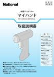
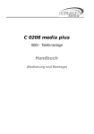
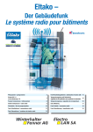
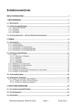
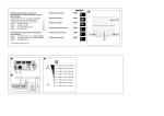
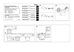
05-190
1. WETTELIJKE WAARSCHUWINGEN
- Lees de volledige handleiding vóór installatie en ingebruikname.
- De installatie dient te worden uitgevoerd door een erkend installateur en met inachtname van de geldende
voorschriften.
- Deze handleiding dient aan de gebruiker te worden overhandigd. Zij moet bij het dossier van de elektrische installatie worden gevoegd en dient te worden overgedragen aan eventuele nieuwe eigenaars. Bijkomende exemplaren
zijn verkrijgbaar via de Niko-website of -supportdienst.
- Bij de installatie dient rekening gehouden te worden met (lijst is niet limitatief):
- de geldende wetten, normen en reglementen;
- de stand van de techniek op het ogenblik van de installatie;
- het feit dat een handleiding alleen algemene bepalingen vermeldt en dient gelezen te worden binnen het kader
van elke specifieke installatie;
- de regels van goed vakmanschap.
- Bij twijfel kan u de supportdienst van Niko raadplegen of contact opnemen met een erkend controleorganisme.
Support België:
Support Nederland:
tel. + 32 3 760 14 82
tel. + 31 183 64 06 60
website: http://www.niko.be
website: http://www.niko.nl
e-mail: [email protected]
e-mail: [email protected]
In geval van defect kan u uw product terugbezorgen aan een erkende Niko-groothandel samen met een duidelijke
omschrijving van uw klacht (manier van gebruik, vastgestelde afwijking…).
2. BESCHRIJVING
De telefooninterface 05-190 is een toestel waarmee u via een analoog telefoonnet vanop afstand een verbruiker
kan schakelen. De bediening gebeurt met toonkeuze (dual tone multifrequency – DTMF) via de telefoontoetsen
of via een DTMF-handzender. Terugmeldingstonen geven informatie over de schakeltoestand. De schakelfunctie
kan via de telefoonlijn, via de ingebouwde toets of via een externe toets uitgevoerd worden. De schakelfunctie
via de telefoonlijn is beveiligd met een code van 4-cijfers. De 1-kanaal telefooninterface wordt ingebouwd in een
4U-modulaire behuizing.
3. INSTALLATIE
Inbouw en installatie van de telefooninterface mogen enkel door een gespecialiseerd elektrotechnicus uitgevoerd
worden. Om te beantwoorden aan de algemene veiligheidsvoorschriften voor telecommunicatieapparatuur en
elektromagnetische storingen te vermijden, moet de norm resp. prEN 50174-2:1998, par. 5.4 en 5.5 in acht genomen worden. De installatie moet uitgevoerd worden conform de nationaal geldende installatievoorschriften.
Sluit de telefooninterface als volgt aan:
1 Sluit de telefooninterface aan op de telefooncontactdoos van het lokale telefoonbedrijf. Verbind de aansluitklemmen La en Lb van de telefooninterface via een telefoonkabel met de aansluitklemmen a2 en b2. De telefooninterface kan ook achteraan op de telefooncentrale aangesloten worden. Om het aansluiten van de draden te
vergemakkelijken, kan u de connector verwijderen door hem naar voor te trekken.
2 Verbind de aansluitingen L1 en N met het net (230V). Per klem kan max. 1 x 1,5mm² aangesloten worden.
3 Sluit het schakelcontact aan volgens één van onderstaande aansluitschema’s.
4. WERKING EN GEBRUIK
Na de oproep en oproepbeantwoording hoort u vier korte tonen. U kan nu de code van 4 cijfers invoeren. Als u
de juiste code ingevoerd hebt, hoort u een lange bevestigingstoon. Vanaf nu kunnen schakelfuncties uitgevoerd
worden:
- Druk op 1 om het schakelcontact te sluiten. U hoort een bevestigingstoon.
- Druk op 0 om het schakelcontact te openen. U hoort twee korte bevestigingstonen.
- Druk op 6 om het schakelcontact gedurende 0,5s te sluiten (impulsfunctie). Was het schakelcontact al gesloten, dan
wordt het vóór het uitvoeren van de impulsfunctie gedurende 3s geopend en blijft het nadien ook geopend. U hoort
twee korte bevestigingstonen.
- Druk op # om de actuele schakelstatus op te vragen. U hoort een lange toon (contact gesloten) of een korte
toon (contact open).
Aansluiting van de telefooninterface: direct aansturen van een verbruiker (S105190)
Telefoonlijn in
- Druk op * om de telefoonverbinding te beëindigen (inhaken).
- Als u een verkeerde code ingevoerd hebt, hoort u vier korte signaaltonen.
- Als u drie keer een verkeerde code invoert, wordt de verbinding verbroken.
Opmerkingen
Als u code 1111 instelt, vraagt de telefooninterface geen geheime code. De schakelfuncties kunnen dan onmiddellijk uitgevoerd worden. Als er een telefoonverbinding is, maar de telefooninterface gedurende 15s geen
selectiecijfer ontvangt, wordt de verbinding verbroken.
De telefooninterface kan eventueel ook met 12V i.p.v. 230V (ev. noodstroomvoorziening) gevoed worden. In dit
geval moet de voedingsspanning op de klemmen 12V (plus) en ⊥ (min) aangelegd worden.
Instellingen op de telefooninterface
Stel het aantal beltonen in met de rechterdraaischakelaar met behulp van een schroevendraaier. Dit aantal kan
ingesteld worden van 1 tot 9. Bij 0 blijft het toestel uitgeschakeld. De fabrieksinstelling is 9. De telefooninterface
beantwoordt de oproep automatisch. Activeer de automatische oproepbeantwoording met de rechtertoets ‘Off
Hook’. De overeenkomstige LED licht op. Zolang de telefooninterface verbonden is, knippert de groene LED (‘in
gesprek’). U kan het schakelcontact ook manueel aan- of uitschakelen met de ‘Aan’-knop. De overeenkomstige
LED geeft aan of het toestel aan- of uitgeschakeld is.
Het codenummer instellen
Stel de code van 4 cijfers in met behulp van de vier draaischakelaars. De fabrieksinstelling is ‘0000’.
5. TECHNISCHE GEGEVENS
Netspanning: ................................ 230V +6/-10 %
Schakeluitgangen: ........................ relaiscontact van max. 10A, 230 V AC (ohmse belasting)
Opgenomen vermogen: ................ max. 1,5VA
Belfrequentie: ............................... 23Hz tot 54Hz
Afmetingen: .................................. L72 mm x B90 mm x H65 mm (4U)
Bedrijfstemperatuur: ..................... -5 tot 45°C
Beschermingsklasse: ................... IP20
Toelating
De vereiste conformiteitskeuringsprocedures voor de telefooninterface 05-190 werden uitgevoerd. Dit toestel werd
conform het Besluit 98/482/EEG van de Europese Raad voor heel Europa goedgekeurd voor de aansluiting als
losse eindapparatuur op het openbare telefoonnet. Op grond van de verschillen die er bestaan tussen de openbare
telefoonnetten van verschillende landen, vormt deze goedkeuring evenwel geen garantie voor een feilloze werking
van het toestel op elk aansluitpunt. De telefooninterface 05-190 is geproduceerd volgens het keuringsbesluit voor
telecommunicatie van 20/08/97, geregistreerd door CETECOM ICT Services GmbH als erkende instantie met EURegistratienummer 0682. Steunend op Richtlijn 98/13/EEG van het Europees Parlement en de Raad van 12/02/98,
is de conformiteit met de volgende technische voorschriften en richtlijnen van de Europese Gemeenschap en in
het toepassingsgebied van de telecommunicatieverordening vervuld.
Voorschriften en richtlijnen: CTR 21 — BAPT 223 ZV 5 — 73/23/EEG — 89/336/EEG
6. GARANTIEBEPALINGEN
- Garantietermijn: twee jaar vanaf leveringsdatum. Als leveringsdatum geldt de factuurdatum van aankoop van het
goed door de consument. Indien geen factuur voorhanden is, geldt de productiedatum.
- De consument is verplicht Niko schriftelijk over het gebrek aan overeenstemming te informeren, uiterlijk binnen
de twee maanden na vaststelling.
- In geval van een gebrek aan overeenstemming van het goed heeft de consument recht op een kosteloze herstelling
of vervanging, wat door Niko bepaald wordt.
- Niko is niet verantwoordelijk voor een gebrek of schade als gevolg van een foutieve installatie, oneigenlijk of
onachtzaam gebruik of verkeerde bediening of transformatie van het goed.
- De dwingende bepalingen van de nationale wetgevingen betreffende de verkoop van consumptiegoederen en de
bescherming van de consumenten van de landen waarin Niko rechtstreeks of via zuster/dochtervennootschappen, filialen, distributeurs, agenten of vaste vertegenwoordigers verkoopt, hebben voorrang op bovenstaande
bepalingen.
Aansluitschema van de telefooninterface op de ingangen A en B van de Nikobusmodule
(S205190)
Telefoonlijn uit
Telefoonlijn in
Telefoonlijn uit
a
b
12V
Lb
S1
La
b
12V
a
S1
La
Let op:
Maximale belasting:
10A (ohms)
Lb
Externe schakeltoets
(optioneel)
RF
901
901
78
78
78
78
05-190
230V~
L1 N
230V~
456
456
456
456
N
L
N
1
2
L1
N
3
4
5
6
6
µ
N
N
7
8
9
10
11
12
set
A B N 10 11 12 0V
feedback led
m1
m2
m3
m4
m5
mode
N
L
L4
L5
L6
10A 230V~ 50Hz
N
L
10A 230V~ 50Hz
program
05-000-01
F01
2345
select
B1 B2
bus
T1
11
12
13
14
15
230V~
ABCE
78
456
78
456
78
456
78
456
78
901
456
23
05-190
IR
Rings
901
23
23
901
0682 X
230V~
L1 N
L1
N
23
23
23
23
23
23
0682 X
901
456
Rings
901
78
Code-Nr.
901
m8
18
901
Off hook
m6
m7
901
On
6789
Off hook
23
On
Code-Nr.
230V~
Alternatief kan het schakelcontact ook op de binaire
ingangen 05-054 en 05-055
aangesloten worden.
BUSDRUKKNOPPEN
en INTERFACES
Dit product is een deel van het Nikobus-domoticasysteem. Voor een beschrijving van het totaalsysteem verwijzen
wij u naar de Nikobus-catalogus en -installatiecursus.
230V~ 50Hz
L
N
230V~
10A
NV
SA Industriepark West 40, B-9100 Sint-Niklaas — Tel. +32 3 760 14 70 — Fax +32 3 777 71 20 — E-mail: [email protected] — www.niko.be — www.niko.nl — www.niko.fr
PM142-099R06054
05-190
1. PRESCRIPTIONS LEGALES
- Lisez entièrement le mode d’emploi avant toute installation et mise en service.
- L’installation doit être effectuée par un installateur agréé et dans le respect des prescriptions en vigueur.
- Ce mode d’emploi doit être remis à l’utilisateur. Il doit être joint au dossier de l’installation électrique et être
remis à d’éventuels autres propriétaires. Des exemplaires supplémentaires peuvent être obtenus sur le site web
ou auprès du service ‘support Niko’.
- Il y a lieu de tenir compte des points suivants avant l’installation (liste non limitative):
- les lois, normes et réglementations en vigueur;
- l’état de la technique au moment de l’installation;
- ce mode d’emploi qui doit être lu dans le cadre de toute installation spécifique;
- les règles de l’art.
- En cas de doute, vous pouvez appeler le service ‘support Niko’ ou vous adresser à un organisme de contrôle
reconnu.
Support Belgique:
Support France:
+ 32 3 760 14 82
+ 33 4 78 66 66 20
site web: http://www.niko.be
site web: http://www.niko.fr
e-mail: [email protected]
e-mail: [email protected]
En cas de défaut de votre appareil, vous pouvez le retourner à un grossiste Niko agréé, accompagné d’une description
détaillée de votre plainte (manière d’utilisation, divergence constatée…).
2. DESCRIPTION
L’interface téléphonique est un appareil qui permet de commuter un consommateur par le réseau téléphonique
analogue. La commande s’effectue par un 'téléphone à touches' (dual tone multi-frequency - DTMF), soit par
l’intermédiaire du clavier du téléphone, soit par un émetteur portable DTMF. La signalisation de l’état de commutation des relais de sortie s’effectue par signaux sonores. Les fonctions d’enclenchement peuvent être exécutées
tant par l’intermédiaire de la ligne téléphonique que par des touches situées sur l’appareil ou par l’intermédiaire
de contacts externes. La fonction de commutation par l’intermédiaire de la ligne téléphonique est protégée par un
code à 4 chiffres. L’interface téléphonique à 1 canal est prévue pour fixation sur rail DIN, largeur de 4 modules.
3. INSTALLATION
L’encastrement et l’installation de l’interface téléphonique ne peuvent être réalisés que par un électricien spécialisé. Pour répondre aux mesures générales de sécurité relatives aux télécommunications et pour éviter les
parasites électromagnétiques, il y a lieu de tenir compte de la norme prEN 50174-2:1998, paragraphes 5.4 et 5.5.
Les instructions de sécurité nationales en vigueur doivent être respectées.
1. Raccorder l’interface téléphonique à la ligne téléphonique, en plaçant un câble téléphonique entre les bornes La
et Lb de l’interface téléphonique et les bornes a2 et b2. Au lieu d’être raccordée au réseau, l’interface téléphonique
peut également être reliée au poste secondaire d’un central téléphonique. Pour faciliter l’installation des fils de
raccordement de l’appareil, le connecteur peut être extrait (tirer vers l’avant).
2. Relier les raccordements L1 et N au réseau d’alimentation (230V). Les bornes de raccordement sont conçues
pour des fils d’une section max. de 1 x 1,5 mm².
3. Raccorder le contact de commutation conformément aux schémas de raccordement repris ci-dessous.
4. FONCTIONNEMENT ET UTILISATION
Après les sonneries et la prise de ligne, 4 courtes tonalités de signalisation retentissent. Introduisez le code
à 4 chiffres. Si le code introduit est correct, une longue tonalité de confirmation retentit. Il est alors possible
d’exécuter les fonctions d’enclenchement avec les chiffres correspondants.
- Choisissez le chiffre 1 pour fermer le contact. Une longue tonalité de confirmation retentit.
- Choisissez le chiffre 0 pour ouvrir le contact. Deux courtes tonalités de confirmation retentissent.
- Choisissez le chiffre 6 pour fermer le contact durant 0,5s (fonction d’impulsion). Dans la mesure où le contact
était fermé, il est ouvert durant 3s avant exécution de la fonction d’impulsion, et il reste ensuite ouvert. Deux
courtes tonalités de confirmation retentissent.
- Enfoncez la touche # pour appeler l’état actuel de commutation. Une tonalité longue (contact fermé) ou courte
(contact ouvert) retentit.
- Enfoncez la touche * pour mettre fin à la liaison téléphonique (raccrocher).
- Si le code est incorrect, 4 courtes tonalités de signalisation retentissent.
Raccordement de l’interface téléphonique: commande directe d’un appareil (S105190)
Ligne téléphonique sortie
Ligne téléphonique
entrée
- Après 3 tentatives fautives, la liaison est coupée.
Remarques
Si vous sélectionnez le code 1111, le système outrepasse la phase de vérification du code. Les fonctions
d’enclenchement peuvent alors être exécutées immédiatement. Si la ligne téléphonique a décroché et qu’aucun
code n’est reçu avant 15s, l’appareil interrompt la ligne téléphonique.
L’interface téléphonique peut éventuellement aussi être alimentée en 12V (alimentation de secours) au lieu d’en
230V. La tension d’alimentation doit alors être raccordée aux bornes 12V (plus) et ⊥ (moins).
Réglages de l’interface téléphonique
L’interrupteur rotatif de droite permet, à l’aide d’un tournevis, de programmer le nombre de sonneries suite
auxquelles l’interface téléphonique prend automatiquement la ligne. Ce nombre peut être réglé entre 1 et 9. Si le
nombre de sonneries est de 0, l’appareil reste à l’état de repos. Le réglage d’usine est 9.
Enfoncez la touche de droite ‘Off Hook’ pour que l’interface téléphonique prenne automatiquement la ligne. La
LED correspondante s’allume pour confirmer l’activation. Pendant que l’interface téléphonique occupe la ligne
téléphonique, la LED verte clignote (ligne occupée). La touche ON permet d’enclencher ou de déclencher manuellement le contact. La LED fournit des informations sur l’état de connexion en cours.
Programmation du code
La programmation du code à 4 chiffres s’effectue au moyen de 4 interrupteurs rotatifs. Le code réglé à la sortie
d’usine est 000.
5. CARACTERISTIQUES TECHNIQUES
Tension réseau: ............................ 230V +6/-10%
Sorties de commande: ................. contact par relais de max. 10A, 230V~ (charge ohmique)
Puissance absorbée: .................... max. 1,5VA
Fréquence de sonnerie: ................ 23Hz à 54Hz
Dimensions: ................................. L72 mm x I90 mm x H65 mm (4U)
Température ambiante (ta): ........... -5 à 45°C
Degré de protection: ..................... IP20
Agrément
Les procédures nécessaires à l’évaluation de la conformité de l’interface téléphonique 05-190 ont été exécutées.
Cet appareil a été agréé suivant la Décision 98/482/CE du Conseil européen, pour la mise en connexion,
comme terminal individuel, sur le réseau téléphonique public. En raison des disparités qui existent entre les
réseaux officiels de téléphonie de différents états, cet agrément ne constitue toutefois pas, par lui-même, une
garantie d’efficacité d’utilisation de l’appareil à toute prise terminale du réseau. L’interface téléphonique 05-190
est fabriquée en respectant un système très élaboré de garantie de qualité et est enregistré, conformément au
paragraphe 12 du règlement sur l’agrément des télécommunications du 20/08/97, par les CETECOM ICT Services GmbH, organisme notifié, avec le numéro caractéristique CE 0682. Sur base de la directive 98/13/CE du
Parlement européen et du Conseil du 12/02/98, la conformité est garantie selon les prescriptions techniques et
directives, citées ci-après, de la Communauté européenne, et dans le domaine d’application du règlement sur les
télécommunications.
Prescriptions et directives: CTR 21 — BAPT 223 ZV 5 — 73/23/EEG — 89/336/EEG
6. DISPOSITIONS DE GARANTIE
- Délai de garantie: 2 ans à partir de la date de livraison. La date de la facture d’achat par le consommateur fait
office de date de livraison. Sans facture disponible, la date de fabrication est seule valable.
- Le consommateur est tenu de prévenir Niko par écrit de tout manquement à la concordance des produits dans
un délai max. de 2 mois après constatation.
- Au cas ou pareil manquement serait constaté, le consommateur a droit à une réparation gratuite ou à un
remplacement gratuit selon l’avis de Niko.
- Niko ne peut être tenu pour responsable pour un défaut ou des dégâts suite à une installation fautive, à une
utilisation contraire ou inadaptée ou à une transformation du produit.
- Les dispositions contraignantes des législations nationales ayant trait à la vente de biens de consommation et la
protection des consommateurs des différents pays où Niko procède à la vente directe ou par entreprises interposées,
filiales, distributeurs, agents ou représentants fixes, prévalent sur les dispositions susmentionnées.
Raccordement de l’interface téléphonique aux entrées A et B du module Nikobus (S205190)
Ligne téléphonique
entrée
Ligne téléphonique sortie
Alternativement le contact
pour la commande peut être
raccordé aux entrées binaires 05-054 et 05-055.
a
b
12V
Lb
S1
La
b
12V
a
S1
La
Attention:
charge maximum:
10A (ohmique)
Lb
Contact externe
(optionnel)
RF
901
901
78
78
78
78
05-190
230V~
L1 N
230V~
456
456
456
456
N
L
N
1
2
L1
N
3
4
5
6
6
µ
N
N
7
8
9
10
11
12
set
A B N 10 11 12 0V
feedback led
m1
m2
m3
m4
m5
mode
N
L
L4
L5
L6
10A 230V~ 50Hz
N
L
10A 230V~ 50Hz
program
05-000-01
F01
2345
select
B1 B2
bus
T1
11
12
13
14
15
230V~
ABCE
78
456
78
456
78
456
78
456
78
901
456
23
05-190
IR
Rings
901
23
23
L1
N
901
0682 X
230V~
L1 N
230V~
23
23
23
0682 X
901
456
Rings
901
23
23
23
901
78
Code-Nr.
Code-Nr.
m8
18
901
Off hook
m6
m7
901
On
6789
Off hook
23
On
BOUTONS-POUSSOIRS
et INTERFACES
Ce produit fait partie du système domotique Nikobus. Pour la description du système complet veuillez consulter
le catalogue Nikobus et le manuel d’installation.
230V~ 50Hz
L
N
230V~
10A
NV
SA Industriepark West 40, B-9100 Sint-Niklaas — Tel. +32 3 760 14 70 — Fax +32 3 777 71 20 — E-mail: [email protected] — www.niko.be — www.niko.nl — www.niko.fr
PM142-099R06054
05-190
Dieses Produkt ist ein Teil der Nikobus Gebäudesystemtechnik. Für eine Beschreibung des gesamten Systems verweisen wir auf den Nikobus-Katalog sowie die Nikobus-Schulungsunterlage.
1. GESETZLICHE BESTIMMUNGEN
- Lesen Sie vor der Montage und Inbetriebnahme die vollständige Gebrauchsanleitung.
- Die Installation darf ausschließlich von einem Fachmann des Elektrohandwerks unter Berücksichtigung der geltenden
Vorschriften vorgenommen werden.
- Übergeben Sie dem Benutzer diese Gebrauchsanleitung. Sie ist den Unterlagen der elektrischen Anlage beizufügen und
muss auch eventuellen neuen Besitzern übergeben werden. Zusätzliche Exemplare erhalten Sie über unsere Website
oder unseren Servicedienst.
- Bei der Installation müssen Sie u.a. Folgendes berücksichtigen:
- die geltenden Gesetze, Normen und Vorschriften;
- den Stand der Technik zum Zeitpunkt der Installation;
- diese Gebrauchsanleitung die im Zusammenhang mit jeder spezifischen Anlage gesehen werden muss;
- die Regeln fachmännischen Könnens.
- Sollten Sie Fragen haben, können Sie sich an die Niko-Hotline oder an eine anerkannte Kontrollstelle wenden:
Web-site: http://www.niko.be; E-Mail: [email protected];
Hotline Belgien: +32 3 760 14 82
Hotline Moeller Deutschland:
Berlin: +49 30 701902-46
Hamburg: +49 40 75019-281
Düsseldorf: +49 2131 317-37
Frankfurt a.M.: +49 69 50089-263
Stuttgart: +49 711 68789-51
München: +49 89 460 95-218
Mail: [email protected]
Österreich:
Moeller Gebäudeautomation UG Schrems 0043-2853-702-0
Hotline Slowakei: +421 263 825 155 – E-mail: [email protected]
Im Falle eines Defektes an Ihrem Niko-Produkt, können Sie dieses mit einer genauen Fehlerbeschreibung
(Anwendungsproblem, festgestellter Fehler, usw.) an Ihren Moeller- oder Niko-EGH zurückbringen.
2. BESCHREIBUNG
Das Telefoninterface 05-190 ist ein Fernschaltgerät, mit dem über das Telefonnetz ein Verbraucher geschaltet werden
kann. Die Steuerung wird mit dem Mehrfrequenz-Wahlverfahren (MFV) durchgeführt. Dies erfolgt entweder über die
Telefontastatur, über externe Taster oder über einen MFV-Handsender. Unterschiedliche Rückmeldetöne informieren
über die verschiedenen Schaltzustände. Die Schaltfunktion kann über die Telefonleitung, einen eingebauten Taster oder
externen Taster ausgeführt werden. Die Schaltfunktion über die Telefonleitung ist mit einer 4-stelligen Codenummer
gesichert. Maße des Telefoninterfaces mit 1 Kanal: REG-Gehäuse 4TE breit.
3. INSTALLATION
Der Einbau und die Installation des Telefoninterfaces darf nur durch eine Elektrofachkraft erfolgen. Um die allgemeinen
Sicherheitsbestimmungen für Fernmeldeanlagen zu erfüllen und um Störbeinflussungen zu vermeiden, muss die prEN
50174-2:1998, Abschnitte 5.4 und 5.5 beachtet werden. Das Telefoninterface muss installiert werden wie in den national gültigen Installationsvorschriften beschrieben.
Schließen Sie das Telefoninterface wie folgt an:
1. Schließen Sie das Telefoninterface an den Übergabepunkt des lokalen Telefonnetzes an. Verbinden Sie die Anschlussklemmen La und Lb des Telefoninterfaces durch ein Installationskabel mit den Anschlussklemmen a2 und b2. Statt an
den Übergabepunkt kann das Telefoninterface auch an die Nebenstelle des Telefonnetzes angeschlossen werden. Die
obere Steckklemmleiste wird zur einfacheren Installation der Anschlussdrähte vom Gerät nach oben gezogen.
2. Verbinden Sie die Anschlüsse L1 und N mit dem 230V-Versorgungsnetz. Die Anschlussklemmen sind für Leistungen bis max. 1 x 1,5 mm² ausgelegt.
3. Schließen Sie die Leitung für die Verbraucher entsprechend einem der nachstehenden Anschlussbilder an.
4. ARBEITSWEISE UND ANWENDUNG
Nach Anwahl und Belegen werden als Aufforderung zur Eingabe der vierstelligen Codenummer vier kurze Signaltöne
zum Anrufer übermittelt. Bei Eingabe der richtigen Codenummer wird ein langer Bestätigungston übermittelt. Danach
können. Schaltfunktionen mit den entsprechenden Ziffern ausgeführt werden.
- Drücken Sie 1 um den angeschlossenen Verbraucher zu schließen. Es ertönt ein langer Bestätigungston.
- Drücken Sie 0 um den angeschlossenen Verbraucher zu öffnen. Es ertönen zwei kurze Bestätigungstöne.
- Drücken Sie 6 um den angeschlossene Verbraucher für 0,5s zu schließen (Stromstoßfunktion). Falls der Verbraucher
schon geschlossen war, wird er vor dem Ausführen der Stromstoßfunktion für 3s geöffnet und bleibt anschließend
Telefonleitung ein
Telefonleitung aus
Anschluss des Telefoninterfaces mit den Eingängen A und B des Nikobusmoduls
(S205190)
Telefonleitung aus
Der Verbraucher kann auch
mit den Binäreingängen 05054 und 05-055 verbunden
werden.
Telefonleitung ein
a
b
12V
Lb
S1
La
b
12V
a
S1
La
Achtung:
max. Last: 10A
(ohmsch)
Lb
Externer Schalter
(Option)
RF
901
901
78
78
78
78
05-190
230V~
L1 N
230V~
456
456
456
456
N
L
N
1
2
L1
N
3
4
5
6
6
µ
N
N
7
8
9
10
11
12
set
A B N 10 11 12 0V
feedback led
m1
m2
m3
m4
m5
mode
N
L
L4
L5
L6
10A 230V~ 50Hz
N
L
10A 230V~ 50Hz
program
05-000-01
F01
2345
select
B1 B2
bus
T1
11
12
13
14
15
230V~
ABCE
78
456
78
456
78
456
78
456
78
901
456
23
05-190
IR
Rings
901
23
23
L1
N
901
0682 X
230V~
L1 N
230V~
23
23
23
0682 X
901
456
Rings
901
23
23
23
901
78
Code-Nr.
Code-Nr.
m8
18
901
Off hook
m6
m7
901
On
6789
Off hook
23
On
BUSDRUCKTASTER
und INTERFACES
Anschluss des Telefoninterfaces: Direktansteuerung eines Verbrauchers (S105190)
geöffnet. Es ertönen zwei kurze Bestätigungstöne.
- Drücken Sie # um den aktuellen Schaltzustand abzufragen. Es ertönt ein langer Ton (Gerät ein) oder ein kurzer Ton
(Gerät aus).
- Drücken Sie * um die Telefonverbindung zu beenden (auflegen).
- Bei einer fehlerhaften Codenummer werden vier kurze Signaltöne gesendet.
- Nach dreimaliger falscher Eingabe der Codenummer wird die Verbindung abgebrochen.
Besonderheiten
Bei Einstellung der Codenummer 1111 wird die Überprüfung der Codenummer übergangen, d.h. sofort nach Belegung wird ein langer Bestätigungston gesendet und Schaltfunktionen können sofort ausgeführt werden. Hat das
Telefoninterface die Telefonleitung belegt und wird 15s lang keine Wahlziffer empfangen, so schaltet sich das Gerät
von der Telefonleitung ab.
Die Stromversorgung vom Telefoninterface kann wahlweise auch mit 12V (Notstromversorgung) erfolgen. Die Versorgungsspannung ist dann an die Klemmen 12V (plus) und ⊥ (minus) anzulegen.
Einstellungen am Telefoninterface
Mit dem rechten Codierschalter wird mit einem Schraubendreher die Rufanzahl eingestellt, bei der das Telefoninterface
automatisch die Leitung belegt. 1 bis 9 Rufe sind einstellbar. Bei der Rufanzahl 0 bleibt das Gerät im Ruhezustand.
Die Werkeinstellung ist 9. Mit dem rechten Taster ‚Off Hook’ wird das Gerät für automatische Rufannahme vorbereitet,
d.h. wenn die dazugehörige LED leuchtet, schaltet sich das Gerät mit der voreingestellten Rufanzahl an den jeweiligen
Telefonanschluss auf Empfangsbereitschaft. Solange das Telefoninterface die Telefonleitung belegt, blinkt die grüne
LED (‚besetzt’). Mit dem Taster ‚Ein’ wird der am Schaltausgang angeschlossene Verbraucher ein- bzw. ausgeschaltet.
Die dazugehörige LED informiert über den jeweiligen Schaltzustand.
Einstellen der Codenummer
Die Einstellung der vierstelligen Codenummer erfolgt mittels vier Codierschaltern.
Im Auslieferungszustand ist als Codenummer ‚0000’ eingestellt.
5 .TECHNISCHE DATEN
Netzspannung: ................................ 230V +6/-10%
Schaltausgänge: .............................. potentialfreier Relaiskontakt max. 10A, 230V AC (ohmsche Last)
Leistungsaufnahme: ........................ max. 1,5VA
Ruffrequenz: .................................... 23Hz bis 54Hz
Abmessungen: ................................ L72 x B90 x H65mm
Temperaturbereich Betrieb: ............. -5 bis 45°C
Schutzart: ......................................... IP20
Zulassung
Die erforderlichen Konformitätsbewertungsverfahren für das Telefoninterface 05-190 wurden duchgeführt. Dieses
Gerät wurde gemäß der Entscheidung 98/482/EG des Rates europaweit zur Anschaltung als einzelne Endeinrichtung an
das öffentliche Fernsprechnetz zugelassen. Aufgrund der zwischen den öffentlichen Fernsprechnetzen verschiedener
Staaten bestehenden Unterschiede stellt diese Zulassung an sich jedoch keine Gewähr für einen erfolgreichen Betrieb
des Gerätes an jedem Netzabschlusspunkt dar. Das Telefoninterface 05-190 wird im Rahmen eines umfassenden Qualitätssicherungssystems gefertigt und ist gemäß der Telekommunikationszulassungsverordenung vom 20.08.97 durch
die CETECOM ICT Services GmbH, als Bekannte Stelle, mit der EU-Kennnr. 0682 registriert. Gestützt auf die Richtlinie
98/13/EG des Europäischen Parlamentes und des Rates vom 12.02.98 ist die Konformität mit den nachfolgenden
technischen Vorschriften und Richtlinien der Europäischen Gemeinschaft und im Anwendungsbereich der Telekommunikationsverordnung erfüllt.
Vorschriften und Richtlinien: CTR 21 - BAPT 223 ZV 5 – 73/23/EEG – 89/336/EEG
6. GARANTIEBESTIMMUNGEN
- Garantiezeitraum: Zwei Jahre ab Lieferdatum. Als Lieferdatum gilt das Rechnungsdatum zu dem der Endkunde das
Produkt gekauft hat. Falls keine Rechnung mehr vorhanden ist, gilt das Produktionsdatum.
- Der Endkunde ist verpflichtet, Niko über den festgestellten Mangel innerhalb von zwei Monaten zu informieren.
- Im Falle eines Mangels an dem Produkt hat der Endkunde das Recht auf eine kostenlose Reparatur oder Ersatz. Dies
wird von Niko entschieden.
- Niko ist nicht für einen Mangel oder Schaden verantwortlich, der durch unsachgemäße Installation, nicht bestimmungsgemäßen oder unvorsichtigen Gebrauch oder falsche Bedienung oder Anpassen/Ändern des Produktes entsteht.
- Die zwingenden Vorschriften der nationalen Gesetzgebung bezüglich des Verkaufs von Konsumgütern und der Schutz
des Kunden in den Ländern in denen Niko direkt oder über seine Tochtergesellschaften, Filialen, Distributoren,
Handelsvertretungen oder Vertretern verkauft, haben Vorrang vor den obigen Bestimmungen.
230V~ 50Hz
L
N
230V~
10A
NV
SA Industriepark West 40, B-9100 Sint-Niklaas — Tel. +32 3 760 14 70 — Fax +32 3 777 71 20 — E-mail: [email protected] — www.niko.be — www.niko.nl — www.niko.fr
PM142-099R06054
05-190
This product is part of the Nikobus home automation system. For a description of the complete system, please
refer to the Nikobus catalogue and installation manual.
1. LEGAL WARNINGS
- Read the complete manual before attempting installation and activating the system.
- The installation has to be carried out by a registered installer and in compliance with the statutory regulations.
- This user manual has to be handed over to the user. It has to be included in the electrical installation file and
has to be passed on to any new owners. Additional copies are available on the Niko website or via the support
service.
- During installation, the following has to be taken into account (not limited to list below):
- The statutory laws, standards and regulations;
- The state of the art technique at the moment of installation;
- This user manual, which must be read within the scope of each specific installation, only states general regulations;
- The rules of proper workmanship
- In case of questions, you can consult Niko’s support service or contact a registered control organisation.
Support Belgium:
Support Slovakia:
+32 3 760 14 82
+421 263 825 155
website : http://www.niko.be
e-mail: [email protected]
e-mail: [email protected]
In case of a defect, you can return your product to a registered Niko wholesaler, together with a clear description
of your complaint (Conditions of use, stated defect…).
2. DESCRIPTION
The telephone interface 05-190 is an appliance with which you can remotely switch a device via an analog telephone network. The control is either carried out with a DTMF-telephone (DTMF = dual tone multifrequency) or
with a DTMF hand-held transmitter. Feedback tones give information about the switching status. The switching
function can be carried out via the telephone line, a built-in push button or and external push button. The switching function via the telephone line is protected by a 4-digit code. The 1-channel telephone interface is flush
mounted into a 4U modular cabinet.
3. INSTALLATION
The installation has to be carried out by a specialized electrotechnician. In order to answer to the general requirements for telecommunication and EMC, the standard prEN 50174-2:1998, par. 5.4 and 5.5 has to be taken into
account. The entire installation has to be in accordance with the national installation requirements.
Connect the telephone interface as follows:
1. Connect the telephone interface to the telephone outlet of your local telephone network. Connect connection
terminals La an Lb of the telephone interface to connection terminals a2 and b2 via a telephone cable. The telephone interface can also be connected to the telephone exchange at the back. To simplify the connection, you can
remove the connector by pulling it forward.
2. Connect L1 and N to the mains (230V). Per terminal, max. 1 x 1,5mm² can be connected.
3. Connect the switching contact according to one of the wiring diagrams mentioned bellow.
3. OPERATION AND USE
After the call and call answering, you hear 4 short beeps. You can now enter the 4-digit code. If your entry is correct, you hear a long beep in confirmation. Switching functions can now be carried out:
- Press 1 to close the switching contact. You hear a beep in confirmation.
- Press 0 to open the switching contact. You hear 2 beeps in confirmation.
- Press 6 to close the switching contact for 0.5s (impuls function). If the switching contact was already closed, it
will be opened for 3s before the impuls function is carried out and stays open afterwards. You hear 2 short beeps
in confirmation.
- Press # to retrieve the current switching status. You hear a long beep (contact closed) or a short beep (contact
open).
- Press * to wind up the telephone connection (put the receiver down).
- If you have entered a wrong code, you hear 4 short beeps.
- If you enter a wrong code thrice, the connection is wound up.
Telephone line in
Telephone line out
Settings on the telephone interface
You can set the number of ring tones by means of the right rotary switch using a screwdriver. This number can be
set from 1 to 9. At 0, the interface remains switched off. The default setting is 9. The telephone interface automatically answers the call. Activate the automatic answering by means of the right key ‘Off Hook’. The corresponding
LED lights. For as long as the telephone interface is connected, the green LED blinks (‘busy’). You can also switch
the switching contact on or off manually by means of the ‘On’ key. The corresponding LED indicates whether or
not the appliance has been switched off.
Setting the code
Enter the 4-digit code by means of the 4 rotary switches. The default setting is ‘0000’.
5. TECHNICAL DATA
Mains voltage: ............................. 230V +6/-10%
Switching outputs: ....................... relay contact of max. 10A, 230V AC (ohmic load)
Power consumption: .................... max. 1,5VA
Ringing frequency: ....................... 23Hz to 54Hz
Dimensions: ................................. L72mm x W90mm x H65mm (4U)
Operating temperature: ................. -5 to 45°C
Protection class: .......................... IP20
Approvals
The required conformity evaluation processes for the telephone interface 05-190 have been carried out. The
equipment has been approved in accordance with Council Decision 98/482/EC for Pan-European single terminal
connection to the public switched telephone network (PSTN). However, due to differences between the individual
PSTNs provided in different countries, the approval does not, of itself, give an unconditional assurance of successful operation on every PSTN network termination point. The telephone interface 05-190 is being manufactured
within a comprising quality assurance system and is according to the telecommunications approval regulation
from 20.8.1997 registred by CETECOM ICT Services GmbH (notified body with European code no. 0682). Based
on the European directive 98/13/EC of the European parliament and the Council Decision from 12.02.1998, the
conformity of the following technical rules and guidelines of the European Community and the telecommunications approval regulation are confirmed.
Rules and guidelines: CTR 21 – BAPT 223 ZV 5 – 73/23/EC – 89/336/EC
6. GUARANTEE PROVISIONS
- Period of guarantee: 2 years from date of delivery. The delivery date is the invoice date of purchase of the product
by the consumer. If there is no invoice, the date of production applies.
- The consumer is obliged to inform Niko in writing about the defect, within two months after stating the defect.
- In case of a failure to conform, the consumer has the right to a repair or replacement (decided by Niko) free of
charge.
- Niko cannot be held liable for a defect or damage as a result of an incorrect installation, improper or careless
use or wrong usage or transformation of the goods.
- The compulsory regulations of the national legislation concerning the sales of consumer goods and the protection
of the consumers in the countries where Niko sells, directly or via sister or daughter companies, chain stores,
distributors, agents or permanent sales representatives, take priority over the rules and regulations mentioned
above.
Wiring diagram of the telephone interface on the inputs A and B of the Nikobus unit (S205190)
Telephone line in
Telephone line out
The switch point can also be
connected to the binary inputs 05-054 and 05-055.
a
b
12V
Lb
S1
La
b
12V
a
S1
La
Achtung:
max. Last: 10A
(ohmsch)
Lb
External switch
point (optional)
RF
901
901
78
78
78
78
05-190
230V~
L1 N
230V~
456
456
456
456
N
L
N
1
2
L1
N
3
4
5
6
6
µ
N
N
7
8
9
10
11
12
set
A B N 10 11 12 0V
feedback led
m1
m2
m3
m4
m5
mode
N
L
L4
L5
L6
10A 230V~ 50Hz
N
L
10A 230V~ 50Hz
program
05-000-01
F01
2345
select
B1 B2
bus
T1
11
12
13
14
15
230V~
ABCE
78
456
78
456
78
456
78
456
78
901
456
23
05-190
IR
Rings
901
23
23
L1
N
901
0682 X
230V~
L1 N
230V~
23
23
23
0682 X
901
456
Rings
901
23
23
23
901
78
Code-Nr.
Code-Nr.
m8
18
901
Off hook
m6
m7
901
On
6789
Off hook
23
On
BUS PUSH BUTTONS
AND INTERFACES
Wiring diagram of the telephone interface: direct connection of an appliance (S105190)
Remarks
If you program code 1111, the telephone interface will not request a secret code. The switching functions can
then immediately be carried out. If there is a telephone connection, but the telephone interface does not receive a
selection number for 15s, the connection is wound up.
The telephone interface can be powered with 12V instead of with 230V (possibly emergency power supply). In this
case, the power supply has to be connected to terminals 12V (plus) and ⊥ (min).
230V~ 50Hz
L
N
230V~
10A
NV
SA Industriepark West 40, B-9100 Sint-Niklaas — Tel. +32 3 760 14 70 — Fax +32 3 777 71 20 — E-mail: [email protected] — www.niko.be — www.niko.nl — www.niko.fr
PM142-099R06054