1
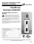
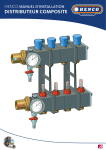
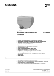
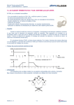
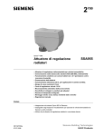
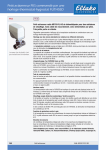
013R9489 Installation Guide — Manuel d'installation an M30x1.5 built-in valve insert: - thermostatic sensor RАЕ-К - H-piece, type RLV-KS Conçu pour les radiateurs avec arrivées par le sol et équipés d’un insert M30x1,5 : - tête thermostatique RАЕ-К - raccord en H, de type RLV-K 1.0 1. 1.0 1 2.0 2. 1 2 2 3 3 2.0 8 mm 8 mm Danfoss Heating Solutions DANFOSS HEATING 1 1 Installation Guide 3. Danfoss Thermostatic Sensors RAE-K Têtes thermostatiques RAE-K Danfoss Remove the protective cap from the valve insert by turning it anticlockwise. Retirez le capuchon de protection de l’insert : pour cela, tournez-le dans le sens contraire des aiguilles d’une montre. Ensure that the setting mark on the sensor is positioned at the top before mounting the sensor. Assurez-vous que le repère de réglage de la tête est situé sur le haut avant de monter la tête. Mount the thermostatic sensor on the valve and tighten it with a 32 mm spanner (max torque 15 Nm) Fixez la tête thermostatique sur l’insert et serrez-le au moyen d’une clé plate de 32 mm (avec un couple de 15 Nm maximum). 4. Adjusting Temperature Control Range Limitation de la plage de réglage de la température Setting the upper limit: e.g. at the III position. 1. Set the thermostatic sensor to the maximum temperature. 2. Press down the limiter tab to the right of the setting mark with a screw driver and turn the thermostatic sensor to position III, while pressing/holding down the limiter tab. 3. Release the tab. 8 I 12 II III IIII 16 20 24 I 28 °C Limitation maximale : par exemple, sur la position III. 1. Régler la tête en butée sur la température maximale. 2. A l’aide d’un tournevis plat, enfoncer la taquet situé dans la fente à droite de l’index . 3. Tourner jusqu’à la position III et relâchez le taquet. 2 Setting the lower limit: e.g. at the II position. 1. Set the thermostatic sensor on minimum temperature. 2. Press down the limiter tab to the left of the setting mark with a screw driver and turn the thermostatic sensor to position II while pressing/ holding down the limiter tab. 3. Release the tab. Limitation minimale de la température : par exemple, sur la position II. 1. Régler la tête en butée sur la position minimale. 2. A l’aide d’un tournevis plat , enfoncer le taquet situé dans la fente à gauche de l’index. 3. Tourner jusqu’à la position II et relâcher le taquet. 2 8 I 12 3 II III IIII 16 20 24 2 I 28 °C 3 VIFNJ183/ 013R9512