1
Manuel d’installation
PLAFONNIER HIGHLIGHT XL GREEN VIA
Consignes de sécurité, avertissements.
Avant de commencer à faire fonctionner votre luminaire LED, assurez-vous qu’il n’a pas été
endommagé pendant le transport.
Avant de commencer l’installation ou l’entretien, veuillez couper l’alimentation à partir du tableau
électrique.
Ne rétablissez jamais l’alimentation avant que tous les composants ne soient correctement installés.
Ce luminaire doit uniquement être installé par un professionnel qualifié.
Afin d’éviter les risques d’étouffement ne laissez pas les emballages à la portée des enfants ou des
animaux domestiques.
Ne pas enlever la plaque signalétique.
Toujours s’assurer que la tension d’entrée (indiquée sur l’étiquette du transformateur) correspond à
votre circuit d’alimentation.
Les réparations doivent être effectuées par des spécialistes.
Ne jamais réparer les pièces défectueuses soi-même.
Ne pas apporter de modifications électriques ou mécaniques sur le luminaire.
Ne pas exercer de pression sur le luminaire sous risque de déformer et d’endommager le déflecteur.
Le plafonnier peut être installé de diverses manières. Veuillez d’une part vous assurer de la qualité
des composants utilsés (visseries, chainette, filin métallique, etc...) d’autre part vérifier que
l‘ensemble des pièces utilisés sont correctement vissés et installés.
Respecter les plages de température et de tension de fonctionnement indiquées.
Raccorder le luminaire au secteur en veillant à bien respecter les couleurs des fils électriques
(Marron : PHASE, Bleu : NEUTRE, Jaune et vert : TERRE.).
GREEN VIA - 47, rue Maurice Flandin 69003 Lyon - Tél : +33 4 72 15 76 44 - Fax : +33 4 26 69 88 15 - [email protected]
www.green-via.fr - SAS au capital de 53 000€ - N° SIRET : 523 258 697 00011 - N° TVA Int : FR77523258697 - RCS LYON
Ø
∅6mm
Ø
∅6mm
Ø
∅6mm
26mm
26mm
Ø
∅6mm
Connecter
lesàveillant
câbles
veillant
àles
respecter
les
bonnes
couleurs
: :Marron
: Bleu
Phase,
Bleu
: Neutre,
Connecter
les
câbles
en
veillant
àles
respecter
les
bonnes
couleurs
: Marron
Phase,
: Neutre,
Jaune
etJaune
vert
: et
Te
Connecter
Connecter
les
câbles
Connecter
les
en
câbles
veillant
les câbles
en
respecter
en veillant
àenrespecter
bonnes
à respecter
couleurs
bonnes
les bonnes
couleurs
: Marron
couleurs
::Marron
Phase,
: Marron
:Bleu
Phase,
: Neutre,
: Phase,
Bleu
:Jaune
Neutre,
Bleu
:etNeutre,
Jaune
vert
: Terre
et
Jaune
vert
:etTerre
vert
Technical
Parameter
MANUEL D’INSTALLATION
PLAFONNIER
HIGHLIGHT
COMPACT
GREEN
VIA
, the
the
LED
Linear
warehouse
Light
is
d
current
constant
voltage
power
driver
Power
Frequency
Power
Frequency
Fixture
Material
Aluminum
Fixture
Material
Alloy
Alu
50
/
60Hz
50
/
60Hz
4.Please
4.Please
cut
4.Please
off
the
cut
cut
off
power
off
the
the
when
power
power
it
when
smokes
when
it
smokes
it
or
smokes
smells
or
smells
or
awfully
smells
awfully
since
awfully
the
since
since
accident
the
accident
of
accident
fire
or
of
electric
fire
of
fire
or
electric
or
shock
electric
Installation
Manual
Installation
Manual
1.To avoid
1.To
1.To
the
avoid
avoid
accident
thethe
accident
of
accident
damage
of damage
of, falling
damage
, falling
electric
, falling
, electric
shock
, electric
or
shock
fire.
shock
or
please
fire.
or fire.
please
doplease
not do
reform
do
notnot
reform
thereform
lamp
the
or
the
lamp
replace
lamp
orshock
replace
orshock
repla
, shopping center, andInput
otherVoltage
appplications.
high
racks
aside
AC100~24
may
incur.
may
may
Ask
incur.
incur.
the
Ask
qualified
Ask
the
the
qualified
personnel
qualified
personnel
for
maintenance.
for
maintenance.
maintenance.
Procédure
d’installation
CRI
CRI
Working
Temperature
Working
-30~+55℃
Temperature
/us
≥80
/ ≥80
the
accessories
the
the
accessories
accessories
and
confirm
and
and
confirm
with
confirm
us≥70
with
if personnel
you
with
need
us
if you
ifforyou
to
need
change
need
to change
to≥70
the
change
mounting
thethe
mounting
mounting
methods.
methods.
methods.
Step1
Etape
N°1
Step1
5.Please
5.Please
do
5.Please
not
do
dismantle
do
not
not
dismantle
dismantle
the
lamp
the
by
the
lamp
yourself
lamp
by
by
yourself
since
yourself
the
since
since
accident
the
the
accident
may
accident
incur.
may
may
incur.
incur.
Turn
off
the
switch
o
o
o leTurn
oswitch
o
o
o
o PLAFONNIER
o
HIGHLIGHT
COMPACT
Couper
courant
off theD’INSTALLATION
Power
Frequency
50 GR
/6
2.Please
2.Please
authorize
2.Please
authorize
theemballage
installation
the
the
installation
installation
to
qualified
to
qualified
too installation
installation
installation
personnel
personnel
personnel
and
obey
andand
to
obey
the
obey
instruction
to
the
to the
instruction
instruction
manual.
manual.
manua
Angle
Beam
Angle
Working
Humidity
Working
15%~90%RH
Humidity
15
30
x70
/ comporter
60MANUEL
x90
/qualified
120
30
x70
/ 60
x90
/Installation
120
Le Beam
contenu
de authorize
votre
doit
le luminaire
LED
ce
manuel
d’installation
ainsi
que le
kit
Installation
Manual
Manual
MANUEL
D’INSTALLATION
PLAFONNIER
HIGHLIGHT
COMPACT
GREEN
VIA
6.Please
6.Please
do
6.Please
not
do
touch
do
notnot
the
touch
touch
driver
the
the
when
driver
driver
the
when
when
lamp
the
works.
the
lamp
lamp
works.
works.
Installation
Manual
de unsuitable
fixation
(siunsuitable
commandé).
Any
Any
Any
unsuitable
installation
installation
installation
willIP
easily
will
will
cause
easily
easily
the
cause
cause
accident
the
the
accident
of
accident
falling
of, falling
electric
of falling
, electric
shock
, electric
and
shock
shock
fireand
etc.
and
fire
fire
etc.etc.
Installation
Manual
CRI
≥70 -/
IP
Rating
Rating
Storing
Temperature
Storing
-40~+65℃
Temperature
IP65
IP65
Technical
Parameter
MANUEL
D’INSTALLATION
PLAFONNIER
HIGHLIGHT
COMPACT
GREEN
VIA
OFF
7.If
the
7.If
external
7.If
the
the
external
flexible
external
flexible
cable
flexible
or
cable
cord
cable
or
of
cord
or
this
cord
luminaire
of
this
of
this
luminaire
luminaire
is
damaged
is
damaged
is
,
damaged
it
shall
,
it
be
,
shall
it
exclusively
shall
be
be
exclusively
exclusively
replaced
replaced
by
replaced
the
by
by
theth
OFF
3.Please
3.Please
cut
3.Please
off the
cutcut
off
power
off
thethe
before
power
power
before
installation
before
installation
installation
or any or
maintenance
any
orManual
any
maintenance
maintenance
of off
the
lamp.
of
the
ofthe
the
lamp.
lamp.
Step1
Etape
N°1
Step1
Turn
switch
Installation
Angle
30ox70o / 60
Couper
lethe
courant
Turn
offBeam
switch
Installation
Manual
Step1
Etape
N°1
Step1
manufacturer
manufacturer
manufacturer
or the
hiscut
service
oroff
his
or the
his
service
agent
service
or
agent
aInstallation
agent
similar
a
or
similar
qualified
aoffsimilar
qualified
person
qualified
person
in person
order
in
toorder
inthe
avoid
order
toof
a
avoid
tohazard.
avoid
a electric
hazard.
a hazard.
Turn
switch
en
suspension
Couper
le
courant
Turn
the
4.Please
4.Please
cut
4.Please
off
cut
off
power
the
when
power
power
itwhen
smokes
when
itoffor
smokes
itthe
or
smokes
smells
orswitch
smells
or
awfully
smells
awfully
since
awfully
the
since
since
accident
the
accident
accident
fire
or
of
fire
of
fire
or electric
orshock
electric
shock
shock
Input
Voltage
Lifespa
AC100~240V
/ 277V
MANUEL
D’INSTALLATION
PLAFONNIER
HIGHLIGHT
COMPACT
GREEN
VIA
IP Rating
IP6
Installation
Manual
Technical
Parameter
Technical
Parameter
Installation
Manual
Step1
N°1
Step1
mayEtape
incur.
may
may
Ask
incur.
incur.
the
Ask
qualified
Ask
the
the
qualified
personnel
qualified
personnel
personnel
for
maintenance.
for
for
maintenance.
maintenance.
TurnPower
offlethe
switch
Couper
courant
OFF OFF
Turn
off the switch
Step2 N°2
Step2
Frequency
Fixture Ma
50 / 60Hz
Etape
Application
Application
Application
MANUEL D’INSTALLATION
PLAFONNIER
HIGHLIGHT
COMPACT
GREEN VIA
OFF
OFF
5.Please
5.Please
do
5.Please
not do
dismantle
do
not
not
dismantle
dismantle
the
lamp
the
by
the
lamp
yourself
lamp
by
by
yourself
since
yourself
the
since
since
accident
the
the
accident
may
accident
incur.
may
may
incur.
incur.
1 Percer
un
trou
de
mm
deInstallation
diamètre
Installation
Manual
Manual
1 Drill φ6mm
holes
on 6
the
roof/wall
1 Drill
φ6mm
holes
on
the
roof/wall
Etape
Step1 N°1
Step1 Percer
CRI
Working
Temp
≥70
/ LED
≥80
offlethe
switch
Couper
courant
Turn
offsink
the
switch
A
A
la
surface
deTurn
fixation
(mur,
plafond)
puis
yexpansion
Technical
Parameter
2 Insert
φ6
mm
With
unique
With
With
unique
high
unique
purity
high
high
die-cast
purity
purity
die-cast
aluminum
die-cast
aluminum
aluminum
heay
heay
heay
,
high-power
sink
sink
,
high-power
,
high-power
single
LED
single
single
chip
,LED
high-effciency
chip
chip
, high-effciency
, high-effciency
constant
constant
const
2
Insert
φ6mm
expansion
6.Please
6.Please
do
6.Please
not do
touch
do
notnot
the
touch
touch
driver
thethe
when
driver
driver
the
when
when
lamp
theworks.
the
lamp
lamp
works.
works.
OFF
OFF
pipe
into
the
hole
and
fix
pipe
into
the
hole
and
fix
o
o
o
o
o
visser
fermement
la ,fixation
retenue.
Beam
Angle
Working
Hu
30
x70
/Light
60isx90
/ 120
Step2
Step2
the bracket
by
screw.
current
current
constant
current
constant
voltage
constant
voltage
power
voltage
driver
power
power
driver
driver
the
LED
,luminaire
the
,off
Linear
the
LED
LED
Linear
warehouse
Linear
warehouse
warehouse
Light
is
designed
is designed
for
warehouse
for for
warehouse
warehouse
with
with
with
bracket
byLight
M4
screw.
Step1
N°1
Step1
Etape
N°2
7.If Etape
the
7.If
external
7.If
thethe
external
flexible
external
flexible
cable
flexible
or
cable
cord
cable
or
of
cord
or
this
cord
of
this
of
this
luminaire
luminaire
is damaged
is damaged
isthe
,damaged
itM4shall
, designed
itbe
,shall
itexclusively
shall
be
be
exclusively
exclusively
replaced
replaced
by
replaced
the by
by
the
th
Turn
offle
the
switch
Couper
courant
Turn
the
switch
Outlet
Box
Step2
Step2
OFF
1
Percer
un
trou
de
6
mm
de
diamètre
OFF
Etape
N°2
1
Drill
φ6mm
holes
on
the
roof/wall
1
Drill
φ6mm
holes
on
the
roof/wall
A
high
racks
high
high
aside
racks
racks
,his
shopping
aside
aside
shopping
,his
shopping
center
,center
and
center
other
, or
and
,a
and
appplications.
other
other
appplications.
appplications.
IP
Rating
Storing Temp
IP65
manufacturer
manufacturer
manufacturer
or
service
or ,his
or
service
agent
service
or
agent
a
agent
similar
or
similar
qualified
a
similar
qualified
person
qualified
person
in person
orderintoorder
in
avoid
order
toaavoid
tohazard.
avoid
a hazard.
aφ62hazard.
mm
expansion
1 Percer
un
trou
de
mm
dethediamètre
Insert
φ6mm expansion
1 Drill φ6mm
holes
on 6the
roof/wall
2 Insérer les chevilles de 6 mm2 Insert
de diamètre
1 Drill
φ6mm
holes
on
roof/wall
Step2
Step2
pipe into the
hole
and
pipe
into
thefixhole and fix
Etape N°2 Préparer votre luminaire :
2 Insert φ6
expansion
2 mm
Insert
φ6trous
mm
expansion
OFF
dans
les
et y visser lesthe
supports
OFF
bracketthe
bybracket
M4 screw.
by M4 screw.
Ø
∅6mm
Ø
∅
pipe into the hole and fix
1 Percer
un
trou
de
mm
dethediamètre
1 Drill φ6mm
holes
on 6the
roof/wall
1 Drill
φ6mm
holes
on
roof/wall
Application
Application
Application
the bracketthe
bybracket
M4 screw.
by M4 screw.
Step2
Step2
2
Insert
φ6
mm
expansion
2
Insert
φ6mm expansion
Technical
Parameter
Etape N°2
Raccorder
le câble
d’alimentation au
pipe
into
the
hole
and
fix
pipe
into
the
hole and
fix
-purity
les
câbles
de
fixation
puis
passer
Technical
Technical
Technical
Parameter
Parameter
Parameter
2 chip
lesconstant
chevilles
de
6 mm
1dérouler
Percer
un
trou
de
mm
de
diamètre
Step3
1 Drill
φ6mm
holes
on 6the
roof/wall
Step3
With
unique
With
With
unique
high
unique
high
high
die-cast
purity
purity
die-cast
aluminum
die-cast
aluminum
aluminum
heay
sink
heay
heay
, high-power
sink
sink
, high-power
,les
high-power
single
LED
single
single
chip
LED
,LED
high-effciency
chip
, Insérer
high-effciency
, high-effciency
constant
const
1
Drill
φ6mm
holes
on
the
roof/wall
the
bracket
bybracket
M4 screw.
connecteur
rapide
the
by
M4
screw.
26mm
Ø
∅6mm
Ø
∅6mm
26mm
26mm
26mm
pipe into the hole and fix
26mm
26mm
26mm
26mm
26mm
26mm
26mm
26mm
Ø
∅6mm
6mm
∅
6mm
∅6mm
Ø
∅
Ø
∅6mm
Ø
∅6mm
Installation
Manual
Installation
Manual
Ø
∅6mm
LL(BR)
LL(BR)
(B)
N
DriverDriver
N
(BR)
(BR)
Technical
Technical
Technical
Parameter
Parameter
N(K)
(B)
N(B)
(B)
G (K)Parameter
G
N
N
G (K)
Connecter les câbles en veillant à respecter les bonnes couleurs : Marron : Pha
Etape
STEP
Open the sling and
STEP 1: Open
the 2:
sling
and
STEP
Straighten
STEP
STEP
2:
Straighten
3: Put the
and
other
side
STEP
ofdans
the3:
sling
Put
theetother
side
les
trous
y visser
2Insert
Insérer
les
de
6 mm
de diamètre
Step21:N°3
Step2
dans les trous
de montage
àand
cet
effet,
2
φ6
expansion
2 mm
Insert
φ6chevilles
mm expansion
L (BR) réservés
L (BR)
L (BR)
Ladjust
(BR)
Etape
N°2
lock,
put
the constant
sling
through
lock, put
the ,adjust
sling
through
these
two
slings
to
adjust
through
these
two
the
slings
mounting
to
hook,
through
the
and
mounting
hook
pipe
into
the
hole
and
fix
current
current
constant
current
voltage
constant
voltage
power
voltage
driver
power
power
driver
driver
the
LED
,
the
,
Linear
the
LED
LED
Linear
warehouse
Linear
warehouse
warehouse
Light
is
Light
designed
Light
is
designed
is
designed
for
warehouse
for
for
warehouse
warehouse
with
with
with
pipe les
into the
holeet
andyfix
dans
trous
visser les supports
Aondethediamètre
1 Voltage
Percer
un
trou
de
mm
Input
Voltage
Input
Input
Voltage
Lifespan
Lifespan
≥50000Hrs
≥50000Hrs
AC100~240V
AC100~240V
AC100~240V
/roof/wall
277V
/ 277V
277V
1 Drill
φ6mm
holes
on 6the
roof/wall
1 Drill
φ6mm
holes
by
M4
screw.
the
bracket
by
screw.
the
mounting
holes
each
the
mounting
holes
on
each
ensure
the
fixture
is/ in
ensure
tighten
the
fixture
theM4
lock
isLifespan
intoa
tighten
fixture
the
is≥50000Hrs
lock toleensure
2athe bracket
allen driver
Insérer
les
chevilles
de
6ensure
mm de the
diamètre
allen
driver
Cléon
allen
Raccorder
câble dt
G
(K)
G (K)
, shopping
, shopping
, shopping
center,center
and
center
other
,Gand
, and
appplications.
other
other
appplications.
appplications.
high racks
high
high
aside
racks
racks
aside
aside
2 Insert φ6
expansion
(K)
G (K)
2 mm
Insert
φ6mm expansion
side
of
the
fixture.
side
of
the
fixture.
horizontal
plan.
horizontal
mounted
plan.
at
desired
height.
mounted
Connect
at
the
desired
height.
dans
les
trous
et
y
visser
les
supports
STEP
1:
Open
the
sling
and
STE
Step3
Step3
into Fixture
the
hole
and
fixhole
pipe
into
the
and
fix Material
r
Power Power
Frequency
Power
Frequency
Frequency
Fixture
Material
Fixture
Material
Aluminum
Aluminum
Aluminum
Alloyconnecteur
Alloy
Alloy
50N°3
/ fixation
60Hz
50 50
/ 60Hz
/ 60Hz pipeafin
Raccorder
le câble
d’alimentation
au
Etape
- de
tendre
les
câbles
fermement
qu’ils
IP68 Step3
waterproof
connector
wiring
diagram
Schéma
raccordement
IP68 waterproof
connector
wiringde
diagram
the bracket
by
M4(BR)
screw.
L
L
power
cable,
make
sure
the
power
wiring
cable,
is
make
sure
th
the
bracket
by
M4
screw.
2
Insérer
les
chevilles
de
6
mm
de
diamètre
lock,
put
the
sling
through
adju
Step3
L
(BR)
N
(B)
N
(B)
connecteur
rapide
N
(B)
N
(B)
Etape N°3du connecteur IP68
aient
pour
installation
Lles
(BR)
CRI CRI
CRI la même longueur
Working
Working
Temperature
Working
Temperature
-30~+55℃
-30~+55℃
-30~+55℃
≥70L/(BR)
≥80
≥70≥70
≥80
/ ≥80
dans
les
trous
et
ywrap
visser
supports
correct,
then
the
naked
correct,
then
cords
wrap the nake
L/une
(BR)
Lcable
(BR)
the
mounting
holes
on each
ens
Raccorder
leTemperature
câble
d’alimentation
au
allen driver
allen
driver
Clé allen
Step3 Step3 parfaitement horizontale,
MANUEL
D’INSTALLATION
PLAFONNIER
HIGHLIGHT
COMPACT
G
G
(K)
with
tapes,
switch
with
oninsulating
the light tapes, switc
Ginsulating
(K) connecteur
sidede
of6the
fixture.
hor
rapide
Etape N°3
les
chevilles
mm
de
diamètre
o
o o oo o oo o o oo o 2 o Insérer
o
allen
driver
allen
driver
Clé Angle
allen
Beam
Angle
Beam
Beam
Angle
Working
Working
Humidity
Working
Humidity
Humidity
15%~90%RH
15%~90%RH
15%~90%RH
30 x70
30
/ 60
30
x70
x90
x70
/
60
/
/
120
60
x90
x90
/
120
/
120
L (BR)
L
(BR)
Technical
Technical
Technical
Parameter
Parameter
Parameter
L
(BR)
L
(BR)
G (K)
G
(K)
to
check
the
fixture
is working
to check
well.
G (K)
G (K)
Raccorder
leycâble
auif the fixture is wo
dans
les
trousif et
visserd’alimentation
les
supports
IP68 waterproof
connector
wiring diagram
Schéma
de
raccordement
IP68 waterproof
connector
wiring
diagram
N (B) connecteur
N
N (B)
Installation
seule
Step3 N°4
Step4
Single
Step3
Step4
Single
Etape
rapide
N°3
allen
driver
IP68
waterproof
connector
wiring diagram
du connecteur
IP
Rating
IP Rating
IP
Rating
StoringStoring
Temperature
Storing
Temperature
Temperature
-40~+65℃
-40~+65℃
-40~+65℃
IP65
IP65
IP65 IP68
allen
driverconnector
Schéma
de
raccordement
IP68
waterproof
wiring diagram
Clé
allen
L
(BR)
L
(BR)
G (K) N
G (K) N
(B)
N
(B)
L
(BR)
L
(BR)
G
(K) N
G (K)
(B)
(B)
L
(BR)
L
(BR)
Input Voltage
Input
Input
Voltage
Voltage
Lifespan
Lifespan
≥50000Hrs
≥50000Hrs
≥50000Hrs
AC100~240V
AC100~240V
/ 277V
/ 277V
/the
277V
Step1
Etape
N°1
Step1
Raccorder
leLifespan
câble
au
du
connecteur
IP68AC100~240V
STEP
1: Open
sling and
STEP
2: d’alimentation
Straighten
and
STEP 3: P
Turn
offlethe
switch
Couper
courant
G
(K)
Turn
off
the
switch
L (BR)
G (K)
L (BR)
Step3
Step3
IP68
waterproof
connector
wiring
diagram
Schéma
de
raccordement
IP68
waterproof
connector
wiring
diagram
connecteur
rapide
N
(B)
Etape N°3
allen driver
N
(B) through th
allen
driver
lock,
put
the
sling
through
adjust
these
two
slings
to
Clé
allen
N
(B)
N
(B)
N
(B)
N
(B)
Couper
G50
(K) / L
GAluminum
(K) L (BR)
Power Power
Frequency
Power
Frequency
Frequency
FixtureFixture
Material
Fixture
Material
Material
Alloy Alloy
Alloy
60Hz
50 50
/L60Hz
/ 60Hz
G (K)
GAluminum
(K) Aluminum
(BR)
L (BR)
(BR)
N (B) le
du connecteur
IP68
Ncourant
(B) Step4
seule
Single
the
mounting
holes
on each Installation
ensure
the fixture is in a
tighten the
Step4
Single
Etape
N°4
Technical
Technical
Technical
Parameter
Parameter
Parameter
Connect
in
series
Connect
in
series
Installation
en
série
MANUEL
D’INSTALLATION
PLAFONNIER
HIGHLIGHT
COMPACT
GREENOFF
Lhorizontal
(BR)
GVIA
(K)
IP68 Step4
waterproof
connector
wiring
L (BR)
L≥80
(BR)
Schéma
de
G (K)mounted a
IP68
waterproof
wiring
diagram
L (BR) Working
OFF
Step4
side
of
the
fixture.
Single
allen
driver
(BR)
Lraccordement
CRI
CRI
CRI
Working
Temperature
Working
Temperature
Temperature
-30~+55℃
-30~+55℃
≥70
≥80
≥70
≥70
/(B)
/seule
≥80
allen
driverconnector
N/Installation
(B)
Nplan.
(B) -30~+55℃
L (BR) diagram
Clé
allen
Etape
N°4
NSingle
Installation
Manual
Installation
Manual
G
(K)
G
(K) N (B)
G
(K)
G
(K)
G
(K)
G
(K)
du
connecteur
IP68
L
(BR)
G (K)
L (BR)
G (K)
power cab
o
o o oo o oo o o oo o
o o
GBeam
(K) Angle
L (BR)15%~90%RH
GAngle
(K)
L
(BR)
Installation
seule
Step4
Single
Step4
Beam
Angle
Beam
Working
Working
Humidity
Working
Humidity
Humidity
15%~90%RH
15%~90%RH
30
x70
30
/
60
30
x70
x90
x70
/
60
/
/
120
60
x90
x90
/
120
/
120
Single
IP68 N°4
waterproof
connector
wiring
diagram
Schéma
de
raccordement
IP68
waterproof
connector
wiring
diagram
Etape
(B)
N
(B)
N
(B)
N
(B)
NTurn
(B)
A
AA
N
(B)
N (B) N (B)
N (B) N (B)N (B) N (B) correct, th
Step1 N
Step1
LEtape
(BR)
offlethe
switch
LN°1
(BR)
Couper
courant
Turn
off the switch
Connect
in
series
du connecteur
IP68
Connect
in series
Installation
en
série
with insula
N(K)
(B)
N (B) Step2 IP65
L (BR
G (K)
L (BR) -40~+65℃
G
L-40~+65℃
(BR) L (BR)
IP Rating
IP
Rating
IP Rating
StoringStoring
Temperature
Storing
Temperature
Temperature
-40~+65℃
IP65
IP65
Step2
(BR)
L en
L (BR)
Installation
seule
Step4
Single
Etape N°2
Step4
Connect
in
series
Single
Connect
in series
Installation
série
Etape
N°4
to
check
i
N
L
(BR)
N
(B)
G(B)
(K)
L
(BR)
G
(K)
G
(K)
Passer
les
câbles
de
fixation
dans
les
crochets
de
G
(K)
Outlet Box OutletOutlet
Box Box
(BR)
LL
(BR) L
(BR)
L
(BR)
1 Percer
un
trou
de
mm
dethediamètre
1 Drill φ6mm
holes
on 6the
roof/wall
1 Drill
φ6mm
holes
on
roof/wall OFF
N
(B)
OFF
N
(B)
L
L L
G (K) fixation,
L (BR)
G (K)
L
Lφ6
(BR)
ajuster
la longueur
etSingle
sérrer
fermement.
(B)
(B)series
Nen
N (B
(B)series
N
Connect
in
expansion
Connect
in
Installation
série
Insert
mm N
expansion
L
Installation
seule
L
Step4 N°4
L (BR) L (BR)2 Insert φ62 mm
Step4
Single
(K)
(K)
Etape
NG(B)
NG(B)
26mm
26mm
hole
and
pipe
into
thefixhole and fix
N (B) N (B) pipe into the
the bracketthe
bybracket
M4 screw.
N
Nseries
N
L (BR) L (BR)by M4 screw.
G (K)
Connect en
in
Connect
Installation
série inNseries
L
(BR)
Step2 N°2
(K)
Step2
L
(BR)
(K)
(B)
N
NG(B)
Etape
(B)
N(BR) L
N (B)L L
NG(B)
(B)
N(BR)
L
L
L
un
trou
de
mm
de
diamètre
N(K)(B) N (B) 1 Percer
G (K)
1 Drill φ6mm
holes
on 6the
roof/wall
G
1 Drill
φ6mm
holes
on
the
roof/wall
LL
2 Insérer les chevilles de 6 m
LL
ASTEPA1:STEP
A
Connect en
in
series
LDriver
Connect
series
Installation
série in
2 Insert φ6
LDriver
2 mm
Insert
φ6mm expansion
Lexpansion
(BR)
Gside
(K)
L
(BR)
(K)
(B)
N
dans
les
etsling
y visser
Open
STEP
1:the
Open
1:N
sling
Open
and
the
sling
andandSTEP 2:STEP
Straighten
STEP
2:
Straighten
2:
Straighten
and
and
and
STEP
3:
STEP
Put
STEP
the
3:
Put
other
3:
Put
the
side
the
other
of
other
the
side
sling
of trous
the
ofGthe
sling
L the
L sling
(B)
(B)
N
(B)
N
pipe
into
the
hole
and
fix
(BR)
L
pipe
into
the
hole
and
fix
(BR)
L
en suspension
Hanging
Installation
N 2 2 Installation
Installation N
N 2 Hanging
Step5 Step5
N
N
N
Driver
the
bracket
by
M4
screw.
Driver
the
bracket
by
M4
screw.
G
(K)
Installation
au
plafond
Etape
GInstallation
(K)
lock, putN°5
lock,
the
lock,
put
put
through
the
sling
sling
through
through
adjust
these
adjust
adjust
two
these
slings
these
two
to
two
slings
slings
to
through
to
through
the
through
mounting
the
the
mounting
hook,
mounting
adjust
hook,
hook,
and
adjust
adjust
and
and
1the
L
Raccorder
le
luminaire
au
secteur
en
veillant
à
L
L
1 sling
Ceiling
L
1N
Ceiling Installation
N
N
Ntheis
Outlet Box OutletOutlet
Box Box
N
Nfixture
Lholes
L on
the mounting
thethe
mounting
holes
mounting
on
each
holes
on
each
each
ensure
the
ensure
ensure
fixture
the
fixture
in
a
is
in
is
a
in
tighten
a
the
tighten
tighten
lock
the
to
the
ensure
lock
lock
to
the
ensure
to
ensure
fixture
the
is
the
fixture
fixture
is
is d
Raccorder
le
câble
(B)
N
(B)
N
(B)
N
(B)
N
bien respecter Driver
les
couleurs
des fils.
Driver
2 Insérer
les chevilles de 6 mm de diamètre
Step3 horizontal
Step3 horizontal
side of the
sideside
fixture.
of the
of the
fixture.
plan.
horizontal
plan.
plan.
mounted
mounted
at
mounted
desired
at
desired
height.
at
desired
Connect
height.
height.
Connect
the
Connect
the
the
connecteur
Nfixture.N Etape
N°3
L
L
N
L
N
N L (BR)
N L
dansL
les
trous et
yHanging
visser les
supports
(BR)
Installation
enthe
suspension
2 sure
Installation
L
2 sure
Hanging
Installation
L Step5 Step5
power cable,
power
power
make
cable,
cable,
make
make
the
wiring
sure
is
the
wiring
wiring
is is
2
Installation
au
plafond
Etape Driver
N°51 Ceiling
Driver
1 1Installation
en
suspension
Hanging
Installation
Ceiling
Installation
2 Hanging
Installation
correct,
correct,
then
correct,
wrap
then
the
then
wrap
naked
wrap
thecable
the
naked
naked
cords
cable
cords
cords
Step5 Step5
2 2 Installation
NInstallation
N au plafond
Raccorder
le
câble
d’alimentation
au cable
allen driver
L
allen
driver
L N
Clé N
allen
L
Etape N°51 Ceiling
N
L
N
1 1Installation
G
(K)
(K)with
Ceiling
Installation
Step3
Step3
L
L
with G
insulating
with
insulating
tapes,
insulating
switch
tapes,
tapes,
on
switch
the
switch
light
on on
thethe
lightlight
connecteur
rapide
Etape
N°3
en suspension
2 Installation
Hanging
Installation
Installation
L (BR)
L (BR) L (BR)
Driver
L (BR)2 Hanging
Step5 Step5
2
check
toif check
the
to check
fixture
if the
if is
the
fixture
working
fixture
is working
well.
is working
well.
well.
IP68Driver
waterproof
connector
wiring diagram
Schéma
de
raccordement
IP68 waterproof
wiringto
diagram
Installation
au plafond
Etape
1Open
N
N sling
N
(B)3:STEP
STEP 1:N°5
STEP
Open
STEP
1:the
1:1sling
Open
the
and
the
sling
and
andSTEP
2:STEP
Straighten
STEP
2: Straighten
2:connector
Straighten
and
STEP
Put
STEP
the
3: Put
other
3: Put
the
side
the
other
of
other
the
sideside
sling
of the
of the
sling
sling
N andand
1 Ceiling
Installation
N
(B)
N
N
Ceiling
Installation
N
allen driver
allen
driver du connecteur IP68
Clé allen
G (K)
Ghook,
(K) hook,
Marron
: PHASE,
Bleu
: NEUTRE,
Jaune
et
vert
: suspension
TERRE.
G2(K)Installation
Gadjust
(K) adjust
lock,
put
lock,
the
lock,
sling
put
put
the
through
the
sling
sling
through
through
adjust
these
adjust
adjust
two
these
slings
these
two
to
two
slings
slings
to
through
to
through
the
through
mounting
the
the
mounting
hook,
mounting
adjust
and
and
and
en
Hanging
Installation
2
Hanging
Installation
Step5
2
Step5
Step6
Step6
Remettre
leconnector
courant
Installation
au
plafond
N°5
1 1Installation
Etape
N°6
Turn
on
the
switch
IP68
waterproof
connector
wiring
diagram
Turn
on
the
switch
Schéma
de
raccordement
waterproof
wiring
diagram
the mounting
thethe
mounting
holes
mounting
on
holes
each
holes
onIP68
on
each
each
ensure
the
ensure
ensure
fixture
the
is
the
fixture
in fixture
a is inisaintighten
a
the
tighten
tighten
lockthe
to the
ensure
locklock
to the
ensure
to ensure
fixture
theis
the
fixture
fixture
is is
1
Ceiling
Ceiling
Installation
26mm
26mm
Ø
∅6mm
Ø
∅6mm
N (B) N (B)
N (B) N (B)
IP68 horizontal
side of the
sideside
fixture.
of the
of the
fixture.
fixture. du connecteur
horizontal
plan.
horizontal
plan.
plan.2 Hanging
mounted
mounted
atmounted
desired
at desired
height.
at desired
Connect
height.
height.
Connect
the
Connect
thethe
en
suspension
2 Installation
Hanging
Installation
Installation
2
Installation
seule
Step4
Single Single
Step4
Etape
N°4
Installation
au
plafond
1 1Installation
power
cable,
power
power
make
cable,
cable,
sure
make
make
the
sure
wiring
sure
the
is
the
wiring
wiring
is
is
1 Ceiling
Ceiling Installation
L (BR) L (BR)
ON ON
correct,
correct,
then
correct,
wrap
then
the
then
wrap
naked
wrap
the
cable
the
naked
naked
cords
cable
cable
cords
cords
Step6
Step6
G
(K)
Remettre
le
courant
G (K) Installation
seule
Step4 N°4
Single
Step4 Etape N°6
Turn on the
switch
Single
Turn
on the switch
Etape
L
(BR)
with
insulating
with
with
insulating
tapes,
insulating
switch
tapes,
tapes,
on
switch
the
switch
light
on
on
the
the
light
light
Step6
L
(BR)
Step6
Remettre
le courant
Etape N°6 Remettre le courant
Turn
on the
switch
Turn
on N
the(B)
switch
G (K)
L (BR)
G (K)
Lwell.
(BR)
N (B)
to check
to
if
check
the
to
check
fixture
if
the
if
is
the
fixture
working
fixture
is
working
well.
is
working
well.
(B)
Connect en
in series
Connect
Installation
série in series ON N (B) N
Step6
Remettre
ONL (BR) L (B
NTurn
(B)le courant
Etape Step6
N°6
N (B)
Attention
on
the
switch
(BR)
Turn
onLthe
switch
(BR)
L
Connect
in series
Connect
in
series
Installation
en
sérieON
Caution:
Plese
that
DOthat
NOT
use
this product
in the
places/application
Caution:
Plese
note
NOT
in the
following
places/application
G (K) product
L (BR) L (BR)
G (K)
ON
G (K)following
G (K)
Ne
pas utiliser
cenote
produit
dans
les DO
environnements
L (BR)useLthis
(BR) ou avec les applications suivantes :
1.The
place
has
a
large
quantity
of
lampblack
and
smoke,such
as:kitchen
and
Food
processing
factory
etc.
1.The
place
quantity
of
lampblack
and
smoke,such
as:kitchen
and
Food
processing
factory
G
(K) a large
Step6
G (K) l’industrie
Step6
Remettre
le
courant
Etape
N°6
- les
environnements
tels que
leshas
cuisines,
alimentaire,
etc.
dans
le
cas
de
forte
émanation
de
fumées
noires,
N (B) etc.N (
(B)switch
Turn on the
switch
N (B) substance,such
Turn
onN
the
ON
2.The place
al’industrie
large
of
chemical
as:chemical
plant
stockyard
etc.
ON
2.The
place
has quantity
a large
of chemical
substance,such
as:chemical
plant
and stockyard
etc.
N (B)
(B) quantity
Nchimique,
N (B)and
N (B)
- les environnements
telshas
que
dans
le corrosive
cas de corrosive
forte émanation
de
subtances
corrosives,
3.The
place
has
poor
temperature
conditions,large-scale
temperature
variation,which
would
easily
lead
to
Attention
3.The
place
has
poor
temperature
conditions,large-scale
temperature
variation,which
would
easily
lead
to
Step6
- les
environnements
des
écartsCaution:
de
température
au
delà
des
plages
d’utilisation
indiquées
dans
Step6
Remettre
le
courant
Etape
N°6 brokensubissant
Caution:
Plese
note
DO
NOT
use
this
product
inisavec
the
following
places/application
Turn
on
the
switch
Plese
note
that
DO
NOT
use
this
product
inisthe
following
places/application
Turn
onthat
the
switch
operating
temperature
between
-15
and
45
degrees.
and
damage
the
product,the
applicable
operating
temperature
between
-15
and
45
degrees.
broken
and
damage
the
product,the
applicable
Ne
pas
utiliser
ce
produit
dans
les
environnements
ou
les
applications
suivantes
:
Attention
ON
ONdu luminaire,
les
caractérisitiques
techniques
(-20/+45°C).
S’assurer
que
la
visserie
utilisée
puisse
supporter
le
1.The
place
has
aapplications
large
ofpoids
lampblack
and
Food
L and smoke,such
place
has
a large
quantity
of lampblack
an
Caution:
Plese
that
DOthat
NOT
use
thisuse
product
in1.The
the
following
places/application
L and smoke,such
Caution:
Plese
note
NOT
this
product
in the
following
places/application
Las:kitchen
Lquantity
les
environnements
tels
que
les
cuisines,
l’industrie
cas deas:kitchen
forte
émana
Ne
pas utiliser
cenote
produit
dans
les- DO
environnements
ou
avec
les
suivantes
L
L
L:alimentaire, etc.L dans le
L
L
L
L
2.The
place
has
a
large
quantity
of
chemical
corrosive
substance,such
as:chemical
2.The
place
has
a
large
quantity
of
chemical
corrosive
substance,such
as:c
1.The
place
has
a
large
quantity
of
lampblack
and
smoke,such
as:kitchen
and
Food
processing
factory
etc.
1.The
place
has
a
large
quantity
of
lampblack
and
smoke,such
as:kitchen
and
Food
processing
factory
etc.
Visser
fermerment
toutes
les
fixations
les environnements
telsDriver
que l’industrie
chimique,
dans
cas de forte
de subtances c
-Attention
les environnements
tels que
les -cuisines,
l’industrie
alimentaire,
etc.Driver
dans
leDriver
cas de
forteleémanation
de émanation
fumées noires,
Driver
ON
ON
Caution:
Plese
thathas
DO
NOT
use
this
product
inof
the
following
places/application
3.The
place
has
poor
temperature
conditions,large-scale
temperature
variation,wh
Caution:
Plese
this
product
in the
following
places/application
3.The
place
has
temperature
temperature
varia
2.The
place
athat
large
quantity
of
chemical
corrosive
substance,such
plant
stockyard
etc. indiqué
2.The
place
has
aNOT
large
quantity
chemical
corrosive
substance,such
as:chemical
plant
stockyard
etc.
N use
N
N
utiliser
cenote
produit
dans
les
environnements
ou
avec
les
applications
suivantes
: conditions,large-scale
Npoor
N
- DO
les
environnements
subissant
des
écarts
de
delà
plages
d’utilisation
N and
N Ntempérature
-Ne
lespas
environnements
telsnote
que
l’industrie
chimique,
dans
leN
cas
de
forte
émanation
de as:chemical
subtances
corrosives,
Nau
N and
Ndes
1.The
a
large
quantity
of
lampblack
and
smoke,such
as:kitchen
and
Food
processing
factory
etc.
operating
temperature
is
between
broken
and
damage
the
product,the
applicable
1.The
a
large
quantity
of
lampblack
and
smoke,such
as:kitchen
and
Food
processing
factory
etc.
operating
temperature
broken
and
damage
the
product,the
applicable
3.The
place
has
poor
temperature
conditions,large-scale
temperature
variation,which
would
easily
lead
to
3.The
place
has
poor
temperature
conditions,large-scale
temperature
variation,which
would
easily
lead
tois b
- les
les environnements
environnements subissant
tels que les
cuisines,
l’industrie
alimentaire,
etc.
le cas
de forte indiquées
émanationdans
de fumées noires,
les
caractérisitiques
techniques
-Attention
des
écarts
de
température
au delà(-20/+45°C).
desdans
plages
d’utilisation
2.The
place
has
a
large
quantity
of
chemical
corrosive
substance,such
as:chemical
plant
and
stockyard
etc.
2.The
place
has
a
large
quantity
of
chemical
corrosive
substance,such
as:chemical
plant
and
stockyard
etc.
operating
temperature
is
between
-15
and
45
degrees.
broken
and
damage
the
product,the
applicable
operating
temperature
is
between
-15
and
45
degrees.
broken
and
damage
the
product,the
applicable
Caution:
Plese
note
that
DO
NOT
use
this
product
in
the
following
places/application
Caution:
Plese
note
that
DO
NOT
use
this
product
in
the
following
places/application
- lescaractérisitiques
environnements
tels dans
que l’industrie
chimique, dans
le cas
forte émanation
de subtances
corrosives,
Ne
pas
utiliser ce produit
les
environnements
ou avec
les de
applications
suivantes
:
les
techniques
(-20/+45°C).
Step5 Step5
Etape N°5
Procédure d’installation
MANUEL D’INSTALLATION PLAFONNIER HIGHLIGHT COMPACT GR
Installation
Manual
Installation
Manual
Le contenu de votre emballage doit comporter le luminaire LED ce manuel d’installation ainsi que le kit
de fixation (si commandé).
Step1 N°1
Etape
Step1
Turn offlethe
switch
Couper
courant
Turn
off the switch
Installation au plafond
Connecter
les
câbles
en
veillant
les
bonnes
couleurs
Bleu
Jaune
Connecter
Connecter
Connecter
lesles
câbles
les
les
câbles
câbles
en en
veillant
en
en
veillant
veillant
à respecter
àrespecter
respecter
respecter
lesles
bonnes
les
les
bonnes
bonnes
couleurs
couleurs
couleurs
: Marron
:Marron
: Marron
Marron
: Phase,
:Phase,
: Phase,
Phase,
Bleu
Bleu
Bleu
: Neutre,
:Neutre,
: Neutre,
Neutre,
Jaune
Jaune
Jaune
et ve
Connecter
câbles
veillant
ààà
respecter
bonnes
couleurs
: :Marron
: :Phase,
Bleu
: :Neutre,
Jaune
OFF OFF
MANUEL D’INSTALLATION PLAFONNIER HIGHLIGHT COMPACT GREEN VIA
Installation
Manual
Installation
Manual
MANUEL
PLAFONNIER
HIGHLIGHT
COMPACT
MANUEL D’INSTALLATION
D’INSTALLATION
PLAFONNIER
HIGHLIGHT
COMPACT GREEN
GREEN VIA
VIA
Installation
Manual
Installation
Manual
MANUEL
D’INSTALLATION
PLAFONNIER
HIGHLIGHT
COMPACT
GREEN
VIA
Step2
Step2
B
B
B
Installation
Manual
MANUEL D’INSTALLATION
PLAFONNIER
HIGHLIGHT
COMPACT
GREEN
VIA
Installation
Manual
Etape
N°2
Installation
Manual
Installation
Manual
Step1 N°1
Etape
Step1
offle
the
switch
courant
Turn
offPercer
switch
1(mur,
un
trou
de
mm
dethediamètre
Percer la surface Couper
deTurn
fixation
plafond)
puis
yroof/wall
1the
Drill
φ6mm
holes
on 6the
1 Drill
φ6mm
holes
on
roof/wall
2 Insert φ6
expansion
Step1 N°1
2 mm
Insert
φ6mm expansion
Etape
Step1
visser
fermement
la
fixation
retenue.
Turn
off
the
switch
Couper
leTurn
courant
off the switch
Step1 N°1
Etape
Step1
pipe into the
hole
and
Turn offlethe
switch
pipe
into
thefixhole and fix
Couper
courant
Turn
off the switch
Step1
Etape
N°1
Step1
Turn
off
the
switch
Step1
Etape
N°1
Couper
le
courant
Turn
off
the
switch
Step1
the bracketthe
bybracket
M4 screw.
eep
allation
re installation
it well.
and keep
anditkeep
well.it well.
Turn offlethe
switch
by M4 screw.
Couper
courant
Turn
off the switch
OFF OFF
OFF
OFF OFF
OFF
2 Insérer les chevilles de 6 m
OFF
OFF OFF
OFF
dans les trous et y visser
Step2 N°2
Step2
Etape
gtric
ire.
, electric
shock
pleaseshock
ordofire.
notor
please
reform
fire. please
do
thenot
lamp
do
reform
not
or replace
reform
the lamp
theor
lamp
replace
or replace
STEP 1: Mark the
STEP
location
1:
STEP
Mark
of 1:
the
the
Mark
location
the locat
of th
Percer
un
trou
de
mm
dethediamètre
1 Drill φ6mm
holes
on 6the
roof/wall
B 1 B
B
Step2 N°2
1 Drill
φ6mm
holes
on
roof/wall
Raccorder
le the
câble
d
Step2
Etape
opening
hole
on
opening
the
roof,
opening
hole
drill
on
the
hole
the
roof,
on
drill
roo
t
Step2
Step2
Step3 Step3
2 Insert φ6
expansion
ou
he
d to
need
mounting
change
to
change
the
methods.
mounting
the
mounting
methods.
methods.
Etape
N°2
2 mm
Insert
φ6mm expansion
Step2
Step2
connecteur
Etape
N°3
Installer
les
équerres
sur
le
luminaire
puis
fixer
Step2
1
Percer
un
trou
de
6
mm
de
diamètre
Step2
Etape
N°2
1
Drill
φ6mm
holes
on
the
roof/wall
1 Drill
φ6mm
holes
on
roof/wall
holes.
holes. holes.
pipe into the
hole
pipe
into
thefixholeLand
fix
Etape N°2
1 Percer
un
trou
de
mm
dethe
diamètre
Land
(BR)
L
(BR)
1 Drill φ6mm
holes
on 6the
roof/wall
1 Drill
φ6mm
holes
on
the
roof/wall
1
Percer
un
trou
de
6to
mm
de
diamètre
the bracket
bybracket
M4
screw.
2 Insert
φ6
expansion
the
byexpansion
M4 screw.
2 mm
Insert
φ6
mm
alified
rsonnel
nstallation
installation
andpersonnel
obeypersonnel
tol’ensemble
and
instruction
obey
and
to
obey
the
manual.
instruction
the
instruction
manual.
manual.
1
φ6mm
holes
on
roof/wall
au
plafond.
1
φ6mm
holes
on
roof/wall
1the
Percer
un
trou
de
mm
dethe
diamètre
1 Drill
Drill
φ6mm
holes
on 6the
the
roof/wall
1 Drill
Drill
φ6mm
holes
on
the
roof/wall
2 Insert φ6
expansion
2 mm
Insert
φ6mm expansion
26mm
26mm
26mm
26mm
Ø
∅6mm
Ø
∅6mm
Ø
∅6mm
Ø
∅6mm
Ø
∅6mm
Ø
∅6mm
Ø
∅6mm
Ø
∅6mm
Ø
∅6mm
Ø
∅6mm
Ø
∅6mm
26mm
26mm
26mm
26mm
26mm
26mm
26mm
26mm
pipe
into
the
hole
and
fixhole
pipe
into
the
and fix
2
Insert
φ6
mm
expansion
2
Insert
φ6
mm
expansion
into
hole
and
fixhole
2 pipe
Insert
φ6
mm
expansion
pipe
into
the
and
fix
2the
Insert
φ6
mm
expansion
the bracket
by
M4
screw.
G
(K)
the
bracket
by
M4and
screw.
G
(K)
, electric
shock
electric
and ,fire
electric
shock
etc. shock
and fire
and
etc.
fire etc.
e
use
alling
accident
the
accident
of falling
of ,falling
pipe
into
the
hole
and
fix
pipe
into
the
hole
fix
the bracket
by
M4
screw.
into the
hole
and
fixby
the
bracket
M4
screw.
pipe
into
the
hole
and
fix
2pipe
Insérer
les
chevilles
de
6
the
bracket
by
M4
screw.
the
bracket
by
M4
screw.
thediagram
bracket
by
M4 screw.
the
bracket
by M4 screw.
connector
wiring
Schéma
de
raccordement
IP68 waterproof
connector
wiring
diagram
ation
rance
anyor
maintenance
ofany
the maintenance
lamp. of the of
lamp.
the lamp.IP68 waterproof
allen driver
allen
driver
Clé allen
Outlet Box Outlet
Outlet Box
Box Outlet Box
Installation
Manual
Installation
Manual
Couper le courant
L
L
L (BR)
(BR)
L (BR)
(BR)
allen driver
allen
driver wiring diagram
N (B) N (B)
Clé
allen
IP68 waterproof
connector
Schéma
de
raccordement
IP68
waterproof
wiring
diagram
allen
driver
Gexclusively
(K)
allen
driver
G
(K)
Clé
allen
maged
minaire
this
damaged
is
damaged
, itisshall
be
exclusively
, allen
it
shall
, itconnector
be
shall
replaced
exclusively
be
by
the
replaced
N
(B)
(B) by the by
G (K)
allen
driver
G
(K) Nreplaced
shock
ectric
shockluminaire
shock
driver
Clé
allen
allen
allen
driver IP68
Clé allen
dudriver
connecteur
G (K)
(K)
G
L (BR) L (BR)
G
G (K)
(K)
IP68 waterproof
connector
wiring diagram
Schéma
de
raccordement
IP68 waterproof
connector
wiring
diagram
qualified
on
milar
in order
qualified
person
to
avoid
person
in
order
a
hazard.
in
to
order
avoid
to
a
avoid
hazard.
a
hazard.
IP68
waterproof
connector
wiring
diagram
N
(B)
G (K) N (B)
Schéma
de
raccordement
IP68
waterproof
connector
wiring
diagram
G (K)
N
(B)
IP68
connector
wiring
N (B)
Schéma
de
raccordement
IP68
waterproof
connector
wiring
du connecteur
IP68
IP68 waterproof
waterproof
connector
wiring diagram
diagram
Schéma
de
raccordement
IP68
waterproof
connector
wiring diagram
diagram
N (B) N
(B)
du connecteur
IP68
C
C
C
the
Connecter les câbles en veillant à respecter les bonnes couleurs : Marron : Phase, Ble
mm de diamètre
dans les
trousN
et(B)
y visser les supports
N
(B)
N
22 Insérer
les chevilles de 6 mm de diamètre
du connecteur IP68
Insérer les chevilles de 6 mm de diamètre
amp
rce
rmells
replace
replace
replace
STEP
1:
STEP
STEP
Mark
1:
1:
STEP
the
Mark
Mark
location
1:
the
the
Mark
location
location
of the
the
of
ofshock
the
theD’INSTALLATION
of the
STEP
2:
STEP
STEP
Ensure
2:
2:
STEP
Ensure
Ensure
they de
triangle
2:
Ensure
the
the
triangle
triangle
bracket
the
triangle
bracket
bracket
is installed
bracket
is
is installed
installed
in is installed
in
in
in
2
es
since
ororsmells
awfully
the
accident
awfully
sinceof
the
since
fire
accident
or
the
electric
accident
of
fire
shock
of
or
fire
electric
or location
electric
shock
chevilles
6
mm
de
diamètre
dansHIGHLIGHT
les
trous
et
visser
les
supports
MANUEL
PLAFONNIER
HIGHLIGHT
COMPACT
G
2 Insérer
Insérer
les
chevilles
de
6
mm
de
diamètre
MANUEL D’INSTALLATION
PLAFONNIER
GREEN
VIA
dans
les
trous
et
yCOMPACT
visser
les
supports
Raccorder
le
câble
d’alimentation
au
openingopening
opening
hole on
opening
hole
hole
the roof,
on
onhole
the
the
drill
roof,
on
roof,
the
the
drill
drill
roof,
the
thedrillInstallation
the
the
right
the
the
way,
right
right
lift
the
way,
way,
and
right
lift
hang
lift
way,
and
and
the
lift
hang
hang
fixture,
and
the
the
hang
fixture,
then
fixture,
the
tighten
fixture,
then
then
tighten
tighten
then
tighten
C
C
C
dans
les
trous
et
y
visser
les
supports
Installation
Manual
Manual
dans
les
trous
et
y
visser
les
supports
Step3
Step3
or
ntenance.
maintenance.
connecteur
rapide
Etape N°3
holes. holes.
holes. holes.
the screws.
the
the screws.
screws.
Connect
the
screws.
Connect
Connect
the power
Connect
the
thecable,
power
power
themake
cable,
cable,
power
make
make
cable,sure
sure
make sure
Raccorder
le
câble
d’alimentation
ausure
Installation
seule
Step4 N°4
Single
Step4
Single
L (BR) L (BR)
L
(BR)
L
(BR)
Etape
manual.
manual.
ction
.
manual.
Raccorder
le
câble
d’alimentation
au
the
wiring
the
the
is
wiring
wiring
correct,
the
is
is
wiring
correct,
correct,
then
is
wrap
correct,
then
then
the
wrap
wrap
naked
then
the
the
wrap
cable
naked
naked
the
cable
cable
naked
cable
Step3
Step3
cident
fourself
sincemay
the
since
accident
incur.
the accident
mayEtape
incur.
may
incur.
LTurn
(BR)
Raccorder
le
câble
d’alimentation
au
Lcourant
(BR)
connecteur
rapide
Step1
N°1
Step1
Etape
N°3
Step3
Raccorder
le
câble
d’alimentation
authe
Step3
offlethe
switch
Step1
Couper
Turn
off thecords
switch
Etape
N°1
Step1
connecteur
rapide
with
cords
cords
insulating
with
with
cords
insulating
insulating
with
tapes,
insulating
switch
tapes,
tapes,
on
switch
switch
tapes,
the
light
on
switch
on
the
to
light
on
light
the
to
to
light
to
Turn
off
the
switch
Etape
N°3
Couper
le
courant
Turn
off
the
switch
tc.
Step3 Step3
L (BR)
LLrapide
(BR)
G (K) L (BR)
LL(BR)
G (K)
allen driver
allen
driver
Clé allen
connecteur
Step3
Step3
N°3
(BR)
(BR)
connecteur
rapide
G (K) L (BR)
G (K)
Etape
N°3
G (K) L (BR)
G (K) well.
check ifcheck
check
the fixture
ififcheck
the
theis
fixture
fixture
ifworking
the is
is
fixture
working
working
well.
is working
well.
well.
peworks.
lampEtape
works.
L
L
L (BR)
(BR)
L (BR)
(BR)
OFF
G (K)
OFF
G (K)
Connect en
in series
Connect
series
Installation
sérieNin(B)
G
(K) N (B)
GOFF
(K)
L (BR) L (B
OFF
G
G
G (K)
(K)
G (K)
(K)
N
(B)
N
(B)
N (B) N (B)
N
N
N (B)
(B)
N (B) N (B
N (B)
(B)
N (B) N (B)
Step2IP68
Step2
N (B) N (B)
du
Etape
N°2
du connecteur
connecteur
IP68
STEP 1: Fix theSTEP
mounting
1:
STEP
Fixbrackets
the
1: Fix
mounting
the
at mounti
brac
Installation
seule
Step4 N°4
Single
Step4
Single
1
Percer
un
trou
de
mm
de
diamètre
1
Drill
φ6mm
holes
on
roof/wall
Etape
1 Drill φ6mm6the
holes
on
the
roof/wall
Step2 Step2
L
(BR)
L
(BR) Etape N°2
a
suitable
location
a
suitable
on
the
a
suitable
location
roof.
location
on
the
roof.
on
th
2 Insert φ6
expansion
2 mm
Insert
φ6mm expansion
B GB(K) B
Installation
seule
Step4
Single
Step4
Single
pipeon
into
the
hole
and
1
Percer
un
trou
de
6
mm
de
diamètre
pipe
into
thefixhole and fix
G (K)
L
(BR)
L
(BR)
he
eplaced
dd by
by the
theEtape
by the N°4
1
Drill
φ6mm
holes
on
the
roof/wall
1
Drill
φ6mm
holes
the
roof/wall
Installation
seule
Step4
Single Single
Step4
Etape
N°4
M4 screw.
Lby M4 screw.
LL(BR)
L2 Insert
seule
m
y sink
heay
sinkLED
ower
single
, Etape
high-power
, N°4
high-power
chip
single
, high-effciency
single
LEDLL(BR)
chip
LED
, high-effciency
chip
constant
, Installation
high-effciency
constant
constant the bracketthebybracket
L φ6
Step4
Single
N
L (B)
Step4
Single
N (B)expansion
expansion
Installation
seule
2 mm
Insert
φ6mm
Step4
Single
Step4
(BR)
Single
(BR)
Etape
N°4
L
L
G (K) Raccorder
L
(BR)
G
(K)
le
luminaire
au
secteur
en
veillant
à
L
(BR)
L
(BR)
N
(B)
L
(BR)
N
(B)
pipe
into
the
hole
and
fixhole and fix
pipe
into
the
L
(BR)
G (K)
L
(BR)
L
(BR)
G (K)
L (BR)
DriverDriver
N
(B)
house
eLinear
LEDLight
Linear
warehouse
is designed
warehouse
Light
for
isLight
warehouse
designed
is designed
for
with
warehouse
for
warehouse
Connect
in with
series
N
(B)M4 screw.
Connect
series
G
Installation
en
série inNwith
L
(BR)
bracket
by
M4
screw.
G
2 InsérerLles
L
(BR)
the
bracket
by
chevilles
de 6the
mm
de
diamètre
(BR)
G (K)
(K) bien
N
L
(BR)
G
(K)
respecter
les
couleurs
des
fils.
L
(BR)
G (K)
(K)
N
(B)
L
(BR)
G(B)
(K)
N
N
N
Nthe
Nplace
Outlet
Box
Outlet
Outlet Box
Box Outlet Box
(BR)
LN
STEP
STEP
STEP
Fix
1:
1:
STEP
Fix
mounting
Fix the
the
1: Fix
mounting
mounting
brackets
the mounting
brackets
brackets
at brackets
at
at
at STEP 2:
STEP
STEP
Lift
the
2:
2:
STEP
Lift
fixture
Lifttrous
the
the
2: to
Lift
fixture
fixture
to
to
fixture
the
the
place
toN
place
(B) 1:
(BR)
LN
(B) the
(B)
N
(B)
dans
les
etthe
ythe
visser
les place
supports
N
(B)
N
(B)
N
(B)
N
(B)
Connect
in
series
G (K)
ppplications.
ther appplications.
Connect
in
series
G
(K)
Installation
en
série
a (B)
suitable
aaN
suitable
suitable
location
a suitable
location
location
on theInstallation
location
roof.
on
on Connect
the
the roof.
on
roof.
the
roof.
of
of the
the mounting
mounting
of
brackets.
the mounting
brackets.
N
(B)
LL(BR)
LLbrackets.
(BR) brackets. G (K)
G (K)
in series
(B)
Connect
en
série in series of the mounting
(B)
LLN(BR)
(BR)
LLN(BR)
G (K)
(BR) 2
G (K)
Insérer
les chevilles
de 6 m
Connect
in
series
Connect
in
series
Installation
en
série
(BR)
Connect
in
series
(B)
N
(BR)
Connect
in
series
L
(BR)
(B)
N
Installation
en
série
(B)
N
Raccorder
le
câble
d’alimentation
au
G
(K)
L
(BR)
(B)
N
G
ant
ciency
constant
constant
constant
G (K)
G
(K)
L (BR) L (BR)
G (K)
G (K)
(K)et y visser
L
(BR)
dans
les
trous
G (K)
Step3 L
(BR)
L
Step3
G(BR)
(K)
(BR)
L
connecteur
rapide
Etape N°3 Step5
enL (BR)
suspension
2 Installation
Hanging
Installation
G
Hanging
G
(K)
G (K)
(K)
Step5
(B) triangle
N
Lof
(BR)
(BR)
GSTEP
(K)
se
se
rehouse
with
with
with
(B)
N
amp
rce
r replace
replace
or replace
N
(B) 1:
N
1:
STEP
STEP
Mark
1:
STEP
the
Mark
Mark
location
1:the
the
Mark
location
location
of the
the location
of the
the
the L (BR)auSTEP
2:
STEP
STEP
Ensure
2:
2:
STEP
Ensure
Ensure
the
2: 2
Ensure
the
the(B)
triangle
triangle
bracket
the 2L
triangle
bracket
bracket
is installed
bracket
is
isInstallation
installed
installed
in is installed
in
in
in
Installation
plafond
1of
(B)
N
(B)
N
(B)
N
(B) Etape N°51 Ceiling
N
Installation
1
Ceiling
Installation
(B)
N
(B)
N
(B)
N
opening
opening
hole
on
opening
hole
hole
the roof,
on
onhole
the
the
drill
roof,
on
roof,
the
the
drill
drill
roof,
the
thedrill the
the rightthe
the
way,
right
right
lift
the
way,
way,
and
right
lift
hang
liftway,
and
and
the
lift
hang
hang
fixture,
andthe
the
hang
fixture,
then
fixture,
the
tighten
fixture,
then
then tighten
tighten
then
tighten
(B)
N
(B)
N
(B)
Nopening
(B)
N
(B) driver
N
Raccorder
le
câble
d
allen
allen
driver
Clé allen
G (K)L Jaune
Gmake
(K)
Marron
PHASE,
BleuStep3
: NEUTRE,
vert
TERRE.
G (K) L Let the
Gmake
(K)
holes.: holes.
holes. holes.
screws.
the
screws.
screws.
Connect
the 3:
screws.
Connect
Connect
the power
Connect
the
the
power
power
the
cable,
cable,
power
sure
make
cable,
sure
sure
make
L :the
STEP
Adjust
STEP
thecable,
sliding
3:
STEP
Adjust
bracket
3:
the
Adjust
sliding
thesure
brac
slidi
Step3
Outlet
Box
Outlet
Outlets
Box
Box
Outlet
Box
connecteur
L
Etape
N°3
L
manual.
manual.
ction
.
manual.
the
the
iswiring
wiring
correct,
theLis
is
wiring
correct,
correct,
thenisto
wrap
correct,
then
then
the
wrap
wrap
naked
then
the
the
wrap
naked
naked
the
cable
cable
naked
cable
IP68 waterproof
connector
wiring diagram
Schéma
de
raccordement
IP68
waterproof
connector
wiring diagram
L (BR)
of
the
fixture
of
thethe
place
of
the
ofcable
to
fixture
the
place
to the
ofplac
(BR)
Driver
Driver
L N (B) LNL(B) the wiring
Nfixture
(B)
N
(B)
L with
L
L
cords
cords
cords
insulating
with
with
cords
insulating
insulating
with
tapes,
insulating
switch
tapes,
tapes,
on
switch
switch
tapes,
the
light
on
switch
on
the
the
to
light
on
light
the
to
to
light
L
N du connecteur IP68
L
LN
L
tc.
N
N
N
mounting brackets.
mounting
mounting
brackets.
brackets. to
N
L
L
L
L Lifespan
L
L DriverDriver
Lifespan
Lifespan
≥50000Hrs
≥50000Hrs
≥50000Hrs
277V
40V / 277V
L
L
L
allen
driver
L
allen
driver
check
if
check
check
the
fixture
if
if
check
the
the
is
fixture
fixture
if
working
the
is
is
fixture
working
working
well.
is
working
well.
well.
well.
Clé
allen
L
L
G (K) 4:
Driver
L
G
(K) 4:
L 3:
STEP
3:
STEP
STEP
Adjust
3:
STEP
the
Adjust
Adjust
sliding
3:Driver
the
Adjust
the bracket
sliding
sliding
the bracket
sliding
bracket
s N bracket
ss N N
s
STEP
STEP
Tighten
4:
STEP
Tighten
Tighten
the 4:
sliding
Tighten
the
the bracket
sliding
sliding
the bracket
sliding
bracket
and mounting
bracket
and
and mounting
mounting
and mounting
N
N
N STEP
Driver
Driver
N
N
Driver
Driver
N
N
N bracket
N
of
the
fixture
of
of
the
the
to
fixture
fixture
of
the
the
place
to
to
fixture
the
the
of
place
place
to
the
of
of
place
of
bracket
bracket
with
screws,
bracket
with
with
screws,
screws,
Connect
with
screws,
Connect
Connect
the
power
Connect
the
the
cable,
power
power
the
cable,
cable,
power
cable,
N
Fixture
Material
Fixture
Fixture
Material
Aluminum
Material
Alloy
Aluminum
Aluminum
Alloy
Alloy
60Hz
N
Installation
seule
Step4
Single
IP68
waterproof
connector
wiring
diagram
Step4
Single
Schéma
de raccordement
N
IP68 waterproof
N
N
N
shock
ectric
shock shock
N
Etape
N°4
N wiring
N connector
Ndiagram
N N
N
(B)the
N (B)
mounting
mounting
mounting
brackets.
mounting
brackets.
brackets.
make
sure
make
make
sure
sure
make
wiring
the
the
sure
iswiring
wiring
correct,
theis
is
wiring
correct,
correct,
theniswrap
correct,
then
then
the
wrap
wrap
thenthe
the
wrap the
L (BR) brackets.
Ldu
(BR)
Installation
en
suspension
2
Hanging
Installation
50000Hrs
Hrs
Hrs
2
Hanging
Installation
C
C
C
connecteur
2 IP68
Step5
G (K)
L
(BR) on
G (K)
L
(BR) on
naked cable
naked
nakedcords
cable
cable
naked
with
cords
cords
cable
insulating
with
with
cords
insulating
insulating
with
tapes,
insulating
switch
tapes,
tapes,
switch
switch
tapes,
switch
on
o
Installation
au plafond
Etape
N°5
Temperature
Working
Working
Temperature
-30~+55℃
-30~+55℃
-30~+55℃
/ Working
≥80 Step5
1 1Temperature
1 Ceiling
Installation
Ceiling Installation
N (B) N (B)
Step6
Step6
Remettre
le
courant
en
suspension
2 Installation
Hanging
Installation
mminum
Alloy
Alloy Alloy
2
Hanging
Installation
Etape
N°6
the
light
the
the
to
light
check
light
the
to
to
if
light
check
check
the
to
fixture
if
if
check
the
the
is
fixture
fixture
if
working
the
is
is
fixture
working
working
well.
is
working
well.
well.
well.
Turn
on
the
switch
Step5
Turn
on
the
switch
2
Step5
N (B) N (B)
en suspension
2 Installation
Hanging
Installation
2 Hanging
Installation
o Step5
Installation
au plafond
Etape
N°5
11 Working
2Installation
Step5
Remettre
le
courant
Installation
en
suspension
2
Hanging
Installation
in series
1 Ceiling
Connect
in series
2
Hanging
Installation
en
série
Working
Humidity
15%~90%RH
Humidity
15%~90%RH
15%~90%RH
0/o120
x90
/Step5
120oHumidity
1Installation
Ceiling
Installation
Installation
au plafond
Etape
N°5Working
Installation
en
suspension
2 Connect
Hanging
Installation
2
L (BR) L (BR)
Step5
G (K)
2
Hanging
Installation
G (K)
1 Ceiling
Installation
Step5
1
Ceiling
Installation
2
Step5
55℃
5℃
0~+55℃
L
(BR)
Installation
au
plafond
Etape
N°5
(BR)
L
1
Installation
seule
Step4
Single
Step4
Single
Installation
au
plafond
Etape N°511 Ceiling
1 11Installation
Ceiling
Ceiling
Installation
G (K)Etape
Ceiling Installation
Installation
G (K) N°4
L
(BR)
L
(BR)
ON ON
Temperature
-40~+65℃
Temperature
-40~+65℃
-40~+65℃
65
he
eplaced
d
dStoring
by
by the
theby Temperature
the StoringStoring
%~90%RH
%RH
%RH
N (B) N (B)
N (B)
Ø
∅6mm
Ø
∅6mm
(B)(K)
NG
65℃
5℃
0~+65℃
26mm
26mm
26mm
26mm
Ø
∅6mm
G (K)
N (B)
N (B)
in
Connect
inplace
series
série
STEP 1:
STEP
STEP
Fix the
1:
1:
STEP
Fix
mounting
Fix the
the
1: Fix
mounting
mounting
brackets
the mounting
brackets
brackets
at brackets
at
at
atL STEP
STEP
STEP
LiftConnect
the
2:
STEP
Lift
fixture
Liften
the
the
2:series
to
Lift
fixture
fixture
the
the
to
to
fixture
the
the place
place
to the place L (BR)
L 2:
LInstallation
L2:
L (BR)
L
L (BR)
Attention
Lthe
a suitable
aa suitable
suitable
location
a
suitable
location
location
on
the
location
roof.
on
on
the
roof.
on
roof.
the
roof.
of
the
mounting
of
of
the
the
mounting
mounting
of
brackets.
the
mounting
brackets.
brackets.
brackets.
Driver
G (K)
Driver
Caution: Plese
note
that
DO NOT use this product in the following places/application
G (K)
L (B
Caution:
Plese note
that
NOT use thisou
product
in the
following suivantes
places/application
Step6
Ne pas Turn
utiliser
ce
produit
dans
les DO
environnements
avec les
applications
:
Remettre
N le courant
Etape Step6
N°6
on N
the
switch
Turn
on thehas
switch
Nof lampblack
Nquantity
N of lampblack
N quantity
ant
ciency
constant
constant
constant
1.The
place
a
large
and
smoke,such
as:kitchen
Food
1.The
place
has
a
large
and
smoke,such
(B)émana
Nand
(B)que N
N
Na(
- les environnements tels
les
forte
(B)cuisines, l’industrie alimentaire, etc. dans le cas deas:kitchen
Step6
Step6
S’assurer
que
la
visserie
utilisée
puisse
supporter
le
poids
du
luminaire,
Remettre
le
courant
2.The
place
has
a
large
quantity
of
chemical
corrosive
substance,such
as:chemica
Etape
N°6
2.The
place
has
a
large
quantity
of
chemical
corrosive
substance,such
as:c
Turn
on
the
switch
Turn ontels
the switch
se
se
rehouse
with
with Step6
with Step6
- les environnements
que
l’industrie
chimique, Troubleshooting
dans le Troubleshooting
cas de forte
émanation de
subtances
Remettre
le courant
Etape
N°6
Turn
on the
switch
Turn
on thehas
switch
Troubleshooting
&
Solutions
&variation,wh
Solut
&varia
Sc
Step6
Remettre
le
courant
3.The
place
poorhas
temperature
conditions,large-scale
temperature
Etape
N°6
3.The
place
poorON
temperature
conditions,large-scale
temperature
Step6
Step6
VisserTroubleshooting
fermerment
toutes
lesswitch
fixations
Turn
on
Remettre
le &
courant
Turn
on
the
switch
Etape Step6
N°6
ON
les
environnements
subissant
des
écarts
de
température
au
delà
des
plages
d’utilisation
indiqué
Turn
on the
the
switch
Troubleshooting
Troubleshooting
&
Solutions
Solutions
&
Solutions
Turn
on
the
switch
en suspension
2 Installation
Hanging
Installation
Hanging
Installation
Step5 Step5
operating
temperature
is between
broken
and
damage
the2 product,the
applicable
operating
temperature
is b
broken
and
damage
the2product,the
applicable
Installation
au techniques
plafond
Etape N°51les
1 1Installation
Outlet Box Outlet
Outlet Box
Box Outlet Box
Ceiling
caractérisitiques
(-20/+45°C).
Ceiling Installation
L
L L
ON
L
Outlet Box
Outlet Box Outlet Box
ON
utlet
utlet Box
Box Outlet Box
ON
L
ON
L
Malfunction
Malfunction
Malfunction
Malfunction
ON
ON
Driver
ON
ON
Driver
Troublesh
Malfunction
Malfunction
Malfunction
Troubleshooting
Troubleshooting
Solutions
Solutions
Solutions
Solutions
N Troubleshooting
NTroubleshooting
CRI
B
der
Working Te
≥70 B/ ≥80
o
Working H
30ox70COMPACT
/ 60ox90oGREEN
/ 120o VIA
Procédure d’installation Beam Angle
PLAFONNIER HIGHLIGHT
Installation
Manual
Installation
Manual
MANUEL D’INSTALLATION
PLAFONNIER
HIGHLIGHT
COMPACT
GREEN VIA
IP
Rating
Storing
Tem
IP65 d’installation
PLAFONNIER
HIGHLIGHT
COMPACT
GREEN
VIA
Le contenuMANUEL
de votre D’INSTALLATION
emballage doit
comporter
le
luminaire
LED
ce
manuel
ainsiCOMPACT
que
le kit GRE
Installation
Manual
MANUEL
D’INSTALLATION
PLAFONNIER
HIGHLIGHT
Installation Manual
B
eciate your choice!
MANUEL
D’INSTALLATION
ad the instruction manual
before installation
and keep it well.
Connecter
câbles en
veillant: àPhase,
bonnes
couleurs
Marron
:: PT
Connecter
les
câbles
en
veillant
à
bonnes
couleurs
Marron
Bleu
:Jaune
Neutre,
Jaune
vert
Connecter
les
câbles
enrespecter
veillant
àles
respecter
les
couleurs
:respecter
Marron
:les
Phase,
Bleu
Neutre,
Jaun
Connecter
Connecter
Connecter
les
Connecter
les
les
câbles
câbles
câbles
en
les
en
veillant
en
câbles
veillant
veillant
àen
respecter
ààveillant
respecter
respecter
àles
respecter
les
les
bonnes
bonnes
bonnes
les
couleurs
couleurs
couleurs
bonnes
: les
Marron
couleurs
:bonnes
:Marron
Marron
: Phase,
: :Phase,
Marron
Phase,
Bleu
Bleu
Bleu
Phase,
: Neutre,
: :Neutre,
Neutre,
Bleu
Jaune
: Jaune
Neutre,
et
et
vert
et:Jaune
vert
vert
: :Terre
:et
:Terre
et
Terre
vert
Installation
Manual
Installation
Manual
Installation
Manual
Installation
Manual
de fixation
(sifalling
commandé).
d the accident
of damage
electric shock or fire. please do not reform the lamp or replace
ng
Outlet Box
Step1 N°1
Etape
Step1
Turn offlethe
switch
Couper
courant
Turn
off the switch
opening hole on the roof, drill the
the
sories and confirm with us if you need to change the mounting methods.
Step1 N°1
Etape
Step1
holes.
the
Turn
off
the
switch
Couper
le
courant
Turn
off
the
switch
Step1
MANUEL
D’INSTALLATION
HIGHLIGHT
COMPACT
GREEN VIA
Etape
Step1
the
installation
to it
qualified
personnel
and
obey
to
the
instruction
manual.
Step1
Etape
N°1
Step1
Turn
offPLAFONNIER
switch
nstallation
and N°1
keep
well. installation
lethe
courant
Turn
off
the
switch
rauthorize
replace
Turn offlethe
switch
STEP
1: Couper
Mark
the
location
of the
STEP
2: Ensure
Couper
courant
Turn
off the
switch the triangle bracket is installed inthe
co
itable installation will easily
cause the D’INSTALLATION
accident
of falling,hole
electric
and fire
MANUEL
PLAFONNIER
VIA
opening
onshock
the
roof,
drilletc.
the HIGHLIGHT
the
right way,GREEN
lift and hang
the fixture, then tightench
OFF COMPACT
OFF
cut off the power before installation or any maintenance
of
the
lamp.
holes.
screws. Connect the power cable, make sure
OFF the
OFF
cut off the Etape
power when
it smokes or smells awfully since the accident of fire or electric shock
manual.
OFF the
OFF
Step1
wiring is correct, then OFF
wrap theOFF
naked cable
N°1
Step1
Turn offlethe
switch
Couper
courant
Turn
off the switch
C
r. Ask theshock
qualified
personnel
for maintenance.
Outletlight
Box
cords with
insulating
tapes,
switchofonthe
the
to
electric
fire. please
do not reformCouper
the
lamp
or
replace
STEP
1:
Mark
the
location
Step1or
Etape
N°1
Step1
Turn offlethe
switch
courant
Turn
off the switch
Percersince
la the
surface
(mur,
plafond) puis y check ifopening
do not dismantle
theStep2
lamp by yourself
accident de
mayfixation
incur.
Step2
the
fixture
is
working
well.
hole on the roof, drill theOutlet Box
Etape N°2
eed to change
the
mounting
methods.
MANUEL
D’INSTALLATION
PLAFONNIER
COMPACT
GREEN VIA
visser
fermement
la
fixation
retenue. HIGHLIGHT
do not touch
the driver
when
the
lamp
works.
Step2
Step2
holes.
1
Percer
un
trou
de
6
mm
de
diamètre
OFF
Ø
OFF
Ø
1
Drill
φ6mm
holes
on
the
roof/wall
1
Drill
φ6mm
holes
on
the
roof/wall
Etape
N°2
Step2
Step2
Step2
Step2
ed
installation
personnel
obey
the
instruction
manual.
xternal
flexible
cable
or cord of thisand
luminaire
is to
damaged
, it N°2
shall be exclusively
replaced2by
the φ6mm expansion
shock
Etape
N°2
Etape
Insert
2
Insert
φ6
mm
expansion
1
Percer
un
trou
de
6
mm
de
diamètre
OFF
Ø
OFF2: EnsureØthe triangle bracket is installed in
1 Drill φ6mm
holes
onMark
the
roof/wall
1STEP
Drill
φ6mm
holes
on the
roof/wall
replace
1:
location
of theun trou
STEP
1 Percer
un
trou
de
6the
mm
dethe
diamètre
urer
his serviceof
agent
or a ,similar
inonorder
tothe
avoid
hazard.
pipe
into
the
hole
and
fixhole and
Ø fix
pipe
into
the
Ø
1 qualified
Drill φ6mm
holes
roof/wall
1aroof/wall
Percer
de
6the
mm
de
diamètre
1person
Drill
φ6mm
holes
on
Ø
Ø
1 Drill φ6mm
holes
on
roof/wall
the oraccident
falling
electric
shock
and
fire
etc.
1 Drill
holes
on
the
roof/wall
2 φ6mm
Insert
φ6
expansion
2 mm
Insert
φ6
mm
expansion
the
bracket
by
M4
screw.
the
bracket
by right
M4 screw.
opening
hole
on
the
roof,
drill
the
the
way,
lift
and
hang
the
fixture,expansion
then tighten
2
Insert
φ6
mm
expansion
2
Insert
φ6
mm
expansion
2
Insert
φ6
expansion
pipe
into
the
hole
and
fix
Step1
Etape N°1
2 mm
Insert
φ6mm at
pipe into the
hole and
fixEnsure
Step1
rn replace
STEP 1: Fix
thetriangle
mounting
brackets
S
STEP
1:
Mark
the
location
of
the
STEP
2:
the
bracket
is
installed
in
Turn
off
the
switch
Couper
le
courant
Turn
off
the
switch
or anyStep2
maintenance
pipe
into the
hole
and
fix
holes.
the
screws.
Connect
theon
power
cable,
pipe
into
the
hole
and
fixa suitable
cation
pipe
into
the
hole
and
the bracket
by
M4
screw.
pipe
into
thefixholemake
and fix sure o
the
bracket
by
M4
screw.
location
the
roof.
Step2 of the lamp.
hole on the roof, drill the
the
right
way,
lift
and
hang
the
fixture,
then
tighten
the bracketthe
bybracket
M4 screw.
by
M4
screw.
manual. Etape N°2 Insérer lesopening
the bracket
bybracket
M4the
screw.
the
by
M4 screw.
the wiringde
is 6
correct,
wrap
naked
cable
supports
mobiles
sur le luminaire.
ue smells
high purity
die-cast
aluminum
sink,un
high-power
single
LED
chip
, high-effciency
constant
2 Insérer les chevilles
mm
dethen
diamètre
or
awfully
since
the
accident
of
fire
orholes
electric
shock
Step2
Step2
1 heay
Percer
trou
de
mm
dethe
diamètre
the screws.
Connect
the
power
cable,
make
sure
Ø
Ø
1 Drill φ6mm
holes
on 6the
roof/wall
1holes.
Drill
φ6mm
on
roof/wall
Etape
N°2
cords
with
insulating
tapes,
switch
on
the
light
to
onstant voltage power driver, the LED Linear warehouse Light is designed for warehouse22with
dans
les
trous
et yde
visser
lesde
supports
manual.
Insérer
chevilles
6
mm
diamètre
the
wiring
is
correct,
then
wrap
the
naked
cable
Insert
φ6
mm
expansion
OFF
2
Insert
φ6
mm
expansion
OFF
1
Percer
un
trou
de
6
mm
de
diamètre
maintenance.
Ø
d by the
Ø
1 Drill φ6mm
holes
on the
roof/wall
1 Drill
φ6mm
holes
on the roof/wall
check
if
the
fixture
is
working
well.
2
Insérer
les
chevilles
de
6
mm
de
diamètre
2les supports
Insérer
les chevilles
6 mm
pipe into
the
hole
and
fixholeet
s aside, shopping center, and other appplications.
pipe
into
the
and
dans
les
trous
y fix
visser
cords
with
insulating
tapes, switch
on the de
light
to
Insert
φ6
expansion
2 mm
Insert
φ6
mm
the bracket
bybracket
M4
screw.
dans
les
trous
etscrew.
y visser
les supports
self since the accident may incur.
the
by expansion
M4
STEP 1: Open the sling 2and
STEP
2:
Straighten
and
STEP
dans
les
trous
et
y
visser
le3
pipe into the
hole
and
fix
check
if
the
fixture
is
working
well.
Raccorder
le
câble
d’alimentation
au
pipe into the hole and fix
hock Step3 Step3
M4 screw.
by connecteur
M4 screw.
lock, put the sling throughthe bracketthebybracket
adjust
theserapide
two slings to
through
amp works.
,
,
STEP 1: Mark the location of the
ST
Installation
Manual
Technical
Parameter
Installation
Manual
Installation
avec support
plafond
Installation
Manual
Installation
Manual
B
B
A
Installation
Manual
Installation
Manual
26mm
26mm
26mm
26mm
26mm
26mm
26mm
26mm
C
C
∅6mm
∅6mm
∅6mm
∅6mm
∅6mm
∅6mm
∅6mm
∅6mm
Raccorder le câble d’alimentation au
26mm
C
26mm
Etape N°3
∅6mm
∅6mm
26mm
26mm
B
∅6mm
∅6mm
STEP 1: Fix the
mounting
at
STEP
Lift
the
fixture
to
the
places le câble d’aS
L (BR)
L
(BR)
le 2:
câble
d’alimentation
au
L (BR)brackets
Lis
(BR)
Step2 N°2
ical Parameter
2 InsérerRaccorder
les chevilles
de
6 mm
de the
diamètre
Step3
Raccorder
Step2
STEP
3:
Adjust
sliding
bracket
Step3
shock
Box
connecteur
rapide
thelemounting
holes
ensure
the
fixture
in
a Outlet
tighten
Etape
N°3
luminaire
is damaged
, it shallen
be place
exclusively
replaced
byroof.
theon each
Step3
Step3
a
suitable
location
on
the
of
the
mounting
brackets.
of
the
fixture
to
the
place
of
Step3
Mettre
luminaire
:
Step3
connecteur
rapide
Etape N°3
Londe
(BR)diamètre
Lles
(BR)
C
dans les chevilles
trous et yde
visser
supports
connecteur rab
L
(BR)
L
(BR)
Etape
N°3
2
Insérer
6
mm
de
diamètre
1
Percer
un
trou
de
6
mm
1
Drill
φ6mm
holes
on
the
roof/wall
mounting
brackets.
allen
driver
1
Drill
φ6mm
holes
the
roof/wall
allen
driver
of the
fixture.
plan.
mounte
L (BR)
L (BR)(K) L (BR)
Clé /allen
L (BR) ≥50000Hrs
Voltage
Lifespan
AC100~240V
277V
Lles
(BR) horizontal
Lmn(
L (BR)
ar
qualified person
in order
to avoid a side
hazard.
G (K)
G (K)
G (K)
constant
dans
et y visser lesGsupports
2 Insert φ6
expansion
2 mm
Insert
φ6trous
mm expansion
Ø
∅6mm
Frequency
allen 50
driver
driver
Clé allen
/ allen
60Hz
Fixture Material
Ø
∅6mm
powerth
Aluminum Alloy
26mm
26mm
pipe into the
hole
and
G (K)diagram
G (K)
pipe
into
thefixhole and
fix
Gdriver
(K)allen driver
G (K)au
allen
driver
Raccorder
le câble
d’alimentation
allen
driverconnector
Clé
allen
IP68 waterproof
connector
wiring diagram
Schéma
de
raccordement
IP68
waterproof
wiring
e with
allen
G (K)allen
Gthe
(K) mounting
(K) Clé
G (K)
STEPthe
1:N
Fix
brackets at
the bracket
bybracket
M4
screw.
NG(B)
(B)
G (K) the
by
M4
screw.
N
(B)
N
(B)
G (K)
Step3 Step3≥70 / ≥80
Working
Temperature
-30~+55℃
lace
STEP
1:
Mark
the
location
of
the
STEP
2:
Ensure
triangle
bracket
in
dCRI
by theEtape
connecteur
rapide
Raccorder le câble d’alimentation auis installedcorrect
du connecteur
IP68
- de
positionner
luminaire
IP68 N°3
waterproof
connector
wiringle
diagram
Schéma
raccordement
IP68
waterproof
connector
wiring
diagramsur le support de
o
o
oconnector
o
o wiring hole
Lroof,
(BR)
N
(B) drill
L (BR)
N
(B)
IP68 Step3
waterproof
diagram
opening
onwaterproof
the
the wiring diagram
Schéma
de
raccordement
IP68
waterproof
connector
wiring
diagram
Step3
IP68
connector
a suitable
location
on
the roof.
Lhang
(BR)
(B) the
L (BR)
N
(B)
the right way,
lift andN
fixture,
then tighten
Working
Humidity
15%~90%RH
30 x70
60 x90 / 120 IP68
Schéma
deNraccordement
IP68
connector wiring diagram
with ins
rapide
N°3
N
(B) waterproof
N
(B)
du /connecteur
Outlet Box N (
(B)
N (B)cable, make sure
Nthe
(B)
d by sink
theEtape
fixation
Nconnecteur
(B)
holes.
screws.
Connect
the
power
heay
,
high-power
single
LED
chip
,
high-effciency
constant
L
(BR)
L
(BR)
du
connecteur
IP68
2
Insérer
les
chevilles
de
6
mm
de
diamètre
L
(BR)
L
(BR)
du
connecteur
IP68
Rating
Storing Temperature
-40~+65℃
IP65
allen driver
to chec
allen
driver
Clé allen
ual.
G (K)
Gsupports
(K)
wiring
is y
correct,
then
wrap
the
cable
G (K)
G
(K)naked
dans the
les trous
et
visser
les
STEP
1:
Fix
the
mounting
brackets
at
STEP
2:
Lift
the
fixture
to
the
place
ED Linear
warehouse
Light
is
designed
for
warehouse
with
Installation
seule
Step4
Single
Step4
Single
allen driver
allen
driver
Etape N°4
Clé allen
m Angle
cords of
with
G (K) switch
G (K)on the light to
theinsulating
mountingtapes,
brackets.
Lraccordement
(BR) connector
IP68 waterproof
connector
wiring
LSTEP
(BR) diagram
Schéma
de
IP68 waterproof
wiring diagram
seule
Step4
Step4
Single
rical
appplications.
Parameter
NInstallation
(B)
Nworking
(B)
1: Adjust
Fix the
mounting
STEP
2:
Lift is
the
fixture
to
NSingle
(B)brackets
N
(B)the
Etape
N°4
check STEP
if thelefixture
STEP 3:
the
sliding
bracket
sat
4:
Tighten
the sliding
bracket
G (K)
Lwell.
(BR)
Installation
seule
Step4
G
(K)
Single
L (BR) and mounting
Raccorder
câble
d’alimentation
auplace
Step4
Single
Installation
seule
Step4
Single
du
connecteur
IP68
Step4
Single
Etape
Lraccordement
(BR) connector
IP68 N°4
waterproof
connector
wiring
diagram
L
(BR)
Schéma
de
IP68
waterproof
wiring
diagram
Etape
N°4
constant
a
suitable
location
on
the
roof.
of
the
mounting
brackets.
of
the
fixture
to
the
place
of
bracket
with
screws,
Connect
the
power
N
(B)
N
(B)
Step3 Step3
N
(B)
NL(B)
N
(B) VIA
L(K)
(BR)
N (B) cable,
L (BR)
(BR) PLAFONNIER
connecteur
rapide
L (BR)
G (K)
L (BR)
MANUEL D’INSTALLATION
HIGHLIGHT
COMPACT
GREEN
G
Etape N°3du
Lthen
(BR)
connecteur
N
(B) IP68
G
(K)
mounting
brackets.
make
sure
the
wiring
is
correct,
wrap the
(BR)
N
(B)
G
(K)
k
L
(BR)
Installation
Manual
L
(BR)
L
(BR)
Installation
Manual
e
with
G
(K)
L
(BR)
L
(BR)
Troubleshooting & Solutions
G (K)
Hrs
N (B) N (B)
constant
(K)
G (K)
a suitableGlocation
on the roof.
C N (B)
Connect en
in series
Connect
Installation
série in series
N (B)
NG(B)
NG(B)
naked
cable
cords with insulating
tapes,
L (BR)
(K)
L (BR)
(K) switch on
L (BR)
LN(BR)
Installation
seule
(B)
Step4 N°4
Single
se
with Etape
allen driver
(B)
Step4
Single
allen
driver
Connect
in
series
CléNallen
Nen
(B)
Alloy
Connect
in seriesglisser
Installation
en
série
Nfaisant
(B)
theLlight
to L
check
thethe
fixture
is working
STEP
3:
Adjust
sliding
bracket
swell.
les
supports
(BR)
G (K) mobiles
Gif(K)
G (K) - ajuster
G (K)
(BR)
G (K)
G
(K)
G
(K)
G (K)Outlet
Step1
Box
Etape
N°1
Step1
Connect
in les
series
Connect
inoff
series
Installation
en
série
Turn
off
switch
L
(BR)
Couper
lethe
courant
Turn
the switch Installation
Connect
in
series
(BR)
L
L
(BR)
Malfunction
Connect
in series
en
série
(BR)
L
L (BR)
G (K)of Troubleshooting
Lfixture
(BR)
Installation
seule
G
(K)
Step4
Single
L
(BR)
Step4
Single
L (BR)
of
the
to
the
place
Etape
N°4
(BR)
L
(BR)
L
(BR)
L
G
(K)
(K)
jusqu’au
fixation
plafond
L
(BR)
(BR)
L
G
(K)
(K)
L
(BR)
(B)
N
(B)
N
5℃
(B)
N
(B)
N
IP68 waterproof
connector
wiring
Schéma
de
IP68
wiring diagram
MANUEL
D’INSTALLATION PLAFONNIER
HIGHLIGHT
COMPACT
Lraccordement
(BR) connector
L (BR)diagram
Check
whether
the powerOutlet
line Box
isGRE
prope
G (K) waterproof
G
(K)
mounting
brackets.
N
(B)
N
(B)
G
(K)
N
(B)
N
(B)
G
(K)
N
(B)
N (B)
Lifespan
≥50000Hrs
V / 277V
Installation
Installation
Manual
G (K)
L
(BR)
G (K)
(B)
N
L
(BR)
du
connecteur
IP68
(B)
N
(B) Manual
N
(B)
N
OFF
N(B)
(B)
N(B)
(B)
%RH
N (B)OFFN (B)
Check
the
powerN
plug
N
N
N
N whether
(B)
N (B)
(B) is
(B)(B)
N (B)
1:the
Open the sling and
STEP 2: Straighten
and
STEP
3:Installation
Put the
other
side
of
the
sling
STEP
3: Adjust
the
sliding
bracket
sin series
STEP
4: Tighten
mounting
Not
working the sliding bracketNand
Connect
in series
Connect
en
série
Fixture
Material
Aluminum
Alloy
Hz
L
(BR)
G
(K)
L
(BR)
G
(K)
N
(B)
N
(B)
ut the sling through
adjust L
these
to fixture
through
the mounting
hook, adjust and
(BR)two slings
Driving power
supply cable,
Lof(BR)
the
to N°1
the
place
of
bracket with screws, Connect
the power
5℃
Lthe
L L
Step1
Connect
in
series
L offlethe
Etape
Step1
Connect
Installation
en
série
ounting holes on each
fixture is STEP
in a
tighten
the
lock
to ensure
fixturein
Turn
switch
Couper
courant
Turn
off
the
switch
G (K)ensureGthe
L
(BR)
3:
Adjust
the
sliding
bracket
sisseries
STEP
4: Tighten
(K)
(K)
L
(BR) the slidingGbracket
Gand
(K) mounting
L
L
Working
Temperature
-30~+55℃
80
mounting
brackets.
make
sure
the
wiring
is
correct,
then
wrap
the
(BR)
LStep2
seule
Step4 N°4
the fixture.Etape
plan. L (BR)
mountedInstallation
at desiredSingle
height.
Connect
LED chip is damaged.
Step4 horizontal
Single
L
Hrs
LtheL
L
Driver
Step2
of
the
fixture
to
the
place
of
bracket
with
screws,
Connect
the
power
cable,on
Driver
Couper
le
courant
G
(K)
L
G
(K)
Etape
N°2
(B)
N
L
power
cable,
make
sure
the
wiring
is
L
(B)
N
(B)
N
L
L
naked
cable
cords
with
insulating
tapes,
switch
(B)
N
L
(BR)
L
L
L (BR)
L L to the Lplace
o
N
STEP
mounting
brackets
at diamètre
2: Liftsure
the the
fixture
N
N
N STEPmake
LHumidity
The
output of
the driver
is
15%~90%RH
90
/ 120o
N N
L1: Fix
mounting
brackets.
wiring is
correct,
then
wrap
the
1 the
Percer
un
trou
de
mm
de
correct,
then
wrap
the6the
naked
cable
cords
L
Driver
1
Drill
φ6mm
holes
on
roof/wall
Driver
Drill
φ6mm
holes
on
theLroof/wall
GWorking
(K)
L (BR)
Hrs
G (K)
(BR)
Alloy
themounting
light
to check
isLworking
well.
(B)dimor
N
(B)
N
(B) if the fixture
N
N (B)
location
on1 the
roof.switch
of
the
brackets.
LED
flashing
with insulating
tapes,
on
the
light
N a suitable
Driver
OFF
N Driver
Driver
OFF
2 Insert φ6
expansion
Driver
2 mm
Insert
φ6mm
expansion
naked
cable
cords
with
insulating
tapes,
switch
on
N
N
N
N
(B)
N
N
(B)
LED chip breakdown
N
N
to check
if the fixture isNworking
well.
hole
and
NN N
Storing N
Temperature
-40~+65℃
pipe
into
thefixhole andN
fix N
N
Npipe into the
N
N
m5℃
Alloy
(B)
the
light
to
check
if
the
fixture
is
working
well.
stant
N (B)
the bracketthe
bybracket
M4
screw.
by M4 screw.
Outlet Box
Ø
∅6mm
Ø
∅6mm
65℃
26mm
26mm
L series
Connect en
in
Connect
Installation
série inL series
L
L suspension
L (BR) L (BR)
G (K)
G (K)
en
2 Installation
Hanging
Installation
L
2 Hanging
Installation
L
L (BR)
(BR)
L
Step5 Step5
2
L
L
Installation
au
plafond
Etape N°5G1 (K)
Troubleshooting
&
Solutions
L
1 G1Installation
L
Driver
Driver
Raccorder
le
luminaire
au
secteur
en
veillant
à
2
Insérer
les
chevilles
de
6
mm
de
diamètre
Ceiling
(K)
Ceiling Installation
en suspension
2 Installation
Hanging
Installation
2 Hanging
Installation
Step2 N°2
L
Step2
L
Step5 Step5
N
N auEtape
en
2 Installation
Hanging
Installation
N2
N suspension
Installation
dans les trous2etInstallation
y visser
supports
N N 2 Hanging
Installation
plafond
Etape Step5
N°51 Ceiling
en suspension
Installation
1N
%RH Step5
2 les
Hanging
Installation
5℃
2
Driver
Driver
Step5
bien
respecter
les
couleurs
des
fils.
Installation
Step5
1
Ceiling
Installation
N (B) 2 NHanging
(B)
(B)
Outlet Box
(B)
N
Installation
au plafond
Etape N°51 Ceiling
1 1Installation
Percer
un
trou
de
mmon
dethediamètre
utlet Box
Installation
au
plafond
N°51 Ceiling
1 Drill φ6mm
on 6the
1 11Installation
N
1 Drill
holes
roof/wall
N Etape
Ceiling Installation
Nφ6mm
N
Ceiling
Installation
N roof/wall
N holes
th
55℃
%RH
Ø
∅6mm
Troubleshooting
Malfunction
Ø
∅6mm
2 Insert
φ6
expansion
2 mm
Insert
φ6mm
Raccorder le câble
d’alimentation
au expansion
Solutions
pipe rapide
into the
hole
and
pipe
into
thefixhole and fix
connecteur
26mm
26mm
Step3 Step3
Etape
N°3
the bracket
byLSolutions
M4
the
bracket
by M4 screw.
enTroubleshooting
suspension
Hanging
Installation
L2(BR)2 Installation
L (BR)&
L (BR) 2 Hanging
(BR)screw.
Installation
Step5 Step5
L
L
L
Check
whether
the
power
line
is
properly
connected.
L
STEP
3:
Adjust
the
sliding
bracket
s
STEP
4:
Tighten
the
sliding
bracket
and
mounting
Installation
au
plafond
Etape N°51 Ceiling
Reconnect
the
power wire
1 1Installation
Ceiling
Installation
L
L driver
en suspension
2 Installation
Hanging
Installation
2 Hanging
Installation
allen
allen
driver
Step5 Step5 Marron
Outlet
Box
Clé
allen
2
of
the
fixture
to
the
place
of
bracket
with
screws,
Connect
the
power
cable,
:
PHASE,
Bleu
:
NEUTRE,
Jaune
et
vert
:
TERRE.
G (K)
G (K)
Installation Driver
au plafond
Etape N°51 Ceiling
1 1Installation
Driver G (K) G (K)
2 Re-plug
Insérer
les
chevilles de 6 mm
Ceiling Installation
Check whether
the
plug
loose.
the
loosen
N
N brackets.
mounting
makeissure
the wiring is correct,
then
wrap
the power
N power
N
N
N
IP68
waterproof
connector
wiring
diagram
Malfunction
Schéma
de
raccordement
IP68
waterproof
connector
wiring
diagram
dans
les
trous
et yTroubles
visser le
ling
Not working
Troubleshooting
&
Solutions
N (B) N (B)
N (B) N (B)
naked
cable
cords
with
insulating
tapes,
switch
on
du
connecteur
IP68
and
Step6
Remettre
le courant
Driving
power
Replace
with
new
driver
Etape Step6
N°6
Turn
on the
switch
y
Turn
on the
switchsupply
the
light
to
check
if
the
fixture
is
working
well.
Check
whether
the
power
Troubleshooting
& Solutions
eletis
Box
Raccorder le câble d’a
Step6
Remettre
le courant
Etape Step6
N°6
Turn
on
the
switch
Turn
on
the
switch
Step6
Step6
Step3
Remettre
leN°3
courant
Step3
Step6
ct the Step5
le courant
LED
chip
is 2damaged.
Step6
Etape Step5
N°6 Remettre
Replace
with
new
LED
Installation
en
suspension
Remettre
le courant
Hanging
Installation
connecteur
ra
Turn
on the
switch
2 Hanging
Installation
Turn
on
the 2
switch
Etape
N°6
Etape
Turn
on
the
switch
Turn
on the switch
Installation
seule
Check
whether
the po
Step4
Single
Step4 au
Single
Troubleshooting
Solutions
Malfunction
utlet Box
N°4
Installation
Etape
L
(BR)ON
L
(
1 1Etape
L
(BR)
is Straighten
ON
Installation
2:
andN°51 Ceiling
STEP
3: Put Installation
the otherplafond
side
of
the
sling
Ceiling
L (BR) L (BR)
Not working
Hthese
The
output
of
the
driver
is
Replace
with
new driver
G (K)
L (BR)
cords two slings to
Ghook,
(K)
L (BR)
through the
mounting
adjust
and
Troubleshooting
Solutions
Malfunction
ONconnected.
Driving
power
Check
whether
power lineON
is properly
Reconnect
the
power
wire
allen
driver
allen
driver the
Clé
allen
N (B)
N (B) supply
ON
LED
dimor
flashing
G (K)
G (K)ON
light
ON
ON
the fixture
is
in
a
tighten
the
lock
to
ensure
the
fixture
is
Step6
Step6
Remettre
le N
courant
N (B)
Etape
N°6
Turn
on(B)the
switch
Turn
on
the
switch
LED
chip
breakdown
Replace
with
new
LEDwire
ch
Check
whether
thethe
power
line
is properly
connected.
ll. plan.
Connect
in
series
Reconnect
the
Connect
indiagram
series
Installation
en
série
ntal
mounted at desired height.
the
LEDthe
chip
ispower
damaged.
Check
whether
power
plug
is loose.
Re-plug
loosen
IP68
waterproof
connector
wiring
diagram
L (BR) L (BR)
Schéma
de
raccordement
G (K)
IP68
waterproof
connector
wiring
G
(K) power
Step6
Remettre
leConnect
courant
L (BR)
Etape Step6
N°6 power cable,
L
(BR)
N
(B)
N
Turn
on
the
switch
N
(B)
Turn
on
the
switch
ing Attention
Not working
make
is
G (K) sure
du connecteur
IP68
G (K)the wiring
Caution:
Plese
note
that
DO
NOT
use
this
product
in
the
following
places/application
Check
whether
the
power
plug
is
loose.
Caution:
Plese
note
that
DO
NOT
use
this
product
in
the
following
places/application
and Ne
Re-plug
the
loosen
power
The
output
of
the
drive
Driving
power
supply
pas
utiliser
ce
produit
dans
les
environnements
ou
avec
les
applications
suivantes
:
Replace
with
new
driver
correct, then wrap theNnaked
cable cords
Attention
ON
ON
N (B)
(B)
sling
(B)
N
N
Not
working
1.The
place
has
athat
large
quantity
of(B)
lampblack
and
smoke,such
as:kitchen
and
Food
processing
factory
etc.
1.The
place
has
aNOT
large
quantity
ofavec
lampblack
and
smoke,such
as:kitchen
and
Food
processing
factory etc.
e
is
Caution:
Plese
note
that
DO
NOT
use
thisl’industrie
product
inalimentaire,
the
following
places/application
Attention
Caution:
Plese
note
DO
use
this
product
in the
following
places/application
LED
dimor
flashing
-Attention
les
environnements
tels
que
les
cuisines,
etc.
dans
le
cas
de
forte
émanation
de fumées
noires,
with
insulating
tapes,
switch
on
the
light
Ne
pas
utiliser
ce
produit
dans
les
environnements
ou
les
applications
suivantes
:
and
ON
ON
Caution:
Plese
note
that
DO
NOT
use
this
product
in
the
following
places/application
Caution:
Plese
note
that
DO
NOT
use
this
product
in
the
following
places/application
Driving
power
supply
Replace
with
new
driver
Caution:
Plese
note
that
DO
NOT
use
this
product
in
the
following
places/application
2.The
place
has
a
large
quantity
of
chemical
corrosive
substance,such
as:chemical
plant
and
stockyard
Caution:
Plese
note
that
DO
NOT
use
this
product
in
the
following
places/application
2.The
place
has
a
large
quantity
of
chemical
corrosive
substance,such
as:chemical
plant
and
stockyard
etc.
LED
chip
breakdown
pas
utiliser
ce
produit
dans
les
environnements
ou
avec
les
applications
suivantes
:
t the Ne
LED
chip
is
damaged.
Replace
with
new
1.TheS’assurer
place
has
al’industrie
large
quantity
of
lampblack
and
smoke,such
as:kitchen
and
Food
processing
factory
etc.
1.The
place
has
a
large
quantity
of
lampblack
and
smoke,such
as:kitchen
and
Food
processing
factory
etc.
Ne
pas
utiliser
ce
produit
dans
les
environnements
ou
avec
les
applications
suivantes
: etc.LED
que
la
visserie
utilisée
puisse
supporter
le
poids
du
luminaire,
to
check
if
the
fixture
is
working
well.
les
environnements
tels
que
chimique,
dans
le
cas
de
forte
émanation
de
subtances
corrosives,
les
cuisines,
l’industrie
alimentaire,
etc.
dans
leas:kitchen
cas
deas:kitchen
forte
émanation
de fumées
noires,
Installation
seule
e
Step4
Single
Step4
1.The
place
has
a
large
quantity
of
lampblack
and
smoke,such
and
Food
processing
factory
etc.
Single
1.The
place
has
a
large
quantity
of
lampblack
and
smoke,such
and
Food
processing
factory
etc.
1.The
place
has
a
large
quantity
of
lampblack
and
smoke,such
as:kitchen
and
Food
p
Etape
N°4
3.The
place
has
poor
temperature
conditions,large-scale
temperature
variation,which
would
easily
lead
to
1.The
place
has
a
large
quantity
of
lampblack
and
smoke,such
as:kitchen
and
3.The
place
has
poor
temperature
conditions,large-scale
temperature
variation,which
would
easily
lead
to
s is -- les
environnements
tels
que
les
cuisines,
l’industrie
alimentaire,
etc.
dans
le
cas
de
forte
émanation
de
fumées
noires,
2.The place
has
al’industrie
large
quantity
of
chemical
corrosive
substance,such
as:chemical
plant
and
etc.émanatio
2.The
place
has
a large
quantity
of
chemical
corrosive
as:chemical
plant
and
etc.
-des
les écarts
environnements
tels
que
les
cuisines,
l’industrie
etc.
dans
lestockyard
cas
destockyard
forte
environnements
subissant
de
température
au
delà
des
plages
indiquées
dans
L émanation
Lhas
(BR)
tels
que
chimique,
dans
le
cas
de
forte
deLalimentaire,
subtances
corrosives,
Lsubstance,such
Visser
fermerment
toutes
les
fixations
Lhas
(BR)
Ld’utilisation
ct
the les
LED
chip
isof
damaged.
Step6
2.The
place
has
a
large
quantity
of
chemical
corrosive
substance,such
as:chemical
plant
and
stockyard
etc.
Replace
with
new
LED
Step6
2.The
place
has
a
large
quantity
of
chemical
corrosive
substance,such
as:chemical
plant
and
stockyard
etc.
Remettre
le
courant
2.The
place
a
large
quantity
of
chemical
corrosive
substance,such
as:chemical
p
The
output
the
driver
is
Etape
N°6
operating
temperature
is
between
-15
and
45
degrees.
broken
and
damage
the
product,the
applicable
2.The
place
a
large
quantity
of
chemical
corrosive
substance,such
as:che
Replace
with
new
driver
operating
temperature
is
between
-15
and
45
degrees.
broken
and
damage
the
product,the
applicable
Turn
on
the
switch
cords
L
Turn
on
the
switch
L
-les
les
environnements
tels
que
l’industrie
chimique,
dans
le
cas
de
forte
émanation
de
subtances
corrosives,
3.The
place
has
poor
temperature
conditions,large-scale
temperature
variation,which
would
easily
lead
to
Troubleshooting
&
Solutions
3.The
place-des
has
poor temperature
conditions,large-scale
temperature
variation,which
woulddeeasily
lead tocor
les écarts
environnements
l’industrie
chimique,
dans le cas
de forte
émanation
subtances
G (K) tels
Gque
(K)
techniques
(-20/+45°C).
-Attention
lescaractérisitiques
environnements
subissant
de
température
aupoor
delà
des
plages
d’utilisation
indiquées
dans
is
3.The
place
has
poor
temperature
conditions,large-scale
temperature
variation,which
would
easily
lead
to lead
Driver
3.The
place
has
poor
temperature
conditions,large-scale
temperature
variation,which
would
easily
to
Driver
3.The
place
has
temperature
conditions,large-scale
temperature
variation,whic
LED
dimor
flashing
3.The
place
has
poor
temperature
conditions,large-scale
temperature
variatio
light
operating
temperature
is
between
-15
and
45
degrees.
broken
and
damage
the
product,the
applicable
-Ne
lespas
environnements
subissant
des
écarts
de
température
au
delà
des
plages
d’utilisation
indiquées
dans
Caution:
Plese
note
that
DO
NOT
use
this
product
in
the
following
places/application
operating
temperature
is
between
-15
and
45
degrees.
broken
and
damage
the
product,the
applicable
Caution:
Plese
note
that
DO
NOT
product
inof
the
following
places/application
N use Nthis
-(-20/+45°C).
les
environnements
subissant
des
écarts
de
température
au delà -15
desand
plages
d’utilisation
indiquées
utiliser
ce produit
dans
les
environnements
ou
avecdamage
les
applications
suivantes
N temperature
The
output
the
driver
is
N operating
N :is between
N
Replace
with
new
driver
les caractérisitiques
techniques
operating
temperature
45 degrees.
broken
and
damage
the
product,the
applicable
LED
chip
breakdown
is
between
-15
and
45new
degrees.
broken
and
damage
theofbroken
product,the
applicable
Replace
with
LED
operating
temperature
is between
and
the
product,the
applicable
operating
temperature
ischi
bebroken
and
damage
the
product,the
applicable
N (B)
N
(B)
l.cordsAttention
1.The
place
has
athat
large
quantity
lampblack
and
smoke,such
as:kitchen
and
Food
processing
factory
etc.
les
caractérisitiques
techniques
(-20/+45°C).
1.The
place
has
a
large
quantity
of
lampblack
and
smoke,such
as:kitchen
and
Food
processing
factory
etc.
les
caractérisitiques
techniques
(-20/+45°C).
Caution:
Plese
note
that
DO
NOT
use
this
product
in
the
following
places/application
Caution:
Plese
note
DO
NOT
use
this
product
in
the
following
places/application
les
environnements
tels
que
les
cuisines,
l’industrie
alimentaire,
etc.
dans
le
cas
de
forte
émanation
de
fumées
noires,
LED
dimor
flashing
light Ne pas utiliser ce produit dans les environnements ou avec les applicationsON
suivantes
: en
Connect
in series
Connect
Installation
série in series
ON
L (BR) L (BR)
Tableau des caractéristiques techniques
GREEN VIA - 47, rue Maurice Flandin 69003 Lyon - Tél : +33 4 72 15 76 44 - Fax : +33 4 26 69 88 15 - [email protected]
www.green-via.fr - SAS au capital de 53 000€ - N° SIRET : 523 258 697 00011 - N° TVA Int : FR77523258697 - RCS LYON
Caractéristiques physiques 90 Watts
Caractéristiques physiques 120 Watts
Caractéristiques physiques 150 Watts
Caractéristiques physiques 180 Watts
Données photométriques 90 Watts
90 Watts 30 x 70 degrés
Diagramme de densité
LDC linéraire
LDC polaire
Répartition du flux lumineux
90 Watts 60 x 90 degrés
Diagramme de densité
LDC linéraire
LDC polaire
Répartition du flux lumineux
90 Watts 120 degrés
Diagramme de densité
LDC linéraire
LDC polaire
Répartition du flux lumineux
GREEN VIA - 47, rue Maurice Flandin 69003 Lyon - Tél : +33 4 72 15 76 44 - Fax : +33 4 26 69 88 15 - [email protected]
www.green-via.fr - SAS au capital de 53 000€ - N° SIRET : 523 258 697 00011 - N° TVA Int : FR77523258697 - RCS LYON
Données photométriques 120 Watts
120 Watts 30 x 70 degrés
Diagramme de densité
LDC linéraire
LDC polaire
Répartition du flux lumineux
120 Watts 60 x 90 degrés
Diagramme de densité
LDC linéraire
LDC polaire
Répartition du flux lumineux
120 Watts 120 degrés
Diagramme de densité
LDC linéraire
LDC polaire
Répartition du flux lumineux
GREEN VIA - 47, rue Maurice Flandin 69003 Lyon - Tél : +33 4 72 15 76 44 - Fax : +33 4 26 69 88 15 - [email protected]
www.green-via.fr - SAS au capital de 53 000€ - N° SIRET : 523 258 697 00011 - N° TVA Int : FR77523258697 - RCS LYON
Données photométriques 150 Watts
150 Watts 30 x 70 degrés
Diagramme de densité
LDC linéraire
LDC polaire
Répartition du flux lumineux
150 Watts 60 x 90 degrés
Diagramme de densité
LDC linéraire
LDC polaire
Répartition du flux lumineux
150 Watts 120 degrés
Diagramme de densité
LDC linéraire
LDC polaire
Répartition du flux lumineux
GREEN VIA - 47, rue Maurice Flandin 69003 Lyon - Tél : +33 4 72 15 76 44 - Fax : +33 4 26 69 88 15 - [email protected]
www.green-via.fr - SAS au capital de 53 000€ - N° SIRET : 523 258 697 00011 - N° TVA Int : FR77523258697 - RCS LYON
Données photométriques 180 Watts
180 Watts 30 x 70 degrés
Diagramme de densité
LDC linéraire
LDC polaire
Répartition du flux lumineux
180 Watts 60 x 90 degrés
Diagramme de densité
LDC linéraire
LDC polaire
Répartition du flux lumineux
180 Watts 120 degrés
Diagramme de densité
LDC linéraire
LDC polaire
Répartition du flux lumineux
GREEN VIA - 47, rue Maurice Flandin 69003 Lyon - Tél : +33 4 72 15 76 44 - Fax : +33 4 26 69 88 15 - [email protected]
www.green-via.fr - SAS au capital de 53 000€ - N° SIRET : 523 258 697 00011 - N° TVA Int : FR77523258697 - RCS LYON
Garantie
Conditions générales
Tous les produits LED GREEN VIA sont garantis contre tout vice de fabrication pendant
une période de trois ans à partir de la date initiale d’achat.
Tous les produits LED GREEN VIA des gammes de PLAFONNIERS HIGHLIGHT COMPACT
certifiés TÜV, de PLAFONNIERS HIGHLIGHT XL, de TUBES certifiés TÜV, de PANNEAUX SMART
LIGHT BLANC, de PROJECTEURS INDUSTRIELS UFO sont garantis contre tout vice de fabrication
pendant une période de cinq ans à partir de la date initiale d’achat.
Dans la mesure où l’examen effectué par un technicien GREEN VIA confirme la défectuosité de l’appareil, la responsabilité de GREEN VIA en vertu de la présente garantie se limite :
-
pendant la durée de garantie, à échanger gratuitement l’appareil par un appareil neuf de
même type et de qualité équivalente. Les frais de transport aller-retour en tarif messagerie restent à
la charge de GREEN VIA (FRANCE métropolitaine uniquement).
-
dans le cas où l’appareil défaillant a été remplacé par un appareil neuf, la garantie continuera
à s’appliquer comme s’il s’agissait de l’appareil initial ; la date de début de garantie reste celle de la
date d’achat de l’appareil défaillant remplacé.
La présente garantie sera nulle si :
-
l’appareil a été réparé ou modifié par des personnes ou sociétés non autorisées.
-
l’appareil a fait l’objet d’un usage abusif, ou s’il a été utilisé de manière non conforme au
mode d’emploi ou aux conditions d’emploi exprès ou implicites (tension et intensité nominales par
exemple).
GREEN VIA ne pourra pas être tenu responsable de tout inconvénient, de tout frais ou dommage
résultants de l’utilisation d’appareils vendus par GREEN VIA.
Pour pouvoir bénéficier de la garantie et connaître la procédure à suivre en cas de panne, veuillez
contacter le service technique GREEN VIA à l’adresse mail suivante : [email protected].
GREEN VIA - 47, rue Maurice Flandin 69003 Lyon - Tél : +33 4 72 15 76 44 - Fax : +33 4 26 69 88 15 - [email protected]
www.green-via.fr - SAS au capital de 53 000€ - N° SIRET : 523 258 697 00011 - N° TVA Int : FR77523258697 - RCS LYON
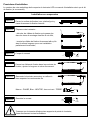


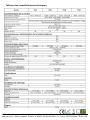
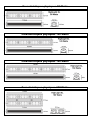
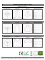
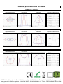
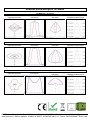
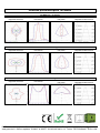
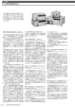


![[U2.03.04] Notice d`utilisation pour des calculs](http://vs1.manualzilla.com/store/data/006355171_1-e4204e3f6eed19ac00fe22b1d72a0ea8-150x150.png)