1
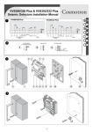
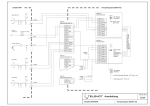
VV600 Plus & VV602 Plus
Seismic Detectors Installation Manual
1
2
GB
F
NL
D
I
E
3
4
-1-
5
6
7
1
2
GB
For further information, see the complete manual “Planning and Installation Manual VV600/602 Plus”.
F
Pour de plus amples informations, se reporter au manuel complet “Manuel d’installation du VV600S3/VV602S3 Plus”.
NL
Voor verdere informatie zie de Planning en Installatie handleiding van de VV600/602 Plus
D
Für weitere Informationen siehe Handbuch „Planung und Installation VV600/602 Plus”.
I
Per ulteriori informazioni consultare il manuale “Pianificazione ed installazione dei sensori VV600/602 Plus”
E
Para más información, ver el “Manual de Instalación y Programación del VV600/602 Plus”.
-2-
GB
1
Figure
: Wiring diagram
1/2. 12 VDC
3. LED indication
4. Integrator level
5/6. Alarm output
2
Figure
Figure
4
: Mounting the detector directly on a
metal surface without using a mounting
plate
Figure
5
: Mounting the detector on a metal
surface using the VM604P weld-on plate
7. Spare
8/9. Tamper
10. Test control
11. Spare
: Two ways to test the seismic detectors
First weld points 1, 2, 3, and 4. Then weld seams 5 and 6.
1
Test disabled (ex-factory setting)
2
Internal test of detector’s electronics = Position jumper
between 1 and 2 .
Function test of the detector and its physical contact with the
protected object = Position connector from test transmitter
VT705P between 2 and 3.
3
!
Figure
: Mounting on concrete
Always use a VM600P mounting plate. The expansion plug must
penetrate at least 50 mm into the concrete. Please follow the
steps shown in Figure 6 if you are installing the test transmitter
VT705P.
Connecting terminal 10 to 0 V activates both tests.
Figure
6
!
3 : General characteristics of the VV600/602
For the equipment to conform to CEI standard 79-2, the
VT705P test transmitter must be installed.
Plus
1.
2.
3.
4.
5.
6.
7.
8.
9.
10.
11.
12.
13.
Cover
Cover screw
Base plate
Mounting holes
Clamp
Area for mounting the VT705P test transmitter
Potentiometer for adjusting the detector’s sensitivity
Connection block
Anti-tamper micro-switch
Mounting plate VM600P
Fixing bolt
Expander bolt
Test transmitter VT705P
Figure
: Control and function test
Using a voltmeter, check the background signal level in the
detector to prevent nuisance alarms. Set the sensitivity to Gmax
during the test.
VV600 Plus
VV602 Plus
Measure
0.7 V
0V
None
1.4 V
!
Using the mounting plate VM600P as a template
A.
B.
C.
D.
E.
F.
G.
7
Holes for VV600/602 Plus
Holes for Securitas SSD70
Holes for Cerberus GM31/35/550/560
Hole for expansion plug or recess mounting box
Holes for Securitas 2000
Template and mounting holes for test transmitter VT705P
Holes for accessories.
Detection range (in meters):
2V
Try to remove the source of ambient noise instead of
reducing the range.
Functional testing with hand tester VT610P " and mechanical
tool #:
VV600 Plus
VV602 Plus
Alarm in 30 sec.
Alarm in 45 sec.
Alarm after 5 blows
NA
Technical specifications:
Input power:
Material
Concrete
Steel
Brick
Concrete
Steel
Brick
Concrete
Steel
Brick
Concrete
Steel
Brick
Concrete
Steel
Brick
Sensitivity
setting
1/Gmax
2/Gref
3/Gmin
4
5
Thermal
lance
4
8
3
3
4
1
2
2
1
1
-
Reduce range/remove source
Diamond
disk
Drilling
14
14
8
9
9
6
6
6
4
5
5
3
4
4
2
14
14
8
9
9
6
6
6
4
5
5
3
4
4
2
Current consumption:
Alarm output:
Alarm indication:
Sensitivity:
Range:
Sabotage protection:
Low voltage alarm:
Temperature limits:
Dimensions:
Colour:
Weight:
-3-
9-15 VDC
2 V max. ripple pp
Nom. 8.6 mA
Form A solid state relay, max. series
resistance 35 Ohm
LED-ind. output 3
5 steps of 6 dB each
See Table “Detection range”
Temp. 84°C,
drill shield,
opening/pry-off contact,
7.5 V
-20 °C to +55 °C
101 x 81 x 28 mm
Grey, RAL 7035
380 g
F
Figure
1/2.
3.
4.
5/6.
7.
'%: Schéma de connexion
12 V cc
Voyant LED
Niveau intégrateur
Sortie alarme
Réserve
Figure
8/9. Autoprotection
10. Test
11. Réserve
1.
2.
3.
4.
5.
6.
7.
8.
9.
10.
11.
12.
13.
$%: Deux options pour tester les détecteurs
!
&%: Schéma de montage du VV600S3/VV602S3 Plus
!
VV600S3 Plus
Alarme en 30 s
Alarme après 5 coups
Béton
Acier
Maçonnerie
Béton
Acier
Maçonnerie
Béton
Acier
Maçonnerie
Béton
Acier
Maçonnerie
Béton
Acier
Maçonnerie
1/Gmax
2/Gref
3/Gmin
4
5
e ue
nc
La rmiq
e
th
Alimentation:
4
8
3
3
4
1
2
2
1
1
-
Alarme basse tension:
Plage de température:
Dimensions:
Couleur:
Poids:
9-15 VDC
ondul. max. 2 V crête à crête
8,6 mA typique
Contact électronique NO,
résistance max. 35 ohms
Voyant LED sortie 3
Réglage en 5 pas de 6 dB
Voir le tableau
«Portée de détection»
Température 84°C,
plaque de protection contre le
perçage,
contact d’ouverture /
contre l’arrachement
7.5 V
-20 °C à +55 °C
101 x 81 x 28 mm
Gris RAL 7035
380 g
VV600S3 Plus - NF & A2P
Type 3, No.: 2730000240
IP43 IK08 UF93P2
VV602S3 Plus - NF & A2P
Type 3, No.: 2730000230
IP43 IK08 UF93P2
CNMIS
16 av Hoche
75008 Paris
Tel.: 01 53 89 00 40
Fax.: 01 45 63 40 63
CNPP
BP2265
27950 St. Marcel
Tel.: 02 32 53 63 63
Fax.: 02 32 53 64 46
Consommation:
Sortie d’alarme:
Indication d’alarme:
Sensibilité:
Rayon d’action:
Autoprotection:
t
ie
Sc m a n
dia
14
14
8
9
9
6
6
6
4
5
5
3
4
4
2
Pe
rça
VV602S3 Plus
Alarme en 45 s
–
Caractéristiques techniques :
Portée de détection (en mètres):
M
Éliminer de préférence la cause de bruit de fond au lieu de
réduire la portée.
Test fonctionnel avec testeur portable VT610P et outil mécanique:
Trous pour VV600S3/VV602S3 Plus
Trous pour Securitas SSD70
Trous pour Cerberus GM31/35/550/560
Trous pour la cheville à expansion
Trous pour Securitas 2000
Calibre et trous de montage pour le transmetteur de test VT705P
Trous pour les accessoires
e
ed
lag i l i t é
g
Ré s i b
n
se
Test de contrôle et de fonctionnement
VV600S3 Plus VV602S3 Plus Action
0,7 V
0V
Aucune
1,4 V
2V
Réduire portée/éliminer source
Utilisation de la plaque VM600P comme calibre
iau
+%:
À l’aide d’un voltmètre, vérifier le niveau de bruit de fond dans le
détecteur pour éviter les alarmes provoquées par ce type de
perturbation. Régler la sensibilité sur Gmax pendant le test.
Boîtier
Vis de fixation
Base
Orifices de montage
Serre-câble
Emplacement pour montage du vibreur de test VT705P
Potentiomètre pour réglage de la sensibilité
Bornier de connexion
Micro-interrupteur d’autoprotection
Plaque de montage VM600P
Vis de fixation
Cheville
Vibreur de test VT705P
r
até
*%: Montage sur béton
Le transmetteur de test VT705P doit être installé pour que
l’équipement soit conforme à la norme CEI 79-2.
Figure
Le raccordement de la borne 10 sur 0V active les deux tests.
Passage du câble: introduire celui(ceux)ci au travers du passage
prévu à cet effet, après avoir pratiqué une incision en croix
correspondant juste à la dimension du(des) câble(s) sur le bouchon
plastique. Le(s) couper en laissant approximativement 10 mm libres
après le serre câble.
A.
B.
C.
D.
E.
F.
G.
)%: Montage sur métal avec la plaque VM604P
Toujours utiliser une plaque de montage VM600P. La cheville doit
pénétrer d’au moins 50 mm dans la paroi. Suivre les étapes de la
figure 6 en cas d’installation du transmetteur VT705P.
Test fonctionnel du détecteur et du contact physique avec
l’objet protégé = connecteur du vibreur VT705P sur 2 et 3.
Figure
Figure
Figure
Test interne des circuits du détecteur = cavalier sur 1 et 2
!
(%: Montage sur métal sans plaque de montage
Souder d’abord les points 1, 2, 3 et 4. Puis souder les coutures 5 et 6.
Test désactivé (réglage par défaut)
1
2
3
Figure
ge
14
14
8
9
9
6
6
6
4
5
5
3
4
4
2
-4-
NL
Figuur 1
: Bedradingsdiagram
Figuur 2
: Twee manieren om de seismische
detectoren te testen
: Directe montage op metalen oppervlak:
Indien het oppervlak niet glad is
gebruik dan montageplaat VM600P of
de lasplaat VM604P
Figuur
5
: Montage van de detector op een glad
metalen oppervlak, gebruik makend van
de VM604P lasplaat
Figuur
1 en 2.
3 Interne test v/d electronica en het fysieke contact met de
ondergrond = Plaats testzender VT705P en sluit de connector aan op 2 en 3.
Klem 10 aansluiten op 0 V activeert beide test functies.
Figuur
4
Las eerst punten 1, 2, 3 en 4. Las daarna naden 5 en 6.
1 Test functie uitgeschakeld (fabrieksinstelling)
2 Interne test van de elektronica = Plaats jumper op
!
Figuur
7. Reserve
8/9. Sabotage uitgang
10. Test-stuur ingang
11. Reserve
1/2. 12 VDC
3. LED-uitgang
4. Integratorniveau
5/6. Alarmuitgang
!
Figuur
Deksel
Schroel voor bevertiging deksel
Behuizing electronica
Bevestigingsgaten
Trekontlasting
Plaats voor montage van de VT705P testzender
Potentiometer voor instelling van de detectorgevoeligheid
Aansluitconnector
Microschakelaar sabotagebeveiliging
Montageplaat VM600P
Bevestigingsschroef
Expansie bout
Testzender VT705P
ria
al
Beton
Staal
Baksteen
Beton
Staal
Baksteen
Beton
Staal
Baksteen
Beton
Staal
Baksteen
Beton
Staal
Baksteen
gh
eli
vo l i n g
e
G tel
ins
!
1/Gmax
2/Gref
3/Gmin
4
5
ijr
Sn nde
bra
4
8
3
3
4
1
2
2
1
1
-
Di
am
an
14
14
8
9
9
6
6
6
4
5
5
3
4
4
2
VV602 Plus
0V
2V
Probeer eerst de oorzaak van de omgevingsruis op te
sporen en te elimineren, voor u de gevoeligheid
vermindert.
VV600 Plus
Alarm in 30 sec.
Alarm na 5 pulsen
Technische Gegevens:
Aansluitspanning:
ijf
Bo
Meting
Geen
Verminder gevoeligheid/
verwijder storingsbron
Functionele test met handtester VT612:
h
tsc
: Controle- en functietest
VV600 Plus
0,7 V
1,4 V
Indicatief detectiebereik:
s
eid
7
Gebruik een voltmeter om het spannings niveau op punt 4 ten
gevolge van achtergrondsignaal in de detector te controleren, ter
voorkoming van ongewenst alarm. Zet de gevoeligheid op Gmax
tijdens deze test.
Gaten voor VV600/602 Plus
Gaten voor Securitas SSD70
Gaten voor Cerberus GM31/35/550/560
Gaten voor expansie bout of inbouw mantage behuizing
Gaten voor Securitas 2000
Gaten voor bevestiging van testzender VT705P
Gaten voor accessoires
te
Ma
Om de uitrusting conform CEI norm 79-2 te maken moet
de VT705P testzender geïnstalleerd worden.
3 :Algemene beschrijving van de VV600/602
Het gaten patroon in de montageplaat VM600P
A.
B.
C.
D.
E.
F
G.
: Montage op beton
Gebruik altijd een VM600P montageplaat. De expansie bout
moet minimaal 50 mm in het beton zitten. Volg de stappen in
figuur 6 als u de testzender VT705P installeert.
Plus
1.
2.
3.
4.
5.
6.
7.
8.
9.
10.
11.
12.
13.
6
Stroomverbruik:
Alarmuitgang:
or
14
14
8
9
9
6
6
6
4
5
5
3
4
4
2
Alarmindicatie:
Gevoeligheid:
Bereik:
Sabotagebeveiliging:
Alarm bij lage spanning:
Temperatuur:
Afmetingen:
Kleur:
Gewicht:
(Opgeven diameter gemeten in meters)
-5-
VV602 Plus
Alarm in 45 sec.
NVT
9-15 VDC
2 V max. rimpelspanning
Nom. 8,6 mA
Vorm A halfgeleiderrelais, max.
serieweerstand 35 ohm
LED-ind. uitgang 3
5 stappen van 6 dB elk
Zie tabel “Detectiebereik”
Temp. 84°C,
boorscherm,
openings-/loswrikcontact,
7,5 V
-20 °C tot +55 °C
101 x 81 x 28 mm
Grijs, RAL 7035
380 g
D
Abbildung
Abbildung
1 : Anschaltplan
1/2. 12 V GS
3. LED-Anzeige
4. Integratorpegel
5/6. Alarmrelais
7. Nicht belegt
Abbildung
Metalloberfläche ohne Montageplatte
8/9. Sabotage
10. Testeingang
11. Nicht belegt
Abbildung
Schweißen Sie zuerst die Punkte 1, 2, 3 und 4. Schweißen Sie
anschließend die Nähte 5 und 6.
2 : Zwei Möglichkeiten für das Testen der
Abbildung
Steckbrücke zwischen 1 und 2 einsetzen.
3 Funktionstest des Melders und dessen physikalischem
1.
2.
3.
4.
5.
6.
7.
8.
9.
10.
11.
12.
13.
!
Kontakt mit der zu überwachenden Objekt =
Anschlußstecker von VT705P-Prüfsender auf Pin 2 und 3
aufstecken.
Körperschallmelder VV600/602 Plus
Deckel
Deckelschraube
Montageplatte
Befestigungsaussparungen
Zugriffschutz für Anschlußklemmen
Montageort für den VT705P-Prüfsender
Potentiometer für die Einstellung der Melderempfindlichkeit
Anschlussklemme
Sabotage Deckelkontakt
Montageplatte VM600P
Befestigungsschraube
Spreizdübel
VT705P-Prüfsender
VV600 Plus
0,7 V
1,4 V
!
rk
We
f
Beton
Stahl
Mauerwerk
Beton
Stahl
Mauerwerk
Beton
Stahl
Mauerwerk
Beton
Stahl
Mauerwerk
Beton
Stahl
Mauerwerk
c
dli
f i n ung
p
l
E m stel
ein
Technische Angaben:
Versorgungsspannung:
1/Gmax
2/Gref
3/Gmin
4
5
Leistungsaufnahme:
Alarmausgang:
-
alerm
h
T ze
lan
4
8
3
3
4
1
2
2
1
1
-
a
Di
n
ma
14
14
8
9
9
6
6
6
4
5
5
3
4
4
2
tsc
he
Messung
Keine Anderung erforderlich
Bereich verringern/Störquelle
entfernen
Versuchen Sie, die Umgebungsgeräuschquelle zu
unterdrücken, anstatt den Bereich zu verringern.
Zubehör:
Für VdS-Installationen ist folgendes Zubehör verfügbar:
VM600P
Montageplatte für die Montage auf Beton
VM604P
Montageplatte zum Anschweißen
VT705P
Prüfsender für die Montage in VV600/602 Plus Melder
VT608N
Prüf- und Anzeigetableau für 8 VV600/602 Plus Melder
VM611N
Bodenmontagegehäuse
VM655N Verteiler in Metallgehäuse
Erfassungsbereich (in Metern):
f
sto
VV602 Plus
0V
2V
Funktionstest mit Handtester VT610P , und mechanischem Gerät -:
VV600 Plus
VV602 Plus
Alarm nach 30 Sek.
Alarm nach 45 Sek.
Alarm nach 5 Signalen
Nicht zutreffend
Aussparungen für VV600/602 Plus
Aussparungen für Securitas SSD70
Aussparungen für Cerberus GM31/35/550/560
Befestigungsaussparung für Erweiterungssteckmodul
Aussparungen für Securitas 2000
Schablone / Aussparung für VT705P-Prüfsender
Bohrungen für Zubehör
its
7 : Überwachungs- und Funktionstest
Prüfen Sie zur Vermeidung von Fehlalarmauslösungen den
Hintergrundsignalpegel anhand eines Voltmeters. Stellen Sie die
Empfindlichkeit während des Tests auf Gmax ein.
3 : Allgemeine technische Merkmale der
e
hk
Gemäß den VdS-Richtlinien und der CEI-Norm 79-2 ist
die Installation des Prüfsenders VT705-P vorgeschrieben.
Abbildung
Anschlussklemme 10 an 0 V aktiviert beide Tests.
Verwendung der VM600P-Montageplatte als Schablone
A.
B.
C.
D.
E.
F.
G.
6 : Montage auf einer Betonfläche
Verwenden Sie grundsätzlich eine VM600P-Montageplatte. Der
Spreizdübel muß mindestens 50 mm tief in den Beton
eingelassen werden. Beziehen Sie sich bitte auf die in Abbildung
6 dargestellten Schritte, wenn Sie einen VT705P-Prüfsender
verwenden.
1 Testfunktion deaktiviert (werkseitige Einstellung)
2 Interner Test der elektronischen Bestandteile des Melders =
Abbildung
5 : Montage des Melders auf einer
Metalloberfläche mit der angeschweißten
VM604P-Grundplatte
Körperschallmelder
!
4 : Direkte Montage des Melders auf einer
ibe
h
Bo
ru
ng
Alarmanzeige:
Empfindlichkeit:
Bereich:
Sabotageschutz:
14
14
8
9
9
6
6
6
4
5
5
3
4
4
2
9-15 V GS / Brummspannung
max. 2 V SS
Nennwert 8,6 mA
Solid-State Relais mit internem
35 Ohm Schutzwiderstand
LED-Ausgang /VT608N Klemme 3
5 Schritte zu je 6 dB
Vgl. Tabelle „Erfassungsbereich“
Temperatur 84 °C,
Mechanischer Bohrschutz,
Öffnungs-/Abreißkontakt,
7,5 V
-20 °C bis +55 °C
101 x 81 x 28 mm
Grau, RAL 7035
380 g
IP30 IK02
Geprüft nach Umweltklasse 2
Unterspannungsalarm:
Temperaturbereich:
Abmessungen:
Farbe:
Gewicht:
IP-Schutzart:
VdS-Umwelt:
Anerkennung:
VV600/602 Plus Standart KSM
G101141
VV602/622 Plus KSM für GAA/Nachtresore G101142
VT705P Prüfsender für KSM - Bestandteil der Melderanerkennung
VM655N Verteiler in Metallgehäuse
G189238
VT608N Prüftableau für 8 KSM
G196038
-6-
I
Figura 1
: Schema elettrico
1/2. 12 V CC
3. LED
4. Livello integrazione(test point)
5/6. Uscita allarme
Figure 2
Figura
4
: Rivelatore montato direttamente su una
superficie metallica senza piastra di
montaggio
Figura
5
: Rivelatore montato su una superficie
metallica interponendo la piastra
saldata VM604P
7. Riserva
8/9. Antimanomissione
10. Comando Test remoto
11. Riserva
: Due modalità per testare i rivelatori
sismici
Saldare prima i punti 1, 2, 3 e 4. Quindi saldare i bordi 5 e 6.
1 Possibilità di test disabilitata (impostazione predefinita in
fabbrica)
2 Test interno, dell’elettronica del rivelatore = posizionare il
Figura
ponticello fra 1 e 2.
3 Test funzionale del rivelatore e del contatto fisico con
l’oggetto protetto = posizionare il connettore del trasmettitore
di prova VT705P fra 2 e 3.
!
1.
2.
3.
4.
5.
6.
7.
8.
9.
10.
11.
12.
13.
!
: Caratteristiche generali del VV600/602
Plus
Coperchio
Vite coperchio
Piastra di base
Fori di montaggio
Morsetto
Aree per il montaggio del trasmettitore di prova VT705P
Potenziometro per regolare la sensibilità del rivelatore
Morsettiera
Microinterruttore antimanomissione
Piastra di montaggio VM600P
Vite di fissaggio
Tassello ad espansione
Trasmettitore di prova VT705P
VV600 Plus
0,7 V
1,4 V
!
M
ale
Cemento
Acciaio
Muratura
Cemento
Acciaio
Muratura
Cemento
Acciaio
Muratura
Cemento
Acciaio
Muratura
Cemento
Acciaio
Muratura
1/Gmax
2/Gref
3/Gmin
4
5
4
8
3
3
4
1
2
2
1
1
-
to
o
sc n t a
Di m a
dia
14
14
8
9
9
6
6
6
4
5
5
3
4
4
2
: Test di controllo e funzionale
VV602 Plus
0V
2V
è preferibile cercare di eliminare la sorgente del rumore
ambientale, piuttosto che ridurre la portata.
VV600 Plus
Allarme entro 30 sec.
Allarme dopo 5 colpi
P
Azione correttiva
Nessuna
Ridurre la portata/eliminare la
sorgente di rumore
Test funzionale con tester palmare VT610P e attrezzo meccanico
Range di rivelazione (in metri):
ri
ate
7
Onde evitare falsi allarmi, utilizzando un voltmetro controllare il
livello del segnale di disturbo di fondo nel rivelatore . Impostare
la sensibilità su Gmax durante il test.
Fori per VV600/602 Plus
Fori per Securitas SSD70
Fori per Cerberus GM31/35/550/560
Foro di fissaggio per inserire la vite a espansione
Fori per Securitas 2000
Foro modello per trasmettitore di prova VT705P
Fori per accessori
e
ion
taz à
s
ia
p o ilit
nc
I m sib
La mica
n
e
r
s
te
per la conformità dell’apparecchio alle norme CEI 79-2,
occorre installare il trasmettitore di prova VT705P.
Figura
Utilizzo della piastra di montaggio VM600P come
modello
A.
B.
C.
D.
E.
F.
G.
: Montaggio su cemento
Utilizzare sempre una piastra di montaggio VM600P. Il tassello
ad espansione deve penetrare almeno di 50 mm nel cemento.
Se si installa il trasmettitore di prova VT705P, procedere secondo
le fasi illustrate nella figura 6.
collegando il morsetto 10 ad un riferimento 0V si
attivano entrambi i test.
Figura 3
6
or
erf
azi
on
e
14
14
8
9
9
6
6
6
4
5
5
3
4
4
2
-7-
VV602 Plus
Allarme entro 45 sec.
N/A
Dati tecnici: Conforme alle norme CEI 79-2
Alimentazione
9-15 VDC (12 VDC nom.)
Ondulazione max. residua 2 Vpp
Consumo di corrente
Nominale 8,6 mA
Uscita allarme
Relè a stato solido contatto NC,
resistenza in serie max. 35 Ohm
Indicazione allarme
Indicazione a LED, morsetto 3
Sensibilità
5 scatti di 6 dB ciascuno
Portata
Vedere tabella “Portata di rivelazione”
Protezione antisabotaggio Temp. 84°C, piastra di protezione
antitrapanazione, contatto su
apertura del coperchio e
antirimozione, allarme bassa livello
alimentazione 7,5 V
Temperatura di esercizio
da -20°C a +55°C
certificato
da + 5 a + 40 °C
Dimensioni
101 x 81 x 28 mm
Colore
Grigio RAL 7035
Peso
380 g
E
Figura 1 : Esquema eléctrico
Figura 4 :
Montaje del detector directamente
sobre una superficie metálica sin usar placa
de montaje
7. Libre
8/9. Sabotaje
10. Control de pruebas
11. Libre
1/2. 12 V CC
3. Indicador LED
4. Ruido de fondo
5/6. Alarma
Figura 5 :
Montaje del detector sobre una
superficie metálica utilizando la placa de
soldadura VM604P
Figura 2 : Dos formas de probar los sísmicos
Prueba desactivada (ajuste de fábrica)
Suelde primero los puntos 1, 2, 3 y 4. A continuación, ponga un
cordón de soldadura en los puntos 5 y 6.
1 Prueba interna de los componentes electrónicos del detector
= Posición del puente entre 1 y 2.
2
Prueba de funcionamiento del detector y su contacto físico
con el objeto protegido = Posición del conector desde el
3 transmisor de pruebas VT705P entre 2 y 3.
!
Figura
Utilice siempre una placa de montaje VM600P. El taco metálico
debe penetrar al menos 50 mm en el hormigón. Siga los pasos
mostrados en la figura 6 si va a instalar el transmisor de pruebas
VT705P.
Con 0 V en el terminal de conexión 10 se activan ambas
pruebas.
!
Figura 3 :Características generales del VV600/602 Plus
1.
2.
3.
4.
5.
6.
7.
8.
9.
10.
11.
12.
13.
Tapa
Tornillo de la tapa
Placa base
Orificios de montaje
Abrazadera
Lugar de montaje del transmisor de pruebas VT705P
Potenciómetro para ajustar la sensibilidad del detector
Bloque de conexión
Microinterruptor antiforzamientos
Placa de montaje VM600P
Tornillo de fijación
Taco metálico
Transmisor de pruebas VT705P
Para que el equipo cumpla la norma CEI 79-2, debe
haber instalado un transmisor de pruebas VT705P.
Figura 7 : Prueba de control y funcionamiento
Utilizando un voltímetro, compruebe el nivel de la señal de fondo
en el detector para evitar falsas alarmas. Ajuste la sensibilidad a
Gmáx durante la prueba.
VV600 Plus
0,7 V
1,4 V
!
Uso de la placa de montaje VM600P como plantilla
A.
B.
C.
D.
E.
F.
G.
6 : Montaje sobre hormigón
Orificios para VV600/602 Plus
Orificios para Securitas SSD70
Orificios para Cerberus GM31/35/550/560
Orificio de fijación para insertar el tornillo de fijación
Orificios para Securitas 2000
Orificio de la plantilla para el transmisor de pruebas VT705P
Orificios para accesorios
VV602 Plus
0V
2V
Trate de eliminar la fuente del ruido ambiente en lugar
de reducir el alcance.
Prueba de funcionamiento con el comprobador manual VT610P
y la herramienta mecánica:
VV600 Plus
Alarma en 30 segundos
Alarma después de 5 golpes
Rango de detección (en metros):
te
Ma
ria
l
Hormigón
Acero
Ladrillo
Hormigón
Acero
Ladrillo
Hormigón
Acero
Ladrillo
Hormigón
Acero
Ladrillo
Hormigón
Acero
Ladrillo
1/Gmax
2/Gref
3/Gmin
4
5
4
8
3
3
4
1
2
2
1
1
-
VV602 Plus
Alarma en 45 segundos
No corresponde
Especificaciones técnicas:
Alimentación:
de a d
a
te
nz
us i b i l i d
j
L a mica
A ns
r
té
se
Acción
Ninguna
Reduzca el alcance/elimine la
fuente de ruido
e
od
sc a n t e
i
D m
dia
14
14
8
9
9
6
6
6
4
5
5
3
4
4
2
© Aritech is an Interlogix company. 2002. All rights reserved.
Pe
rfo
rac
ión
Consumo:
Salida de alarma:
14
14
8
9
9
6
6
6
4
5
5
3
4
4
2
Indicación alarma:
Sensibilidad:
Alcance:
Protección contra sabotajes:
Alarma por baja tensión:
Límites de temperatura:
Dimensiones:
Color:
Peso:
-8-
9-15 V CC
2 V máx. pp
8,6 mA nom.
Relé de estado sólido forma A,
resistencia máx. en serie
35 ohmios
Indicador LED terminal3
5 pasos de 6 dB cada uno
Consulte la tabla “Alcance de
detección”
Temp. 84°C,
protección contra perforación,
contacto de apertura/sabotaje por
palanca
7,5 V
De -20 °C a +55°C
101 x 81 x 28 mm
Gris, RAL 7035
380 g
4205-2A


![Un exemple d`utilisation du Code_Aster : calcul d`[...]](http://vs1.manualzilla.com/store/data/006378765_1-78c84f9e3de587cd857dc1c0e3a3a2a6-150x150.png)