1
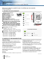
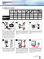
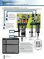
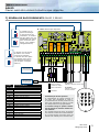
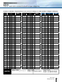
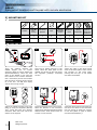
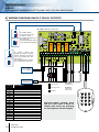
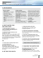
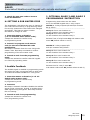
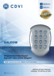
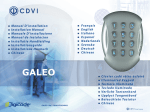
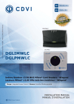
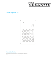
* Voir conditions de garantie à vie limitée. / Refer to Limited Lifetime Warranty.
FR
FRANCAIS
EN
ENGLISH
GALEO
Clavier codé rétro-éclairé étanche
Illuminated weatherproof keypad with remote electronics
®
Range: Digicode / Gamme: Digicode
®
INSTALLATION MANUAL
MANUEL D’INSTALLATION
Group Products
MANUEL D’INSTALLATION
GALEO
Clavier codé rétro-éclairé à électronique déportée
Merci pour l’achat de ce produit et pour la confiance que vous accordez
à notre entreprise.
1] PRESENTATION DU PRODUIT
Alliage d’aluminium.
Rétro-éclairé.
Faible encombrement.
TANCE
HAUTE RESIS
De 2 à 3 relais.
ISME
AU VANDAL
Pose en applique.
Free voltage*.
Montage avec vis Torx®.
Etanchéité du clavier (surmoulé).
Protection de la carte électronique
déportée par tropicalisation.
100 codes d’accès personnalisables
individuellement par chaque utilisateur.
Existe en version Wiegand (GALEOW).
-
Signalisation lumineuse et sonore.
Dimensions (L x l x P) :
- GALEO = 110 x 75 x 15 mm,
- Electronique déportée = 147 x 124 x 55 mm.
Alimentations : 12 V à 24 V AC et 12 V à 48 V DC.
Consommation (3 relais commandés + clavier) :
En 12 V AC : Au repos 90 mA,
En 24 V AC : Au repos 46 mA,
En 12 V DC : Au repos 100 mA,
En 24 V DC : Au repos 55 mA,
En 48 V DC : Au repos 30 mA.
Test vibrations
DEEE
Test brouillard salin
IP64
Certification CE
-25°C à +70°C
ELECTRONIQUE DÉPORTÉE
Certification CE
IP52
DEEE
-20°C à +70°C
2] RAPPELS ET RECOMMANDATIONS
Rappel de câblage
La distance de câblage entre le GALEO et l’électronique déportée doit être au maximum de 10 m.
Attention de ne pas passer vos fils à proximité de
câbles «Courant fort» (ex: 230 V AC).
Câbles préconisés entre le GALEO
et l’électronique déportée
Pour une extension du câble 3 mètres fourni, privilégiez
un câble 2 paires (4 fils) SYT1 8/10ème (AWG 20).
Alimentations préconisées
ARD12 et BS60
Montage
Afin d’optimiser la fixation du GALEO et de prévenir les
tentatives d’arrachage, privilégiez les surfaces planes.
Composition des codes
Par soucis de sécurité, veillez à modifier le code
maître usine par celui de votre choix. Lors du
changement du code maître usine et de la création
des codes utilisateurs, évitez les codes trop simples
(ex: les suites 3 4 5 6 7).
Recommandations d’installation
Pour sécuriser l’installation, n’oubliez pas de placer
la varistance sur le système de verrouillage, en
parallèle, au niveau de l’alimentation. L’électronique déportée du GALEO doit être impérativement
installée dans un environnement clos et protégée
des conditions climatiques extérieures.
* Tension libre.
2
cdvi.com
cdvigroup.com
MANUEL D’INSTALLATION
GALEO
Clavier codé rétro-éclairé à électronique déportée
3] ÉLÉMENTS FOURNIS
Varistance
Vis Torx®
à tête
fraisée
(M4x10)
Clé mâle
coudée
pour vis
Torx® (T20)
Cache vis
Vis
cruciforme
à tête fraisée
(M4x30)
Cheville
plastique
Passe fil
Plaque de
fixation de
l’électronique
déportée
GALEO
1
1
1
2
2
2
-
-
Electronique
déportée
-
-
-
-
2
2
2
1
4] MONTAGE
1
2
3
®
®
GALEO
GALEO
Vérifiez la distance entre le GALEO
et son électronique déportée (Voir
page 2 «Rappels et préconisations»).
A l’aide de la plaque de fixation de
l’électronique déportée et du GALEO,
prenez les marques et percez les
2 trous de fixation (forêt Ø 5 mm et
profondeur minimum. = 35 mm) ainsi
que l’ouverture pour le passage du
câble électrique destiné au clavier.
4
GALEO
GALEO
GALEO
®
®
Positionnez les 2 chevilles plastiques
dans les trous. Puis Fixez le fond du
GALEO sur le support de votre choix,
à l’aide des vis cruciformes à têtes
fraisées.
5
®
GALEO
®
Passez le câble électrique du GALEO
dans son ouverture et fixez le à son
support par le haut avec le crochet
supérieur.
6
(x2)
(x2)
(x2)
®
®
ALEO GALEO
Bloquez le GALEO sur son support
par l’intermédiaire de la vis TORX®
et de son outil spécifique (clé mâle
coudée). Pour finaliser le montage
de ce produit, placez le cache-vis.
Positionnez les 2 chevilles plastique
dans les trous. Puis fixez la plaque de
fixation de l’électronique déportée
sur la surface de votre choix, à l’aide
des vis cruciformes à têtes fraisées.
Venez ensuite placer l’électronique
déportée sur son support.
Passez vos fils, glissez les passe-fils
de l’électronique déportée et faites
vos branchements. Lors de cette
opération, n’oubliez pas de placer la
varistance (Voir page 2 «Rappels et
préconisations»).
cdvi.com
cdvigroup.com
3
MANUEL D’INSTALLATION
GALEO
Clavier codé rétro-éclairé à électronique déportée
6] SCHÉMA DE RACCORDEMENTS GALEO 2 RELAIS
Electronique déportée
Le cavalier sur P3
permet de changer
le code d’entrée par
l’utilisateur. Le cavalier
doit être placé pour les
modifications et enlevé
pour verrouiller cette
option. (voir chapitre
«Programmation»)
Blanc
Le cavalier sur P2 permet
de réaliser une remise
à zéro de la mémoire.
Le cavalier doit être placé
hors tension pour que la
manipulation fonctionne
(voir chapitre «Programmation»)
Alimentation
12 à 24 V AC
ou 12 à 48 V DC
Alimentation
côté puissance
de commande
Sortie
4
Correspondance
V
Alimentation 12V à 24V AC ou 12V à 48V DC
V
Alimentation 12V à 24V AC ou 12V à 48V DC
R1
Contact repos du relais 1
C1
Commun du relais 1
T1
Contact travail du relais 1
R2
Contact repos du relais 2
C2
Commun du relais 2
T2
Contact travail du relais 2
P1
Bouton intérieur de sortie relais 1
M
Commun boutons
P2
Bouton intérieur de sortie relais 2
H
Contact horloge
+
Clavier fil blanc
-
Clavier fil marron
E
Clavier vert ou bleu ( éclairage )
cdvi.com
cdvigroup.com
Gâche à rupture
(Contact au repos)
Gâche à émission
Varistance
H (Ouvert)
GALEO en fonction clavier codé
H (Fermé)
GALEO en fonction
Bouton Poussoir
Commande par bouton poussoir
Le raccordement du bouton poussoir P1 est
prévu pour commander le relais 1. Le raccordement du bouton poussoir P2 est prévu
pour commander le relais 2. Le mode et la
temporisation sont programmables.
Le contact horloge H permet l’utilisation de toutes les touches comme bouton extérieur.
Si le contact horloge est ouvert, les touches
sont utilisées comme des termes habituels.
Si le contact horloge est fermé, toutes les
touches sont utilisées pour l’ouverture libre.
Vert ou bleu
Relais 2
Marron
Relais 1
MANUEL D’INSTALLATION
GALEO
Clavier codé rétro-éclairé à électronique déportée
7] SCHÉMA DE RACCORDEMENTS GALEO 3 RELAIS
D - 693 : Electronique déportée
Le cavalier sur P3
permet de changer
le code d’entrée par
l’utilisateur. Le cavalier
doit être placé pour les
modifications et enlevé
pour verrouiller cette
option. (voir chapitre
«Programmation»)
Relais 3
Blanc
Le cavalier sur P2 permet
de réaliser une remise
à zéro de la mémoire.
Le cavalier doit être placé
hors tension pour que la
manipulation fonctionne
(voir chapitre «Programmation»)
Alimentation
12 à 24 V AC
ou 12 à 48 V DC
Alimentation
côté puissance
de commande
Correspondance
Gâche à rupture
(Contact au repos)
V
Alimentation 12V à 24V AC ou 12V à 48V DC
Gâche à émission
V
Alimentation 12V à 24V AC ou 12V à 48V DC
Sortie
R1
Contact repos du relais 1
C1
Commun du relais 1
T1
Contact travail du relais 1
R2
Contact repos du relais 2
C2
Commun du relais 2
T2
Contact travail du relais 2
R3
Contact repos du relais 3
C3
Commun du relais 3
T3
Contact travail du relais 3
P1
Bouton intérieur de sortie relais 1
M
Commun boutons
P2
Bouton intérieur de sortie relais 2
H
Contact horloge
+
Clavier fil blanc
-
Clavier fil marron
E
Clavier vert ou bleu ( éclairage )
Varistance
Vert ou bleu
Relais 2
Marron
Relais 1
H (Ouvert)
GALEO en fonction clavier codé
H (Fermé)
GALEO en fonction
Bouton Poussoir
Commande par bouton poussoir
Le raccordement du bouton poussoir P1
est prévu pour commander le relais 1.
Le raccordement du bouton poussoir P2 est
prévu pour commander le relais 2. Le mode
et la temporisation sont programmables.
Le contact horloge H permet l’utilisation de toutes les touches comme bouton extérieur.
Si le contact horloge est ouvert, les touches
sont utilisées comme des termes habituels.
Si le contact horloge est fermé, toutes les
touches sont utilisées pour l’ouverture libre.
cdvi.com
cdvigroup.com
5
MANUEL D’INSTALLATION
GALEO
Clavier codé rétro-éclairé à électronique déportée
8] PROGRAMMATION
Tapez 2 fois
le code Maître
2 bips sonores
Temporisation
éclairage clavier
Temporisation
relais 1
Temporisation
relais 2
Temporisation
relais 3
Nombre de
termes
Code maitre
A0
A1
A2
A3
A4
A5
1 bip
1 bip
1 bip
1 bip
1 bip
1 bip
10-99 sec
00 = continue
01-99 sec
00 = continue
01-99 sec
00 = continue
01-99 sec
00 = continue
4’ ou 5’
Tous les
boutons sont
valides
10 = Défaut
01 = Défaut
01 = Défaut
01 = Défaut
1 bip = OK
(4 bips = Erreur)
1 bip = OK
(4 bips = Erreur)
1 bip = OK
(4 bips = Erreur)
1 bip = OK
(4 bips = Erreur)
GALEO
GALEO3R
6
cdvi.com
cdvigroup.com
05 = Défaut
1 bip = OK
(4 bips = Erreur)
12345=Défaut
1 bip = OK
(4 bips = Erreur)
MANUEL D’INSTALLATION
GALEO
Clavier codé rétro-éclairé à électronique déportée
Reset
Termes de
modification
relais 1
Termes de
modification
relais 2
Termes de
modification
relais 3
Signal
sonore
Programmation
des codes
A6
A7
A8
A9
AA
00-99
1 bip
1 bip
1 bip
1 bip
1 bip
2
chiffres
2
chiffres
2
chiffres
AB=défaut
13=défaut
46=défaut
1 bip = OK
(4 bips = Erreur)
1 bip = OK
(4 bips = Erreur)
1 bip = OK
(4 bips = Erreur)
A
GALEO
GALEO3R
4’ ou 5’ chiffres
-----------------4 bips =
Rang occupé
1 bips =
Rang libre
0 = Supprimer
les bips
1 = Autoriser
les bips
1 bip = OK
(4 bips = Erreur)
1 bip = OK
B
2 bips sonores
cdvi.com
cdvigroup.com
7
MANUEL D’INSTALLATION
GALEO
Clavier codé rétro-éclairé à électronique déportée
5] PROGRAMMATION
LES VALEURS DU GALEO
SONT PAR DÉFAUT:
- Sans codes.
- Temporisation éclairage : 10 s.
- Temporisation d’ouverture pour
tous les relais : 1 secondes.
- Nombre de termes : 5.
- Code maître usine : 1 2 3 4 5.
- Temporisation sécurité
programmation : 120 secondes.
- Termes de modification par
utilisateur :
Version 1 relais (Groupe 1) =
A et B,
Version 2 relais (Groupe 2) =
1 et 3
Version 3 relais (Groupe 3) =
4 et 6.
Le code maître et les codes
d’ouverture de porte doivent
être composés de 4 ou 5 termes.
SIGNAUX SONORES :
Le code maître ne peut pas être
- 1 bip court = Mise sous tension.
utilisé comme code d’ouverture.
- 1 bip long = Validation d’une
Les codes 00000 et 0000 servent
saisie en programmation
à annuler un code existant
ou ouverture autorisée.
et ne peuvent donc pas servir
- 2 bips courts = Entrée
comme code d’ouverture de porte.
ou sortie de programmation.
- 4 bips courts = Erreur de saisie. CAVALIER P2
Code maître usine 1 2 3 4 5
TERMES UTILISÉS ET CODES
et RAZ des codes.
D’OUVERTURE:
Toutes les touches du clavier
CAVALIER P3
Modification des codes
sont autorisées pour composer
par l’utilisateurs.
les codes.
A. REMISE À ZÉRO DE LA MÉMOIRE
1. Tapez 2 fois le code maître.
Pour la première utilisation, le code maître usine
est : 1 2 3 4 5.
Deux bips sonores sont émis pour confirmer
l’entrée en programmation.
2. Puis tapez A6.
Un bip sonore est émis.
3. Tapez A et B
La remise à zéro est validée.
Attendez que deux bips soient émis. Le code maître
est de nouveau 1 2 3 4 5 et tous les codes sont
effacés. Le clavier est sorti de programmation
et les valeurs par défaut sont rétablies.
Vous avez aussi une seconde possibilité pour
remettre à zéro la mémoire
1. Coupez l’alimentation et positionnez
un cavalier en P2.
Pour avoir plus de précision sur l’emplacement
du cavalier P2, reportez vous à la page 4.
2. Rétablir l’alimentation.
Attendre environ 3 secondes. 2 bips sonores
sont émis pour confirmer la remise à zéro.
Enlevez le cavalier P2. Le code maître est de nouveau
1 2 3 4 5 et tous les codes sont effacés. Les valeurs
par défaut sont rétablies.
8
cdvi.com
cdvigroup.com
B. PROGRAMMATION DU CODE
MAÎTRE ET DU NOMBRE DE TERMES
1. Tapez 2 fois le code maître.
Pour la première utilisation, le code maître usine
est : 1 2 3 4 5. Deux bips sonores sont émis
pour confirmer l’entrée en programmation.
2. Tapez A4 pour la saisie du nombre de
termes des codes.
Un bip est émis. Tapez 4 ou 5 pour le nombre
de termes. Un bip sonore est émis pour confirmer
la programmation.
3. Tapez A5 pour changer le code maître.
Un bip est émis. Tapez les 4 ou 5 termes
du nouveau code maître. Un bip sonore est émis
pour confirmer la programmation.
4. Tapez B pour sortir de la programmation.
Deux bips sont émis pour confirmer le retour
au mode normal de fonctionnement.
4 bips indiquent une erreur de saisie.
Cas de figure :
Vous avez un code maître et des codes utilisateurs
à 5 termes. Vous souhaitez utiliser des codes
à 4 termes. Vous faites donc la démarche indiquée
ci-dessus en modifiant le code maître. Lorque
le nombre de terme du code maître est bien passé
de 5 à 4 termes, les codes utilisateurs deviennent
simultanément des codes à 4 termes.
MANUEL D’INSTALLATION
GALEO
Clavier codé rétro-éclairé à électronique déportée
Ex : Si votre code maître et code utilisateur
est 1 2 3 6 9, il deviendra après manipulation
2 3 6 9. Si vous souhaitez passer d’un code maître
(et donc d’un code utilisateur) de 4 termes à 5
termes suivez la même procédure. Lors du passage
de 4 à 5 termes, le chiffre «O» sera intégrer
par défaut devant le code maître et donc devant
les codes utilisateurs.
Ex : le passage du code maître 2 3 6 9 à 4 termes
en 5 termes devient 0 2 3 6 9.
Il est conseillé de programmer les codes
en 5 termes puis de modifier
le nombre de termes.
C. PROGRAMMATION DU CODE
MAÎTRE
1. Tapez 2 fois le code maître.
Pour la première utilisation, le code maître usine
est : 1 2 3 4 5. Deux bips sonores sont émis
pour confirmer l’entrée en programmation.
2. Tapez A5.
Un bip est émis. Tapez les 4 ou 5 termes
du nouveau code maître. Un bip sonore est émis
pour confirmer la programmation.
3. Tapez B pour sortir de la programmation.
Deux bips sont émis pour confirmer le retour
au mode normal de fonctionnement.
D. PROGRAMMATION DES CODES
Suivant le nombre de relais de votre GALEO
(1,2 ou 3 relais) les groupes de codes (appellés
aussi rangs pour le classements des codes par
individus) sont différents :
GALEO 1 Relais
Groupe 1 : Du rang 00 au rang 99.
GALEO 2 Relais
Groupe 1 : Du rang 00 au rang 59,
Groupe 2 : Du rang 60 au rang 99.
GALEO 3 Relais
Groupe 1 : Du rang 00 au rang 59,
Groupe 2 : Du rang 60 au rang 79,
Groupe 3 : Du rang 80 au rang 99.
1. Tapez 2 fois le code maître.
Pour la première utilisation, le code maître usine
est : 1 2 3 4 5. Deux bips sonores sont émis
pour confirmer l’entrée en programmation.
2. Tapez le n° du rang à programmer
(en fonction du nombre de relais de votre GALEO).
Si le rang est libre, tapez les 4 ou 5 termes
du code. Si le rang est occupé, 4 bips sont émis.
Tapez les 4 ou 5 termes du code ou tapez 0 0 0 0
0 ou 0 0 0 0 pour annuler le code enregistré.
Un bip sonore est émis pour confirmer
la programmation.
3. Tapez B pour sortir de la programmation.
Deux bips sont émis pour confirmer le retour
au mode normal de fonctionnement.
Si le code composé correspond à un code
existant ou s’il est identique au code
maître, 4 bips sonores indiquent
une erreur. Les codes 00000 et 0000
servent à annuler un code existant
et ne peuvent donc pas servir comme code
d’ouverture de porte.
E. PROGRAMMATION
DES TEMPORISATIONS
1. Tapez 2 fois le code maître.
Pour la première utilisation, le code maître usine
est : 1 2 3 4 5. Deux bips sonores sont émis
pour confirmer l’entrée en programmation.
2. Tapez A0 pour la temporisation du clavier.
Un bip sonore est émis. Tapez la durée de commande
en secondes.
Ex : De 10 pour 10 secondes à 99 pour 99
secondes ou tapez 00 pour obtenir un éclairage
permanent. Un bip sonore de validation est émis.
3. Relais 1 (Groupe 1) : Tapez A1.
Relais 2 (Groupe 2) : Tapez A2.
Relais 3 (Groupe 3) : Tapez A3.
Cette manipulation vous permet de gérer
la temporisation des relais. Vous devez réaliser
la démarche pour chacun des relais de votre
GALEO. Un bip sonore est émis. Tapez la durée
de commande en secondes.
cdvi.com
cdvigroup.com
9
MANUEL D’INSTALLATION
GALEO
Clavier codé rétro-éclairé à électronique déportée
Ex : De 01 pour 1 seconde à 99 pour 99 secondes.
La durée 00 correspond au fonctionnement bistable
du relais. Un bip sonore de validation est émis.
4. Pour sortir de la programmation, tapez B.
Deux bips sonores sont émis pour confirmer
le retour au mode normal de fonctionnement.
4 bips indiquent une erreur de saisie.
F. REMISE À ZÉRO DU CODE MAÎTRE
En fonctionnement normal, positionnez un cavalier
en P2. Attendre 1 seconde et enlevez le cavalier.
Un bip est émis. Le code maître est de nouveau
1 2 3 4 5 en 5 termes ou 1 2 3 4 en 4 termes.
1. Tapez 2 fois le code maître.
Pour la première utilisation, le code maître usine
est : 1 2 3 4 5. Deux bips sont émis pour confirmer
l’entrée en programmation.
2. Relais 1 (Groupe 1) : Tapez A7.
Relais 2 (Groupe 2) : Tapez A8.
Relais 3 (Groupe 3) : Tapez A9.
Suivant le nombre de relais, cette saisie
vous permettra de composer les nouveaux termes
de modifications des codes utilisateurs pour chaque
groupe. Un bip est émis. Tapez les deux termes
de modification. Un second bip sonore est émis
pour confirmer la programmation.
Ex: GALEO 3 Relais, Tapez A7 puis composez
les deux termes de modifications. Puis répétez
l’opération en tapant A8 et une nouvelle fois
en composant A9.
G. CHANGEMENT DU CODE
D’ENTRÉE PAR L’UTILISATEUR
3. Tapez B pour sortir de la programmation.
Deux bips sont émis pour confirmer le retour
au mode normal de fonctionnement.
L’autorisation de changement de code par l’utilisateur
est déterminée par le positionnement du cavalier
P3 (Otez le cavalier pour interdire le changement
de code, et placez le cavalier pour autoriser
le changement ).
I. PROGRAMMATION DU SIGNAL
SONORE
1. Composez le code utilisé actuellement.
Le relais d’ouverture est commandé. Un bip sonore
est émis.
2. Tapez immédiatement les 2 termes
du code de modification.
Relais 1, à la première utilisation : A et B.
Relais 2, à la première utilisation : 1 et 3.
Relais 3, à la première utilisation : 4 et 6.
Un bip sonore est émis pour autoriser
le changement.
3. Composez le nouveau code d’ouverture.
Deux bips sonores confirment la validation du nouveau
code et le retour à un fonctionnement normal.
4. Vérifiez la mémorisation du nouveau code
en le composant.
H. PROGRAMMATION DES TERMES
DE MODIFICATIONS
10
cdvi.com
cdvigroup.com
Le signal sonore est toujours audible en programmation.
Il en est de même lors de la commande d’ouverture,
suite à la reconnaissance d’un code. Par défaut,
lors de la composition du code d’ouverture, aucun
bip sonore «touche» n’est audible. Il est possible
d’autoriser les bips a sonores touches :
1. Tapez 2 fois le code maître.
Pour la première utilisation, le code maître usine
est : 1 2 3 4 5. Deux bips sonores sont émis pour
confirmer l’entrée en programmation.
2. Tapez AA.
Un bip est émis. Tapez 0 pour supprimer les bips
touches pendant la composition du code d’ouverture.
Tapez 1 pour autoriser les bips touches pendant
la composition du code d’ouverture. Un bip sonore
est émis pour confirmer la programmation.
3. Tapez B pour sortir de la programmation.
Deux bips sonores sont émis pour confirmer
le retour au mode normal de fonctionnement.
MANUEL D’INSTALLATION
GALEO
Clavier codé rétro-éclairé à électronique déportée
Ci-joint un tableau récapitulatif qui vous servira à indiquer le code attribué à chaque utilisateur
Rangs
Code
Nom
Prénom
Rangs
Code
Nom
Prénom
Rangs
00
34
68
01
35
69
02
36
70
03
37
71
04
38
72
05
39
73
06
40
74
07
41
75
08
42
76
09
43
77
10
44
78
11
45
79
12
46
80
13
47
81
14
48
82
15
49
83
16
50
84
17
51
85
18
52
86
19
53
87
20
54
88
21
55
89
22
56
90
23
57
91
24
58
92
25
59
93
26
60
94
27
61
95
28
62
96
29
63
97
30
64
98
31
65
99
32
66
33
67
RAPPEL
GALEO 1 Relais
Groupe 1 : Du rang 00 au rang 99.
GALEO 2 Relais
Groupe 1 : Du rang 00 au rang 59,
Groupe 2 : Du rang 60 au rang 99.
Code
Nom
Prénom
GALEO 3 Relais
Groupe 1 : Du rang 00 au rang 59,
Groupe 2 : Du rang 60 au rang 79,
Groupe 3 : Du rang 80 au rang 99.
cdvi.com
cdvigroup.com
11
MANUEL D’INSTALLATION
GALEO
Clavier codé rétro-éclairé à électronique déportée
8] CONDITIONS DE GARANTIE À VIE LIMITÉE [EXTRAIT]*
Les sociétés CDVI garantissent que ce produit est dépourvu de tout vice caché, tant dans les matériaux
que dans sa fabrication, à la condition, qu’il soit installé conformément aux préconisations du fabricant
et qu’il n’y ait pas eu d’interventions ou de modifications sur le produit. La responsabilité de CDVI se limite
à la réparation ou à l’échange du produit. CDVI n’assume aucune responsabilité concernant les dommages
sur les biens ou les personnes. Un produit reconnu défectueux par CDVI doit être retourné au serviceaprès-vente de CDVI, après l’obtention du numéro d’autorisation de Retour de Produit(s) Défectueux (RMA).
La responsabilité de CDVI se limite à la réparation ou au remplacement d’un produit ou pièces défectueuses,
en ses ateliers. L’une ou l’autre de ces interventions sont définis par le service-après-vente de CDVI.
Le préjudice imputable à CDVI ne saurait en aucun cas dépasser la valeur du produit. La responsabilité
de CDVI ne peut être engagée auprès de l’acheteur, installateur, client final ou qui que ce soit, lors de dommages
consécutifs à des imperfections ou mauvais fonctionnement du produit. Cette garantie prend effet
à la date d’enregistrement du produit auprès de CDVI, à partir de l’instant ou la date d’enregistrement est
dûment complétée, dans la limite d’un mois, après la date de livraison au client final. Pour obtenir les détails complets de cette garantie et enregistrer votre/vos produit(s) pour bénéficier de cette « Garantie à Vie
limitée ». Veuillez compléter la carte d’enregistrement présente dans la boite du produit et nous la retourner,
par email ou par courrier, à l’adresse de l’entité CDVI la plus proche ou vous enregistrer en ligne à l’adresse
www.cdvigroup.com. Les contacts des entités CDVI sont accessibles en ligne à l’adresse www.cdvigroup.com
ou au dos de la notice d’installation.
EXCLUSIONS DE LA GARANTIE : A l’EXCEPTION DES POINTS EVOQUES PRECEDEMMENT, CDVI N’APPLIQUE
AUCUNE GARANTIE, NI DELIBEREE NI TACITE, A TOUS LES PROBLEMES INCLUANT LE CONDITIONNEMENT,
LE TRANSPORT, LEUR COMMERCIALISATION OU LES CONDITIONS D’UTILISATIONS PARTICULIÈRES.
9] NOTES
*Voir conditions de garantie à vie limitée
12
cdvi.com
cdvigroup.com
INSTALLATION MANUEL
GALEO
Illuminated Weatherproof Keypad with remote electronics
Thank you for buying our products and for the confidence you placed
in our company.
1] GENERAL INFORMATION
Polished heavy duty Zamak® cast alloy.
Backlit keys.
2 to 3 relays.
Surface mount.
TANCE
HIGH RESIS
ISM
TO VANDAL
Free voltage.
Mounting with Torx® screws
Keypad sealed with epoxy.
PCB of remote electronics protected
with a varnish coating.
100 user codes customisable
by each user.
Available in Wiegand version (GALEOW).
Audible and visual feedback.
Dimensions (L x W x D):
GALEO = 110 x 75 x 15mm,
Remote Controller = 147 x 124 x 55mm.
Power supplies: 12V to 24V ac and 12V to 48V dc.
Consumption (when 3 relay outputs activated.
and keypad illuminated):
- 12V AC: Standby 90mA,
- 24V AC: Standby 46mA,
- 12V DC: Standby 100mA,
- 24V DC: Standby 55mA,
- 48V DC: Standby 30mA.
Environmental tests:
vibrations
WEEE
Environmental test:
Salt spray
IP64
CE certification
-25°C to +70°C
REMOTE CONTROLLER
CE certification
IP52
WEEE
-20°C to +70°C
2] NOTES & RECOMMENDATIONS
Cable
The distance between the GALEO and the remote
electronic can not exceed more than 10 meters.
Make sure that the cable is not near by a high voltage cables (ex: 230 V AC).
Recommended cable between
the GALEO and the remote electronic
To expand the supplied 3 meter cable, select a 2
twisted pairs cable (4 wires), SYT1 0.8MM (AWG 20).
Recommended power supplies
suitable for the GALEO
- ARD12 (230V input)
- BS60 (230V input)
Mounting recommendations
Mount the keypad on a flat surface to avoid
any vandalism and to insure the best mounting.
Security advice
For security advice reasons, change
the factory default master code.
When selecting a master code and user code avoid
sequencial codes (example : 3 4 5 6 7).
Back EMF protection
To secure the system from back electromagnetic
fields do not forget to mount the varistor
in parallel on the lock.
* Tension libre.
cdvi.com
cdvigroup.com
13
INSTALLATION MANUEL
GALEO
Illuminated Weatherproof Keypad with remote electronics
3] MOUNTING KIT
Varistor
(M4x10)
®
Torx
screw)
®
T20 Torx
Spanner
Caps
(M4x30)
mounting
screws
Plastic anchors
Wiring
sealed cap
Mounting
plate for
remote electronic box
GALEO
1
1
1
2
2
2
-
-
Remote
Controller
-
-
-
-
2
2
2
1
4] MOUNTING
1
2
3
®
®
GALEO
GALEO
Verify the distance between the
GALEO keypad and its remote
electronic (Refer to page 2 «Notes and
Recommendations»). Place the back
plate of the GALEO on the wall and
the bracket of the remote electronic
then mark with a pen the hole location
then drill the 2 mounting holes (drill bit
Ø 5 mm and 35 MM hole depth)
and the hole wiring access.
4
GALEO
GALEO
GALEO
®
®
Insert the 2 plastic anchors in the
holes. Place the back plate of the
GALEO and screw on the wall using
the supplied (M4x30) mounting
screws.
5
®
GALEO
®
Insert the cable in the hole
area of the back plate. Then
the keypad on the back
placing first the top in the
and then the bottom.
access
mount
plate,
hooks
6
(x2)
(x2)
(x2)
®
®
ALEO GALEO
Fasten the GALEO keypad to the back
plate by using the supplied (M4x10)
Torx® screw and T20 Trox spanner
hardware. Place the screw cap at the
bottom of the keypad.
14
cdvi.com
cdvigroup.com
Insert the 2 plastic anchors in the holes.
Place the bracket of the electronic
and screw on the wall using the supplied
M4x30 screws. Slide the box from up
to down on the bracket.
Insert the cable in the remote electronic
and wire the cable to the terminals.
Don not forget to install the varistor
on the lock (Refer to page 2 «Notes
and Recommendations»).
INSTALLATION MANUEL
GALEO
Illuminated Weatherproof Keypad with remote electronics
5] WIRING DIAGRAM GALEO 2 RELAY OUTPUTS
D - 693 : Remote electronics
P3 jumper allows
to the user to modify
its own Pin code.
To enable this feature put
the jumper on.
(see Programming section
in the instruction manual)
Relay
1
Relay
2
Green or blue
White
Input voltage
12 to 24VAC
or 12 to 48VDC
Brown
P2 jumper resets the
keypad to factory default
values. Remove the power
from the keypad then put
the jumper.
(see Programming section
in the instruction manual)
Power supply
According to lock
specifications
Fail safe lock
Outputs
Description
V
Input voltage 12V to 24VAC or 12V to 48VDC
V
Input voltage 12V to 24VAC or 12V to 48VDC
R1
N/C contact relay 1
C1
Common relay 1
T1
N/O contact relay 1
R2
N/C contact relay 2
C2
Common relay 2
T2
N/O contact relay 2
P1
Request-to-exit input relay 1
M
Common of inputs
P2
Request-to-exit input relay 2
H
Timer Contact
+
White wire from keypad
-
Brown wire from keypad
E
Green or Blue wire (illumination)
Fail secure lock
Varistor
H (Open)
Keypad mode
H (Close)
Request-to-Enter mode
Request-to-Exit inputs
P1 request-to-exit input activates relay 1.
P2 request-to-exit input activates relay 2.
Latch or toggled output.
H input can be used with a timer
to enable free access by pressing
on any digit key on the keypad.
When the contact is open
then the request-to-enter is disabled.
When the contact is closed then press
any key on the keypad to enter.
cdvi.com
cdvigroup.com
15
INSTALLATION MANUEL
GALEO
Illuminated Weatherproof Keypad with remote electronics
5] PROGRAMMATION
6] WIRING DIAGRAM GALEO 3 RELAY OUTPUTS
D - 693 : Remote electronics
P3 jumper allows
to the user to modify
its own Pin code.
To enable this feature put
the jumper on.
(see Programming section
in the instruction manual)
Relay
1
Relay
2
Relay
3
Power supply
According to lock
specifications
Outputs
Description
Fail safe lock
Fail secure lock
V
V
Varistor
R1
H (Open)
Keypad mode
H (Close)
Request-toEnter mode
C1
T1
R2
C2
T2
R3
Request-to-Exit inputsH input
can be used with a timer to
enable free access by pressing
on any digit key on the keypad.
C3
T3
P1
M
P2
H
+
E
16
cdvi.com
cdvigroup.com
Green or blue
White
Input voltage
12 to 24VAC
or 12 to 48VDC
Brown
P2 jumper resets the
keypad to factory default
values. Remove the power
from the keypad then put
the jumper.
(see Programming section
in the instruction manual)
INSTALLATION MANUEL
GALEO
Illuminated Weatherproof Keypad with remote electronics
7] PROGRAMMING
DEFAULT VALUES
- Without codes.
- Illumination time: 10 seconds.
- Relay release time: 1 second.
- Code length: 5-digit.
- Master Code: 1 2 3 4 5.
- Programming security time :
120 secondes.
- Code length for sub master code:
Version 1 relay (Group 1) =
A and B,
Version 2 relays (Group 2) =
1 and 3
Version 3 relays (Group 3) =
4 and 6.
AUDIBLE SIGNAL:
The buzzer indicates different
audible signals. It can be turned
off by cutting the ST1 wire on the
remote controller
1 short beep: Keypad powered
1 long beep: data computing in
programming or access granted
2 short beeps: Enter or Exit from
programming
4 short beeps: data computing
error.
CODE LENGTH
The master code and the User codes
can be of 4 or 5-digit in length.
All the keypad keys can be used to
A. RESET MASTER CODE
AND USER CODES
1. Enter the master code twice
(1 2 3 4 5 default value master code).
2 beeps are emitted to confirm entry
in programming mode.
2. Press A6 to reset the Master Code
and the User codes.
One beep is emitted. Press on A and B to confirm
reset of all memory of the keypad. Wait for two
beeps. The master code is restored to its default
value 1 2 3 4 5 and all the User codes are deleted
from the keypad. Once the reset is completed then
the keypad returns to a stand-by
operating mode.
OR
1. Cut the power. Put the jumper on P2.
2. Put the power back.
Wait approximately 3 seconds.
Two beeps are emitted to confirm reset
of the keypad. Remove P2 jumper. The master
code is restored to its default value 1 2 3 4 5
and all the User codes are deleted from
the keypad.
B. SETTING CODE LENGTH
program a code. The master code and
the Pin code can be of 4 or 5-digit code.
The master code CAN NOT be used as
a PIN code (User Pin code). The master
code CAN NOT be used as a PIN code
(User Pin code). To delete a specific
User pin Code replace it by 0000 if code
length is 4-digit format or replace it by
00000 if the code is in 5-digit format.
P2 JUMPER:
Reset master code
and user codes.
P3 JUMPER:
modification of individual
code by the user.
1. Enter the master code twice.
(1 2 3 4 5 default value master code).
2 beeps are emitted to confirm entry
in programming mode.
2. Press A4 to program the code length.
One beep is emitted. Press 4 or 5 for the digit
code. One beep is emitted to confirm programming
of the code length.
3. Press A5 to modify the master code.
One beep is emitted. Enter the new 4 or 5-digit
master code. One beep is emitted to confirm programming of the new master code.
4. Press B to exit from programming mode.
2 beeps are emitted to confirm that the keypad
is in stand-by operating mode.
4 beeps indicate a data computing error.
C. CHANGING THE MASTER CODE
The master code is used only to enter
in programming mode.
1. Enter the master code twice.
(1 2 3 4 5 default value master code). 2 beeps
are emitted to confirm entry in programming mode.
cdvi.com
cdvigroup.com
17
INSTALLATION MANUEL
GALEO
Illuminated Weatherproof Keypad with remote electronics
2. Press A5 to modify the master code.
One beep is emitted. Enter the new 4 or 5 digit
master code. One beep is emitted to confirm that
the master code is programmed.
3. Press B to exit from the programming mode.
2 beeps are emitted to confirm that the keypad
is in stand-by operating mode.
D. ADDING, CHANGING
OR DELETING A USER CODE
Group 1: From address 00 to address 99,
relay output 1
1. Enter the master code twice
(1 2 3 4 5 default value master code).
2 beeps are emitted to confirm entry
in programming mode.
2. To add a user code, enter the user location
(from 00 to 99).
If the user location is free 1 beep is emitted,
enter the 4 or 5-digit User code.
3. To Change a User code enter the user
location.
4 beeps are emitted to indicate that user location
is already programmed. Enter a new 4 or 5-digit
code. A beep is emitted to confirm the new
user code.
4. To delete a User code enter the user
location.
4 beeps are emitted. Press 0 0 0 0 0 in 5-digit
length code or 0 0 0 0 in 4-digit length code.
A beep is emitted to confirm the new user code.
default value master code). 2 beeps are emitted
to confirm entry in programming mode.
2. Press A0 to program the key-in keypad
time and the keys lit time.
1 beep is emitted. Enter the time in 10th
of second – 10 for 10 seconds up to 99
for 99 seconds the backlighting dims 10 seconds
after the last keypress or switches off after entering a valid code. Press 00 for permanent illumination keys. One beep is emitted to validate the time.
3. Press A1 to program relay 1
output time (door release time).
1 beep is emitted. For a latched output enter the
time in seconds – 01 for 1 second up to 99 for 99
seconds. Press 00 for a toggled output. One beep
is emitted to validate the time.
4. Press B to exit from programming mode.
2 beeps are emitted to confirm that the keypad
is in stand-by operating mode.
4 beeps indicate a data computing error.
F. RESET MASTER CODE
On stand-by operating mode, put a jumper
on P2.
Wait 1 second and then remove the jumper. One
beep is emitted. The master code is restored
to its default value 1 2 3 4 5 in 5-digit
code and 1 2 3 4 in 4-digit code.
G. CHANGING THE CODE BY A USER
NOTE: If the Pin code is already programmed
or is identical to the master code, then 4 beeps
are emitted. Press B to exit from the programming
mode. 2 beeps are emitted to confirm that
the keypad is in stand-by operating mode.
E. TIME OUTPUTS
This section allows to program the illumination time and the Relay activation time.
1. Enter the master code twice (1 2 3 4 5
18
cdvi.com
cdvigroup.com
To authorize a user to modify its own
User code put a jumper on P3 (to disable the
feature remove the jumper).
1. Enter the old user code.
The relay is activated and a beep is emitted.
2. Enter the 2-digit sub master code (default
sub master code A and B).
A beep is emitted to authorise the modification.
3. Enter the new user code.
2 beeps are emitted to confirm the new code.
INSTALLATION MANUEL
GALEO
Illuminated Weatherproof Keypad with remote electronics
4. Check the new user code to be sure
of the modification.
H. SETTING A SUB MASTER CODE
The Sub Master code allows the user to change its
own code without entering in programming mode.
For security reasons the code need to be changed
periodically. This feature makes it easier
and faster to change its code.
1. Enter the master code twice
(1 2 3 4 5 default value master code).
2 beeps are emitted to confirm entry
in programming mode.
2. Press A7 to program a sub master
code for the user individual Pin code
modification.
One beep is emitted. Enter the new 2-digit sub
master code. One beep is emitted to confirm
programming of the sub master code.
J. OPTIONAL GALEO 2 AND GALEO 3
PROGRAMMING INSTRUCTION
Programming instructions are the same
as for the GALEO keypad with 1 relay output.
GALEO 2: 2 relay outputs N/O and N/C contacts
8A @ 250V~.
--------------------------------------------------------Group 1: From user location 00
to user location 59 to activate relay 1.
Group 2: from user location 60
to user location 99 to activate relay 2
Release Time of relay2 enter A2, sub master code
enter A8 (default values 1 and 3).
GALEO 3: 3 relay outputs N/O
and N/C contacts 8A @ 250V~.
--------------------------------------------------------Group 1: from user location 00
to user location 59 to activate relay 1.
3. Press B to exit from the programming
mode.
2 beeps are emitted to confirm that the keypad
is in stand-by operating mode.
Group 2: from user location 60
to user location 79 to activate relay 2.
I. Audible Feedback
Release time for relay 3 enter A3
sub master code enter A9 (default values 4 and 6).
Group 3: from user location 80
to user location 99 to activate relay 3.
The audible signal is enabled in programming mode
and when the relay is energised after a valid code.
To enable the audible feedback on a key press:
1. Enter the master code twice (1 2 3 4 5
default value master code).
2 beeps are emitted to confirm entry
in programming mode.
2. Press AA.
One beep is emitted. Press 0 to disable the audible
signal during a keypress. Press 1 to enable the audible signal during a keypress. One beep confirms
the new setting.
3. Press B to exit from programming.
2 beeps are emitted to confirm exit
from programming mode.
cdvi.com
cdvigroup.com
19
INSTALLATION MANUEL
GALEO
Illuminated Weatherproof Keypad with remote electronics
To program Pin codes:
User
location
Code
Name
User
location
Code
Name
User
location
00
34
68
01
35
69
02
36
70
03
37
71
04
38
72
05
39
73
06
40
74
07
41
75
08
42
76
09
43
77
10
44
78
11
45
79
12
46
80
13
47
81
14
48
82
15
49
83
16
50
84
17
51
85
18
52
86
19
53
87
20
54
88
21
55
89
22
56
90
23
57
91
24
58
92
25
59
93
26
60
94
27
61
95
28
62
96
29
63
97
30
64
98
31
65
99
32
66
33
67
REMINDER
20
GALEO Relay 1 (1 output)
Relay 1 : From user location
00 to 99.
cdvi.com
cdvigroup.com
GALEO Relays 2 (2 output)
Relay 1 : From 00 to 59,
Relay 2 : From 60 to 99.
Code
Name
GALEO Relays 3 (3 outputs)
Relay 1 : From 00 to 59,
Relay 2 : From 60 to 79,
Relay 3 : From 80 to 99.
INSTALLATION MANUEL
GALEO
Illuminated Weatherproof Keypad with remote electronics
8] LIMITED LIFETIME WARRANTY [EXTRACT]*
CDVI warrants this product to be free from defects in material and workmanship, when it has been installed
in accordance with the manufacturer’s instructions and has not been modified or tampered with. Only product
recognized by CDVI to be defective should be returned under these warranty terms if accompanied
by an RMA (Return Material Authorization Number) provided by CDVI. CDVI, at its option, shall repair
or replace the defective product at CDVI premises or at any CDVI approved service center. This warranty
does not cover any damage due to accident, misuse, abuse or negligence. This warranty is valid only
if the product is registered, within 1 month from delivery to the final costumer. To obtain full details of this
warranty and to register the product to commence the “Limited Lifetime Warranty”, complete the enclosed
registration card and return it, either by e-mail or post, to the relevant CDVI address or completion of the
on line registration at www.cdvigroup.com. Repair or replacement of the defective product is the exclusive
remedy. CDVI shall not be liable for any incidental or consequential damages arising from any defect in, or
malfunction of, its product. In no event the entire liability can not exceed the purchase price of the product.
The CDVI local country contact details can be found on line by visiting www.cdvigroup.com or on the back
cover of the installation manual.
DISCLAIMER OF WARRANTY: EXCEPT AS STATED ABOVE, CDVI MAKES NO WARRANTIES, EITHER
EXPRESS OR IMPLIED, AS TO ANY MATTER WHATSOEVER, INCLUDING THE CONDITION OF ITS PRODUCTS,
THE TRANSPORTATION, THEIR MERCHANTABILITY OR FITNESS FOR ANY PARTICULAR PURPOSE.
9] NOTES
*Refer to Limited Lifetime Warranty conditions
cdvi.com
cdvigroup.com
21
INSTALLATION MANUEL
GALEO
Illuminated Weatherproof Keypad with remote electronics
14] PROGRAMMING CHART
Enter Master
code twice
2 x beeps
Illumination
duration
Time Relay 1
Time Relay 2
Time Relay 3
Code length
Master code
A0
A1
A2
A3
A4
A5
1 x beep
1 x beep
1 x beep
1 x beep
1 x beep
1 x beep
10-99 sec
00 = permanent
01-99 sec
00 = toggled
01-99 sec
00 = toggled
01-99 sec
00 = toggled
4’ or 5’
digits
Change master
code
10=Default
01=Default
01=Default
01=Default
5= Default
12345=Default
1 x beep = OK
4 beeps = Error
1 x beep = OK
4 beeps = Error
1 x beep = OK
4 beeps = Error
1 x beep = OK
4 beeps = Error
1 x beep = OK
4 beeps = Error
1 x beep = OK
4 beeps = Error
GALEO
GALEO3R
22
cdvi.com
cdvigroup.com
INSTALLATION MANUEL
GALEO
Illuminated Weatherproof Keypad with remote electronics
Reset
Sub master
code 1
Sub master
code 2
Sub master
code 3
Buzzer (Audible
feedback)
User codes
A6
A7
A8
A9
AA
00-99
1 x beep
1 x beep
1 x beep
1 x beep
1 x beep
2
digits
2
digits
2
digits
0= Buzzer disabled
AB=default
13=default
46=default
1 x beep = OK
4 beeps = Error
1 x beep = OK
4 beeps = Error
1 x beep = OK
4 beeps = Error
A
GALEO
GALEO3R
4’ or 5’ digit code
-----------------4 beeps = User
location: “used”
1 bips = User
location: “free”
1 = Buzzer
enabled
1 x beep = OK
4 beeps = Error
1 x beep = OK
B
2 x beeps
cdvi.com
cdvigroup.com
23
Reference : G0301FR0234V05
Extranet : EXE-CDVI_IM GALEO CMYK A5 EN-FR 04
Creator of electronic access solutions
CDVI Group
FRANCE (Headquarter/Siège social)
Phone: +33 (0)1 48 91 01 02
Fax: +33 (0)1 48 91 21 21
CDVI IBÉRICA
CDVI SWEDEN
[SPAIN - PORTUGAL]
[SWEDEN - DENMARK - NORWAY - FINLAND]
Phone: +34 (0)935 390 966
Fax: +34 (0)935 390 970
Phone: +46 (0)31 760 19 30
Fax: +46 (0)31 748 09 30
CDVI
SUISSE
Phone: +41 (0)21 882 18 41
Fax: +41 (0)21 882 18 42
CDVI
ITALIA
Phone: +39 0331 97 38 08
Fax: +39 0331 97 39 70
CDVI UK
CDVI
CHINA
Phone: +86 (0)10 62414516
Fax: +86 (0)10 62414519
CDVI
MAROC
Phone: +212 (0)5 22 48 09 40
Fax: +212 (0)5 22 48 34 69
DIGIT
FRANCE
Phone: +33 (0)1 41 71 06 85
Fax: +33 (0)1 41 71 06 86
CDVI
FRANCE + EXPORT
Phone: +33 (0)1 48 91 01 02
Fax: +33 (0)1 48 91 21 21
CDVI
TAIWAN
Phone: +886 (0)42471 2188
Fax: +886 (0)42471 2131
CDVI AMERICAS
[CANADA - USA]
Phone: +1 (450) 682 7945
Fax: +1 (450) 682 9590
CDVI BENELUX
[BELGIUM - NETHERLAND - LUXEMBOURG]
Phone: +32 (0) 56 73 93 00
Fax: +32 (0) 56 73 93 05
Toutes les informations mentionnées à titre indicatif sur le présent document (photos, dessins, caractéristiques
techniques et dimensions) peuvent varier et sont susceptibles de modifications sans notification préalable.
All the information contained within this document (photos, drawing, features, specifications and dimensions)
could be perceptibly different and can be changed without prior notice.
G0301FR0234V05
cdvigroup.com
[UNITED KINGDOM - IRELAND]
Phone: +44 (0)1628 531300
Fax: +44 (0)1628 531003