1
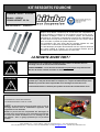
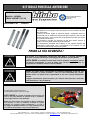
KIT MOLLE FORCELLA ANTERIORE
CODICE :MH42 K=0.85
Modello : HONDA
CB600 HORNET ’02-‘04
AGGIORNATO AL : 27/04/2011
Bitubo è un marchio che dal ’75 riscuote successi nel mondo delle
competizioni e una sempre crescente fiducia nei suoi prodotti da parte
dei motociclisti.
L’utilizzo di acciaio legato di massima qualità, i trattamenti termici e
superficiali che ne esaltano la risposta alle alte frequenze, oltre che alla
durata nel tempo, sono le basi sulle quali abbiamo puntato per offrirVi
un prodotto da campioni.
Le sensazioni di guida che otterrete sin dai primi istanti saranno le
migliori conferme sulla qualità dei prodotti Bitubo.
La caratteristica principale del Kit Bitubo è una migliore risposta alle
sollecitazioni della guida, che vi permetteranno di condurre con più
sicurezza ed efficacia la Vostra motocicletta.
PRIMA LA TUA SICUREZZA !
La forcella è un importante componente della Moto e in questo manuale è
descritto il metodo corretto per il montaggio del Kit Molle Forcella Bitubo.
NOTA BENE: Il Kit Molle Forcella deve essere installato unicamente presso
un’officina specializzata; in caso di dubbi sulle istruzioni qui contenute, Vi
preghiamo di contattare subito un tecnico Bitubo.
Bitubo non potrà essere responsabile di modifiche apportate al Kit che non
sono contenute in questo manuale, e che non sono autorizzate per iscritto.
Bitubo inoltre non potrà essere responsabile di una non corretta installazione
del Kit.
Leggete attentamente questo manuale, per ottenere dalla Forcella il massimo
delle prestazioni e del rendimento.
N. DI MATRICOLA/SERIAL N.
DA INDICARE IN CASO DI RECLAMO/
TO BE MENTIONATED IN CASE OF CLAME
NOTA BENE: la garanzia del Kit Molle Forcella cessa nel
caso in cui venga montato in maniera errata, o modificato,
senza l’approvazione scritta da Bitubo.
Bitubo non potrà essere responsabile di danni al prodotto o
alle persone, in caso le istruzioni contenute in questo
manuale non vengano seguite esattamente, o in caso il
montaggio del Kit Molle Forcella non venga effettuato presso
una officina specializzata, e da personale qualificato.
C.D.A. BITUBO s.n.c. – Via A. Volta,24 – 35037 Z.I. Teolo (PD) ITALY – Tel. (+39) 049-990.34.75
Fax (+39) 049-990.34.47 – Cod Fisc. e Part. IVA 02007650282 – E-mail: [email protected] - Internet: http://www.bitubo.com
ISTRUZIONI DI MONTAGGIO
1.
Posizionare la moto su di un cavalletto centrale, oppure utilizzare i cavalletti posteriori da forcellone.
2.
Inserire sotto la piastra inferiore il cavalletto specifico per il sollevamento dell’avantreno.
3.
Togliere eventuali cupolino e/o carena anteriore e tutti i componenti necessari per poter intervenire sulle piastre
superiore e inferiore: per questi smontaggi seguire scrupolosamente le istruzioni riportate sui manuali tecnici della
moto.
4.
Togliere ruota anteriore e parafango.
5.
Procedere con lo sfilamento di un gambale dalla piastra forcella: allentare le viti della piastra superiore, scaricare
eventualmente la pressione dell’aria (tappo con valvola ad aria), quindi svitare il tappo superiore della forcella, infine le
viti della piastra inferiore .
6.
Togliere il gambale dalla piastra forcella.
7.
Ripetere la procedura dei punti 5 e 6 con l’altro gambale.
OPERAZIONI DA ESEGUIRE SU ENTRAMBI I GAMBALI:
1.
Togliere il tappo superiore:
a) Nel caso di forcella convenzionale: estrarre eventuali distanziali, estrarre la molla e rovesciare il gambale per
svuotarlo dall’olio presente.
b) Nel caso di forcella rovesciata: utilizzando l’apposita attrezzatura svitare il dado di bloccaggio dell’asta pompante
sul tappo forcella; sfilare eventuali distanziali, estrarre la molla e rovesciare il gambale per svuotarlo dall’olio.
2.
Eseguire alcune compressioni ed estensioni del gambale per eliminare l’olio residuo (nel caso di forcella rovesciata:
eseguire il movimento sull’asta pompante per svuotare la cartuccia).
3.
Versare apposito cleaner e ripetere l’operazione di svuotamento (lavaggio).
4.
Dopo aver lasciato sgocciolare il gambale per alcuni minuti, posizionare il gambale alla massima compressione e
versare olio SAE 20 fino a 120mm dal bordo superiore; controllare attentamente la misura perché determinante nella
progressività finale della forcella.
5.
Effettuare alcune compressioni ed estensioni dell’asta pompante, e lasciare alcuni minuti il gambale a riposo tutto
esteso per far uscire eventuali residui di aria.
6.
Controllare nuovamente il livello dell’olio ed eseguire eventuale rabbocco fino alla misura indicata.
NOTA: il livello e il tipo di olio sono importanti parametri per la taratura della progressione di risposta della forcella; la
misura consigliata è pertanto un valore medio per l’utilizzo sportivo con pilota da 75 kg. Il distanziale molla in alluminio
è fornito per applicare un precarico molla maggiore, per piloti più pesanti.
Contattare un centro tecnico di assistenza Bitubo per un utilizzo diverso o personalizzazione ulteriore della taratura.
NOTA: in caso il Kit Molle sia montato in associazione al nostro Kit Valvole K-FORK, il livello dell’olio e il tipo di olio da
utilizzare saranno quelli indicati nelle istruzioni del Kit K-FORK.
7.
Inserire la molla nel gambale. Nel caso di molla progressiva, posizionarla con le spire ravvicinate verso l’alto.
8.
Inserire i distanziali molla forniti nel Kit Molle Bitubo.
9.
Avvitare il tappo superiore;
10. Nelle forcelle munite di valvola per immissione di aria consigliamo di non inserire pressione.
11. Rimontare i gambali nelle piastre forcella e serrare di seguito:
• viti piastra inferiore (controllare coppia di serraggio sul manuale di officina della moto).
• tappi forcella.
• viti piastra superiore (controllare coppia di serraggio sul manuale di officina della moto).
12. Rimontare parafango, ruota, pinze freno, seguendo scrupolosamente le procedure indicate nei manuali di officina della
moto.
13. Rimontare la carenatura e tutti gli accessori previsti per completare l’operazione.
BITUBO RACCOMANDA:
C.D.A. BITUBO s.n.c. – Via A. Volta,24 – 35037 Z.I. Teolo (PD) ITALY – Tel. (+39) 049-990.34.75
Fax (+39) 049-990.34.47 – Cod Fisc. e Part. IVA 02007650282 – E-mail: [email protected] - Internet: http://www.bitubo.com
FRONT FORK SPRING KIT
CODE :MH42 K=0.85
Model : HONDA
CB600 HORNET ’02-‘04
UPDATED ON : 27/04/2011
Bitubo is a brand that has been winning praise in the competition world
and an increasingly growing trust in its products by motorcyclists since
1975.
The use of alloy steel of the highest quality, heat and surface
treatments that stress its response to high frequencies, apart from its
life, are the bases we aimed at to offer you a product worthy of
champions.
The driving sensations you will feel right from the start shall be the best
confirmation of the quality of the Bitubo products.
The main characteristic of the Bitubo Kit is an improved response to the
driving stress so that you will drive your motorcycle more effectively and
safely.
FIRST YOUR SAFETY !
The fork is an important component of the motorcycle and this manual
describes the correct way to assemble the Bitubo Fork Spring Kit.
NOTE: The Fork Spring Kit must be installed exclusively in a specialised
workshop; if you have any doubts regarding these instructions, please contact
a Bitubo engineer straight away.
Bitubo cannot be held responsible for any modifications to the Kit not
described in this handbook or not authorised in writing. Moreover Bitubo
cannot be held responsible for the incorrect installation of the Kit.
Read this handbook carefully so that you can get the best performance and
efficiency out of the Fork.
NOTE: The warranty for the Fork Spring Kit will be
invalidated by incorrect installation or modifications
carried out without Bitubo’s written authorisation.
Bitubo cannot be held responsible for any damages to
the product or injuries to people if the instructions of
this handbook are not followed to the letter or if the
Fork Spring Kit is not fitted in a specialised workshop
or by qualified personnel.
C.D.A. BITUBO s.n.c. – Via A. Volta,24 – 35037 Z.I. Teolo (PD) ITALY – Tel. (+39) 049-990.34.75
Fax (+39) 049-990.34.47 – Cod Fisc. e Part. IVA 02007650282 – E-mail: [email protected] - Internet: http://www.bitubo.com
ASSEMBLY INSTRUCTIONS
1. Position the motorcycle on a central stand or use the rear chassis stands.
2. Insert the special stand to raise the forecarriage underneath the lower plate.
3. Remove any front cowl and/or front underbody and all the necessary components to get to the top and bottom
plates: for all dismantling instructions see the technical handbooks of the motorcycle.
4. Remove the front wheel and the mudguard.
5. Proceed by slipping off one fork leg from the fork plate: unscrew the top plate bolts, release the air pressure
(plug with air valve) if necessary, then unscrew the fork top plug and finally the screws of the bottom plate.
6. Remove the fork leg from the fork plate.
7. Repeat the procedure of steps 5 and 6 for the other fork leg.
OPERATIONS TO CARRY OUT ON BOTH FORK LEGS:
1. Remove the top plug:
a) With a conventional fork: remove any spacers together with the spring and turn the fork leg upside down to
let the oil come out.
b) With an upside-down fork: undo the pumping rod locking nut on the fork plug using the special tools;
remove any spacers together with the spring and turn the fork leg upside down to let the oil come out.
2. Compress and extend the fork leg a few times to expel any oil left (in an upside-down fork: empty the cartridge by
moving the pumping rod).
3. Pour the special cleaner and repeat emptying (flushing).
4. After letting the fork leg drain for a few minutes, compress it to the end of its run and pour oil SAE 20 up to
120mm from the top; check the level carefully because it is vital for the fork graduality.
5. Compress and extend the pumping rod a few times and leave the fork leg totally extended for a few minutes to get
rid of any air pockets.
6. Check the oil level again and top up as required to the level shown.
NOTE: The level and type of oil are important parameters in setting the fork gradual response; the recommended level
is therefore an average value to use at sport’s level with a driver weighing 75kg. Alluminium spacer for more preload.
Contact a Bitubo service centre for different uses or further customisation of the setting.
NOTE: If the Spring Kit is fitted together with our K-FORK valve Kit, the level and type of oil to use are as stated in the
K-FORK Kit instructions.
7. Insert the spring into the fork leg. If the spring is of the gradual type, position it with its turns close together facing
upwards.
8. Insert the spring spacers supplied with the Bitubo Spring Kit.
9. With a conventional fork, screw the top plug in; with an upside-down fork, using the special tools, compress the
spring and screw the cartridge pumping rod into the top plug, then screw the plug onto the fork leg.
10. We recommend you do not put pressure onto forks fitted with an air intake valve.
11.
•
•
•
Fit the fork legs into the fork plates and tighten in the following order:
lower plate screws (check the tightening torque on the service manual for the motorcycle);
fork plugs;
top plate screws (check the tightening torque on the service manual for the motorcycle).
Refit the mudguard, wheel and brake calipers following scrupulously the procedure described in the service manual
for the motorcycle.
13. Refit the underbody and all the accessories and complete the operation.
12.
BITUBO RECOMMENDS:
C.D.A. BITUBO s.n.c. – Via A. Volta,24 – 35037 Z.I. Teolo (PD) ITALY – Tel. (+39) 049-990.34.75
Fax (+39) 049-990.34.47 – Cod Fisc. e Part. IVA 02007650282 – E-mail: [email protected] - Internet: http://www.bitubo.com
KIT RESSORTS FOURCHE
CODICE :MH42 K=0.85
Modèle : HONDA
CB600 HORNET ’02-‘04
MIS AU JOUR LE : 27/04/2011
Depuis 1975, Bitubo a beaucoup de succès dans les compétitions et
chez les motards, la confiance en nos produits s’accroît de jour en jour.
L’utilisation d’alliages d’acier de la meilleure qualité, les traitements
thermiques et de surface qui améliorent la réponse aux sollicitations, et
la durée dans le temps sont le bases de travail que nous avons choisie
pour vous offrir un produit de qualité supérieure.
Les sensations que vous aurez dès les premiers instants de votre
conduite vous confirmeront la qualité des produit Bitubo.
La caractéristique principale des Kits Bitubo est une réponse améliorée
aux chocs pendant la conduite, qui vous permettra d’obtenir plus de
sécurité et une meilleure performance de votre moto.
LA SECURITE AVANT TOUT !
La fourche est un composant fondamental de la moto. Ce manuel décrit le
montage correct du kit ressorts fourche Bitubo.
AVERTISSEMENT : ce kit doit être assemblé uniquement par un professionnel.
En cas de doute, veuillez consulter un technicien Bitubo.
Bitubo ne pourra être tenu responsable de toute modification apportée au
produit qui n’est pas décrite dans ce manuel, ou n’a pas été autorisée par écrit.
Bitubo ne pourra être tenu responsable d’un montage incorrect de ce kit.
Lisez attentivement ce manuel pour profiter au mieux du rendement de ce kit.
N. DE SERIE/SERIAL N.
A INDIQUER EN CAS DE RECLAMATION/
TO BE MENTIONATED IN CASE OF CLAME
NOTE : la garantie du kit ressorts fourche cesse en cas de
montage incorrect et/ou de modifications apportées sans
approbation écrite de Bitubo.
Bitubo ne pourra être tenu responsable des dommages au
produit et/ou aux personnes si les instructions de montage
n’ont pas été suivies exactement, ou si le montage n’a pas
été effectué dans un garage spécialisé par un personnel
qualifié.
C.D.A. BITUBO s.n.c. – Via A. Volta,24 – 35037 Z.I. Teolo (PD) ITALY – Tel. (+39) 049-990.34.75
Fax (+39) 049-990.34.47 – Cod Fisc. e Part. IVA 02007650282 – E-mail: [email protected] - Internet: http://www.bitubo.com
INSTRUCTIONS DE MONTAGE
1. Positionnez la moto sur une béquille centrale ou sur une béquille d’atelier.
2. Délestez l’avant de la moto avec une béquille avant (prise sous la colonne de direction).
3.
Retirez, si présents, la bulle de carénage et/ou le carénage et toutes les parties qui empêchent de travailler sur les tés
de fourche : pour cette opération, veuillez consulter le manuel d’entretien du véhicule.
4.
Retirez les étriers de frein, la roue avant et le garde-boue.
5.
Retirez les fourreaux des tés de fourche : dévissez les vis du té supérieur, déchargez la pression de l’air (soupape
d’aire), dévissez le bouchon de la fourche et les vis du té inférieur.
6.
Retirez le fourreau des tés.
7.
Répétez l’opération des points n° 5 et 6 pour l’ autre fourreau.
OPERATIONS A EXECUTER SUR LES TUBES DE FOURCHE :
8. Dévissez le bouchon supérieur :
a. Fourche conventionnelle : retirez les entretoises, le ressort et renversez le tube pour vider l’huile.
b.
Fourche inversée : dévissez l’écrou qui se trouve sur le bouchon ; retirez les entretoises, le ressort et renversez le
tube pour vider l’huile.
9.
10.
Comprimez le tube pour vider l’huile restante (fourche inversée : agissez sur le piston).
Utilisez du cleaner et répétez l’opération purge (nettoyage).
11. Laissez égoutter le tube pour quelques minutes, puis comprimez le tube et versez de l’huile SAE 20 jusqu’à 120mm
du bord supérieur ; contrôlez attentivement le niveau parce qu’il est très important pour la fluidité de la fourche.
12. Comprimez et détendez le piston, puis détendez le tube et laissez-le détendu pour quelques minutes pour éliminer l’air
dans le tube.
13. Contrôlez le niveau de l’huile et si cela est nécessaire, remplissez jusqu’au niveau indiqué.
NOTE : le niveau et le type d’huile sont importants pour le calibrage de la fourche ; la valeur conseillée est une valeur
moyenne pour l’usage sportif par un pilote de 75 kg.
Contactez un centre d’assistance Bitubo pour un usage différent ou pour personnaliser le calibrage.
NOTE : si le Kit ressort est monté en combinaison avec notre Kit K-FORK, appliquez le niveau et le type d’huile
indiqués dans les instructions du Kit K-FORK.
14. Positionnez le ressort dans le tube. Si vous utilisez un ressort à pas progressif, les spires les plus resserrées doivent
être tournées vers haut.
15. Positionnez la rondelle et l’entretoise fournies dans le kit.
16. Fourche conventionnelle : vissez le bouchon ; Fourche inversée, comprimez le ressort et vissez le piston de la
cartouche sur le bouchon, puis vissez le bouchon sur le tube de fourche.
17. Fourches avec soupape d’aire : ne pas appliquer de pression.
18. Remontez les tubes sur les tés et serrez :
• Les vis du té inférieur (couple de serrage indiqué dans le manuel d’entretien du véhicule).
• Les bouchons.
• Les vis du té supérieur (couple de serrage indiqué dans le manuel d’entretien du véhicule).
19. Remontez le garde-boue, la roue, les étriers de frein, comme indiqué dans le manuel d’entretien du véhicule.
20. Remontez le carénage et les autres parties pour compléter l’opération.
C.D.A. BITUBO s.n.c. – Via A. Volta,24 – 35037 Z.I. Teolo (PD) ITALY – Tel. (+39) 049-990.34.75
Fax (+39) 049-990.34.47 – Cod Fisc. e Part. IVA 02007650282 – E-mail: [email protected] - Internet: http://www.bitubo.com