1
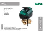
Montage
Anschluss
Wartungsarbeiten
Systembeispiel
CS-ZV
Handbuch für den
Fachhandwerker
de
Handbuch
en
Manual
fr
Manuel
es
Manual
11204823
*11204823*
it
Manuale
Vielen Dank für den Kauf dieses Gerätes.
Bitte lesen Sie diese Anleitung sorgfältig durch, um die Leistungsfähigkeit dieses Gerätes optimal
nutzen zu können. Bitte bewahren Sie diese Anleitung sorgfältig auf.
nl
Handboek
CS-ZV
Seite 2/48
Sicherheitshinweise
Inhalt
Bitte beachten Sie diese Sicherheitshinweise genau, um
Gefahren und Schäden für Menschen und Sachwerte auszuschließen.
1
2
3
4
5
6
7
Vorschriften
Beachten Sie bei allen Arbeiten die nationalen und regionalen gesetzlichen Vorschriften, Normen, Richtlinien und
Sicherheitsbestimmungen.
Handbetrieb ....................................................... 3
Übersicht ............................................................ 4
Einbaulage........................................................... 4
Installationshinweise .......................................... 5
Ansteuerung 2-Punkt ........................................ 5
Montage .............................................................. 6
Anwendungsbeispiel .......................................... 6
Angaben zum Gerät
Symbolerklärung
Bestimmungsgemäße Verwendung
WARNUNG!
Das CS-ZV ist für Schaltprozesse innerhalb einer Solaroder Heizungsanlage unter Berücksichtigung der in dieser
Anleitung angegebenen technischen Daten bestimmt.
Die bestimmungswidrige Verwendung führt zum Ausschluss
jeglicher Haftungsansprüche.
CE-Konformitätserklärung
Das Produkt entspricht den relevanten Richtlinien
und ist daher mit der CE-Kennzeichnung versehen. Die Konformitätserklärung kann beim Hersteller angefordert werden.
Hinweis
Starke elektromagnetische Felder können die
Funktion des Reglers beeinträchtigen.
Î Sicherstellen, dass Regler und Anlage keinen
starken elektromagnetischen Strahlungsquellen ausgesetzt sind.
Warnhinweise sind mit einem Warndreieck
gekennzeichnet!
ÎEs wird angegeben, wie die Gefahr
vermieden werden kann!
Signalwörter kennzeichnen die Schwere der Gefahr, die
auftritt, wenn sie nicht vermieden wird.
• WARNUNG bedeutet, dass Personenschäden, unter
Umständen auch lebensgefährliche Verletzungen auftreten
können
• ACHTUNG bedeutet, dass Sachschäden auftreten
können
Hinweis
Hinweise sind mit einem Informationssymbol gekennzeichnet.
Î Textabschnitte, die mit einem Pfeil gekennzeichnet sind,
fordern zu einer Handlung auf.
Irrtum und technische Änderungen vorbehalten.
Zielgruppe
© 20130830_11204823_Citrin_CS-ZV_.mon6S.indd
Diese Anleitung richtet sich ausschließlich an autorisierte
Fachkräfte.
Elektroarbeiten dürfen nur von Elektrofachkräften durchgeführt werden.
Die erstmalige Inbetriebnahme hat durch den Ersteller der
Anlage oder einen von ihm benannten Fachkundigen zu erfolgen.
Entsorgung
• Verpackungsmaterial des Gerätes umweltgerecht entsorgen.
• Altgeräte müssen durch eine autorisierte Stelle umweltgerecht entsorgt werden. Auf Wunsch nehmen wir Ihre
bei uns gekauften Altgeräte zurück und garantieren für
eine umweltgerechte Entsorgung.
CitrinSolar GmbH Energie- u. Umwelttechnik • Böhmerwaldstr. 32 • D-85368 Moosburg • Tel.:+49 (0) 8761/33400 • Fax: +49 (0) 8761/334040
CS-ZV
Technische Daten
Antrieb
Nennspannung: 220 ... 240 V~ (50 ... 60 Hz)
Antriebsmotor: Synchronmotor
Belastung der Endlageschalter:
5(1)A, 220 ... 240 V~ (50 ... 60 Hz)
Nennleistung: 7,5 VA max.
Isolationklasse: II Schutzisoliert
Antriebsschutzart: IP44
Stellzeit: 30s / 90°
Betriebsart: geöffnet - geschlossen
Umgebungstempertur: 0° C ...+50° C
Drehmoment: 6 Nm (max. 8 Nm)
Elektrischer Anschluss: Steuerleitung 4 x 0,5 mm²
Ventil
Temperatur des Mediums: 0° C ... +120° C
Nenndruck: PN 15 (max. PN 16)
Ventilanschluss: Mit beidseitigem Innengewinde
Durchfluss: Voller Durchgang, entsprechend der NW.
Ventilkörper: Pressmessing (CuZn40Pb2)
Ventilanschluss: Messing (CuZn40Pb2)
Ventilspindel: Messing (CuZn40Pb2)
Ventilkugel: Messing, hartverchromt
Kugeldichtung: PTFE-Ring-Teflondichtung
Spindeldichtung:
1 x O-Ring EPDM, 1 x O-Ring Viton und 1 x O-Ring PTFE
Dichtung-Spindel zu Ventil:
1 x O-Ring EPDM, durch eine weitere Dichtung wird die
axiale Pressung zwischen Ventilspindel und Nut kompensiert.
Seite 3/48
CS-ZV
Einsatzbereich:
Der elektromotorisch angetriebene CS-ZV / 2-WegeKugelhahn wird dem internationalen Fertigungsstandard
entsprechend gefertigt und bietet universelle Einsatzmöglichkeiten in Heizungs-, Warmwasser-, Solar- und Bewässerungssystemen. Dem Anwender werden vielfältige Einsatzmöglichkeiten im Bereich der Energieverteilung geboten.
Leistungsmerkmale:
Kompakte Ausführung, gefällige Form und modernes Design,
schutzisoliertes Antriebsgehäuse. Einfache manuelle Handverstellung für Inbetriebnahme oder Notbetrieb. Elektrischer universeller Anschluss, durch integriertes Relais
(230 V~, 50 Hz.).
Die Ansteuerung erfolgt durch einen Zweipunktkontakt. Der
Endschalter-Signalausgang in Ventilstellung kann für Steuerzwecke verwendet werden (max 1 A). Position der Ventilkugel Durchflussrichtung durch Indikatorstellung (weiß)
erkennbar. Schnelles wechseln der Antriebseinheit ohne
Ausbau des Ventils möglich. Keine Durchflussreduzierung
voller Durchgang, entsprechend der jeweiligen Ausführung
von DN15-DN32.
1
Handbetrieb
Für Kontroll- und Servicearbeiten kann die Betriebsart des
Ventils manuell eintgestellt werden.
Im Handbetrieb wird der Stellantrieb nicht vom Steuersignal beeinflusst, der Einstellhebel ist stufenlos verstellbar.
Um die Betriebsart des Ventils umzustellen, wie folgt vorgehen:
Î Antrieb zum Ventil drücken.
Î Den Antrieb in die gewünschte Position bringen (Indikator auf-zu).
Der Antrieb muss beim Loslassen hörbar einrasten.
Für den Automatikbetrieb den Antrieb wieder in Grundposition bringen.
Hinweis
Nach Abschluss der Kontroll- und Servicearbeiten
muss die Betriebsart wieder auf AUTO gestellt werden. Ein normaler Regelbetrieb ist im Handbetrieb
nicht möglich.
CitrinSolar GmbH Energie- u. Umwelttechnik • Böhmerwaldstr. 32 • D-85368 Moosburg • Tel.:+49 (0) 8761/33400 • Fax: +49 (0) 8761/334040
CS-ZV
2
Seite 4/48
Übersicht
78
C
H
A
B
125
D
G
DN
A
B
C
D
H
PN
KV
USA
CV
½"
15
139
121,5
17,5
63
79
16
17
22
¾"
20
144
124,5
19,5
57
85
16
41
50
1"
25
153
129,5
23,5
68
93
16
68
84
1 ¼"
32
163
134,5
28,5
81
103
16
123
153
25
32
/4"
1"
20
11
1/2
"
15
"
DN
3/4
∆p
1/2", 3/4", 1", 1 1/4"
3
Einbaulage
Das Ventil ist beliebig einbaubar, jedoch nicht mit dem Antrieb nach unten. Zur Bedienung
der manuellen Handverstellung +/- 90°, beim Elektroanschluss eine Kabelschlaufe von ca.
25 cm vorsehen. Um für Servicearbeiten genügend Arbeitsraum zu erhalten, einen Wandbzw. Geräteabstand von mind. 100 mm einhalten.
wrong
CitrinSolar GmbH Energie- u. Umwelttechnik • Böhmerwaldstr. 32 • D-85368 Moosburg • Tel.:+49 (0) 8761/33400 • Fax: +49 (0) 8761/334040
CS-ZV
4
Seite 5/48
Installationshinweise
Die Montage des Ventils ist nach den einschlägigen Regeln
der Technik vorzunehmen. Dichtmittel- bzw. Hanfreste oder
dergleichen, dürfen nicht in den Ventilkörper gelangen. Um
eine Blockierung der Ventilkugel zu vermeiden, sind folgende
Hinweise zu beachten und jegliche Löt- oder Schweißarbeiten in direkter Umgebung des Ventils zu vermeiden.
5
Ansteuerung 2-Punkt
WARNUNG!
Ader
Schwarz
Braun
Blau
Rot
Hinweis
Um die optimale Betriebssicherheit zu erreichen,
wird empfohlen die Anlage vorher zu spülen und
einen entsprechenden Schmutzfänger (0,65 μm)
vor jedem Ventil einzubauen.
Elektrischer Schlag!
Die rote Endlageschalter-Ader ist abisoliert
und führt bei geöffneter Ventilstellung Spannung!
Wenn der Antrieb nicht über den angeschlossenen Regler abgesichert ist, besteht
die Gefahr eines elektrischen Schlags!
Î Betriebsspannung mit externer
Vorsicherung absichern!
Regler
Schaltkontakt
Steuerphase
Liegt der Schaltkontakt L (230 V~) vom Regler an,
öffnet das Ventil.
Liegt kein Schaltkontakt vom Regler an, wird das
Ventil wieder in die Ausgangslage zurückgestellt
(geschlossen).
Dauerphase L (230 V~)
Neutralleiter N (230V~)
Endschalter-Ausgangssignal (230 V~)
Hinweis
Zur Bedienung der manuellen Handverstellung
+/- 90°, beim Elektroanschluss eine Kabelschlaufe
von ca. 25 cm vorsehen.
CitrinSolar GmbH Energie- u. Umwelttechnik • Böhmerwaldstr. 32 • D-85368 Moosburg • Tel.:+49 (0) 8761/33400 • Fax: +49 (0) 8761/334040
CS-ZV
6
Montage
Die Antriebseinheit ist mit dem Kugelhahn durch eine Sechskantmutter fixiert (5). Dadurch kann die Motoreinheit auf
einfache Weise vom Kugelhahn getrennt und die O-Ringe
gewartet werden, um ein hohes Maß an Betriebssicherheit
zu garantieren.
Zur Demontage folgendermaßen vorgehen:
Î Beide Schrauben (8) lösen.
Î Den Antrieb (1) vom Ventilkörper (7) abnehmen.
Î Die Fixierscheibe (2) abnehmen.
Î Die Feder (3) entnehmen und den Indikator (4) abnehmen.
Î Die Sechskantmutter (5) lösen.
Î Den Gehäuseträger vom Ventilkörper (7) lösen.
Î Die Stopfbuchsenverschraubung (9) lösen.
Î Die Spindel (10) aus dem Ventil ziehen.
Die O-Ringe sind nun zugänglich und können gewartet
oder ausgetauscht werden.
Î Anschließend das Ventil in umgekehrter Reihenfolge
wieder zusammenbauen.
O-Ringe:
(12) 14 x 1.78 - EPDM
(13) 12 x 10 x 1 - PTFE
(14) 8.73 x 1.78 - EPDM
(15) 8.73 x 1.78 - Viton
7
Seite 6/48
Bei geöffnetem Ventil steht die Indikator-Anzeige auf weiß,
bzw auf rot. Aufbau und Konstruktion der Kugeldichtungen
erlauben einen sanften Schließvorgang mit einem sehr
niedrigen Drehmoment. Dies gewährleistet eine exakte
Positionierung und Dichtheit, sowie eine hohe Betriebssicherheit des Kugelventils.
Anwendungsbeispiel
Solarsystem mit 1 Kollektor
und 2 Speicher
CitrinSolar GmbH Energie- u. Umwelttechnik • Böhmerwaldstr. 32 • D-85368 Moosburg • Tel.:+49 (0) 8761/33400 • Fax: +49 (0) 8761/334040
CS-ZV
Seite 7/48
Notizen
CitrinSolar GmbH Energie- u. Umwelttechnik • Böhmerwaldstr. 32 • D-85368 Moosburg • Tel.:+49 (0) 8761/33400 • Fax: +49 (0) 8761/334040
Ihr Fachhändler:
© Sämtliche Inhalte dieses Dokuments sind urheberrechtlich geschützt.
CitrinSolar GmbH Energie- u. Umwelttechnik • Böhmerwaldstr. 32 • D-85368 Moosburg • Tel.:+49 (0) 8761/33400 • Fax: +49 (0) 8761/334040
Manual for the
specialised craftsman
CS-ZV
Mounting
Connection
Maintenance
Example
en
Manual
Thank you for buying this product.
Please read this manual carefully to get the best performance from this unit.
Please keep this manual carefully.
CS-ZV
Page 10/48
Safety advice
Contents
Please pay attention to the following safety advice in order
to avoid danger and damage to people and property.
1
2
3
4
5
6
7
Instructions
Attention must be paid to the valid local standards, regulations and directives!
Manual mode .................................................... 11
Overview ........................................................... 12
Installation position ......................................... 12
Installation instructions ................................... 13
On-off control ................................................... 13
Mounting ........................................................... 14
Example ............................................................ 14
Information about the product
Proper usage
The CS-ZV is designed for switching processes in a solar
or heating systems in compliance with the technical data
specified in this manual.
Improper use excludes all liability claims.
CE-Declaration of conformity
The product complies with the relevant directives and is therefore labelled with the CE mark.
The Declaration of Conformity is available upon
request, please contact the manufacturer.
Note
Strong electromagnetic fields can impair the function of the controller.
Î Make sure the controller as well as the system
are not exposed to strong electromagnetic
fields.
Description of symbols
WARNING!
Warnings are indicated with a warning
triangle!
ÎThey contain information on how
to avoid the danger described.
Signal words describe the danger that may occur, when it
is not avoided.
• WARNING means that injury, possibly life-threatening
injury, can occur.
• ATTENTION means that damage to the appliance can
occur.
Note
Notes are indicated with an information symbol.
Î Arrows indicate instruction steps that should be carried out.
Subject to technical change. Errors excepted.
Target group
These instructions are exclusively addressed to authorised
skilled personnel.
Only qualified electricians should carry out electrical works.
Initial installation must be effected by qualified personnel
named by the manufacturer.
Disposal
• Dispose of the packaging in an environmentally sound
manner.
• Dispose of old appliances in an environmentally sound
manner. Upon request we will take back your old
appliances bought from us and guarantee an environmentally sound disposal of the devices.
CitrinSolar GmbH Energie- u. Umwelttechnik • Böhmerwaldstr. 32 • D-85368 Moosburg • Tel.:+49 (0) 8761/33400 • Fax: +49 (0) 8761/334040
CS-ZV
Technical Data
Drive
Rated voltage: 230 V~, 50 Hz
Motor: synchronous motor
Load of limit switch: 5(1)A, 250V~, 50 Hz
Rated power: 7,5 VA max.
Insulation class: II insulated
Protection type: IP44
Actuation time: 30s / 90°
Mode: open - closed
Ambient temperature: 0° C ...+50° C
Torque 6 Nm (max. 8 Nm)
Electrical connection: control line 4 x 0,5 mm²
Valve
Temperature of the medium: 0° C ... +120° C
Rated pressure: PN 15 (max. PN 16)
Valve connection: IT on both sides of the valve connection
Flow: full flow, corresponding to the nominal width NW.
Valve body: pressed brass (CuZn40Pb2)
Valve connection: brass (CuZn40Pb2)
Valve spindle: brass (CuZn40Pb2)
Valve ball: brass, hard chromium-plated
Ball seal: PTFE ring-Teflon sealing
Spindle seal: 1 x O-ring EPDM, 1 x O-ring Viton and
1 x O-ring PTFE
Sealing spindle to vale: 1 x O-ring EPDM, the axial pressing between valve spindle and slot can be compensated for
by means of another sealing
Page 11/48
CS-ZV
Area of application:
The 2-port motor-driven ball valve CS-ZV is produced according to international standards and offers universal fields
of application in heating-, warm water-, solar- and irrigation
systems. A large number of application possibilities in the
field of energy distribution is provided to the user.
Characteristics:
Compact size, modern design, insulated actuator-housing.
Simple manual control for commissioning or emergency
operation. Electrical universal connection through integrated
relay (220 ... 240 V~).
The valve is supplied as normally open, but can easily be
changed to normally closed by pushing and turning the
valve head through 90° relative to the body as shown in
the diagram.
The valve changes position when the black wire is energised.
The brown must be connected to a permanent live.The red
wire is a control signal output that can be used for control
purposes (max.1 A). The position of the ball valve is visible
with the white indicator flag. The actuator can be quickly
replaced without disassembly.The DN20 and DN25 versions
offer full bore flow.
1
Manual mode
For control and service work, the operating mode of the
valve can be manually adjusted.
In manual mode, the control signal does not affect the actuator, the adjustment lever is continuously adjustable.
In order to change the operating mode of the valve, proceed as follows:
Î Push the actuator towards the valve.
Î Adjust the actuator to the desired position.
The actuator must latch audibly when released.
For automatic operation, adjust the actuator back into the
basic position.
Note
Always adjust the operating mode back to AUTO
when the control and service work is completed.
Normal operation is not possible in manual mode.
CitrinSolar GmbH Energie- u. Umwelttechnik • Böhmerwaldstr. 32 • D-85368 Moosburg • Tel.:+49 (0) 8761/33400 • Fax: +49 (0) 8761/334040
CS-ZV
2
Page 12/48
Overview
78
C
H
A
B
125
D
G
DN
A
B
C
D
H
PN
KV
USA
CV
½"
15
139
121,5
17,5
63
79
16
17
22
¾"
20
144
124,5
19,5
57
85
16
41
50
1"
25
153
129,5
23,5
68
93
16
68
84
1 ¼"
32
163
134,5
28,5
81
103
16
123
153
25
32
/4"
1"
20
11
1/2
"
15
3/4
DN
"
∆p
1/2", 3/4", 1", 1 1/4"
3
Installation position
The valve can be mounted in any position (see figure below), but should not face downwards. A cable loop of about 25 cm is required for +/- 90° manual operation. In order to
have enough space to carry out maintenance work, a distance of at least 100 mm should
be kept between the valve and the walls or other devices.
wrong
CitrinSolar GmbH Energie- u. Umwelttechnik • Böhmerwaldstr. 32 • D-85368 Moosburg • Tel.:+49 (0) 8761/33400 • Fax: +49 (0) 8761/334040
CS-ZV
4
Page 13/48
Installation instructions
Important note
In order to attain the maximum operating safety and reliability, it is recommended to flush the
system and to insert an appropriate strainer (0,65
μm) in front of each valve.
The installation of the valve must be carried out in accordance with the approved technical regulations. Ensure excess sealing material, tape etc does not enter the valve body.
In order to avoid blocking of the valve ball, pay attention
to the following advice and avoid all soldering, or welding
processes close to the valve.
flow direction
1 - ball valves
5
2 - strainer
~ 0,65 μm
3 - EMV 110.. Compact- ball valve
On-off control
WARNING!
Electric shock!
The red limit switch lead is not insulated
and carries voltage when the valve is in the
open position!
If the actuator is not fused through the
controller connected, there is a risk of electric shock!
ÎFuse the operating voltage with an
external pre-fuse of max. 2A!
black
control cont.
blue
brown
Ader
Black
Brown
Blue
Red
Control line
If the auxiliary phase L (230 V~) is energised, the
valve opens.
If there is no control signal, the valve is put back to
its initial position (closed).
permanent live L (230 V~)
neutral line N (230V~)
limit switch output signal
red
Note
A cable loop of about 25 cm is required for +/- 90°
manual operation.
CitrinSolar GmbH Energie- u. Umwelttechnik • Böhmerwaldstr. 32 • D-85368 Moosburg • Tel.:+49 (0) 8761/33400 • Fax: +49 (0) 8761/334040
CS-ZV
6
Page 14/48
Mounting
The actuator is attached to the ball valve by means of a
hexagon nut (5).Therefore, the actuator can be easily removed from the ball valve. The O-rings can be maintained. This
guarantees high operating safety and reliability.
In order to disassemble the unit, proceed as follows:
When the valve is in the open position, the indicator is
on white or on red respectively. The structure of the ball
sealings allows the valve to close smoothly and with a very
low torque.This allows precise positioning and leak tightness
and guarantees high operating safety and reliability of the
ball valve.
Î Unscrew both screws (8).
Î Remove the actuator (1) from the valve body (7).
Î Remove the washer (2).
Î Remove the spring (3) and the indicator (4).
Î Unscrew the hexagonal nut (5).
Î Remove the housing support from the valve body (7).
Î Unscrew the gland screw connection (9).
Î Remove the spindle (10) from the valve.
Now the o-rings are accessible for maintenance or replacement.
Î To reassemble the valve, carry out the steps in reverse
order.
Please carry out assembly in reverse order.
o-rings:
(12) 14 x 1.78 - EPDM
(13) 12 x 10 x 1 - PTFE
(14) 8.73 x 1.78 - EPDM
(15) 8.73 x 1.78 - Viton
7
Example
Solar thermal system with
1 collector and 2 stores
CitrinSolar GmbH Energie- u. Umwelttechnik • Böhmerwaldstr. 32 • D-85368 Moosburg • Tel.:+49 (0) 8761/33400 • Fax: +49 (0) 8761/334040
CS-ZV
Page 15/48
Notes
CitrinSolar GmbH Energie- u. Umwelttechnik • Böhmerwaldstr. 32 • D-85368 Moosburg • Tel.:+49 (0) 8761/33400 • Fax: +49 (0) 8761/334040
Distributed by:
© All contents of this document are protected by copyright.
CitrinSolar GmbH Energie- u. Umwelttechnik • Böhmerwaldstr. 32 • D-85368 Moosburg • Tel.:+49 (0) 8761/33400 • Fax: +49 (0) 8761/334040
Manuel pour
le technicien habilité
CS-ZV
Montage
Branchement
Entretien
Exemple d’application
fr
Manuel
Merci d'avoir acheté ce produit.
Veuillez lire le présent mode d’emploi attentivement afin de pouvoir utiliser l’appareil de manière optimale.Veuillez conserver ce mode d’emploi.
CS-ZV
Pagina 18/48
Recommandations de sécurité
Sommaire
Veuillez lire attentivement les recommandations de sécurité suivantes afin d’éviter tout dommage aux personnes
et aux biens.
1
2
3
4
5
6
7
Instructions
Lors des travaux, veuillez respecter les normes, réglementations et directives en vigueur!
Mode manuel .................................................... 19
Vue d´ensemble ................................................ 20
Position de montage ........................................ 20
Indications pour l‘installation ......................... 21
Commande tout ou rien ................................ 21
Montage ............................................................ 22
Exemple d‘application ..................................... 22
Informations concernant l’appareil
Utilisation conforme
La vanne d’inversion CS-ZV s’utilise dans le domaine du
chauffage solaire et du chauffage conventionnel en tenant
compte des données techniques énoncées dans le présent
mode d’emploi. Toute utilisation non conforme aux prescriptions du fabricant exonérera celui-ci de toute responsabilité.
Déclaration de conformité CE
Le marquage „CE“ est apposé sur le produit, celuici étant conforme aux dispositions communautaires prévoyant son apposition. La déclaration de
conformité est disponible auprès du fabricant sur
demande.
Note
Des champs électromagnétiques trop élevés peuvent perturber le fonctionnement de l’appareil.
Î Veillez à ne pas exposer ce dernier à des champs
électromagnétiques trop élevés.
Explication des symboles
AVERTISSEMENT !
Les avertissements de sécurité sont
précédés d’un triangle de signalisation !
ÎIl est indiqué comment éviter
le danger !
Les avertissements caractérisent la gravité du danger qui
survient si celui-ci n’est pas évité.
• Avertissement indique que de graves dommages corporels, voire même un danger de mort peuvent survenir.
• Attention indique que des dommages aux biens peuvent survenir.
Note
Toute information importante communiquée à
l’utilisateur est précédée de ce symbole.
Î Les instructions sont précédées d’une flèche
Sous réserve d’erreurs et de modifications techniques
Groupe cible
Ce manuel d’instructions vise exclusivement les techniciens habilités.
Toute opération électrotechnique doit être effectuée par
un technicien en électrotechnique.
La première mise en service de l’appareil doit être effectuée par le fabricant ou par un technicien désigné par celui-ci.
Traitement des déchets
• Veuillez recycler l’emballage de l’appareil.
• Les appareils en fin de vie doivent être déposés auprès
d’une déchèterie ou d’une collecte spéciale de déchets
d’équipements électriques et électroniques. Sur demande, nous reprenons les appareils usagés que vous
avez achetés chez nous et garantissons ainsi une élimination respectueuse de l’environnement.
CitrinSolar GmbH Energie- u. Umwelttechnik • Böhmerwaldstr. 32 • D-85368 Moosburg • Tel.:+49 (0) 8761/33400 • Fax: +49 (0) 8761/334040
CS-ZV
Caractéristiques techniques
Servomoteur
Tension nominale : 220 ... 240 V~ (50 ... 60 Hz)
Moteur: synchrone
Charge des interrupteur de fin de course :
5(1)A, 220 ... 240 V~ (50 ... 60 Hz)
Puissance nominale : maximum 7,5 VA
Degré de protection : II
Type de protection moteur : IP44
Durée de réglage / angle de rotation : 30s / 90°
Mode de fonctionnement : ouvert - fermé
Température ambiante : 0° C ...+50° C
Couple : 6 Nm (maximum 8 Nm)
Branchement électrique : câble 4 x 0,5 mm²
Vanne
Température du caloporteur : 0° C ... +120° C
Pression nominale : PN 15 (maximum PN 16)
Raccords : raccords filetés femelles des deux côtés
Débit: ouverture totale non réglable de la vanne, conformément au DN.
Vanne : en laiton forgé (CuZn40Pb2)
Raccords : en laiton (CuZn40Pb2)
Tige de la vanne : en laiton (CuZn40Pb2)
Bille de la vanne : en laiton chromé dur
Étanchéité de la bille :
assurée par 1 bague PTFE et 1 joint Teflon
Étanchéité de la tige :
assurée par 1 bague EPDM, 1 bague Viton et 1 bague
PTFE
Joint de la tige côté vanne : EPDM, un joint supplémentaire compense la compression axiale entre la tige de la
vanne et sa rainure.
Pagina 19/48
CS-ZV
Champs d’application:
La vanne à bille motorisée à 2 voies CS-ZV a été fabriquée
conformément au niveau international de production. Elle
s’utilise dans les systèmes de chauffage solaire et conventionnel et dans les systèmes de production d’eau chaude et
d’irrigation. Elle offre de nombreuses possibilités d’utilisation
dans le domaine de la distribution d’énergie.
Propriétés:
Modèle compact, forme séduisante et design moderne; moteur
doté d’un boîtier protecteur isolant. Réglage manuel pour la
mise en marche ou l’arrêt d’urgence. Branchement électrique
universel à travers un relais intégré (230 V~, 50 Hz.).
La vanne fonctionne sur la base d’une commande tout ou
rien. Le signal de sortie de l’interrupteur de fin de course
peut être utilisé pour manoeuvrer la vanne (maximum
1A). L’indicateur blanc indique la position de la tige de la
vanne (le sens du débit). Possibilité de changer le moteur
rapidement sans démonter la vanne. Il n’est pas possible de
régler le degré d’ouverture de la vanne, conformément aux
versions correspondantes DN15-DN32.
1
Mode manuel
Pour effectuer des opérations de contrôle ou de maintenance, il est possible de régler manuellement la position de
réglage de la vanne.
En mode manuel, le signal de contrôle du régulateur n'agit
pas sur le moteur de la vanne, le levier de réglage est réglable sans paliers.
Afin de modifier le mode de fonctionnement de la vanne,
procédez comme suit :
Î Pressez le servomoteur contre la vanne.
Î Tournez la vanne sur la position souhaitée (indicateur
ouvert-fermé).
Lorsque vous relâcher le servomoteur, celui-ci doit faire un
bruit en s'emboîtant.
Pour régler la vanne en mode automatique, remettez-la sur
la position initiale.
Note
Après toute opération de maintenance ou de contrôle,
rétablissez le mode automatique AUTO. Autrement
l'appareil ne fonctionnera pas correctement.
CitrinSolar GmbH Energie- u. Umwelttechnik • Böhmerwaldstr. 32 • D-85368 Moosburg • Tel.:+49 (0) 8761/33400 • Fax: +49 (0) 8761/334040
CS-ZV
2
Pagina 20/48
Vue d´ensemble
78
C
H
A
B
125
D
G
DN
A
B
C
D
H
PN
KV
USA
CV
½"
15
139
121,5
17,5
63
79
16
17
22
¾"
20
144
124,5
19,5
57
85
16
41
50
1"
25
153
129,5
23,5
68
93
16
68
84
1 ¼"
32
163
134,5
28,5
81
103
16
123
153
25
32
/4"
1"
20
11
1/2
"
15
3/4
DN
"
∆p
1/2", 3/4", 1", 1 1/4"
3
Position de montage
La vanne peut se monter dans n’importe quelle position, sauf avec le moteur vers le bas.
Lors du branchement électrique de la vanne, laissez 25 cm de câble en plus afin de pouvoir
régler celle-ci manuellement +/- 90°. Prévoyez également un écart d’au moins 100 mm entre
le mur et l’appareil afin d’avoir assez de place pour effectuer des opérations d’entretien.
Non
CitrinSolar GmbH Energie- u. Umwelttechnik • Böhmerwaldstr. 32 • D-85368 Moosburg • Tel.:+49 (0) 8761/33400 • Fax: +49 (0) 8761/334040
CS-ZV
4
Pagina 21/48
Indications pour l’installation
Le montage de la vanne doit s’effectuer conformément
aux règles techniques locales. Veiller à ce qu’aucun reste
de chanvre, de produit d’étanchéité etc... ne pénètre dans
la vanne. Afin d’empêcher la vanne de se bloquer, lire les
indications suivantes et éviter toute opération de soudage
près de celle-ci.
Note
Afin d‘assurer le bon fonctionnement de la vanne,
il est conseillé de rincer l‘installation solaire et
d‘installaler un séparateur d‘impuretés (0,65 μm)
devant toutes les vannes de votre installation
avant d‘installer la CS-ZV.
sens du débit entrée
1 - vannes à bille pour l‘entretien
5
2 - séparateur d‘impuretés ~ 0,65 μm
3 - EMV 110.. vanne à bille compacte
Commande tout ou rien
AVERTISSEMENT ! Choc électrique !
Le conducteur rouge de l'interrupteur de fin de course est dénudé et
sous tension lorsque la vanne est en
position d'ouverture !
Lorsque le moteur n'est pas protégé à travers le régulateur, des chocs
électriques sont susceptibles de se
produire.
Î Protégez la vanne avec un
fusible externe !
noir
phase de
commande
bleu
marron
rouge
Fil
noir
Phase de commande
Lorsque le contact commutateur L (230V~) reçoit
un signal de commande du régulateur, la vanne
s'ouvre.
À défaut de signal de commande, la vanne se remet
en position de départ (vanne fermée).
marron
Phase continue L (230V~)
bleu
Conducteur neutre N (230V~)
rouge
Signal de sortie de l‘interrupteur de fin de course
(230V~)
Note
Lors du branchement électrique de la vanne, prévoyez 25 cm de câble en plus pour pouvoir régler
celle-ci manuellement +/- 90°.
CitrinSolar GmbH Energie- u. Umwelttechnik • Böhmerwaldstr. 32 • D-85368 Moosburg • Tel.:+49 (0) 8761/33400 • Fax: +49 (0) 8761/334040
CS-ZV
6
Montage
Le servomoteur est fixé à la vanne à bille avec un écrou
hexagonal (5), ce qui permet de le détacher facilement de
celle-ci pour effectuer des opérations d’entretien, contrôler
les bagues et assurer, par là-même, le bon fonctionnement
de l’appareil.
Le démontage de la CS-ZV est très simple et doit s’effectuer
de la manière suivante :
Î Desserrez les deux vis (8) et détachez le servomoteur (1)
de la vanne (7)
Î Retirez la rondelle de fixation (2)
Î Retirez le ressort (3) et soulevez l’indicateur (4)
Î Dévissez l’écrou hexagonal (5) et détachez le support
de la vanne (7)
Î Dévissez le presse-étoupe (9)
Î Retirez la tige de la vanne (10)
Î À présent, les bagues sont accessibles et peuvent être
contrôlées ou remplacées si nécessaire.
Bagues:
(12) 14 x 1.78 - EPDM
(13) 12 x 10 x 1 - PTFE
(14) 8.73 x 1.78 - EPDM
(15) 8.73 x 1.78 - Viton
7
Pagina 22/48
Lorsque la vanne est en position d’ouverture, l’indicateur
est sur „blanc“ ou sur „rouge“. Les propriétés physiques
des joints de la bille garantissent un processus de fermeture
lent et un couple moteur assez bas et assurent, de ce fait,
une parfaite étanchéité, un positionnement ultraprécis ainsi
qu’un fonctionnement optimal de ladite bille.
Exemple d’application
Système solaire à 1 capteur et 2
réservoirs
CitrinSolar GmbH Energie- u. Umwelttechnik • Böhmerwaldstr. 32 • D-85368 Moosburg • Tel.:+49 (0) 8761/33400 • Fax: +49 (0) 8761/334040
CS-ZV
Pagina 23/48
Notes
CitrinSolar GmbH Energie- u. Umwelttechnik • Böhmerwaldstr. 32 • D-85368 Moosburg • Tel.:+49 (0) 8761/33400 • Fax: +49 (0) 8761/334040
Votre distributeur:
© Tous les contenus du présent document sont couverts par des droits d'auteur
CitrinSolar GmbH Energie- u. Umwelttechnik • Böhmerwaldstr. 32 • D-85368 Moosburg • Tel.:+49 (0) 8761/33400 • Fax: +49 (0) 8761/334040
Manual para
técnicos habilitados
CS-ZV
Montaje
Conexión
Mantenimiento
Ejemplo de instalación
es
Manual
Gracias por comprar este producto.
Por favor, lea este manual de instrucciones atentamente antes de utilizar el producto.
Conserve el manual de instrucciones cuidadosamente.
CS-ZV
Página 26/48
Recomendaciones para la seguridad
Indice
Por favor, observe las siguientes medidas de seguridad para
evitar daños a personas y a bienes materiales.
Antes de intervenir en el aparato, observe las normas nacionales y regionales, directivas y recomendaciones para la
seguridad vigentes.
1
2
3
4
5
6
7
Indicaciones sobre el producto
Explicación de los símbolos
Uso correcto
¡AVISO!
Normas
La válvula CS-ZV está indicada para realizar operaciones de
conmutación en los sistemas de calefacción solar y convencional y se debe utilizar teniendo en cuenta los datos técnicos enunciados en el presente manual de instrucciones.
La empresa declina cualquier responsabilidad respecto a la
utilización incorrecta del producto.
Declaración de conformidad CE
El producto CS-ZV lleva el certificado CE, pues
cumple con las disposiciones de las directivas
europeas relevantes. La declaración de conformidad está disponible bajo pedido.
Nota
Los campos electromagnéticos muy fuertes pueden alterar el funcionamiento de la válvula.
Î Asegúrese por lo tanto de que ésta no esté
expuesta a fuertes campos electromagnéticos.
Ajuste manual .................................................. 27
Visión de conjunto ........................................... 28
Posición de instalación..................................... 28
Indicaciones para la instalación ...................... 29
Ajuste de dos posiciones ................................. 29
Montaje ............................................................. 30
Ejemplo de instalación .................................... 30
¡Las señales de peligro tienen forma triangular!
Î ¡Indican al usuario cómo evitar peligros!
Se advierte al usuario del grave peligro al que se expone, en
caso de no respeto de las consignas indicadas.
• „AVISO“ significa que pueden surgir daños graves a
personas o, incluso, que hay peligro de muerte
• „ATENCIÓN“ significa que pueden surgir daños
materiales
Î Los párrafos precedidos por una flecha obligan al usuario a intervenir en la válvula.
Nota
Este símbolo indica INFORMACIÓN para los
usuarios.
Errores y modificaciones técnicas reservados.
A quien se dirige este manual de instrucciones
Este manual de instrucciones se dirige exclusivamente a
técnicos habilitados.
Cualquier trabajo electrotécnico deberá ser efectuado exclusivamente por un técnico autorizado.
La primera puesta en marcha de la válvula deberá ser realizada por el fabricante de la instalación o por su personal
técnico.
Tratamiento de los residuos
• Realice un tratamiento ecológico del embalaje del producto
• Los equipos, una vez finalizada su vida útil, deben ser
entregados a un punto de regogida para ser tratados
ecológicamente. Retiramos los equipos usados garantizándole un tratamiento ecológico de los residuos bajo
pedido
CitrinSolar GmbH Energie- u. Umwelttechnik • Böhmerwaldstr. 32 • D-85368 Moosburg • Tel.:+49 (0) 8761/33400 • Fax: +49 (0) 8761/334040
CS-ZV
Datos técnicos
Mando eléctrico
Tensión nominal: 220 ... 240 V~ (50 ... 60 Hz)
Motor sincrónico
Carga de los interruptores finales:
5(1)A, 220 ... 240 V~ (50 ... 60 Hz)
Potencia nominal: máximo 7,5 VA
Aislamiento protector: II
Protección: IP44
Tiempo de ajuste: 30s / 90° (ángulo de rotación)
Modo de funcionamiento: abierto - cerrado
Tempertura ambiente: 0° C ...+50° C
Par motor: 6 Nm (máximo 8 Nm)
Conexión eléctrica: cable de 4 x 0,5 mm²
Válvula
Temperatura del fluido: 0° C ... +120° C
Presión nominal: PN 15 (máximo PN 16)
Empalme: dos roscas interiores
Caudal: paso máximo, según el diámetro nominal.
Cuerpo: de latón prensado (CuZn40Pb2)
Empalme: de latón (CuZn40Pb2)
Eje de la válvula: de latón (CuZn40Pb2)
Esfera de la válvula: de latón cromado duro
Junta de la esfera: anilla PTFE-Teflon
Junta del eje:
1 anilla EPDM, 1 anilla Viton und 1 anilla PTFE
Junta del eje lado válvula: 1 anilla EPDM, una segunda
junta compensa la compresión axial entre el eje y la ranura
de la válvula.
Página 27/48
CS-ZV
Ámbito de utilización:
La válvula de paso CS-ZV se utiliza para retener o
dejar circular líquidos en los sistemas de energía
solar y en aquellos equipados con bombas de calor,
teniendo en cuenta los datos técnicos enunciados en
este manual de instrucciones.
Prestaciones:
modelo compacto, forma elegante y diseño moderno; caja
protectora. Ajuste manual muy simple para la puesta en
marcha y la modalidad de emergencia. Conexión eléctrica
universal mediante un relé integrado (230 V~, 50 Hz.).
La válvula tiene dos posiciones de ajuste. La señal de salida
del interruptor de fin de carrera se puede utilizar para manejar la bomba (máximo 1 A). El indicador blanco indica la
posición de ajuste de la válvula (sentido del flujo). El motor
se puede reemplazar de forma muy rápida sin desmontar
la válvula. No se puede reducir el caudal, conforme a las
versiones DN15-DN32.
1
Ajuste manual
Para realizar operaciones de control o mantenimiento, la
posición de funcionamiento de la válvula se puede ajustar
manualmente.
En modo de funcionamiento manual, la señal de control del
termostato no afecta al motor de la válvula, la palanca de
cambio de sentido se puede ajustar sin escalones.
Para modificar el modo de funcionamiento de la válvula,
proceda como se indica a continuación:
Î Presione el motor sobre la válvula.
Î Ajuste el motor en la posición deseada (indicador de
posición abierta-cerrada).
Cuando suelte el motor, éste deberá hacer ruido al encajar
en la válvula.
Para ajustar la válvula en modo automático, ponga el motor
en la posición inicial.
Nota
Vuelva siempre a ajustar el modo de funcionamiento a Auto cuando se hayan terminado las tareas de
control y mantenimiento. De lo contrario, no será
posible el funcionamiento normal.
CitrinSolar GmbH Energie- u. Umwelttechnik • Böhmerwaldstr. 32 • D-85368 Moosburg • Tel.:+49 (0) 8761/33400 • Fax: +49 (0) 8761/334040
CS-ZV
2
Página 28/48
Visión de conjunto
78
C
H
A
B
125
D
G
DN
A
B
C
D
H
PN
KV
USA
CV
½"
15
139
121,5
17,5
63
79
16
17
22
¾"
20
144
124,5
19,5
57
85
16
41
50
1"
25
153
129,5
23,5
68
93
16
68
84
1 ¼"
32
163
134,5
28,5
81
103
16
123
153
25
32
/4"
1"
20
11
1/2
"
15
3/4
DN
"
∆p
1/2", 3/4", 1", 1 1/4"
3
Posición de instalación
La válvula se puede instalar en cualquier posición, menos con el motor hacia abajo. Al enchufarla a la red eléctrica, procure dejar 25 cm de cable adicionales para facilitar su manejo
+/- 90°. Prevea también un espacio mínimo de 100 mm entre la CS-ZV y la pared para
poder intervenir en la misma.
No
CitrinSolar GmbH Energie- u. Umwelttechnik • Böhmerwaldstr. 32 • D-85368 Moosburg • Tel.:+49 (0) 8761/33400 • Fax: +49 (0) 8761/334040
CS-ZV
4
Página 29/48
Indicaciones para la instalación
El montaje de la válvula se debe realizar conforme a las
normas técnicas vigentes. Asegúrese de que ningún resto
de impermeabilizante o residuo de cáñamo etc. entre en
la válvula. Para evitar que la esfera de la válvula se bloquee,
observe la siguiente información y no efectue operaciones
de soldeo cerca de la válvula.
Nota
Para garantizarle la mayor seguridad operativa a
la válvula, lave el sistema de energía solar y coloque un filtro adecuado (0,65 μm) delante de la
misma antes de instalarla.
sentido del flujoentrada
válvulas de mantenimiento
5
válvula esférica compacta
filtro
Ajuste de dos posiciones
¡AVISO!
¡Descargas eléctricas!
¡El conductor rojo del interruptor de fin de
carrera no está aislado y está bajo tensión
cuando está activada la válvula! Si el motor
no está protegido mediante el regulador conectado, ¡puede que se produzcan descargas
eléctricas!
ΡProteja la válvula con un fusible
externo para limitar la corriente!
Contacto
conmutador termostato
negro
azul
marrón
Conductor
Negro
Fase de control
Si el contacto de conmutación L (230 V~) recibe
corriente a través del termostato, la válvula se
abre.
En caso contrario, la válvula se vuelve a poner en
la posición inicial (cerrada).
Marrón
Fase continua L (230 V~)
Azul
Conductor neutro N (230V~)
Rojo
Borne del interruptor de fin de carrera (230 V~)
rojo
Nota
Cuando enchufe la válvula a la red eléctrica, procure dejar 25 cm de cable adicionales para facilitar el manejo manual +/- 90° de la misma.
CitrinSolar GmbH Energie- u. Umwelttechnik • Böhmerwaldstr. 32 • D-85368 Moosburg • Tel.:+49 (0) 8761/33400 • Fax: +49 (0) 8761/334040
CS-ZV
6
Montaje
El motor eléctrico está fijado a la válvula con una tuerca
hexagonal (5), lo cual permite extraerlo facilmente para
realizar operaciones de mantenimiento y controlar las anillas
de estanqueidad, garantizándole así el mejor funcionamiento.
Es muy sencillo desmontar la válvula; el desmontaje debe
realizarse como se indica a continuación:
Î Desatornille ambos tornillos (8) y separe la unidad motriz (1) de la válvula (7)
Î Desmonte la arandela de fijación (2)
Î Desmonte el muelle (3) y extraiga el indicador (4)
Î Desenrosque la tuerca hexagonal (5) y desmonte el soporte de la válvula (7)
Î Desenrosque el prensaestopas (9)
Î Saque el vástago de la válvula (10)
Î Ahora puede acceder a las anillas y controlarlas o cambiarlas
Anillas de estanqueidad:
(12) 14 x 1.78 - EPDM
(13) 12 x 10 x 1 - PTFE
(14) 8.73 x 1.78 - EPDM
(15) 8.73 x 1.78 - Viton
7
Página 30/48
Cuando la válvula está en posición de apertura, el indicador
indica el color blanco o rojo. Las características de fabricación de las juntas de la esfera garantizan un cierre lento de la
válvula y un par del motor muy bajo, proporcionándole así a
la esfera la máxima estanqueidad, el exacto posicionamiento
y la mayor eficacia.
Ejemplo de instalación
Sistema de energía solar con 1
captador y 2 acumuladores
CitrinSolar GmbH Energie- u. Umwelttechnik • Böhmerwaldstr. 32 • D-85368 Moosburg • Tel.:+49 (0) 8761/33400 • Fax: +49 (0) 8761/334040
CS-ZV
Página 31/48
Notas
CitrinSolar GmbH Energie- u. Umwelttechnik • Böhmerwaldstr. 32 • D-85368 Moosburg • Tel.:+49 (0) 8761/33400 • Fax: +49 (0) 8761/334040
Su distribuidor:
© El contenido del presente documento está protegido por derechos de autor.
CitrinSolar GmbH Energie- u. Umwelttechnik • Böhmerwaldstr. 32 • D-85368 Moosburg • Tel.:+49 (0) 8761/33400 • Fax: +49 (0) 8761/334040
Manuale per il
tecnico abilitato
CS-ZV
Montaggio
Allacciamento
Manutenzione
Esempio applicativo
it
Manuale
Grazie di aver acquistato questo apparecchio.
Leggere attentamente il presente manuale per poter usufruire in maniera ottima della
funzionalità di questo apparecchio. Conservare il manuale per riferimenti futuri.
CS-ZV
Pagina 34/48
Avvertenze per la sicurezza
Indice
Osservare queste avvertenze per la sicurezza per escludere pericoli e danni a persone e materiali.
1
2
3
4
Prescrizioni
Osservare le prescrizioni, norme, direttive e disposizioni
di sicurezza nazionali e regionali in vigore durante tutti i
lavori.
5
6
7
Comando manuale .......................................... 35
Panoramica ....................................................... 36
Montaggio ......................................................... 36
Indicazioni per l‘installazione della ...................
valvola ............................................................... 37
Comando a due posizioni ................................ 37
Montaggio ......................................................... 38
Esempio applicativo ......................................... 38
Indicazioni relative all'apparecchio
Uso conforme allo scopo previsto
Spiegazione dei simboli impiegati
La valvola CS-ZV è progettata per realizzare operazioni
di commutazione negli impianti di riscaldamento solare e
convenzionale in considerazione dei dati tecnici enunciati
nel presente manuale.
L'uso non conforme allo scopo previsto comporta l'esclusione di qualsiasi garanzia.
AVVERTENZA!
Dichiarazione di conformità CE
Il prodotto è conforme alle disposizioni delle
direttive europee rilevanti ed è perciò garantito dalla marcatura CE. La dichiarazione di conformità è fornibile su richiesta.
Nota
Forti campi elettromagnetici possono compromettere il funzionamento dell'apparecchio.
Î Assicurarsi che l'apparecchio non sia sottoposto a forti campi elettromagnetici.
Destinatari
Le avvertenze sono contrassegnate da un
triangolo di avvertimento.
ÎIndicano come evitare il pericolo
incombente!
Le parole impiegate per avvertire l‘utenza indicano la gravità del pericolo incombente in caso di mancata osservanza
delle relative indicazioni.
• AVVERTENZA significa che possono verificarsi danni
a persone e lesioni mortali.
• ATTENZIONE significa che possono verificarsi danni
materiali.
Nota
Le note sono contrassegnate da un simbolo di
informazione.
Î I paragrafi contrassegnati da una freccia costringono
l‘utente ad agire.
Salvo errori e modifiche tecniche.
Queste istruzioni si rivolgono esclusivamente a personale
qualificato e autorizzato.
I lavori elettrici devono essere eseguiti esclusivamente da
un elettricista specializzato.
La prima messa in funzione deve essere eseguita dal costruttore dell'impianto o da una persona qualificata da lui
autorizzata.
Smaltimento
• Smaltire l‘imballaggio dell‘impianto in modo ecocompatibile.
• Gli impianti vecchi devono essere smaltiti secondo
metodi ecologicamente corretti presso una piattaforma ecologica abilitata. Riprendiamo gli impianti usati
comprati da su richiesta e garantiamo uno smaltimento
ecocompatibile.
CitrinSolar GmbH Energie- u. Umwelttechnik • Böhmerwaldstr. 32 • D-85368 Moosburg • Tel.:+49 (0) 8761/33400 • Fax: +49 (0) 8761/334040
CS-ZV
Caratteristiche tecniche
Motore
Tensione nominale: 220 ... 240 V~ (50 ... 60 Hz)
Motore: sincrono
Carico degli interruttori di fine corsa: 5(1)A, 220 ...
240 V~ (50 ... 60 Hz)
Potenza nominale: massimo 7,5 VA
Grado di protezione: II
Protezione del motore: IP44
Tempo di manovra: 30s / 90°
Modalità di funzionamento: aperto - chiuso
Temperatura ambiente: 0° C ...+50° C
Coppia: 6 Nm (massimo 8 Nm)
Allacciamento elettrico:
cavo di alimentazione 4 x 0,5 mm²
Valvola
Temperatura del fluido: 0° C ... +120° C
Pressione nominale: PN 15 (massimo PN 16)
Attacco della valvola: filettatura F in entrambi i lati
Portata: passaggio totale in base al DN
Corpo della valvola: in ottone pressato (CuZn40Pb2)
Attacco della valvola: in ottone (CuZn40Pb2)
Asta della valvola: in ottone (CuZn40Pb2)
Sfera della valvola: in ottone, cromato duro
Guarnizione della sfera: anello PTFE e Teflon
Guarnizione dell‘asta:
1 x anello EPDM, 1 x anello Viton e 1 x anello PTFE
Guarnizione dell‘asta lato valvola: 1 x anello EPDM, la
pressione assiale tra l‘asta della valvola e la scanalatura viene
compensata da una guarnizione addizionale.
Pagina 35/48
CS-ZV
Campo di applicazione:
La valvola diritta CS-ZV è progettata per consentire o impedire il passaggio dei fluidi negli impianti solari e in quelli
equipaggiati con pompe di calore, attenendosi ai dati tecnici
enunciati nel presente manuale.
Particolarità costruttive:
Modello compatto, forma piacevole e disegno moderno;
involucro protettivo per il motore. Facile manovra manuale
per la messa in moto o la modalità di emergenza. Allacciamento elettrico universale tramite un relè integrato
(230 V~, 50 Hz.).
Il comando della valvola avviene mediante un contatto tutto
o niente. Il segnale di uscita dell‘interruttore di fine corsa
può essere impiegato per azionare la pompa (massimo 1
A). La posizione della sfera della valvola è riconoscibile
dall‘indicatore bianco. Il motore può essere sostituito facilmente senza che sia necessario smontare la valvola. Il flusso
del fluido non può essere ridotto quando vi è passaggio
totale, in base alle versioni DN15-DN32.
1
Comando manuale
Per eseguire operazioni di controllo e servizio, la posizione
di funzionamento della valvola può essere regolata manualmente.
Nel modo manuale, il segnale di controllo emesso dalla
centralina non agisce sul motore della valvola, l’asta di comando può essere ruotata senza gradini.
Per modificare il modo operativo della valvola, procedere
come segue:
Î Premere il servocomando contro la valvola.
Î Regolare il servocomando nella posizione desiderata.
Una volta rilasciato il servocomando si deve udire lo scatto.
Per il modo automatico, rimettere il servocomando nella
posizione iniziale.
Nota
Una volta concluse le operazioni di controllo e servizio, il modo operativo deve essere impostato di
nuovo su "Auto". Altrimenti non è possibile il funzionamento normale.
CitrinSolar GmbH Energie- u. Umwelttechnik • Böhmerwaldstr. 32 • D-85368 Moosburg • Tel.:+49 (0) 8761/33400 • Fax: +49 (0) 8761/334040
CS-ZV
2
Pagina 36/48
Panoramica
78
C
H
A
B
125
D
G
DN
A
B
C
D
H
PN
KV
1/2"
3/4"
1"
1 1/4"
15
20
25
32
139
144
153
163
121,5
124,5
129,5
134,5
17,5
19,5
23,5
28,5
63
57
68
81
79
85
93
103
16
16
16
16
17
41
68
123
20
25
32
1"
11
/4"
1/2
"
15
"
DN
3/4
∆p
USA
CV
22
50
84
153
1/2", 3/4", 1", 1 1/4"
3
Montaggio
La valvola può essere montata in qualsiasi posizione, tranne che con il servocomando rovesciato. Durante il collegamento elettrico è opportuno lasciare 25 cm di cavo per facilitare il
comando manuale +/- 90° della valvola.Tra l‘apparecchio e la parete, inoltre, devono essere
lasciati almeno 100 mm per avere spazio sufficiente per eseguire interventi di manutenzione.
posizione
sbagliata
CitrinSolar GmbH Energie- u. Umwelttechnik • Böhmerwaldstr. 32 • D-85368 Moosburg • Tel.:+49 (0) 8761/33400 • Fax: +49 (0) 8761/334040
CS-ZV
4
Pagina 37/48
Indicazioni per l‘installazione della
valvola
Il montaggio della valvola deve essere effettuato in base alle
norme tecniche vigenti. Assicurarsi che eventuali residui di
sostanze impermeabilizzanti, resti di canapa ecc. non penetrino nel corpo della valvola. Per prevenire il bloccaggio
della sfera della valvola, osservare le seguenti indicazioni ed
evitare le operazioni di saldatura in vicinanza della valvola.
senso del fluido ingresso
1 - valvola a sfera per la
manutenzione
5
2 - defangatore ~ 0,65 μm
Nota
Per garantire la massima sicurezza operativa della
valvola, è consigliato di lavare l‘impianto solare e
di montare un adeguato defangatore (0,65 μm)
davanti ad ogni valvola.
3 - EMV 110.. valvola a sfera compatta
Comando a due posizioni
AVVERTENZA!
Scossa elettrica!
Il filo rosso dell'interruttore di fine corsa
non è protetto da una guaina ed è sotto
tensione! Se il servocomando non è protetto tramite la centralina collegata, possono avvenire scosse elettriche!
ÎProteggere la valvola limitando la
corrente con un fusibile esterno!
nero
azzurro
marrone
Filo
Nero
Contatto di
commutazione centralina
Fase di comando
Se il contatto di commutazione L (230 V~) riceve
corrente dalla centralina, la valvola si apre.
Nel caso contrario, la valvola si rimette nella posizione iniziale (chiusa).
Marrone
Fase continua L (230 V~)
Azzurro
Conduttore neutro N (230V~)
Rosso
Uscita dell‘interruttore di fine corsa (230 V~)
rosso
Nota
Durante il collegamento elettrico è opportuno
lasciare 25 cm di cavo per facilitare il comando
manuale +/- 90° della valvola.
CitrinSolar GmbH Energie- u. Umwelttechnik • Böhmerwaldstr. 32 • D-85368 Moosburg • Tel.:+49 (0) 8761/33400 • Fax: +49 (0) 8761/334040
CS-ZV
6
Montaggio
Il motore è accopiato alla valvola a sfera con un dado
esagonale (5) ed è perciò facilmente separabile dal corpo
di quest‘ultima per operazioni di manutenzione. Tale particolarità costruttiva consente inoltre di manutenzionare
semplicemente gli anelli di tenuta per garantire un elevato
livello di sicurezza nel funzionamento della valvola.
Lo smontaggio della valvola è molto semplice e deve essere
effettuato nel seguente ordine:
Î Svitare entrambe le viti (8) e togliere il motore (1) dal
corpo della valvola (7).
Î Rimuovere la rondella di fissaggio (2).
Î Rimuovere la molla (3) e sollevare l‘indicatore (4).
Î Svitare il dado esagonale (5) ed estrarre il supporto dalla valvola (7).
Î Svitare il premistoppa (9).
Î Estrarre l‘asta dalla valvola (10).
Î Ora gli anelli sono accessibili e possono essere manutenzionati o sostituiti.
Anelli:
(12) 14 x 1.78 - EPDM
(13) 12 x 10 x 1 - PTFE
(14) 8.73 x 1.78 - EPDM
(15) 8.73 x 1.78 - Viton
7
Pagina 38/48
Quando la valvola è in posizione di apertura, l‘indicatore è
in posizione bianca o rossa. Le caratteristiche costruttive
delle guarnizioni della sfera consentono una lenta chiusura
della valvola ed una bassa coppia motrice, assicurando così
la massima tenuta, l‘esatto posizionamento e la massima
sicurezza nel funzionamento di tale valvola,
Esempio applicativo
impianto solare con 1 collettore e
2 serbatoi
CitrinSolar GmbH Energie- u. Umwelttechnik • Böhmerwaldstr. 32 • D-85368 Moosburg • Tel.:+49 (0) 8761/33400 • Fax: +49 (0) 8761/334040
CS-ZV
Pagina 39/48
Note
CitrinSolar GmbH Energie- u. Umwelttechnik • Böhmerwaldstr. 32 • D-85368 Moosburg • Tel.:+49 (0) 8761/33400 • Fax: +49 (0) 8761/334040
CS-ZV
Pagina 40/48
Rivenditore specializzato:
© Il contenuto del presente documento è coperto da diritto d'autore.
CitrinSolar GmbH Energie- u. Umwelttechnik • Böhmerwaldstr. 32 • D-85368 Moosburg • Tel.:+49 (0) 8761/33400 • Fax: +49 (0) 8761/334040
Montage
Aansluiting
Onderhoudswerkzaamheden
Systeemvoorbeeld
CS-ZV
Handboek voor
de vakman
de
Handbuch
en
Manual
fr
Manuel
es
Manual
it
Manuale
nl
Bedankt voor de aankoop van dit apparaat.
Lees deze handleiding zorgvuldig door om optimaal gebruik te kunnen maken van dit apparaat.
Bewaar deze handleiding zorgvuldig.
Handboek
CS-ZV
Pagina 42/48
Veiligheidsrichtlijnen
Inhoud
Neem deze veiligheidsrichtlijnen precies in acht om gevaren en schade voor mensen en waardevolle voorwerpen
uit te sluiten.
1
2
3
4
5
6
7
Voorschriften
Neem bij allen werkzaamheden de nationale en regionale
wettelijke voorschriften, normen, richtlijnen en veiligheidsbepalingen in acht.
Handbediening ................................................... 3
Overzicht ............................................................ 4
Montagepositie ................................................... 4
Installatieaanwijzingen ...................................... 5
Aansturing 2-punts ............................................ 5
Montage .............................................................. 6
Toepassingsvoorbeeld ........................................ 6
Gegevens van het apparaat
Verklaring van de symbolen
Juist gebruik
WAARSCHUWING!
Het CS-ZV is bedoeld voor schakelprocessen binnen een
zonne-energie- of verwarmingsinstallatie met inachtneming
van de in deze handleiding aangegeven technische gegevens.
Onjuist gebruik leidt tot uitsluiting van alle aansprakelijkheidsclaims.
CE-conformiteitsverklaring
Het product voldoet aan de relevante richtlijnen
en is daarom voorzien van het CE-label. De conformiteitsverklaring kan bij de fabrikant worden
aangevraagd.
Aanwijzing
Sterke elektromagnetische velden kunnen de
werking van de regelaar nadelig beïnvloeden.
Î Let erop dat de regelaar niet aan sterke
elektromagnetische stralingsbronnen wordt
blootgesteld.
Doelgroep
Waarschuwingen worden aangegeven
met een gevarendriehoek!
ÎEr wordt aangegeven hoe het
gevaar kan worden voorkomen!
Signaalwoorden geven de ernst van het gevaar aan dat optreedt als deze niet worden voorkomen.
• WAARSCHUWING betekent dat persoonlijk letsel,
eventueel ook levensgevaarlijk letsel, kan optreden
• LET OP betekent dat materiële schade kan optreden
Aanwijzing
Aanwijzingen worden aangegeven met een informatiesymbool.
Î Tekstgedeeltes die met een pijl worden aangegeven,
vragen om een eigen handeling.
Vergissingen en technische wijzigingen voorbehouden.
© 20130830_11204823_Citrin_CS-ZV_.mon6S.indd
Deze handleiding is uitsluitend bedoeld voor geautoriseerde vakmensen.
Elektrotechnische werkzaamheden mogen alleen uitgevoerd worden door elektromonteurs.
De eerste inbedrijfstelling dient te worden uitgevoerd
worden door de fabrikant van de installatie of door een
door hem benoemd vakkundig persoon.
Afvalverwijdering
• Verpakkingsmateriaal van het apparaat dient milieuvriendelijk te worden weggegooid.
• Oude apparaten dienen door een geautoriseerd
afvalverwijderingsbedrijf milieuvriendelijk te worden
afgevoerd. Desgewenst nemen wij uw bij ons gekochte
oude apparaten terug en garanderen een milieuvriendelijke afvalverwijdering.
CitrinSolar GmbH Energie- u. Umwelttechnik • Böhmerwaldstr. 32 • D-85368 Moosburg • Tel.:+49 (0) 8761/33400 • Fax: +49 (0) 8761/334040
CS-ZV
Technische gegevens
Aandrijving
Nominale spanning: 220 ... 240 V~ (50 ... 60 Hz)
Aandrijfmotor: synchroonmotor
Belasting van de eindschakelaars:
5(1)A, 220 ... 240 V~ (50 ... 60 Hz)
Nominaal vermogen: 7,5 VA max.
Isolatieklasse: II randgeaard
Veiligheidsklasse aandrijving: IP44
Steltijd: 30s / 90°
Bedrijfsmodus: geopend - gesloten
Omgevingstemperatuur: 0° C ...+50° C
Draaimoment: 6 Nm (max. 8 Nm)
Elektrische aansluiting: besturingskabel 4 x 0,5 mm²
Klep
Temperatuur van het medium: 0° C ... +120° C
Nominale druk: PN 15 (max. PN 16)
Klepaansluiting: met tweezijdige binnendraad
Doorstroming: volledige doorgang, conform de NW.
Klephuis: persmessing (CuZn40Pb2)
Klepaansluiting: messing (CuZn40Pb2)
Klepspindel: messing (CuZn40Pb2)
Klepkogel: messing, hard verchroomd
Kogelafdichting: PTFE-ring-teflonafdichting
Spindelafdichting:
1 x O-ring EPDM, 1 x O-ring Viton en 1 x O-ring PTFE
Afdichting van spindel naar klep:
1 x O-ring EPDM, door nog een afdichting wordt de axiale
persing tussen klepspindel en gleuf gecompenseerd.
Pagina 43/48
CS-ZV
Toepassing:
De elektromotorisch aangedreven CS-ZV / 2-weg-kogelkraan wordt conform de internationale productienorm
vervaardigd en biedt universele toepassingsmogelijkheden in
verwarmings-, warmwater-, zonne-energie- en irrigatiesystemen. De gebruiker worden een groot aantal toepassingsmogelijkheden op het gebied van energieverdeling geboden.
Prestatiekenmerken:
Compacte uitvoering, prettige vorm en modern design,
behuizing van de aandrijving is randgeaard. Eenvoudige
handmatige handverstelling voor de inbedrijfstelling of
noodaansturing. Elektrische universele aansluiting, door
geïntegreerd relais (230 V, 50 Hz).
De aansturing vindt plaats door een 2-puntscontact. De
eindschakelaar-signaaluitgang in de klepstand kan voor
besturingsdoeleinden worden gebruikt (max. 1 A). De
positie doorstromingsrichting van de klepkogel is door de
indicatorstand (wit) herkenbaar. Snelle vervanging van de
aandrijfunit is zonder demontage van de klep mogelijk. Geen
doorstromingsreductie, volledige doorgang, overeenkomstig
de betreffende uitvoering van DN15-DN32.
1
Handbediening
Voor controle- en onderhoudswerkzaamheden kan de bedrijfsmodus van de klep handmatig worden ingesteld.
In de handbediening wordt de stelaandrijving niet door het
stuursignaal beïnvloed, de instelhendel is traploos verstelbaar.
Om de bedrijfsmodus van de klep te wijzigen, gaat u als volgt
te werk:
Î Aandrijving tegen de klep duwen.
Î De aandrijving in de gewenste positie brengen (indicator open-dicht).
De aandrijving moet bij het loslaten hoorbaar inhaken.
Voor de automatische modus de aandrijving weer in de
uitgangspositie terugzetten.
Aanwijzing
Na voltooiing van de controle- en onderhoudswerkzaamheden moet de bedrijfsmodus weer op
AUTO worden gezet. Een normale regelstand is in
de handbediening niet mogelijk.
CitrinSolar GmbH Energie- u. Umwelttechnik • Böhmerwaldstr. 32 • D-85368 Moosburg • Tel.:+49 (0) 8761/33400 • Fax: +49 (0) 8761/334040
CS-ZV
2
Pagina 44/48
Overzicht
78
C
H
A
B
125
D
G
DN
A
B
C
D
H
PN
KV
USA
CV
½"
15
139
121,5
17,5
63
79
16
17
22
¾"
20
144
124,5
19,5
57
85
16
41
50
1"
25
153
129,5
23,5
68
93
16
68
84
1 ¼"
32
163
134,5
28,5
81
103
16
123
153
25
32
/4"
1"
20
11
1/2
"
15
3/4
DN
"
∆p
1/2", 3/4", 1", 1 1/4"
3
Montagepositie
De klep kan willekeurig worden ingebouwd, echter niet met de aandrijving naar beneden.
Voor de bediening van de handmatige handverstelling +/- 90° moet bij de elektrische aansluiting een kabellus van ca. 25 cm worden gemaakt. Om voor onderhoudswerkzaamheden
voldoende werkruimte te verkrijgen, moet een afstand tot de muur of het apparaat worden aangehouden van min. 100 mm.
fout
CitrinSolar GmbH Energie- u. Umwelttechnik • Böhmerwaldstr. 32 • D-85368 Moosburg • Tel.:+49 (0) 8761/33400 • Fax: +49 (0) 8761/334040
CS-ZV
4
Pagina 45/48
Installatieaanwijzingen
De montage van de klep dient volgens de relevante voorschriften van de techniek te worden uitgevoerd. Afdichtmiddel- resp. hennepresten en dergelijke mogen niet in het
klephuis terechtkomen. Om een blokkade van de klepkogel
te voorkomen, moeten de volgende aanwijzingen in acht
worden genomen en alle soldeer- of laswerkzaamheden in
de directe omgeving van de klep worden voorkomen.
Aanwijzing
Om een optimale bedrijfsveiligheid te bereiken,
wordt geadviseerd om de installatie vooraf te
spoelen en om een geschikte vuilvanger (0,65 μm)
vóór iedere klep in te bouwen.
Ingang stromingsrichting
1 - Onderhoudskogelkranen
5
3 - EMV 110 Compacte kogelklep
Aansturing 2-punts
WAARSCHUWING!
Draad
Zwart
Bruin
Blauw
Rood
2 - Vuilvanger ~ 0,65 μm
Elektrische schok!
De rode eindschakelaar-draad is afgestript en staat bij geopende klepstand onder spanning!
Als de aandrijving niet via de aangesloten regelaar is afgeschermd, bestaat
de kans op een elektrische schok!
Î Bedrijfsspanning met externe voorzekering afschermen!
Besturingsfase
Als het schakelcontact L (230 V~) van de regelaar
wordt geactiveerd, dan wordt de klep geopend.
Als het schakelcontact van de regelaar niet wordt
geactiveerd, wordt de klep weer teruggezet in de
uitgangspositie (gesloten).
Continufase L (230 V~)
Nulleider N (230V~)
Eindschakelaar-uitgangssignaal (230 V~)
zwart
regelaar
schakelcontact
blauw
bruin
rood
Aanwijzing
Voor de bediening van de handmatige handverstelling +/- 90° moet bij de elektrische aansluiting
een kabellus van ca. 25 cm worden gemaakt.
CitrinSolar GmbH Energie- u. Umwelttechnik • Böhmerwaldstr. 32 • D-85368 Moosburg • Tel.:+49 (0) 8761/33400 • Fax: +49 (0) 8761/334040
CS-ZV
6
Montage
De aandrijfunit is met de kogelkraan door een zeskantmoer
gefixeerd (5). Daardoor kan de motorunit op eenvoudige
wijze worden gescheiden van de kogelkraan en kunnen de
O-ringen worden onderhouden om een grote mate van
bedrijfsveiligheid te garanderen.
Ga voor de demontage als volgt te werk:
Î Draai beide schroeven (8) los.
Î Pak de aandrijving (1) af van het klephuis (7).
Î Verwijder de fixeerschijf (2).
Î Verwijder de veer (3) en de indicator (4).
Î Draai de zeskantmoer (5) los.
Î Scheid de steun van de behuizing van het klephuis (7).
Î Draai de schroefverbinding van de pakkingbus (9) los.
Î Trek de spindel (10) uit de klep.
De O-ringen zijn nu toegankelijke en kunnen worden
onderhouden of vervangen.
Î Monteer de klep vervolgens weer in omgekeerde
volgorde.
O-ringen:
(12) 14 x 1,78 - EPDM
(13) 12 x 10 x 1 - PTFE
(14) 8,73 x 1,78 - EPDM
(15) 8,73 x 1,78 - Viton
7
Pagina 46/48
Bij geopende klep staat de indicator-aanduiding op wit, resp.
op rood. Opbouw en constructie van de kogelafdichtingen
maken een zachte sluiting met een zeer laag draaimoment
mogelijk. Dit garandeert een precieze positionering en dichtheid alsmede een grote bedrijfsveiligheid van de kogelklep.
Toepassingsvoorbeeld
Zonne-energiesysteem met
1 collector en 2 boilers
CitrinSolar GmbH Energie- u. Umwelttechnik • Böhmerwaldstr. 32 • D-85368 Moosburg • Tel.:+49 (0) 8761/33400 • Fax: +49 (0) 8761/334040
CS-ZV
Pagina 47/48
Aantekeningen
CitrinSolar GmbH Energie- u. Umwelttechnik • Böhmerwaldstr. 32 • D-85368 Moosburg • Tel.:+49 (0) 8761/33400 • Fax: +49 (0) 8761/334040
Uw vakhandel:
© De inhoud van dit document is auteursrechtelijk beschermd.
CitrinSolar GmbH Energie- u. Umwelttechnik • Böhmerwaldstr. 32 • D-85368 Moosburg • Tel.:+49 (0) 8761/33400 • Fax: +49 (0) 8761/334040