1
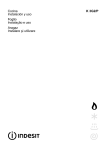
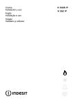
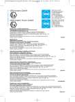
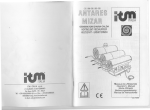
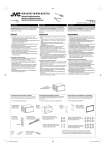
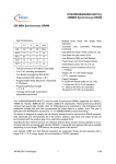
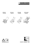
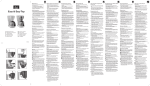
GENERATORI D’ARIA CALDA HEATING UNIT RECHAUFFER GENERATOR DE AER CALD MANUALE PER L’OPERATORE OPERATOR’S MANUAL MODE D’ EMPLOI MANUAL DE UTILIZARE Cod. 2700533 rev.2 del 11-10-2007 TARGHETTA DATI TECNICI – TECHNICAL DATA PLATE – PLAQUE DONNÈES TECHNIQUES – FABRUKSCHILD MIT TECNISCHEN DATEN – PLACA DATOS TECNICOS RIFERIMENTO DI PRODUZIONE PRODUCTION NUMBER NUMÊRO DE PRODUCTION HESTELLUNGSNUMMER NUMERO DE PRODUCCIÒN MODELLO / MODEL MODELE / MODELL MODELO POTENZ.MAX / POWER PUISSANCE HEIZLISTUNG POTENCIA PORTATA D’ARIA SUCCED AIR AIR ASPIRÈ E ANGESAGE LUFT AIRE ASPIRADO CONSUMO GASOLIO DIESEL CONSUMPTION GASOIL CONSOMM. ÖL VERBRAUCH CONSUMICIÓN DIESEL CONOSCENZA DELLA MACCHINA DESCRIPTION OF THE MACHINE CONNAISANCE DE LA MACHINE DESCRIEREA MASINII 1-TELAIO / CHASSIS / SOUBASSEMENT/SASIUL 2-CAMERA DI COMBUSTIONE/ COMBUSTION CHAMBER / CHAMBRE DE COMBUSTION/ CAMERA DE COMBUSTIE 3-SCAMBIATORE DI CALORE / HEAT EXCHANGER / ÉCHANGEUR DE CHALEUR/SCHIMBATORUL DE CALDURA 4-PANNELLO DI MANDATA / DELIVERY PANEL / PANNEAU DE REFOULEMENT/PANOUL IESIRE AER CALD 5-GRUPPO VENTILANTE ELICOIDALE / HELICAL FAN UNIT / GROUPE VENTILATEUR HÉLICOÏDAL/GRUPUL ELICE 6-GRIGLIA ANTINFORTUNISTICA / ACCIDENT-PREVENTION GRILL / GRILLA CONTRE LES ACCIDENTS/ GRILAJ DE PROTECIE 7-GRUPPO VENTILANTE CENTRIFUGO / CENTRIFUGAL FAN UNIT / GROUPE VENTILATEUR CENTRIFUGE/ GRUPUL VENTILATOR CENTRIFUGAL 8-PANNELLO PORTAVENTILATORE /FAN HOLDING PANEL / PANNEAU PORTE VENTILATEUR/PANOUL ELICEI 9-PANNELLO DI ISPEZIONE / INSPECTION PANEL / PANNEAU D’ISPECTION/PANOU PENTRU CONTROL 10-GANCI DI SOSPENSIONE / HANGING HOOKS / CROCHET DE SUSPENSION/SUPORTI PENTRU RIDICAT 11-BITERMOSTATO (FAN LIMIT) / BITHERMOSTAT (FAN LIMIT) / DOUBLE THERMOSTAT (FAN LIMIT)/ TERMOSTAT DUBLU(FAN LIMIT) 12-PANNELLO COMANDI / CONTROL PANEL / PANNEAU DES COMMANDES/PANOU DE COMANDà 13-PIASTRA PORTA BRUCIATORE / BURNER PLATE / PLAQUE PORTE BRÛLEUR/SUPORTUL ARZÃTORULUI 14-GUARNIZIONE / GASKET / JOINT/GARNITURà 15-SPIONCINO / PEEPHOLE / JUDAS/OCHI DE CONTROL 16- RACCORDO CANNA FUMARIA / FLUE FITTING / RACCORD CARNEAU MONTANT/RACORDUL COSULUI 17-PANNELLO SUPERIORE / UPPER PANEL / PANNEAU SUPÉRIEUR/PANOUL SUPERIOR 18-PANNELLO LATO CAMINO / FLUE SIDE PANEL / PANNEAU CÔTÉ CHEMINÉE/PANOUL LATERAL 19-PANN.LATO QUADRO COMANDI / SWITCHBOARD SIDE PANEL / PANNEAU CÔTÉ TABLEAU DE BORD/ PANOUL DE COMANDà 20-PANNELLO LATO BRUCIATORE / BURNER SIDE PANEL / PANNEAU CÔTÉ BRÛLEUR/PANOUL ARZÃTORULUI DIMENSIONI SIRIO CON VENTILATORE ELICOIDALE SIRIO DIMENSIONS WITH HELICAL FAN DIMENSIONS SIRIO AVEC VENTILATEUR HÉLICOïDAL DIMENSIUNI SIRIO CU ELICE ELICOIDALà B Ø2 A Ø1 C D Modello A B C D Ø1 Ø2 SIRIO 50 SIRIO 80 SIRIO 130 SIRIO 160 800 1020 1150 1300 600 650 750 750 800 1020 1100 1250 400 400 400 400 150 150 150 150 400 500 600 700 CARATTERISTICHE TECNICHE SIRIO/SIRIO TECHNICAL DATA/CARACTÉRISTIQUES TECHNIQUES/CARACTERISTICI TECNICE MODELLO/MODEL/MODELE/MODELUL U.M. kW kcal/h BTU/h kW kcal/h BTU/h 50EM 52 45.000 177.429 46,28 39.800 157.939 50CM 52 45.000 177.429 46,28 39.800 157.939 80EM 91 78.000 310.500 82,81 71.216 282.605 80CM 91 78.000 310.500 82,81 71.216 282.605 130EM 115 99.000 392.391 103,5 89.010 353.214 130CM 115 99.000 392.391 103,5 89.010 353.214 160ET 156 134.000 532.287 141,96 122.085 484.466 160CT 156 134.000 532.287 141,96 122.085 484.466 % 90 90 89 89 90 90 89 89 kg/h G.P.H. 4,36 1,00 4,36 1,00 7,64 1,50 7,64 1,50 9,65 2,50 9,65 2,50 13,10 3,50 13,10 3,50 ATM 12 12 12 12 11 11 11 11 PORTATA D'ARIA/AIR FLOW/DÉBIT EN AIR/DEBITUL DE AER m/h 5.000 5.000 8.000 8.000 11.000 11.000 13.000 13.000 PRESSIONE STATICA/STATIC PRESSURE/PRESSION STATIQUE/PRESIUNE STATICA Pa 100 150 150 200 180 230 180 230 POTENZA MOTORE/MOTOR POWER/PUISSANCE MOTEUR/PUTEREA MOTORULUI kW 0,440 0,550 2x0,440 0,736 2x0,440 2x0,736 2x0,550 2x1,100 A 2,3 4,6 2x2,3 5,2 2x2,3 2x5,2 2x1,6 2x4,3 V-Hz 230-50 230-50 230-50 230-50 230-50 230-50 400-50 400-50 Ø mm kg 400 125 400 135 500 200 500 215 600 260 600 280 700 290 700 320 m³ 1 1 1,45 1,45 2,60 2,60 5 5 PORTATA NOMINALE/NOMINAL FLOW/DÉBIT NOMINAL/DEBITUL NOMINAL PORTATA TERMICA/TERMAL POWER/DÉBIT THERMIQUE/ PUTEREA TERMICA RENDIMENTO DI COMBUSTIONE/COMBUSTION EFFICIENCY/RENDEMENT DE COMBUSTION/ RANDAMENTUL BRUCIATORE A GASOLIO/DIESEL BURNER/BRULEUR A GASOIL/ARZATOR PE MOTORINA PORTATA/FLOW/DÉBIT/DEBITUL UGELLO/NOZZLE/GICLEUR/DUZA PRESSIONE POMPA/PUMP PRESSURE/PRESSION DE POMPE/PRESIUNE POMPA VENTILATORE/FAN/VENTILAT/ELICE ASSORBIMENTO MOTORE/MOTOR ELECTRICAL INPUT/ABSORPTION MOTEUR/PUTEREA ABSORBITA ALIMENTAZIONE ELETTRICA/MOTOR ELECTRICALINPUT/ALIMENTATION ÈLECTRIQUE RACCORDO PER GUAINA/JUNCTION OF SPRING COVER /RACCORD POUR GAINÈ/RACORDUL PENTRU GARNITURA PESO/WEIGHT/POIDS/GREUTATE VOLUME GENERATORE/VOLUME/VOLUME GÉNÉRATEUR/VOLUMUL GENERATORULUI Pannello comandi Legenda: 2 1. Pulsante di accensione della macchina 2. Pulsante di funzionamento ventola MANUALE / AUTOMATICO. 3. Pulsante di Reset 1 3 Descrizione La nuova gamma di generatori d'aria calda ITM serie SIRIO, adotta uno scambiatore di calore a grande superficie di scambio termico e una camera di combustione a forma conica, uniformemente raffreddati dall'aria che li attraversa. - Una speciale apparecchiatura elettrica garantisce un funzionamento completamente automatico. - La facilità di installazione e l'elevato standard qualitativo, sono solo alcune delle caratteristiche che li contraddistinguono. - Destinati al riscaldamento di serre e cantieri, devono essere equipaggiati con bruciatori. - Telaio in profilato di alluminio. - Pannellatura esterna completamente in acciaio inossidabile Aisi 430 con contropannellatura interna in lamiera in acciaio zincato. - Camera di combustione e scambiatore di calore in acciaio inox Aisi 430. - Ventilatore elicoidale o centrifugo. - Airstat di sicurezza con comando bitermostatico del ventilatore (FANCONTROL) e del bruciatore (LIMIT CONTROL). - Apparecchiatura elettrica. - Piastra porta bruciatore. INSTALLAZIONE Imballo e trasporto Il generatore d’aria calda viene normalmente spedito in gabbia di legno e protetto da film di polietilene. Il trasporto, lo scarico e la messa in posizione devono essere eseguiti con adeguati mezzi, con la massima cura, evitando i colpi violenti. Ganci di sollevamento Il generatore è dotato di quattro ganci di sollevamento, atti alle operazioni di scarico al ricevimento del materiale. L’utilizzo dei ganci, implica la massima cura, evitando i colpi violenti. Prima di agganciare le corde di sollevamento, accertarsi che i ganci siano bene avvitati, evitando nel modo più assoluto la rotazione del carico sospeso (i ganci potrebbero svitarsi). La sicurezza di tenuta dei ganci è assicurata distribuendo uniformemente il peso sui quattro punti di sollevamento, assicurarsi quindi che le corde di sollevamento siano di adeguato spessore . Ricovero del prodotto Frequentemente il prodotto viene ritirato con notevole anticipo rispetto alla sua installazione. In tal caso si raccomanda di ricoverare il materiale in adeguato locale, ben protetto dalle intemperie e dall'umidità. Raccordo camino Si deve tenere presente che tutti gli apparecchi devono avere un collegamento diretto a canna fumaria di sicura efficienza. Il collegamento, raccordo camino Generatore / Canna Fumaria, deve rispondere ai seguenti requisiti: - Avere per tutta la lunghezza sezione uguale o maggiore di quella dell'attacco del tubo di scarico del Generatore ed essere isolato termicamente. - Essere dotato di sportello antiscoppio. - Avere un andamento ascensionale con pendenza non inferiore al due per cento e lunghezza non superiore ai due metri. - Non avere cambiamenti di direzione con angoli minori di 90°. - Essere a tenuta perfetta. Canna fumaria Particolare importanza riveste la canna fumaria in quanto il rendimento della combustione è direttamente condizionato dal modo in cui vengono scaricati i fumi di combustione. La forza ascensionale dei fumi è proporzionale all'altezza del condotto e alla differenza di temperatura; al di sotto di una certa altezza, lo scarico non è bene assicurato. Si ammette generalmente che un condotto abbia almeno un’altezza di tre o quattro metri. Il percorso verticale della canna fumaria in ogni caso deve essere tale da assicurare in corrispondenza dell'attacco del Generatore una depressione di 0,5 mm. c.a.. La canna fumaria, deve essere predisposta in modo da rendere facile la pulizia, per questo deve avere, sia alla base sia alla sommità, degli sportelli d'ispezione. Importanza particolare assume il comignolo; la forma e l'ubicazione devono consentire di evitare nel modo più assoluto il ritorno dell'aria dall'alto verso il basso. Non sono ammessi per l'esecuzione della canna fumaria tubi di ferro se non adeguatamente rivestiti; nel qual caso il loro peso non deve gravare sul Generatore. Installazione L’installazione dell'apparecchio deve essere effettuata da personale qualificato, nel rispetto delle vigenti disposizioni di legge e delle Norme di Sicurezza per l’esecuzione degli impianti elettrici. La posizione di installazione dovrà essere scelta tenendo conto che per motivi di manutenzione attorno al generatore dovranno essere lasciati i seguenti spazi liberi: -Anteriormente cm. 1.00. -Posteriormente cm. 60. -Lateralmente (almeno un lato) cm. 60. Collegamenti elettrici I collegamenti elettrici, vanno eseguiti attenendosi allo schema elettrico. Eventuali schemi elettrici forniti a parte avranno valore preminente, rispetto a quelli riportati nel presente libretto istruzioni di montaggio e dovranno quindi essere utilizzati per la realizzazione dei collegamenti elettrici. Il bruciatore dovrà essere collegato elettricamente in base al proprio schema elettrico. Se non diversamente previsto nell’ordine, i generatori monofase sono predisposti per alimentazione elettrica di V. 230/1/50 Hz. e quelli trifase V. 400/3/50 Hz. Il collegamento e la messa a terra dell'impianto elettrico e della macchina sono indispensabili, oltre che obbligatori a Norma di legge. L’interruttore generale magnetotermico, non è previsto nella nostra fornitura, se ne raccomanda vivamente la sua installazione, ciò anche per rendere l'impianto conforme alle Norme. Collegamenti elettrici motori trifase TERMOSTATO AMBIENTE Non previsto tra gli accessori di nostra fornitura, dovrà essere fornito dall'installatore; se ne raccomanda l'installazione ad una altezza di circa metri 1,7 da terra ed in una posizione non esposta alle correnti d'aria. BRUCIATORE I generatori d'aria calda sono previsti per funzionare con bruciatori di gasolio. L’installazione del bruciatore va eseguita attenendosi alle istruzioni di montaggio del bruciatore stesso; la portata del combustibile va tarata esclusivamente in base ai valori della potenza termica dei generatore indicata sulla Tabella dati tecnici. BI-TERMOSTATO (FAN-LIMIT) E’ fornito già collegato elettricamente e tarato e, non deve essere manomesso; E' opinione diffusa presso gli utilizzatori, che intervenendo sul FAN-LIMIT si ottengano maggiore o minore temperatura in ambiente. Si tratta di una opinione errata, in quanto il bi-termostato ha lo scopo di assicurare un funzionamento automatico del generatore e di arrestare il bruciatore nei casi di surriscaldamento dello scambiatore di calore. La sua taratura è fissa. Bitermostato HONEYWELL Il bitermostato FAN-LIMIT ha l’elemento sensibile posizionato alla bocca di mandata dell’aria calda ed ha la funzione di comandare sia l’avvio che l’arresto del gruppo ventilante (funzione FAN), sia l’arresto in sicurezza del bruciatore dovuto ad eventuale sovratemperatura (funzione LIMIT). FUNZIONE FAN Quando la temperatura dell’aria in prossimità dell’elementosensibile raggiunge il valore impostato sul quadrante graduato del bitermostato (10°C e dopo circa un minuto dall’accensione del bruciatore), il contatto elettrico del termostato si chiude e avviene la partenza del gruppo ventilante. Quando la temperatura dell’aria in prossimità dell’elemento sensibile si abbassa oltre il valore impostato sul quadrante graduato del bitermostato (25°C e dopo circa 2/3 minuti dallo spegnimento del bruciatore), il contatto elettrico del termostato si apre ed avviene l’arresto del gruppo ventilante. FUNZIONE LIMIT Quando a causa di una qualsiasi anomalia di funzionamento l’aria in prossimità dell’elemento si surriscalda e la temperatura raggiunge il valore impostato sul quadrante graduato del bitermostato (80°/100°C), il contatto elettrico del termostato si apre provocando l’arresto del solo bruciatore. 1. Quadrante graduato 2. Fori di fissaggio 3. Indice di intervento sicurezza LIMIT 4. Indice temperatura avvio ventilatore 5. Indice temperatura arresto ventilatore 6. Ponte metallico (deve essere tolto) 7. Collegamenti funzione limit 8. Pulsante rosso sblocco intervento LIMIT 9. Collegamenti funzione FAN 10.Pulsante bianco ventilazione AUTOMATICA/MANUALE ACCENSIONE GENERATORE Provvedere al controllo ed alla verifica della giusta corrispondenza della tensione di rete. Controllare immediatamente l'assorbimento del motore elettrico, operazione quest'ultima che si esegue con apposita pinza amperometrica, accertandosi che lo stesso non sia superiore a quello indicato sulla targa del motore e che indichiamo anche nella Tabella dati tecnici; nel caso si sostituirà il gruppo motore - ventola secondo i modelli. Eseguiti tali controlli, regolare il termostato ambiente sul valore della temperatura desiderata (contatti chiusi). Il bruciatore partirà automaticamente, provvedendo al riscaldamento della camera di combustione: dopo qualche minuto sempre automaticamente entrerà in funzione anche il ventilatore. SPEGNIMENTO DEL GENERATORE Per spegnere il generatore eseguire le seguenti operazioni: A. Posizionare il termostato ambiente al valore minimo (contatti aperti) ed attendere che il ventilatore si sia fermato. B. Disinserire l'interruttore dell'alimentazione elettrica posto sul generatore. C. Disinserire l'interruttore generale magnetotermico dell'alimentazione elettrica. MANUTENZIONE Per un buon funzionamento è indispensabile eseguire periodicamente dei controlli, regolazioni e manutenzioni generali. Ogni operazione va eseguita togliendo preventivamente la tensione elettrica di rete, intervenendo sull'interruttore generale. Controllare l'efficienza del Fan-Limit. Controllare che viti e bulloni in generale non si siano allentati. La pulizia dello scambiatore di calore va eseguita a fine stagione invernale: si effettua togliendo il bruciatore, la piastra porta bruciatore, il pannello esterno ed il coperchio d'ispezione della camera di combustione. Far scorrere l’apposito scovolo nei tubi di passaggio dei fumi, avendo cura di raschiarne accuratamente le pareti facendo cadere i residui della combustione (fuliggine), in camera di combustione. La stessa operazione va eseguita poi per la camera di combustione e per la cassa fumi posteriore, per poi rimontare il tutto, sostituendo ove necessario le guarnizioni isolanti di tenuta in fibra di vetro. Se la camera di combustione dovesse risultare particolarmente sporca significa che il bruciatore non funziona bene e necessita di controllo e regolazione. La pulizia ed il controllo del bruciatore sono importanti per il buon funzionamento e l'efficienza dell'impianto; per le relative operazioni di manutenzione, Vi rimandiamo alle istruzioni del bruciatore stesso. Il raccordo della canna fumaria si pulisce con un aspiratore. Controllare l'efficienza del camino e la portata del combustibile. Controllare il Fan-Limit. Controllare motore e condensatore. RICERCA GUASTI SBALZI DI TENSIONE Possono provocare la bruciatura del motore ventilatore. E' opportuno accertarsi che la tensione di alimentazione non vari più dei 5 - 10%, rispetto a quella prevista per l'alimentazione. BRUCIATORE NON FUNZIONA Controllare che i collegamenti elettrici siano stati eseguiti correttamente e che arrivi tensione. In assenza di termostato ambiente è necessario eseguire il collegamento elettrico (ponte) tra i corrispondenti morsetti in apparecchiatura elettrica. BRUCIATORE NON SI ACCENDE Accertarsi che il termostato ambiente sia inserito e che il Limit non sia intervenuto; che le protezioni bruciatore non siano intervenute, controllare e ripristinare. GENERATORE FUNZIONA IN CONTINUAZIONE Verificare che la potenza termica del Generatore sia adeguata all'ambiente da riscaldare; controllare che la portata del combustibile non sia inferiore a quella indicata sulla apposita targhetta caratteristiche; che il generatore sia ben pulito. FIAMMA MOLTO LUMINOSA Controllare che il Generatore non sia sporco; che l'aerazione del locale sia sufficiente per una buona combustione; controllare che la portata termica del bruciatore sia corrispondente a quella di targa del generatore. Controllare e regolare la serranda di regolazione dell'aria al bruciatore. ODORE DI GAS INCOMBUSTI Controllare internamente che lo scambiatore di calore sia ben pulito; controllare l'efficienza del tiraggio camino ed il regolare funzionamento del bruciatore. VENTILATORE NON PARTE Controllare e regolare o sostituire il FAN-LIMIT. Controllare motore e condensatore se bruciati, riparare o sostituire e ricercare le cause. INTERVENTO DEL LIMIT Verificare l'apertura di serrande poste sui condotti dell'aria. Rimuovere eventuali ostruzioni sui condotti. Eccessiva portata di combustibile. Cattivo funzionamento dei bruciatore. Insufficiente tiraggio del camino. Controllare e regolare o sostituire il FAN – LIMIT DICHIARAZIONE DEL FABBRICANTE La macchina, oggetto di questa dichiarazione è destinata a funzionare in accoppiamento con bruciatori di gasolio; destinata al riscaldamento di locali esenti da polveri, granuli, trucioli, grassi ecc., nel seguente campo di temperature -20 +40 °C.; alle condizioni indicate sulla targa “Caratteristiche Tecniche” applicata sul prodotto. E' fatto divieto di mettere in servizio la macchina, oggetto di questa dichiarazione, con bruciatori di gas ad aria soffiata che non siano stati preventivamente certificati, presso laboratori accreditati in base alla Direttiva Gas 90/396/CEE. ISTRUZIONI/INSTRUCTIONS/INTRODUCTION/INSTRUCTIUNI: 1. Interruttore generale con fusibili da installarsi a cura del cliente. Main switch with fuses to be installed by the customer. Interrupteur général avec fusibles à installer par le client. Întreupãtor general cu siguranze ce se vor instala de cãtre client 2. È obbligatorio collegare la macchina a terra. It is compulsory to ground the machine. Il est obligatoire relier la machine à la terre. Este obligatoriu înpãmîntarea masinii. 3. Per il funzionamento a sola ventilazione intervenire sul FAN-LIMIT. For working only in fan-mode, oprate on FAN-LIMIT device. Pour le fonctionnement de seule ventilation, intervenir sur le FAN-LIMIT. Pentru functionarea doar a ventilatiei interveniti pe FAN-LIMIT. 4. In assenza di termostato ambiente, eseguire ponte tra i morsetti 12-13 della morsettiera. In absence of the room thermostat, make a bridge between clamp 12-13 of the terminal block. En absence du thermostat ambiance, faire pont entre les borne 12-13 et la plaque à bornes. În absenta termostatului, executati o punte între contactele 12-13. 5. In assenza della linea termostatica sul bruciatore, eseguire ponte tra i morsetti 6-12 e collegare il bruciatore ai morsetti 7-11. In absence of the room thermostat line on the burner, make a bridge between clamps 6-12 and connect the burner to clamp 7-11. En absence de la ligne thermostatique sur le brûleur, effectuer pont entre les borns 6-12 et relier aux bornse 7-11. În absenta liniei termostatice pe arzãtor,executati o punte între contactele 6-12 si conectati arzãtorul la contactele 7-11. 6. I collegamenti elettrici da eseguire sono indicati a tratteggio. The electrical connection to execute are show by sketching. Les liaisons électriques à effectuer sont indiquées par une ligne à traits interrompus. Conexiunile electrice ce se vor executa sunt indicate cu linii întrerupte. 7. Ove non previsto sul bruciatore, proteggere la linea del termostato ambiente con adeguato fusibile. In case it is not provided on the burner, protect the room thermostat line by an adequate fuse. Là ou ce n’est pas prévu sur le brûleur, protéger la ligne du thermostat ambiance Control panel Key: 1. Ignition button 2 2. MANUAL/AUTOMATIC fan switch 3. RESET button 1 3 Description The new range of hot air generators ITM series SIRIO is equipped with a wide surface heat exchanger and a cilindric combustion chamber, uniformelly cooled by the air passing through. - A special electrical equipment allows a fully automatic working. - The easy installation and the high-quality standard are only some of the distinguishing features of these machines. -They are suitable for greenhouses and building sites heating and must be equipped with burners. - Aluminium structural frame - External body made of AISI 430 stainless steel with internal thermal insulation paneling made of zinc plated steel. - AISI 430 stainless steel combustion chamber and heat exchanger. - Helical or centrifugal fan. - Safety airstat with bithermostatic fan (FAN-CONTROL) and burner (LIMIT CONTROL) control. - Electrical equipment. - Burner plate. INSTALLATION Packing and transport The hot air generator is normally forwarded with a wood cage and a polyethylene protection sheet. Transport, unloading and positioning have to be carried out with appropriate means and the maximum care, avoiding violent shocks. Lifting hooks The generator is equipped with four lifting hooks for unloading operations on receipt of the machine. The use of the hooks implies the utmost care, avoiding violent shocks. Before fastening the lifting cables, make sure that the hooks are properly screwed down, absolutely avoiding the whirling round of the suspended machine (the hooks could unscrew). In order to ensure the maximum resistance of the hooks, the weight of the machine has to be evenly distributed among the four lifting points; also make sure that the lifting cables are of an adequate section. Product storage The machine is often delivered much earlier than the moment of its installation. In this case it is recommended to store the machine in a suitable room, protected from the inclemency of the weather and from moisture. Chimney connection All the machines must have an efficient direct connection with a flue. The connection between the connector of the heater and the flue has to fulfil the following requirements: - To have a section equal or larger than the fumes discharge connection of the generator and to be thermally insulated. - To be equipped with a blast prevention door - To have an ascending development, with a gradient not less than 2% and a length not more than 2 metres. - Not to have direction changes with gradient lower than 90°. - To have a perfect seal. Flue The flue is particularly important, as the combustion efficiency is directly conditioned by the way the combustion fumes are exhausted. The ascending strength of the fumes is proportional to the height of the duct and the difference of temperature; below a certain height, the fumes exhaust is not adequate. Normally the duct has to be at least 3-4 metres high. In any case, the vertical course of the flue must guarantee a suction pressure of 0,5 mm. c.a., measured at the point of connection with the generator. The flue has to be provided for an easy cleaning; therefore there must be some inspection doors both at the base and at the top of the flue. The chimneystack is also very important; its shape and location have to avoid the air backflow downwards. Iron pipes cannot be used as a flue if they are not properly covered; in this case they must not weigh on the generator. Installation The installation of the machine must be carried out by qualified personnel, respecting the laws and the safety norms in force for the execution of the electrical installations. For maintenance reasons, the place of installation shall consider the following empty spaces around the heater: - At the front: cm. 100. - At the back: cm. 60. - From the side (at least one): cm. 60. Electrical connections The electrical connections must be done following the wiring scheme. Any wiring scheme supplied separately from this manual shall be considered as replacing the ones of the manual and shall be used for the electrical connections. The burner shall be connected following its own wiring scheme. If not otherwise stated in the order, the single phase hot air generators are preset for 230V/50Hz and the three phase ones are preset for 400V/50Hz power supply. The connection and the grounding of the electrical installation and the machine are indispensable and compulsory according to law. The main magnetothermal switch is not supplied with the machine; therefore its installation is warmly recommended, in order to make the plant according to law. Three phase motor electrical connection ROOM THERMOSTAT It is not supplied with the machine, therefore it has to be supplied by the installer; the recommended installation height of the thermostat is at about 1,7 mt. from the ground and not exposed to air draught. BURNER The hot air generators are designed to work with air blown, not pressurized, diesel burners. The installation of the burner must be effected following the assembling instructions of the burner; the fuel delivery has to be adjusted exclusively on the basis of the thermal power values of the generator, which are shown on the technical data table. BITHERMOSTAT (FAN-LIMIT) This is supplied electrical connected and set and must not be tampered with. Many users think that you get higher or lower ambient temperature by adjusting the FAN-LIMIT. This is wrong, as the bi-thermostat ensures that the heating unit operates automatically and stops the burner if the heat exchanger is overheating. Its setting is permanent. FAN MODE When the air temperature around the sensitive element reaches the reading preselected on the graduated dial of the bi-thermostat (10°C after about one minute from the burner ignition), the electric contact of the thermostat makes the fan group start. When the air temperature around the sensitive element drops beyond the value preselected on the graduated dial of the bi-thermostat (25°C after about 2-3 minutes from the burner stopping), the electric contact opens making the fan group stop. LIMIT MODE In case, due to any working anomaly, the air around the sensitive element overheats and the temperature reaches the reading preselected on the graduated dial of the bithermostat (80°/100°C), the electric contact of the thermostat opens making only the burner stop. 1. Graduated dial 2. Fixing holes 3. LIMIT safety intervention indicator 4. Fan start temperature indicator 5. Fan stop temperature indicator 6. Metallic bridge (to be removed) 7. LIMIT mode connections 8. LIMIT intervention reset red button 9. FAN mode connections 10. Ventilation white button IGNITION Check the correct power supply; then verify immediately the power absorption of the electrical motor by an amperometric pliers and make sure it does not exceed the value shown on the motor rating plate, which is also shown on the technical data table; should this be the case, the motor-fan unit shall be replaced according to the different models. As soon as this controls are carried out, adjust the room thermostat to the desired temperature (closed contacts). The burner shall automatically start and heat the combustion chamber; some minutes later, also the fan shall automatically go into operation. SWITCHING OFF THE GENERATOR To switch-off the generator, execute the following operations: - Set the room thermostat to the lower position (open contacts) and wait for the fan to stop. - Switch off the power switch on the generator. - Switch off the main thermal-magnetic switch (which shall be duly installed by the user). MAINTENANCE For the good working of the machine it is indispensable to carry out some periodic inspections, adjustments and general maintenance. Each operation must be executed after cutting off the power supply, switching off the main switch. Check the Fan-Limit efficiency. Make sure that screws and bolts haven’t loosened. The heat exchanger cleaning must be carried out at the end of winter season: it can be done by removing the burner, the burner plate, the external panel and the combustion chamber inspection cover. Run the apposite tube-brush across the fumes passage tubes, scraping off thoroughly the residual combustion products (soot) and making them fall into the combustion chamber. The same operation has to be done for the combustion chamber and for the back fumes box. Reassemble all the parts after replacing, when necessary, the fiber glass sealing gaskets. Should the combustion chamber be particularly dirty, it means that the burner does not work properly and must be inspected and adjusted. Cleaning and control of the burner are fundamental for the good working and the efficiency of the system. For the burner maintenance operations, read the operator’s manual of the burner. The flue connection has to be cleaned by the means of a vacuum cleaner. Check the efficiency of the chimney and the fuel delivery. Check, adjust or replace the Fan-Limit. Check the motor and the condenser. Should they be burnt out, repair or replace them and try to find out the causes of the trouble. TROUBLESHOOTING SUDDEN VOLTAGE CHANGE It may cause the fan motor burnout. Make sure that the mains voltage does not exceed the voltage provided for the power supply by more than 5 – 10%. THE BURNER DOES NOT WORK Make sure that the electrical connections are properly executed and that the net tension is correct. In the absence of the room thermostat it is necessary to make a direct connection (bridge) between the appropriate clamps of the electrical device. THE GENERATOR WORKS CONTINUOUSLY Check that the thermal power of the generator is adequate to the room to warm; check that the fuel delivery isn’t lower than the value shown on the apposite technical data plate; make sure that the generator is clean. THE FLAME IS VERY BRIGHT Check that the generator isn’t dirty; make sure that the room ventilation is sufficient for a good combustion; check that the thermal power of the burner corresponds to the one shown on the generator data plate. Check and adjust the air regulation shutters of the burner. SMELL OF UNBURNT GAS Check that the heat exchanger is well clean inside; check the efficiency of the chimney draught and adjust the burner working. THE FAN DOES NOT START Check and adjust or replace the FAN-LIMIT. Check the motor and the condenser; should they be burnt out, repair or replace them and try to find out the causes of the trouble. COMING UP OF THE LIMIT Check the opening of the shutters on the air ducts. Remove any possible obstruction of the ducts. Excessive fuel delivery. Bad working of the burner. Inadequate draught of the chimney. Check, adjust or replace the FAN - LIMIT DECLARATION OF THE MANUFACTURER The machine, object of this declaration, is provided for working in combination with diesel gas burners and is provided for heating rooms clear from dust, granules, shavings, grease, etc, within the temperature range from -20 to +40 °C.; at the conditions shown on the “Technical data” plate sticked on the machine. It is forbidden to operate with the machine, object of this declaration, with air blown gas burners not beforehand certified by accredited laboratories, on the basis of the Gas Directive 90/396/CEE. Panneau des commandes Légende: 1. Bouton-poussoir de mise en marche de la machine. 2 2. Bouton-poussoir de fonctionnement ventilateur MANUEL/AUTOMATIQUE. 3. Bouton-poussoir de RESET. 1 3 Description Les générateurs d'air chaud de la nouvelle gamme ITM série SIRIO, sont équipés d'un échangeur de chaleur à grande surface d'échange thermique et d'une chambre de combustion conique, refroidis de façon uniforme par l'air qui les traverse. - Grâce à un appareil électrique spécial le fonctionnement est complètement automatique. - Parmi leurs nombreuses caractéristiques signalons leur facilité d'installation et leur standard élevé de qualité. - Pour le chauffage des serres et des chantiers ils doivent être équipés de brûleurs. - Châssis en profilé d'aluminium. - Panneaux externes entièrement en acier inoxydable Aisi 430 avec panneaux internes en tôle d'acier galvanisé. - Chambre de combustion et échangeur de chaleur en acier inoxydable Aisi 430. - Ventilateur hélicoïdal ou centrifuge. - Airstat de sécurité avec commande du ventilateur (FAN-CONTROL) et du brûleur (LIMIT CONTROL) par double thermostat. - Appareillage électrique. - Plaque de support du brûleur. INSTALLATION Emballage et transport L'expédition du générateur d'air chaud, enveloppé dans une pellicule protectrice de polyéthylène, se fait en général en caisse en bois. Le transport, le déchargement et la mise en place doivent être effectués, avec beaucoup de soins, à l'aide des moyens de soulèvement et de transport adéquats, en évitant les chocs violents. Crochets de soulèvement Le générateur est fourni de quatre crochets de soulèvement pour les opérations de déchargement à la réception du matériel. Il faut utiliser les crochets avec un maximum de soin, en évitant les coups violents. Avant d'accrocher les cordes de soulèvement, s'assurer que les crochets soient vissés correctement. Eviter à tout prix la rotation du chargement suspendu (les crochets pourraient se dévisser). La sécurité de tenue des crochets est assurée si le poids est distribué uniformément sur les quatre points de soulèvement. S'assurer encore que les cordes de soulèvement aient une épaisseur adéquate . Rangement du produit Souvent le produit est livré bien avant la date de son installation. Dans ce cas on recommande de ranger l'appareil dans un local adéquat, bien protégé contre les intempéries et l'humidité. Raccord cheminée Tous les appareils doivent avoir un raccordement direct, sûr et efficace avec le carneau. Le raccordement Raccord cheminée-Générateur-Carneau doit répondre aux conditions requises suivantes : - Avoir dans toute sa longueur une section égale ou supérieure à celle de l'attache du tuyau d'évacuation du Générateur et être isolé thermiquement. - Etre fourni de porte anti-explosion. - Etre ascensionnel avec une inclinaison non inférieure à deux pour-cent et une longueur non supérieure à deux mètres. - Ne pas avoir de changement de direction avec des angles inférieurs à 90°. - Avoir une parfaite étancheité. Carneau Une grande importance est à attribuer au carneau puisque le rendement de la combustion est directement conditionné par la façon dont sont évacués les fumées de combustion. La force ascensionnelle des fumées est proportionnelle à la hauteur du carneau de fumée et à la différence de température ; en dessous d'une certaine hauteur, la correcte évacuation des fumées n'est pas assurée. Généralement, un carneau doit avoir au moins une hauteur de trois ou quatre mètres. Le parcours vertical du carneau doit toujours pouvoir assurer une dépression d'environ 0,5 mm. en correspondance de l'attache du Générateur. Le carneau doit être placé de façon à en faciliter le nettoyage ; pour cette raison, il doit y avoir des portes d'inspection à sa base ainsi qu'à son sommet. La cheminée est très importante ; sa forme et son emplacement doivent absolument pouvoir éviter le retour de l'air du haut vers le bas. Le carneau ne doit pas avoir de tuyaux en fer, à moins qu'ils ne soient revêtus de façon adéquate et, dans ce cas, leur poids ne doit pas être supporté par le Générateur. Installation L'installation de l'appareil doit être effectuée par du personnel qualifié, aux termes de la loi en vigueur et des Normes de Sécurité pour les installations électriques. La position d'installation devra être choisie en tenant compte que pour des raisons d'entretien, autour du générateur il devra y avoir les espaces libres suivants : - Antérieurement cm. 100. - Postérieurement cm. 60. - Latéralement (au moins d'un côté) cm. 60. Branchements électriques Les branchements électriques doivent être effectués en se référant au schéma électrique. Les éventuels schémas électriques fournis à part auront la priorité par rapport à ceux que vous trouverez dans ce manuel d'instructions de montage. Ce sont donc ces schémas fournis à part que vous devrez utiliser pour les branchements électriques. Le brûleur devra être branché électriquement sur la base de son propre schéma électrique. Au cas où la commande ne prévoirait d'autres indications, les générateurs monophasés sont prévus pour une alimentation électrique de V. 230/1/50 Hz., tandis que les générateurs triphasés sont prévus pour une alimentation électrique de V. 400/3/50 Hz. Le branchement et la mise à la terre de l'installation électrique et de la machine sont indispensables et obligatoires aux termes de la loi. L'interrupteur général magnétothermique n'est pas prévu dans notre fourniture, néanmoins on recommande vivement son installation pour que l'installation électrique soit conforme aux Normes. Branchements électriques moteurs triphase THERMOSTAT D'AMBIANCE Le thermostat d'ambiance n'est pas prévu dans notre fourniture. Il devra être fourni par l'installateur. On recommande son installation à une hauteur d'environ 1,7 mètres du sol et dans une position non exposée aux courants d'air. BRULEUR Les générateurs d'air chaud sont prévus pour fonctionner avec des brûleurs à gasoil. L'installation du brûleur doit être effectuée en suivant les instructions de montage du brûleur même ; la portée du combustible doit être tarée exclusivement sur la base des valeurs de la puissance thermique du générateur, indiquée sur le Tableau données techniques. DOUBLE THERMOSTAT (fan-limit) L'appareil est fourni étalonné, avec son branchement électrique et ne doit pas être altéré ; les utilisateurs pensent souvent qu'en intervenant sur le FAN LIMIT ils peuvent augmenter ou diminuer la température ambiante. Cette idée est fausse car le double thermostat sert uniquement à garantir le fonctionnement automatique du générateur et à arrêter le brûleur en cas de surchauffe de l'échangeur de chaleur. Sa température est fixe. Double thermostat HONEYWELL Le double thermostat FAN-LIMIT a son élément sensible placé à l'embouchure du refoulement de l'air chaud et sert à commander le démarrage et l'arrêt du groupe de ventilation (fonction FAN), ainsi que l'arrêt de sécurité du brûleur en cas de surchauffe (fonction LIMIT). FONCTION FAN Lorsque la température de l'air à proximité de l'élément sensible atteint la valeur introduite sur le cadran gradué du double thermostat (10°C et une minute environ après l'allumage du brûleur), le contact électrique du thermostat se ferme et le groupe de ventilation démarre. Lorsque la température de l'air à proximité de l'élément sensible descend au-dessous de la valeur introduite sur le cadran gradué du double thermostat (25°C et 2 à 3 minutes environ après l'extinction du brûleur), le contact électrique du thermostat s'ouvre et le groupe de ventilation s'arrête. 1. Cadran gradué 2. Trous de fixage 3. Index d’intervention sûreté LIMIT 4. Index température départ ventilateur 5. Index température arrêt ventilateur 6. Pont métallique (doit être enlevé) 7. Liaisons fonction LIMIT 8. Bouton rouge pour déblocage intervention LIMIT 9. Liaisons fonction FAN 10. Bouton blanc ventilation AUTOMATIQUE/MANUELLE ALLUMAGE GENERATEUR Contrôler et vérifier que le voltage du réseau corresponde à celui du générateur. Contrôler immédiatement l'absorption du moteur électrique (opération à effectuer à l'aide de la pince ampèremétrique spécifique) et s'assurer qu'elle ne soit pas supérieure à celle qui est indiquée sur la plaque du moteur et sur le Tableau données techniques ; au cas contraire on devra remplacer le groupe moteur-ventilateur selon les modèles. Après avoir effectué ces contrôles, régler le thermostat d'ambiance sur la valeur de la température désirée (contacts fermés). Le brûleur démarrera automatiquement et réchauffera la chambre de combustion ; après quelques minutes, le ventilateur entrera automatiquement en fonction. ARRET DU GENERATEUR Pour éteindre le générateur, effectuer les opérations suivantes : A. Positionner le thermostat d'ambiance sur la valeur minimum(contacts ouverts) et attendre que le ventilateur s'arrête. B. Débrancher l'interrupteur de l'alimentation électrique placé sur le générateur. C. Débrancher l'interrupteur général magnétothermique de l'alimentation électrique (dont l'installation est à vos soins). ENTRETIEN Pour un bon fonctionnement, il est indispensable d'effectuer périodiquement des contrôles, des réglages et un entretien général. Avant toute opération, il faut toujours couper le courant en agissant sur l'interrupteur général. Contrôler l'efficacité du FanLimit. Contrôler que les vis et les écrous, en général, ne sont pas desserrés. Le nettoyage de l'échangeur de chaleur doit être effectué à la fin de l'hiver : il faut enlever le brûleur, la plaque porte brûleur, le panneau extérieur et le couvercle d'inspection de la chambre de combustion. Faire glisser le spécial écouvillon dans les tuyaux de passage des fumées, en prenant soin de bien racler les parois et de faire tomber les résidus de la combustion (suie) dans la chambre de combustion. Il faut ensuite effectuer la même opération pour la chambre de combustion et pour le caisson fumées postérieur. Remonter enfin le tout en remplaçant, si nécessaire, les joints isolants d'étancheité en fibre de verre. Si la chambre de combustion est particulièrement sale, cela signifie que le brûleur ne fonctionne pas correctement et qu'il nécessite d'un contrôle et réglage. Le nettoyage et le contrôle du brûleur sont importants pour le bon fonctionnement et l'efficacité de l'installation ; pour ce qui concerne les opérations d'entretien du brûleur, voir les instructions du brûleur même. Le raccord du carneau doit être nettoyé à l'aide d'un aspirateur. Contrôler l'efficacité de la cheminée et la portée du combustible. Contrôler, régler ou remplacer le Fan-Limit. Contrôler le moteur et le condensateur. S'ils RECHERCHE PANNES SAUTS DE TENSION Les sauts de tension peuvent griller le moteur ventilateur. Il faut contrôler que la tension d' alimentation ne varie jamais de plus de 5-10 % par rapport à celle qui a été prévue pour l'alimentation. LE BRULEUR NE FONCTIONNE PAS Contrôler que les branchements électriques ont été effectués correctement et que la tension arrive. En l'absence du thermostat d'ambiance, il est nécessaire d'effectuer la connection électrique (pont) entre les bornes correspondantes dans l'appareillage électrique. LE BRULEUR NE S'ALLUME PAS S'assurer que le thermostat d'ambiance est inséré et que le Limit n'est pas intervenu ; s'assurer que les protections du brûleur ne sont pas intervenues, contrôler et remettre à l'état initial. LE GENERATEUR FONCTIONNE SANS ARRET Vérifier que la puissance thermique du Générateur est proportionnée à l'endroit à réchauffer ; contrôler que la portée du combustible n'est pas inférieure à celle qui est indiquée sur la plaquette des caractéristiques ; contrôler que le générateur est propre. FLAMME TRES LUMINEUSE Contrôler que le Générateur n'est pas sale et que l'aération de la pièce est suffisante pour une correcte combustion ; contrôler que la portée thermique du brûleur est correspondante à celle de la plaque du générateur. Contrôler et régler le rideau de réglage de l'air au brûleur. ODEUR DE GAZ NON BRULES Contrôler que l'échangeur de chaleur est bien propre à l'intérieur; contrôler l'efficacité du tirage de la cheminée et le fonctionnement correct du brûleur. LE VENTILATEUR NE DEMARRE PAS Contrôler et régler, ou remplacer le FAN-LIMIT. Contrôler le moteur et le condensateur s'ils sont grillés; les réparer ou les remplacer et en rechercher les causes. INTERVENTION DU LIMIT Vérifier l'ouverture des rideaux placés sur les conduits d'air. Enlever les éventuelles obstructions sur les conduits. Portée excessive de combustible. Mauvais fonctionnement du brûleur. Tirage insuffisant de la cheminée. Contrôler et régler ou remplacer le FAN-LIMIT. DECLARATION DU FABRICANT La machine qui fait l'objet de cette déclaration est destinée à fonctionner avec des brûleurs de gasoil; elle est destinée au chauffage de lieux sans poussières, granules, copeaux, graisses etc. et dans un champ de températures de -20° à +40° C.; aux conditions indiquées sur la plaque "Caractéristiques Techniques" appliquée sur le produit. Il est interdit de mettre en service la machine qui fait l'objet de cette déclaration, avec des brûleurs de gaz à air soufflé qui n'ont pas été préalablement certifiés, auprès de laboratoires attitrés sur la base de la Directive Gaz 90/396/CEE. Z.I. Albarè di Costermano Via Tasso, 35/39 VR, Italy ZEUS - PEGASUS SIRIO - HERCULES IT DICHIARAZIONE DI CONFORMITÀ CE Dichiariamo con la presente, che la macchina qui di seguito indicata,in base alla sua concezione e al tipo di costruzione, e nella versione da noi introdotta sul mercato, è conforme ai relativi requisiti fondamentali di sicurezza e di sanità delle direttive della CE .In caso di modifiche apportate alla macchina senza il nostro accordo, questa dichiarazione perdela sua validità. Prodotto: ZEUS - PEGASUS - SIRIO - HERCULES Numero di serie:(Vedi targhetta d’identificazione della macchina) Direttive CE pertinenti : 98/37/CEE; 2006/95/CE; 89/336/CEE Mediante accorgimenti interni, è stato assicurato che gli apparecchi di serie siano sempre conformi ai requisiti delle attuali direttive CE. UK EU DECLARATION OF CONFORMITY We hereby declare that the equipment described below conforms to the relevant fundamental safety and health requirements of the appropiate EU Directives, both in its basic design and construction as well as in the version marketed by us. This declaration will cease to be valid ifany modifications are made to the machine without our express aproval. Product: ZEUS - PEGASUS - SIRIO - HERCULES Serial number :(see rating plate) Relevant EU Directives : 98/37/CEE; 2006/95/CE; 89/336/CEE Appropiate internal measures have been taken to ensure that series-production units conform at all times to the requirements of current EU Directives. FR DÉCLARATION DE CONFORMITÉ EUROPÉENNE Par la présente, nous déclarons que la machine ci-après répond, de par sa conception et sa construction ainsi que de par le modèle que nous avons mis sur le marché, aux exigences de sécurité et d’hygiène en vigueur de la directive européenne. Produit: ZEUS - PEGASUS - SIRIO - HERCULES Numéro de série (voir plaque signalétique de l’appareil) Directive européenne en vigueur: 98/37/CEE; 2006/95/CE; 89/336/CEE La conformité permanente des appareils de série avec les exigences consignées dans les directives actuelles de la CE est garantie par des mesures internes. PT DE EG-KONFORMITÄTSERKLÄRUNG Hiermit erklären wir, daß die nachfolgend bezeichnete Maschine aufgrund ihrer Konzipierung und Bauart sowie in der von uns in Verkehr gebrachten Ausführung den unten aufgeführten EG-Richtlinien entspricht. Bei einer nicht mit uns abgestimmten Änderung der Maschine verliert diese Erklärung ihre Gültigkeit. Produkt: ZEUS - PEGASUS - SIRIO - HERCULES Seriennummer: (siehe Geräteschild) Einschlägige EG-Richtlinien : 98/37/CEE; 2006/95/CE; 89/336/CEE Es ist durch interne Maßnahmen sichergestellt, daß die Seriengeräte immer den Anforderungen der aktuellen EG-Richtlinien. ES DECLARACIÓN DE CONFORMIDAD DE LA UNIÓN EUROPEA Por la presente declaramos los abajo firmantes que la máquina designada a continuación cumple, tanto por su conceptión y clase de construcción como por la ejecución que hemos puesto en circulación, las normas fundamentales de seguridad y protección de la salud formuladas en las directivas comunitarias correspondientes. La presente declaración pierde su validez en caso de alteraciones en la máquina efectuadas sin nuestro consentimiento explicito. Producto: ZEUS - PEGASUS - SIRIO - HERCULES Número di serie:(véase la placa de caracteristicas del aparato) Directivas comunitariasaplicables: 98/37/CEE; 2006/95/CE; 89/336/CEE Mediante una serie de medidas internas, queda asegurado que los aparatos de serie cumplan siempre las exigencias formuladas en las directivas comunitarias actuales. NL CE - DECLARAÇÃO DE CONFORMIDADE Nós declaramos pelo presente instrumento que a máquina abaixo indicada corresponde, na sua concepção bem como no tipo por nós comercializado, às exigências básicas de segurança e de saúde da directiva da CE. Se houver uma modifição na máquina sem o nosso consentimento prévi, a presente declaração perderá a sua validade. EU-CONFORMITEITSVERKLARING Hiermee verklaren wij dat de hierna vermelde machine op grond van haar concipiëring en constructie en in de door ons in omloop gebrachte uitvoering beantwoordt aan de desbetreffende veiligheids-en gezondheidsvoorschriften van de EG-richtlijnen.Na een wijziging aan de machine die niet in overleg met ons wordt uitgevoerd, verliest deze verklaring haar gel. Produto: ZEUS - PEGASUS - SIRIO - HERCULES Número de série: (veja a placa de dados técnicos do aparelho) Directivas aplicáveis da CE : 98/37/CEE; 2006/95/CE; 89/336/CEE Assegura-se, através de medidas internas da empresa, que os aparelhos de série correspondem sempre às exigências das directivas actualizadas da CE. Product: ZEUS - PEGASUS - SIRIO - HERCULES Serienummer: (zie typeplaatje, door de klant te vermelden Desbetreffende EG-rightlijn: 98/37/CEE; 2006/95/CE; 89/336/CEE Door interne maatregelen is er voor gezorgd dat de standaard-apparaten altijd beantwoorden aan de eisen van de actuele richtlijnen. DK SE EU-overensstemmelseserklÆring Hermed erklærer vi at nedenstående maskine på grund af sin udformning og konstruktion i den udførelse, i hvilken den sælges af os, overholder EU-direktivernes relevante, grundlæggende sikkerheds-og sundhedsmæssige krav. Hvis maskinen ændres uden aftale med os, mister denne sin gyldighed. FÖRSÄKRAN OM ÖVERENSSTÄMMELSE Härmed försäkrar vi att den enligt nedan angivna till konstruktion, byggnadssätt och i av oss levererat utförande motsvarar tillämpliga baskrav beträffande säkerhet och hälsa enligt EU-direktiven. Vid ändringar på maskinen som icke avtalats med oss upphör denna försäkran att gälla. Produkt: ZEUS - PEGASUS - SIRIO - HERCULES Serienummer :(se apparatskiltet, skal indsættes af kunden) Relevante EU-direktiver : 98/37/CEE; 2006/95/CE; 89/336/CEE Interne forholdsregler sikrer, at serieapparaterne altid opfylder kravene fra de aktuelle EU-direktiver. Produkt: ZEUS - PEGASUS - SIRIO - HERCULES Tillverkningsnummer: (se typskylten) Tillämpliga EU-direktiv: 98/37/CEE; 2006/95/CE; 89/336/CEE Vi har genom interna åtgärder sä kerställt, att serietillverkade maskiner alltid motsvarar aktuella EU-direktiv. Cod. 2700763 N FI EU-KONFORMITETSERKLÆRING Vi erklærer herved at maskinen som er beskrevet nedenfor, i konstruksjon og utførte modell og er i overensstemmelse med de gjeldende og grunnleggende sikkerhetsog helsekrav i EU-direktivet.Denne erklæring mister sin gyldighet dersom maskinen endres uten etter avtale med oss. EU-VAATIMUSTENMUKAISUUSVAKUUTUS Me vakuutamme, että alla mainittu tuote vastaa suunittelultaan ja rakenteeltaan sekä valmistustavaltaan EU-direktiivien asianomaisia turvallisuus-ja terveysvaatimuksia. Jos koneeseen tehdään muutoksia, joista ei ole sovittu kanssamme, tämä vakuutus ei ole enää voimassa. Produkt: ZEUS - PEGASUS - SIRIO - HERCULES Serienr. :(Se typeskilt) Gjelden : 98/37/CEE; 2006/95/CE; 89/336/CEE Gjennom interne tiltak er det sikret at serieproduserte maskiner alltid er i overensstemmelse med kravene i de akyuelle EU-direktiver. Tuote: ZEUS - PEGASUS - SIRIO - HERCULES Valmistusnumero: (katso laitekilpi) Direttive CE pertinenti : 98/37/CEE; 2006/95/CE; 89/336/CEE Sisäisin toimenpitein varmistetaan, että sarjatuotantolaitteet vastaavat aina voimassaolevien EU-direktiivien. EL TR ÄÞËÙÓÇ ÐÉÓÔÜÔÍÔÁò ÅÊ Åìåéò, äçëþíïõìå ìå ôçí ðáñïýóá, üôé ôï ìç÷Üíçìá ðïõ ÷áñáêôçñéæåôáé ðáñáêÜôù, ëüãù ôïõ ó÷åäéáóãïý êáé ôïõ ôñüðïõ êáôáóêåõÞò üðùò êáé ëüãù ôçò ðáñáëëáãÞò ðïõ äéáôéèåôáé áðü ìáò óôçí áãïñÜ, áíôáðïêñéíåôáé óôéò ó÷åôéêÝò âáóéêÝò áðáéôÞóåéò áóöáëåéáò êáé õãåéáò ôùí Ïäçãéþí ÅÊ. Óå ðåñéðôùóç áëëáãþí óôï ìç÷Üíçá ÷ùðéò ðñïçãïýìåíç óõííåíüçóç ìáæé ìáò , ðáýåé íá éó÷ýåé ç ðáñïýóá äÞëùóç. Ðñïúüí : ZEUS - PEGASUS - SIRIO - HERCULES Áñ. óåéñÜò êáôáóêåõÞò :( âëÝðå ðéíáêéäá óõóêåõÞò) Ó÷åôéêÝò Ïäçãéåò ÅÊ : 98/37/CEE; 2006/95/CE; 89/336/CEE Ìå ëçöèÝíôá åóùôåñéêÜ ìÝôñá Ý÷åé åîáóöáëéóèåé, üôé ïé óõáêåõÝò óåéñÜò êáôáóêåõÞò áíôáðïêñéíïíôáé ðÜíôá óôéò áðáéôÞóåéò ôùí åðéêáéñùí ïäçãéþí ÅÊ. CZ AB-UYGUNLUK BEYANI Aºagida belirtilen makinanin tasarimi ve yapiliº ºekli ve tarafimizdan piyasaya sürülen modeli ile ilgili ilkesel güvenlik ve sagliga uygunluk açisindan aºagida belirtilen AB-Kurallarina uygunlugunu belirtiriz. Makinda tarafimizdan onaylanmamiº herhangi bir degiºiklik yapilmasi halinde bu beyanat geçerliligini kaybeder. Ürün: ZEUS - PEGASUS - SIRIO - HERCULES Seri no: (Cihaz üzerindeki levhaia bakin) Ilgili AB-Kurali: 98/37/CEE; 2006/95/CE; 89/336/CEE Standard cihazlarin güncel AB-Kurallarina ve uygulanan normlara uygunlugu alinan dahili tedbirler sonucu daima saglanmaktadir. H PROHLÁŠENÍ SMÌRNIC EU Timto prohlašujeme, e oynaèenšý stroj vyhovuje po stránce své koncepce a konstrukce a také svým provedením pøíslušný poadavkùm z hlediska bezpeènosti a ochrany zdraví pøí práci podle nie uvedených smìrnic EU. Pøí úpravì stroje provedené bez našeho souhlasu ztrácí toto prohlášení svou platnost. EG-KONKORMITÄSI NYILATKOZAT Ezennel kijelentjük, hogy az alábbiakban megnevezett gép az tipusa, valamint a forgalomba hozott kivitelezése miatt megfelel az alábbiakban felsorolt EG-irányelvek megfelelö alapvetö biztonsági-és egészségi követelményeinek. Ez a nyilatkozat elvesziti az érvényességét egy a gépnek velünk nem egyeztetett változtatása esetén. Produkt: ZEUS - PEGASUS - SIRIO - HERCULES Sériové èislo: (viy pøístrojový štítek) Pouité harmonizované normy: 98/37/CEE; 2006/95/CE; 89/336/CEE Kontrolní zásady Svayu prùmzslových oborových spoleèenstev pro zametaci strojelnterní opatøeni zajišt’uji, e sériovì vyrábìné pøístroje vyhovuji aktuálním smìrnicím EU. Termék: ZEUS - PEGASUS - SIRIO - HERCULES Sorozatszám: (lásd készülékadattáblát) A megfelelö irányelvek : 98/37/CEE; 2006/95/CE; 89/336/CEE A Szakmai szövetkezetek föszövetségének a sepröszivógépekre vizsgálati alapelvei. Belsö intézkedések által biztositva van, hogy a sorozatgyártásu készülékek mindig az aktuális EG-irányelveknek. SI PL EG - KONKORMITÄSI NYILATKOZAT Internimi ukrepi je nilo ugotovlijeno, da serijsko preizvajani aparat odgovarjajo aktualnim navodilom EU in uporablijenim štandartom. Podpisane osobe se pogovarjajo v poverjenju in spooblastilom vodstva podjetja. Produkt: ZEUS - PEGASUS - SIRIO - HERCULES Serijska številka: (viy aparatni šèitek) Pripadna navodila EU: 98/37/CEE; 2006/95/CE; 89/336/CEE Kontrolna naèela Zveze industrijskih obrtnih ydrub za pometalne stroje. Internimi ukrepi je bilo ugotovljeno, da serijsko preizvajani aparat odgovarjajo aktualnim navodilom EU. RU OŒWIADCZENIE O ZGODNOŒCI Z NORMAMI WE Niniejszym oœwiadczamy Ÿe typ konstrukcyjny i koncepcja, jak równieŸ dostarczona przez nas wersja opisanej poniŸej maszyny spe³niaj¹ odnoœne, podstawowe wymagania, dotycz¹ce bezpieczeñstwa pracy i ochrony zdrowia, zawartw w wymienionych poniŸej wytycznych WE. W przypadku nieuzgodnionej z nami modyfikacji maszyny oœwiadczenie niniejsze traci swoj¹ waŸnoœæ. Produkt: ZEUS - PEGASUS - SIRIO - HERCULES Numer seryjny: (patrz tabliczka urz¹dzenia) Odnoœne wytyczne WE: 98/37/CEE; 2006/95/CE; 89/336/CEE Zasady badañ G³ównego Zwi¹zku Stowarzyszeñ Zawodowych Rzemieœlników w RFN dotycz¹ce zamiatarek-odkurzaczy mechanicznych. Procedury wewn¹trzzak³adowe zapewniaja, Ÿe urz¹dzenia produkowane seryjnie zawsze odpowiadaj¹, wymaganiom wytycznych WE. RO EÑ ÝÀßÂËÅÍÈÅ Î ÑÎÎÒÂÅÒÑÒÂÈÈ Äàííûì ìû ïîäòâåðæäàåì, ÷òî îïèñûâàåìàÿ íèæå ìàøèíà ïî ñâîåìó ïðîåêòèðîâàíèþ è êîíñòðóêöèè, à òàêæå âûïóñêàåìàÿ íàìè ìîäåëü, îòâå÷àþò ñïåöèàëüíûì îñíîâíûì òðåáîâàíèÿì ïî áåýîïàñíîñòè è ýäðàâîîõðàíåíèþ, ñîäåðæàùèìñÿ â íèæåïåðå÷èñëåííûõ äèðåêòèâàõ ÅÑ. Ïðè íåñîãëàñîâàííîì ñ íàìè èýìåíåíèè ìàøèíû äàííîå ýàÿâëåíèå òåðÿåò ñèëó. DECLARAÞIE DE CONFORMITATE PENTRU COMUNITATEA EUROPEANà Prin prezenta declaraþie declarãm cã maºina manþionatã mai jos corespunde în versiunea pusã de noi în circulaþie în ceea ce priveºte conceperea ei ºi modul de construcþie cerinþelor directivelor fundamentale corespunzãtoare ale Comunitãþii Europene referitoare la siguranþã ºi sãnãtate enumerate mai jos. În cazul unei modificãri a maºinii asupra cãreia nu existã un acord cu noi, prezenta declaraþie îºi pierde valabilitatea. Ïðîäóêò: ZEUS - PEGASUS - SIRIO - HERCULES Ñåðèéíûé íîìåð: (ñì. Ôèðìåííóþ òàáëè÷êó íà ïðèáîðå) Èñïîëüçîâàííûå äèðåêòèâû ÅÑ : 98/37/CEE; 2006/95/CE; 89/336/CEE Îñíîâíûå ïîëîæåíèÿ ïî ïðîâåäåíèþ êîíòðîëÿ ãëàâíîãî ñîþçà ïðîôñîþçîâ ðàáîòíèêîâ ïðîèçâîäñòâåííîé ñôåðû óáîðî÷íûå âàêóóìíûå ìàøèíû.  ðåçóëüòàòå ïðîâåäåííûõ âíóòðåííèõ áûëî óñòàíîâëåíî, ÷òî ñåðèéíûå ïðèáîðû âñåãäà ñîîòâåòñòâóþò òåêóùèì äèðåêòèâàì ÅÑ. Produs: ZEUS - PEGASUS - SIRIO - HERCULES Numãrul de serie: (a se vedea plãcuþa aparatului) Directive corespunzãtoare ale Comunitãþii Europene: 98/37/CEE; 2006/95/CE; 89/336/CEE Principii fundamentale de control ale Asociaþiei principale a Cooperativei profesionale industriale maºini de mãturare ºi aspirare. Prin mãsuri interne se asigurã ca aparatele produse în serie sã corespundã întotdeauna directivelor actuale ale Comunitãþii Europene. Rizzi Valter Managing director VERONA, 09-01-2008 Cod. 2700763 ITM ITALIA S.p.A. Z. I. ALBARÉ di COSTERMANO Via Tasso 35/39 – VR – ITALY Tel. +39-0456200084 (6 l.r.a.) Fax. +39-0456200107 INTERNET http:/www.itmitalia.com E-Mail: [email protected]