1
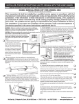
AUB ACSENT UNIVERSAL BLOWER INSTALLATION INSTRUCTIONS ! WARNING ENSURE THE UNIT IS COMPLETELY COOL BEFORE STARTING INSTALLATION TO AVOID DANGER OF SUFFOCATION KEEP THE PACKAGING BAG AWAY FROM BABIES AND CHILDREN. DO NOT USE IN CRIBS, BED, CARRIAGES OR PLAY PENS. THIS BAG IS NOT A TOY. KNOT BEFORE THROWING AWAY. A. Remove the screen by lifting it up and off of the appliance. B. Remove the door from the appliance by releasing the four latches. C. Unplug the control module transformer and lift the control module from the bottom of the appliance, move both the control module and transformer off to one side to ease installation of the blower. D. Install the two clear buttons supplied onto the bottom of the blower bracket to avoid the blower rubbing against the floor of the appliance. E. Remove the two adhesive backing strips from the velcro strips located on the blower bracket. F. Attach the two 1/4” connectors (black and white) from the wire harness to the thermodisc. G. Attach the two 1/4” connectors (black and red) from the wire harness to the blower. H. (For Models B30/B35/B42 ONLY) - Pivot the blower into the bottom of the appliance, center it on the back wall of the outer shell. Press the blower firmly against the outer shell so the adhesive sticks to the appliance. (For Models B36/GX36 ONLY) - Pivot the blower into the bottom of the appliance, press the blower firmly against the left side of outer shell, behind the electrical box, so the adhesive sticks to the appliance. NOTE: ENSURE ALL WIRES REMAIN CLEAR OF THE BLOWER. FIGURE 1 Place the control module back into it’s original position. Ensure the transformer is plugged into the rear outlet of the electrical box, VARIABLE refer to Figure 2, below. SPEED SWITCH I. J. K. The variable speed switch (VSS) will need to be assembled; place the variable speed switch through the mounting bracket using the lock washer to secure it in place. Take the variable speed switch knob and install into position. (Refer to Figure 1.) (VSS) MOUNTING BRACKET LOCK WASHER Remove the adhesive backing strip from the velcro strip located on the variable speed switch (VSS). Place the VSS firmly into position on VSS KNOB the front left corner of the base of the outer shell, refer to Figure 2. Plug the connector from the variable speed switch to the matching connection on the wire harness. FIGURE 2 ELECTRICAL BOX VARIABLE SPEED SWITCH (VSS) BLOWER POWER CORD CONTROL MODULE W415-1372 / B / 01.28.15 :ROI6WHHO/WG1DSROHRQ5G%DUULH21/0*&DQDGD ID[ ZZZQDSROHRQILUHSODFHVFRP L. Position the magnetic thermal disc bracket on the firebox base approximately 4” (101.6mm) from the front of the appliance, refer to Figure 3. Ensure the wire harness is properly attached. M. Plug the power cord from the blower into the electrical box, refer to Figure 2. NOTE: The blower is thermally activated, so when it is turned on, it will automatically start approximately 15 minutes after lighting the appliance and will run for approximately 30 minutes after the appliance has been turned off. FIGURE 3 THERMAL DISK BRACKET 4” (101.6mm) TO VIEW A VIDEO OF THIS INSTALLATION VISIT OUR WEBSITE AT: www.napoleonfireplaces.com/productsupport NOTE: FOR MORE DETAILED INSTRUCTIONS REFER TO YOUR INSTALLATION MANUAL. W415-1372 / B / 01.28.15 :ROI6WHHO/WG1DSROHRQ5G%DUULH21/0*&DQDGD ID[ ZZZQDSROHRQILUHSODFHVFRP AUB INSTRUCTIONS D’INSTALLATION DU SOUFFLERIE UNIVERSEL POUR LA SÉRIE D’ASCENT ! AVERTISSEMENT ASSUREZ-VOUS QUE L’APPAREIL EST COMPLÈTEMENT REFROIDI AVANT DE COMMENCER L’INSTALLATION. AFIN D’ÉVITER LES RISQUES DE SUFFOCATION, GARDEZ LE SAC D’EMBALLAGE LOIN DES BÉBÉS ET DES JEUNES ENFANTS. NE LE LAISSEZ PAS TRAÎNER DANS LES BERCEAUX, LES LITS, LES POUSSETTES OU LES PARCS DE JEU. CE SAC N’EST PAS UN JOUET. NOUEZ-LE AVANT DE LE JETER. A. B. C. D. E. F. G. H. I. J. K. Soulevez le pare-étincelles et enlevez-le de l’appareil. Enlevez la porte de l’appareil en dégageant les quatre loquets. Débranchez le transformateur du module de commande. Soulevez le module de commande du bas de l’appareil, puis déplacez le module et le transformateur sur le côté pour faciliter l’installation de la soufflerie. Installez les deux bouchons claire fourni sur le fond du soufflerie pour éviter le frottement du soufflerie contre le plancher de l’appareil. Enlevez les deux bandes adhésives à l’arrière des bandes en Velcro qui se trouvent sur le support de montage de la soufflerie. Branchez les deux connecteurs de ¼’’ (noir et blanc) du harnais de fils à la soufflerie. Branchez les deux connecteurs de ¼’’ (noir et rouge) du harnais de fils à la soufflerie. (Pour Modèles B30/B35/B42 SEULEMENT) - Faites pivoter la soufflerie dans le bas de l’appareil et centrez-la sur la paroi arrière du caisson extérieur. Pressez fermement la soufflerie contre le caisson extérieur pour que l’adhésif colle bien à l’appareil. (Pour Modèles B36/GX36 SEULEMENT) - Faites pivoter la soufflerie dans le bas de l’appareil et pressez fermement la soufflerie contre le caisson extérieur aux côté gauche, en arrière du boïtier électrique, pour que l’adhésif colle bien à l’appareil. NOTE: VEILLEZ À CE QUE TOUS LES FILS RESTENT ÉLOIGNÉS DE LA SOUFFLERIE. Remettez le module de commande dans sa position originale. FIGURE 1 Assurez-vous que le transformateur est branché dans la prise arrière de la boîte électrique, comme indiqué à la Figure 2. INTERRUPTEUR L’interrupteur à vitesse variable doit être assemblé; placez l’interrupteur À VITESSE à vitesse variable sur le support de montage utilisant le rondelle VARIABLE de bloackage pour le fixer en place. Puis installer le bouton de SUPPORT DE l’interrupteur en place. (Voir Figure 1.) MONTAGE Enlevez la bande adhésive à l’arrière de la bande en Velcro qui se RONDELLE DE BLOCAGE trouve sur l’interrupteur à vitesse variable (IVV). Mettez l’IVV bien en place dans le coin avant gauche de la base du caisson extérieur, BOUTON DE L’INTERRUPTEUR comme indiqué à Figure 2. Branchez le connecteur de l’IVV dans la prise correspondante du harnais de fils. FIGURE 1 BOÎTIER ÉLECTRIQUE CORDON INTERRUPTEUR D’ALIMENTATION À VITESSE DE LA SOUFFLERIE VARIABLE MODULE DE COMMANDE W415-1372 / B / 01.28.15 :ROI6WHHO/WG1DSROHRQ5G%DUULH21/0*&DQDGD ID[ ZZZQDSROHRQILUHSODFHVFRP L. M. Placez le support aimanté du thermodisque sur la base de la chambre de combustion environ à 4” (101,6 mm) du devant de l’appareil, comme indiqué à la Figure 3. Veillez à ce que le harnais de fils soit bien fixé. Branchez le cordon d’alimentation de la soufflerie dans la boîte électrique, comme indiqué à la Figure 2. NOTE: La soufflerie est actionnée par la chaleur. Lorsqu’elle est mise sous tension, elle se met automatiquement en marche environ 15 minutes après l’allumage de l’appareil et fonctionnera environ 30 minutes après l’arrêt de l’appareil. FIGURE 3 SUPPORT DU THERMODISQUE 4” (101.6mm) POUR REGARDER UNE VIDÉO DE CETTE INSTALLATION VISITER NOTRE SITE WEB: www.napoleonfireplaces.com/productsupport NOTE: VOIR LE MANUEL D’INSTRUCTIONS D’INSTALLATION POUR LES INSTRUCTIONS PLUS DÉTAILLÉES W415-1372 / B / 01.28.15 :ROI6WHHO/WG1DSROHRQ5G%DUULH21/0*&DQDGD ID[ ZZZQDSROHRQILUHSODFHVFRP