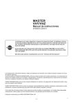
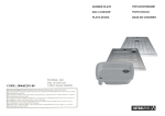
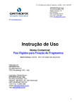
1
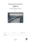
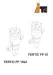
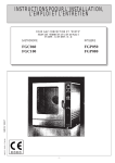
FERTIC
E
GB
F
E
NORMAS DE SEGURIDAD
Para evitar riesgos personales, daños al medio ambiente y garantizar el buen
funcionamiento del equipo, es necesario que el personal encargado de la
instalación, puesta en marcha y mantenimiento del equipo, respete las
instrucciones de este manual con especial atención a las recomendaciones y
advertencias explícitamente detalladas. Además se deberán seguir las
instrucciones específicas reseñadas en los productos químicos a dosificar.
GB
SAFETY RULES
To avoid personal or enviromental damages and to guarantee a proper
operation of the equipment, the staff in charge of the installation, set up and
maintenance of the equipment must follow the instructions of this manual,
specially those recommendations and warnings explicitly detailed. In addition,
specific instructions for the chemical products to be dosed should be followed.
F
NORMES DE SÛRETE
Pour éviter des risques aux personnes, des dégâts à l’environement, et
garantir la bonne marche des appareils, le personnel chargé de l’installation,
la mise en marche et entretien de l’equipement devra respecter les
instructions du manuel prêtant une attention spéciale aux recommandations et
conseils explicités en détail. En outre il faudra suivre les instructions
spécifiques pour l’utilisation des produits chimiques de dosage.
E
ÍNDICE
1.DESCRIPCIÓN
2.CARACTERÍSTICAS TÉCNICAS
3.FUNCIONAMIENTO
4.MONTAJE E INSTALACIÓN
5.DESPIECE
6.MANTENIMIENTO
GB
INDEX
1.DESCRIPTION
2.TECHNICAL FEATURES
3.OPERATION
4.ASSEMBLY AND INSTALLATION
5.LIST OF PARTS
6.MAINTENANCE
F
INDEX
1.DESCRIPTION
2.CARACTÉRISTIQUES TECHNIQUES
3.FONCTIONNEMENT
4.MONTAGE ET INSTALLATION
5.CATALOGUE DES PIECES
6.ENTRETIEN
Página
4
5
6
8-11
12-13-14
17
Page
4
5
6
9-11
12-13-15
18
Page
4
5
6
10-11
12-13-16
19
E
1.DESCRIPCIÓN
La bomba FERTIC es una bomba hidráulica dosificadora de abonos
líquidos o solubles en disolución, para su inyección en el agua de riego.
Es totalmente compacta, sin otros elementos exteriores que las mangueras
de conexión y no produce pérdida de carga en la tubería del agua de riego.
La bomba FERTIC puede automatizarse mediante un programador, que
actuando sobre una electroválvula, abra o cierre el paso del agua de desagüe
GB 1. DESCRIPTION
FERTIC is a hydraulic pump for dosing liquid or soluble fertilizers
dissolution, for their injection into the irrigation system.
It is completely compact, with no other outer elements than the connection
hoses, and it does not cause any pressure loss in the irrigation pipes.
The FERTIC pump can be automated by means of a programmer which acting
on an electrovalve, opens or closes the entrance of the drainage water.
F 1. DESCRIPTION
La pompe FERTIC est un appareil hydraulique qui dose fertilisants
liquides ou solubles in dissolution et les injecte dand l'eau d'arrosage.
Elle est absolument compacte, sans autres éléments extérieurs que les
tuyeaux de connexion et ne produit aucune perte de charge dans la
canalisation de l'eau d'arrosage.
La pompe FERTIC peut être automatisée au moyen d'un programmateur qui,
agissant sur une éléctrovanne, ouvre ou ferme l'ecoulement d'eau.
4
E
2.CARACTERÍSTICAS TÉCNICAS
Capacidad de inyección
: según curva
Presión de trabajo
: 1 - 12 bar (14 - 174 psi)
Consumo de agua
: dos veces la inyección de abono
Material en contacto con el liquido a inyectar : polypropyleno (p.p.) - viton
Resistente a los productos agroquímicos
GB 2.TECHNICAL FEATURES
Injection flow
: see graph
Working pressure
: 1 - 12 bar (14 - 174 psi)
Water consumption
: twice the injection of fertilizer
Materials in contact with the fertilizer: polypropylene (p.p.) - viton
Resistant to agrochemical products
F 2.CARACTERÍSTIQUES TECHNIQUES
Capacite d'injection
: voir le diagramme
Pression de travail
: 1 - 12 bar (14 - 174 psi)
Consommation d'eau
: deux fois le volume de fertilisant injecte
Materiel en contact avec le liquide a injecter :polypropylene (p.p.) - viton
Resistance a les produits agrochimiques
CAUDAL / FLOW / DEBIT
(GPH)
l/h
(132) 500
(119) 450
(106) 400
(92) 350
(79) 300
(66) 250
(53) 200
(40) 150
(26) 100
(13)
50
bar 1
2
3
4
5
6
7
8
9 10 11 12
(PSI) (14) (29) (43) (58) (72) (87) (101) (116) (130) (145) (159) (174)
PRESION / PRESSURE / PRESSION
5
E 3.FUNCIONAMIENTO
3.1 Regulación y dosificación
La bomba dispone en su parte superior de una válvula micrométrica que
regula el paso de abono a inyectar. Con tres o cuatro vueltas se consigue desde
una posición de mínimo a máximo de apertura, por lo que no es aconsejable
accionarla más vueltas.
La Bomba hidráulica FERTIC inyecta 0.2 l/h en cada ciclo
En cada ciclo la bomba da dos golpes en el eje del pistón.
GB 3. OPERATION
3.1 Regulation and dosing
In its upper side the pump has a micrometric valve for the regulation of the
flow of the fertilizer to be injected. By means of three or four turns a minimum to a
maximum opening position can be attained, wherefore it is not advisable to rotate
it more.
The FERTIC hydraulic pump injects 0.2 l/h in every cycle.
In each cycle the pump knocks twice on the piston axis.
F
3.FONCTIONNEMENT
3.1Reglage et dosage
La pompe a dans sa partie supérieure une souppape micrométrique qui
régle le pas du fertilisant qui doit être injecté. Avec trois ou quatre tours on va
d'une position d'ouverture réduite à une position de la plus grande ouverture, par
conséquent on ne conseille pas de l'ouvrir davantage.
La pompe hydraulique FERTIC injecte 0.2 l/h à chaque cycle.
Dans chaque cycle la pompe donne deux coups sur l'axe du piston.
20 l/h
50 l/h
100 l/h
150 l/h
200 l/h
250 l/h
300 l/h
350 l/h
400 l/h
450 l/h
500 l/h
un ciclo cada
one cycle every
un cycle chaque
"
"
"
"
"
"
"
"
"
"
36 seg.
14 seg.
7 seg.
5
3.5
3
2.5
2
6
=
=
=
=
=
=
=
=
=
=
=
1.5
4
8
12
16
21
25
29
33
37
42
ciclos / min.
cycles / min.
cycles / min.
"
"
"
"
"
"
"
"
E
3.2 Diagrama funcionamiento
GB 3.2 Operation diagram
F
3.2 Diagramme fonctionnement
REGULADOR INYECCIÓN
INJECTION REGULATOR
RÉGULATION INJECTE
VÁLVULA
VALVE
CLAPET
CILINDRO
CYLINDER
CYLINDRE
INYECCIÓN
INJECTION
INJECTE
F
DESAGÜE
DRAIN
SORTIE D’EAU
D
C
TOMA DE AGUA
WATER INLET
EAU ENTRÈE
EJE
SHAFT
AXE
VÁLVULA ASPIRACIÓN
SUCTION VALVE
ASPIRATION CLAPET
PISTÓN
PISTON
E
ASPIRACIÓN
SUCTION
ASPIRATION
OK
NO
7
E
4.MONTAJE E INSTALACIÓN
Los soportes especiales de acero inoxidable permiten instalar la bomba
en el suelo, en una superficie plana o bien en la pared.
La bomba FERTIC debe instalarse siempre en la posición que indica el dibujo de
modo que el eje del racord por donde circula el abono estén en posición vertical y
la torreta de regulación en su parte superior.
Con los soportes (66230) se suministran las tuercas M-6 (66334) necesarias para
la instalación. En el montaje en la pared se necesitan seis tuercas. En el suelo
ocho.
Hacer dos tomas en la red de agua donde se desee instalar la bomba (A) y (B)
distante entre ellas 0.25 m como mínimo.
Toma de presion (C) Conectar la manguera flexible de toma de presión (A) en el
racord de la bomba (C) intercalando el filtro de linea de 70
mesh que se sirve.
Inyeccion del abono (F) Del racord de la bomba (F) colocar la manguera flexible
de inyección a la toma de la red de riego (B)
intercalando la válvula antisifón a 0.5m por encima del
nivel de abono como mínimo.
Aspiracion del abono(E) Colocar el filtro de 70 mesh y no aspirar el abono de
la base del tanque.
Desagüe (D)
Conectar la manguera de desagüe libre al exterior o a la
aspiración de la bomba de riego.
F
D
C
E
IMPORTANTE
En la toma de agua (A), inyección de abono (B) y aspiración de abono (E) se
aconseja colocar válvulas de bola de plástico para el mantenimiento de la bomba.
No aspirar el abono del fondo para evitar las partículas no disueltas.
8
GB
4.ASSEMBLY AND INSTALLATION
The special supports of stainless steel (66230) permit the installation of
the pump on the floor, or a flat surface, or on the wall.
The FERTIC pump should always be installed in the position indicated in the
diagram so that the axes of the fertilizer connections are in a vertical position
with the regulation turret above.
The nuts M-6 (66334) necessary for the installation are furnished together with
the supports. In the wall assembly, six nuts are needed, on the floor, eight.
Put two inlets (A) and (B) in the water network where the pump is going to be
located at a minimum distance of 0.25 m. (0.75 ft) from each other.
Pressure inlet (C) Connect the flexible pressure inlet hose (A) to the pump
connector (C) inserting the 70 mesh line filter that is
provided.
Fertilizer injection(F) From the pump connector (F) put the flexible
injection hose at the irrigation network inlet (B) inserting
the antisyphon valve at a minimum of 0.5 m. (1.5 ft)
above the fertilizer level.
Fertilizer suction (E) Place the 70 mesh filter Do not suck up the fertilizer
directly from the tank bottom.
Drainage (D) Connect the free drainage hose to the outside or to the suction of
the irrigation pump.
F
D
E
C
IMPORTANT
It is advisable to put plastic ball valves at the water inlet (A) fertilizer injection
(B) and fertilizer suction (E) for the maintenance of the pump.
Fertilizer should not be sucked from de tank bottom to avoid taking up non
dissolute particles.
9
F
4.MONTAGE ET INSTALLATION
Les supports spéciaux en acier inoxydable permettent l'installation de la
pompe soit au sol (surface plane), soit contre un mur.
La pompe FERTIC sera toujours installée suivant les indications et position
données par l'schéma de montage de façon que les axes des raccords du circuit du
fertilisant se trouvent en position verticale et la tourrelle de régulation à la partie
supérieure de la pompe.
Avec les supports (66230) sont fournis les écrous M-6 (66334) nécessaires au
montage (au sol: 8 écrous) - (au mur : 6 ecrous)
Il faut faire deux prises d'eau (A) et (B) dans le réseau où la pompe doit être
installée, à une distance d'au moins 0.25 m. entre elles.
Prise de pression(C) Joindre le tube flexible de prise de pression au raccord de
la pompe © insérant le filtre de ligne de 70 mesh.
Injection de fertilisant (F) Du raccord de la pompe (F) brancher le tube flexible
d'injection à la prise du réseau d'arrosage (B).Intercaler la
soupape anti-siphon à 0.5 m au-dessus du niveau du
fertilisant.
Aspiration du fertilisant (E) Il faut placer le filtre à ligne de 70 mesh.
Écoulement (D) Brancher le tuyeau d'issue libre à l'extérieur ou à
l'aspiration de la pompe d'arrosage.
F
D
C
E
IMPORTANT
On conseille de placer des vannes à boule en plastique dans la pris d'eau (A),
injection de fertilisant (B), et aspiration de fertilisant (E), pour l'entretien de la
pompe.
Ne pas aspirer le fertilisant du fond pour éviter les particules non dissoutes.
10
INSTALACIÓN / INSTALLATION
min. 0.5m
F
Desagüe
Drain
Sortie d’eau
D
C
E
min.5 cm
8 9 10
11
7
6
12
5
4
32
1
A
B
Válvula antisifón
Antisyphone valve
Soupape anti-siphon
F
Filtro
Filter
Filtre
Válvula
Valve
Vanne
8 910
11
7
6
12
5
4
32
1
D
C
Manómetro
Manometer
Manomètre
E
Collarin de toma
Connector clamp
Collier de prise
11
5.DESPIECE / LIST OF PARTS / CATALOGUE DES PIECES
FERTIC
66210
66328
66-005
66220
66204
66-018
66477
66407
66403
(3x)66334
66403
(6x) 66344
(6x)66334
(6x) 66209
(6x) 66344
(6x) 66334
(3x) 66334
66230
66230
12
66-001
66227
66206
(PN)66212
66207
66206
66161
(PN)66212
66308
66-002
(4x) 66318
66163
66205
66401
66171
66224
66427
66172-P
66333
66-015
(PN)66-014
(4x) 66111
(4x) 66347
(4x) 66112
(PN)66213
(4x) 66128
(7x) 66401
66122
66-011
66333
66226
66224
66170
66327
66433
66345
66214
66301
66146
66113
66-801
65141
66401
66171
13
E 5.DESPIECE
Código
65141
66111
66112
66113
66122
66128
66146
66161
66163
66170
66171
66172-P
66204
66205
66206
66207
66209
66210
66212
66213
66214
66220
66224
66226
66227
66230
66301
66308
66318
66327
66328
66333
66334
66344
66345
66347
66401
66403
66407
66427
66433
66477
Conjuntos
66-001
66-002
66-005
66-011
66-014
66-015
66-018
66-801
Descripción
Tapón M12
Tapón leva Fertic latón
Muelle 8,5x30x0,9
Tapón motor hidráulico
Tapón M8 latón
Leva retención Fertic
Junta plana 23,5x15x3,5 (silicona)
Regulador torreta
Cuerpo torreta
Racord aspiración 1/2
Racord impulsión 1/2
Anillo válvula retención tórica
Pistón Fertic
Eje Fertic
Muelle 11x66,5x1,4
Tope muelle eje Fertic
Varilla M6x279 Fertic
Tapa cilindro Fertic
Muelle Fertic PN 67,3x1,2x11
Muelle Fertic PN 25x8,5x0,9
Tope eje Fertic
Pasador pistón Fertic
Bola 11mm sódico cálcico
Cuerpo válvula retención
Tapón 3/8' x 15
Soporte Fertic
Junta tórica 22x1,5 NBR
Junta tórica 7 x 2 FPM
Tornillo philips M4x5 Din 7985
Junta tórica 100x2 NBR
Junta tórica 80x2 NBR
Junta tórica 14x3 NBR
Tuerca M6 Din 934 A2
Arandela D6 Din 125 A2
Junta plana 17x24x2 NBR
Junta tórica 8x1,6 NBR
Junta tórica 15x2,5 NBR
Collarín Fertic 88x100x8,3 NBR
Collarín 68x80x8,3 NBR deM8068
Junta tórica 10x1,5 FPM
Junta tórica 6x2,5 NBR
Collarín 68x80x8,3 FPM
Eje Fertic
Torreta de regulacion completa
Pistón Fertic completo
Válvula Fertic PMMA completa
Cilindro Fertic PN completo
Cilindro Fertic completo
Kit juego collarines Fertic
Válvula aspiración PP
14
Cantidad
2
4
4
1
2
4
1
1
1
1
3
1
1
1
2
2
6
1
2
4
1
1
2
1
1
2
1
1
4
1
1
2
18
12
1
4
10
2
1
1
2
1
1
1
1
1
1
1
1
1
GB 5.LIST OF PARTS
Code
65141
66111
66112
66113
66122
66128
66146
66161
66163
66170
66171
66172-P
66204
66205
66206
66207
66209
66210
66212
66213
66214
66220
66224
66226
66227
66230
66301
66308
66318
66327
66328
66333
66334
66344
66345
66347
66401
66403
66407
66427
66433
66477
Assembly
66-001
66-002
66-005
66-011
66-014
66-015
66-018
66-801
Description
Cam plug M12 Ecofertic
Retention cam plug
Spring 8,5x30x0,9
Hydraulic motor plug
M8 plug
Retention cam Ecofertic
Flat seal 23,5x15x3,5 silicone
Regulation turret
Regulation turret body
Suction connector , 1/2"
Impulsion connector 1/2
Ring for check valve w. o-ring PP
Piston fertic
Shaft Fertic
Spring 11x66,5x1,4
Shaft spring stopper Fertic
Screw rod M6x280
Cylinder lid
Spring Fertic PN 67,3x1,2x11
Spring Fertic PN 25x8,5x0,9
Shaft bumper Fertic
Piston bolt Fertic
Ball 11mm soda lime
Retention valve body
Shaft plug 3/8
Support Fertic
O-ring 22x1,5 NBR
O-ring 7 x 2 FPM
Screw M4x5 Din 7985
O-ring 100x2 NBR
O-ring 80x2 NBR
O-ring 14x3 NBR
Nut M6 Din 934 A2
Washer D6 Din 125 A2
Flat seal 17x24x2 NBR
O-ring 8x1,6 NBR
O-ring 15x2,5 NBR
Seal 88x100x8,3 NBR Fertic
Seal 68x80x8,3 NBR deM8068
O-ring 10x1,5 FPM
O-ring 6x2,5 NBR
Seal 68x80x8,3 FPM
Shaft Fertic assembly
Regulation turret assembly
Piston fertic assembly
Valve PMMA Fertic assembly
Cylinder Fertic PN assembly
Cylinder Fertic assembly
Seals set Fertic
Suction Valve 1/2 PP
15
Units
2
4
4
1
2
4
1
1
1
1
3
1
1
1
2
2
6
1
2
4
1
1
2
1
1
2
1
1
4
1
1
2
18
12
1
4
10
2
1
1
2
1
1
1
1
1
1
1
1
1
F 5.CATALOGUE DES PIECES
Code
Description
65141
Bouchon M12 Ecofertic
66111
Came Bouchon Fertic
66112
Ressort 8,5x30x0,9
66113
Bouchon moteur
66122
Bouchon M8
66128
Rétention came Ecofertic
66146
Jointt plat bouchon 23,5x15x3,5
66161
Vanne tourrelle
66163
Corps tourrelle
66170
Racord aspiracion 1/2"
66171
Racord impulseur 1/2
66172-P
Anneau clapet
66204
Piston Fertic
66205
Axe Fertic
66206
Ressort 11x66,5x1,4
66207
Rodelle ressort Fertic
66209
Goujon flete M6x280
66210
Couvercle cylindre
66212
Ressort Fertic PN 67,3x1,2x11
66213
Ressort Fertic PN 25x8,5x0,9
66214
Bouchon axe
66220
Goupille piston
66224
Bille pirex 11mm
66226
Corps clapet
66227
Shaft Bouchon 3/8
66230
Support Fertic
66301
Joint torique 22x1,5 NBR
66308
Joint torique 7 x 2 FPM
66318
Vis M4x5 Din 7985
66327
Joint torique 100x2 NBR
66328
Joint torique 80x2 NBR
66333
Joint torique 14x3 NBR
66334
Ecron M6 Din 934 A2
66344
Rondelle D6 Din 125 A2
66345
Joint plat 17x24x2 NBR
66347
Joint torique 8x1,6 NBR
66401
Joint torique 15x2,5 NBR
66403
Joint alévre 88x100x8,3 NBR Fertic
66407
Joint alévre 68x80x8,3 NBR deM8068
66427
Joint torique 10x1,5 FPM
66433
Joint torique 6x2,5 NBR
66477
Joint alévre 68x80x8,3 FPM
Ensemble
66-001
Axe Fertic ensemble
66-002
Tourrelle regulateur ensemble
66-005
Piston Fertic ensemble
66-011
Clapet PMMA Fertic ensemble
66-014
Cylindre Fertic PN ensemble
66-015
Cylinder Fertic ensemble
66-018
Jeu joint alévre Fertic
66-801
Aspiration clapet 1/2 PP
16
Unité
2
4
4
1
2
4
1
1
1
1
3
1
1
1
2
2
6
1
2
4
1
1
2
1
1
2
1
1
4
1
1
2
18
12
1
4
10
2
1
1
2
1
1
1
1
1
1
1
1
1
E
6.MANTENIMIENTO
Limpiar los filtros de aspiración de abono y toma de presión al final de cada
campaña, o si se inyectan líquidos muy agrsivos o precipitables.
Limpiar la bomba inyectando agua limpia a través de la bomba a la red de
riego.
PROBLEMA
CAUSA
LA BOMBA FUNCIONA PERO NO
INYECTA
VÁLVULA DE ABONO CERRADA
ABRIRLA
FILTRO DE ABONO SUCIO
LIMPIARLA
VÁLVULAS DE RETENCIÓN DE ASPIRACIÓN O IMPULSIÓN SUCIAS O
DETERIORADAS
DESMONTARLAS Y LIMPIARLAS O COMBIARLAS
VOLVIÉNDOLAS A MONTAR COMO INDICA EL
DIBUJO DE DESPIECE
COLLARÍN DESGASTADO
CAMBIARLO (C)
COLLARÍN DESGASTADO
CAMBIARLO (C)
CILINDRO RAYADO
LLAMAR AL SERVICIO
TÉCNICO
VÁLVULAS DE ASPIRACIÓN DE ABONO, INYECCIÓN, TOMA DE PRESIÓN
O TORRETA DE REGULACIÓN CE RRADAS
ABRIRLAS
FALTA DE PRESIÓN DE AGUA
PRESIÓN DE TRABAJO DE
1 A 12 BAR (Atm.)
DESAGÜE OBTURADO
DESATASCARLO
NIVEL DE DESAGÜE SUPERIOR AL
DE LA BOMBA
LA BOMBA NO PUEDE TENER EL NIVEL DE DESAGÜE
POR ENCIMA DEL NIVEL DE
LA BOMBA
LA BOMBA DESAGUA MÁS DE
LO NORMAL
COLLARINES DESGASTADOS
CAMBIARLO (C)
LA BOMBA FUNCIONA MÁS
LENTA DE LO NORMAL
TORRETA DE REGULACIÓN O VÁLVULAS DE FUNCIONAMIENTO CASI
CERRADAS
ABRIRLAS
FILTROS SUCIOS
LIMPIARLO
LA BOMBA PIERDE ABONO POR
EL DESAGÜE
LA BOMBA NO FUNCIONA
17
SOLUCIÓN
GB 6.MAINTENANCE
Clean the fertilizer suction and pressure inlet filters.
At the end of season, or if very aggressive or precipitable liquids have been
injected, the pump must be cleaned by injecting clean water thought the pump to
the irrigation network.
PROBLEM
THE PUMP WORKS BUT
DOES NOT INJECT
FERTILIZER IS LOST
THROUGH THE OUTLET
CAUSE
SOLUTION
IRRIGATION VALVE CLOSED
OPEN IT
DIRTY FERTILIZER FILTER
CLEAN IT
SUCTION OR IMPULSION
RETENTION VALVES DIRTY OR
DAMAGED
THEY MUST BE
DISASSEMBLED AND
CLEANED OR CHANGED,
AND ASSEMBLED AGAIN AS
INDICATED IN THE FIGURE
COLLAR WORN OUT
CHANGE IT
COLLAR WORN OUT
CHANGE IT
CYLINDER DAMAGED
FERTILIZER SUCTION, INJECTION,
PRESSURE INLET OR
REGULATION TURRET VALVES
CLOSED
OPEN THEM
LACK OF WATER PRESSURE
WORKING PRESSURE 1TO
12 BAR 14 TO174PSI
DRAINAGE CLOSET
UNBLOC IT
DRAINAGE LEVEL HIGHER THAT
THE PUMP
DRAINAGE LEVEL CAN NOT
BE ABOVE THE PUMP LEVE
PUMP DRAINS IN EXCESS
COLLAR WORN OUT
CHANGE THEM
PUMP WORKS MORE
SLOWLY THAN USUAL
REGULATION TURRET OR
WORKING VALVES ALMOST
CLOSED
OPEN THEM
DIRTY FILTERS
CLEAN THEM
THE PUMP DOES NOT
WORK
18
F
6.ENTRETIEN
Nettoyer les filtres d'aspiration de fertilisant et prise de pression.
A la fin de la saison, ou si des liquides très agressifs ou precipitables ont été
injectés, il faut nettoyer la pompe en injectant de l'eau propre à travers de la pompe
au reseau d'arrosage.
PROBLÈME
LA POMPE TRAVAILLE MAIS
ELLE N'INJECTE PAS
LA POMPE PERD
FERTILISANT PAR LA
SORTIE D'EAU
LA POMPE NE FONCTIONNE
PAS
LA POMPE PERD PLUS
D'EAU QUE D'HABITUDE
LA POMPE MARCHE PLUS
LENTEMENT QUE
D'HABITUDE
CAUSE
SOLUTION
LA VANNE DU FERTILISANT EST
FERMÉE.
OUVRIR
LE FILTRE DU FERTILISANT EST
SALE
NETTOYER
CLAPETS D'ASPIRATION OU
D'INJECTION SALES OU
DETERIORES.
DEMONTER LES CLAPETS
ET NETTOYER OUR
CHANGER. MONTER
D’ACCORD AVEC LE PLAN
DE MONTATGE
JOINTS A LEVRES USÉ.
CHANGER
JOINTS A LEVRES USÉ.
CHANGER
CYLINDRE USÉ
VANNES D'ASPIRATION DE
FERTILISANT, INJECTION,
PRISE DE PRESSION OU
TOURELLE DE REGULATION,
FERMÉES
OUVRIR
MANQUE DE PRESSION D'EAU
PRESSION DE TRAVAIL 1 Á
12 BAR (14 Á 174PSI)
SORTIE D'EAU OBSTRUÉE
DÉBOUCHER
NIVEAU DE SORTIE PLUS HAUT
QUE LA POMPE
LE NIVEAU DE SORTIE
D’EAU NE DOIT PAS ÊTRE
PLUS HAUT QUE LE NIVEAU
DE LA POMPE
JOINTS A LEVRES UsÉ.
CHANGER
TOURRELLE DE RÉGULATION OU
VANNES DE FONCTIONNEMENT
PRESQUE FERMÉES
OUVRIR
FILTRES SALES
NETTOYER
19
E
DECLARACIÓN CE DE CONFORMIDAD
I.T.C S.L..
Mar Adràtic, 1
Polígono Torre del Rector
08130 Santa Perpètua de Mogoda
Declara que todos los modelos de los productos FERTIC, identificados con
número de serie y año de fabricación, cumplen la Directiva de Máquinas 98/37/CE
siempre que la instalación, el uso y el mantenimientos se efectúen de acuerdo con
la normativa vigente y siguiendo las indicaciones del manual de instrucciones.
GARANTÍA
Antón Planas
Gerente
I.T.C. S.L. garantiza el producto especificado en este documento por el
periodo de 1 año a partir de la fecha de compra, contra todo defecto de
fabricación o material, siempre que la instalación, uso y mantenimiento del
equipo hayan sido los correctos.
El equipo debe ser remitido, libre de gastos, a nuestro taller o servicio
técnico de I.T.C. S.L. acreditado y su devolución será efectuada a portes
debidos.
Deberá acompañar al equipo el documento de garantía con la fecha de
compra y sello del establecimiento vendedor, o fotocopia de la factura de
compra.
MODELO
Fecha de compra y sello del
establecimiento vendedor
Nº SERIE
FECHA:
20
GB
EC CONFORMITY DECLARATION
I.T.C S.L..
Mar Adriàtic, 1
Polígono Torre del Rector
08130 Santa Perpètua de Mogoda
Declares that all models of FERTIC products, identified by a serial number and year
of manufacture, strictly fulfill 98/37/CE Governing Body, as long as installation, use
and maintenance are carried out following the prevailing regulation and following the
instructions contained in the handbook.
WARRANTY
Antóm Planas
Manager
I.T.C. S.L. Warrants the product specified in this document for a period of 1
year from the purchase date. This warranty obligation is limited to the free
replacement of the damaged parts due to any material or manufacture
defect. This warranty does not include periodic maintenance and damage
resulting from misuse.
The equipment must be sent to I.T.C. S.L. Service Center with prepaid
transport charges, and will be sent back with transport charges for
customer’s account.
The warranty document with sales date and shop stamp, or an invoice
copy must be sent with the equipment.
MODEL
Sales date and shop stamp
SERIAL #
DATE: ________________
21
F
DÉCLARATION CE DE CONFORMITÉ
I.T.C S.L..
Mar Adriàtic, 1
Polígono Torre del Rector
08130 Santa Perpètua de Mogoda
On déclare que tous les modèles des produits FERTIC, portant un numéro de série et
l'année de fabrication, accomplissent les Directives de Machines 98/37/CE, pourvue
que l'installation, l'utilisation et l'entretien se fassent d'accord avec les normes en
vigueur et suivant les indications du manuel d'instructions.
GARANTIE
Antón Planas
Directeur Général
I.T.C. S.L. Garantit le produit décrit dans ce document pour la durée d’un
an dès la date d’achat, contre tout défaut de fabrication ou de matériel,
pourvu que l’installation, l’utilisation et l’entretien de l’appareil aient été
corrects.
L’appareil devra être envoyé sans frais à notre usine ou au service
technique officiel de l’ I.T.C. S.L. et il sera renvoyé à port après la
réparation.
L’appareil devra être accompagné par un document de garantie avec la
date d’achat et le cachet de l’établissement de vente, ou photocopie de la
factura de compra.
MODÈLE
Date d’achat et cachet de
l’établissement de vente
NO. DE SÉRIE
DATE:
22
Ed: 26/01/10 ES. AN. FR.
C/ Maresme s/n Pol. Ind. Urvasa
P.O. Box 60
08130 STA. PERPETUA DE MOGODA
BARCELONA - SPAIN
Tel. 935 44 30 40
e-mail: [email protected]
Fax 935 544 31 61
www.itc.es