1
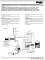
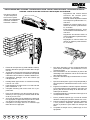
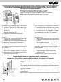
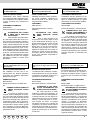
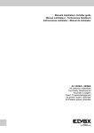
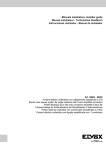
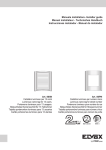
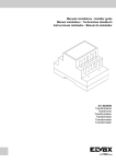
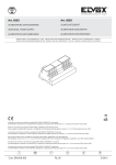
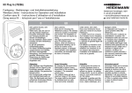
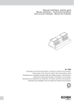
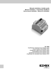
Manuale installatore- Installer guide Manuel installateur - Technisches Handbuch Instrucciones instalador - Manual do instalador Art. 884G/S - 884H/S Kit citofonico monofamiliare One-family interphone kit Kit poste 1 usager Einfamilienhaus-Türsprechanlagenset Kit portero autom. unifamiliar Kit Porteiro autom. unifamiliar SCHEMA COLLEGAMENTO PORTIERE ELETTRICO UNIFAMILIARE KIT ART. 884G/S - 884H/S WIRING DIAGRAM FOR ELECTRIC DOOR-OPENER SYSTEM FOR SINGLE RESIDENCE KIT ART. 884G/S - 884H/S SCHÉMA DES CONNEXIONS PORTIER ÉLECTRIQUE POUR VILLA KIT ART. 884G/S - 884H/S SCHALTPLAN FÜR EINFAMILIENHAUS-TÜRSPRECHANLAGE SET ART. 884G/S - 884H/S ESQUEMA DE CONEXIONADO PORTERO ELÉCTRICO UNIFAMILIAR KIT ART. 884G/S - 884H/S ESQUEMA DE LIGAÇÃO DO PORTEIRO ELÉCTRICO UNIFAMILIAR KIT ART. 884G/S - 884H/S Collegamento solo audio: utilizzare solo due conduttori da 0,65 mm2 fino a 150m. Audio connection only: use two 0.65mm2 fino a 150m. of distance. Connexion phonie uniquement: utiliser deux câbles de 0,65mm2 jusqu’à 150 m. Anschluß der Sprechverbindung: verwenden Sie zwei Drahte mit 0,65 mm2 Querschnitt, bis max. 150m. Instalación de audio solamente: utilizar dos conductore de 0,65 mm2 hasta 150m. Ligação sómente do audio: utilizar dois conductores de 0,65mm2 até 150m. Collegamento audio e serratura: utilizzare cavo da 1 mm2 fino a 50m. Audio and lock connection: use two 1mm2 fino a 50m. of distance. Connexion phonie uniquement: utiliser deux câbles de 1mm2 jusqu’à 50 m. Anschluß der Sprechverbindung und des Türöffner: verwenden Sie Draht mit 1 mm2 Querschnitt, bis max. 50m. Instalación de audio y cerradura: utilizar cable de 1 mm2 hasta 50m. Ligação sómente do audio e trinco: utilizar conductores de 1mm2 até 50m. N. SI573 Art. 8874 Art. 930B 1 2 3 4 2 3 5 6 Ripetitore di chiamata Call repeater Répétiteur d’appel Lautsprecher für Rufverdoppelung Repetidor de llamada Repetidor de chamada Art. 0002/841.05 1 2 3 5 6 7 Art. 8911 P1 O 12 Art. M832 R RETE-NETWORK RÉSEAU-NETZ RED-REDE 2 Serratura Lock Gâche Türöffner Cerradura Trinco 12V ~ PRI PT ES DE FR EN IT INSTALLAZIONE DEL CITOFONO - PHONE INSTALLATION - INSTALLATION DU POSTE - HAUSTELEFON INSTALLIERUNG - INSTALACION DO TELÉFONO- INSTALAÇÃO DO TELEFONE Regolazione del volume esterno all’interno del citofono potenziometro: P1, 470 Ohm. External volume adjustement inside the interphone potentiometer: P1, 470 Ohm. Réglage du volume externe à l’intérieur du combiné: potentiomètre: P1, 470 Ohm. Externlautstärkeregelung innen im Haustelefon Potentiometer: P1, 470 Ohm. Regulación del volumen externo a l’interior del teléfono potenciómetro: P1, 470 Ohm. Regulação do volume externo ao interior do telefone potenciómetro: P1, 470 Ohm. Per aprire il citofono To open interphone Pour ouvrir le poste Öffnen des Haustelefone Para abrir el teléfono Para abrir o telefono Fissare la vite superiore (A) nella scatola incasso (o tassello) lasciando sporgere la testa della vite per 2-3 mm. Agganciare il citofono alla vite superiore utilizzando l’apposito foro posteriore accostandolo alla parete e tirandolo verso il basso in direzione delle frecce. Completare il fissaggio con la vite inferiore (B) nell’apposito foro. 1 Partially fasten upper screw “A” to back box leaving it out for 2 or 3 mm. Hook interphone to upper screw “A” in rear hole and pull it downwards. 1 - 2 Complete mounting with lower screw “B” in prepared hole. 1 1 Fixer la vis supérieure (A) dans la boîte de raccordement (ou vis à goujon) en laissant saillir la tête de la vis pour 2-3 mm. 2 Accrocher le poste à la vis supérieure en utilisant le trou approprié, le rapprocher à la paroi et en le tirant vers le bas en suivant la direction des flèches. 3 Completer le montage avec la vis inférieure (B) fixée dans le trou approprié. 3 1 2 3 1 2 3 IT EN FR DE ES PT 2 3 2 Die obere Schraube (A) am Unterputz-Gehäuse (oder Dübel) befestigen. Die Schraube 2-3 mm vorstehen lassen. Das Haustelefon an der Schraube (A) durch das rückseitige Lock zuhacken und es nach unten laut dem Zeichen ziehen. Die untere Schraube (B) im bestimmten Loch befestigen. Fijar el tornillo superior (A) en la caja empotrada (o taco) dejando la cabeza del tornillo unos 2-3 mm fuera. Enganchar el teléfono al tornillo superior utilizando el correspondiente orificio posterior; acercarlo a la pared y tirar de él hacia abajo en la dirección ilustradas por las flechas. Completar la fijación con el tornillo inferior (B) en el correspondiente orificio. 1 Fixar o parafuso superior (A) no local de encaixe deixando a cabeça do parafuso saliente 2 a 3 mm. 2 Prender o telefone ao parafuso superior, utilizando o furo posterior adequado, aproximando-o da parede e puxando-o para baixo na direcção da seta. 3 Completar a fixação com o parafuso (B) no furo apropriado. 3 INSTALLAZIONE DELLE TARGHE - MOUNTING INSTRUCTIONS OF ENTRANCE PANEL - INSTALLATION DE LA PLAQUE DE RUE -MONTAGEHINWEISE FÜR TÜRSPRECHSTELLE - INSTALACION DE LA PLACA EXTERNA INSTALAÇÃO DA BOTONEIRA EXTERIOR Montare la targa esterna su scatola rettangolare o con tasselli. Fix door panel on rectangular box or with expansion screws. Installer la plaque de rue sur boîte rectangulaire ou avec vis à goujouns. Klingeltableau an der Wand mit Schrauben und Dübel montieren. Montar la tarjeta externa sobre la caja rectangular o con cuñas. Montar a botoneira através de parafusos. Per separare la placca dalla scatola da incasso eseguire le seguenti operazioni: 1: Allentare la vite posta sul bordo inferiore della placca fino a fine corsa a mezzo della chiavetta in dotazione. 2: Allontanare di 2 cm. il bordo inferiore della placca tenendola spinta verso l’alto. 3-4:Togliere la placca tirandola verso il basso. Un die Frontplatte vom Up-gehäuse zu entfernen, gehen Sie wie folgt vor: 1: Schraube am unteren Profilrand bis zum Anschlag mit vergesehenem Schlüssel aufdrehen. 2: Das Profil unten um 2 cm. abheben, die Frontplatte nach oben schieben und ausrasten. 3-4:Frontplatte nach unten ziehen und abhehmen. To separe front plate from back box, follow there instructions: 1: Loosen screw in lower border of front plate to limit of thread, using special key provided. 2: Lift lower border of front plate slightly out wards and upwards. 3-4:Detach front plate by pulling it downwards. Para separar le placa desde la caja de empotre seguir estas operaciones. 1: Aflojar el tornillo puesto sobre el borde inferior de la placa hasta el final del filete con la llave especial provista. 2: Alejar de 2 cm. la orilla inferior de la placa teniéndola empujada hacia arriba. 3-4:Separar la placa jalàndola hacia abajo. Pour séparer la plaque de la boîte à encastrer suivre Para separar a placa botoneira da caixa, seguir as seces opérations: guintes operações: 1: Desserer la vis placée sur le bord inférieur de la 1: Desapertar o parafuso da parte inferior da placa plaque jusq’à la butée en utilisant la clé spéciale até ao fim através de chave especial junta. fournie dans l’emballage. 2: Afastar 2 cm. a parte inferior da placa mantendo-a 2: Soulever de 2 cm le bord inférieur de la plaque en encostada no topo. la tenant poussée vers le haut. 3-4:Separar a placa puxando-a baixo e reteira-la. 3-4:Enlever la plaque en la tirant vers le bas. ESTRAZIONE DEL CARTELLINO PORTANOME-NAME - TAG REMOVING EXTRACTION DE L’ÉTIQUETTE PORTE - NOMS-HERAUSZIEHEN DES NAMENSSCHIELD ESTRACCIÓN DE LA TARJETITA PORTANOMBRES - EXTRAÇÃO DO CARTÃO PORTA-NOMES Per accedere al cartellino portanomi togliere il fermacartellino dal retro come mostra la figura. To reach name-tag, remove name-tag holder from the back, as shown. Pour acceder à l’étiquette porte-noms enlever le porte-étiquette de la partie postérieure comme le montre la figure. Um das Namensschild zu erhalten, entfernen Sie die Namenschildhalterung von der Rückseite, wie dezeigt. Para acceder a la tarjetita portanombres mover el sujetatarjetita desde atrás como muestra la figura. Para ter acesso ao cartão porta-nomes extrair a tampa de plástico que o prende como mostra a figura. 4 PT ES DE FR EN IT INSTALLAZIONE DEGLI ALIMENTATORI - POWER SUPPLY INSTALLATION INSTALLATION DES ALIMENTATIONS - INSTALLATION DER NETZGERÄTE INSTALACIÓN DE LOS ALIMENTADORES - INSTALACIÓN DE LOS ALIMENTADORES INSTALLAZIONE DEGLI ALIMENTATORI L’alimentatore andrà posto in un luogo asciutto e lontano da polvere e fonti di calore. Al fine di facilitare controlli e messe a punto curare che il luogo sia facilmente accessibile. Fissare a parete l’alimentatore mediante i tasselli in dotazione o inserendolo in apposito quadro con barra DIN ad omega. Per una maggiore sicurezza dell’utente, tutte le apparecchiature funzionano in bassa tensione e sono separate dalla rete da un trasformatore ad alto isolamento. È opportuno comunque interporre tra la rete di alimentazione e l’apparecchio un interruttore magnetotermico di portata adeguata. I prodotti sono conformi al marchio CE e alle direttive: - Alla direttiva europea 2004/108/CE e successive. - Alla direttiva europea 2006/95/CE. Gli alimentatori costituiscono una sorgente SELV rispettando i requisiti previsti dall’articolo 411.1.2.2 della norma CEI 64-8 (ed. 2007). La produzione del trasformatore è sotto costante sorveglianza: INSTALLATION DES ALIMENTATIONS L’alimentation devra être placée dans un endroit sec, à l’abri de la poussière et loin de toute source de chaleur. Afin de faciliter les contrôles et les mises au point, choisir un endroit facilement accessible. Fixer l’alimentation sur le mur à l’aide des chevilles fournies de série ou en l’insérant dans un tableau approprié avec barre DIN en oméga. Pour une plus grande sécurité de l’utilisateur, tous les appareils fonctionnent en basse tension et sont séparés du réseau par un transformateur à haute isolation. Il convient dans tous les cas d’interposer un disjoncteur magnétothermique d’une portée appropriée entre le réseau d’alimentation et l’appareil. Les produits sont conformes à la marque CE et à les directives : - À la directive européenne 2004/108/CE et suivantes. - À la directive européenne 2006/95/CE. Les alimentations constituent une source SELV et respectent les qualités requises par l’article 411.1.2.2 de la norme CEI 64-8 (ed. 2007). La production du transformateur est sous constante surveillance: FR Power supply units constitute SELV sources in compliance with the requirements stipulated in Article 411.1.2.2 of CEI standard 64-8 (ed. 2007). Production of the transformer is subject to costant surveillance: INSTALLATION DER NETZGERÄTE Das Netzgerät ist an einem trockenen und staubfreien Ort unter Vermeidung der Nähe von Wärmequellen zu installieren. Zur Erleichterung von Kontrollen und Einstellungen sollte der Aufstellungsort gut zugänglich sein. Das Netzgerät mit den beigepackten Dübeln an der Wand befestigen oder in einen Verteiler mit DIN-Omegaschiene einsetzen. Zur größeren Sicherheit des Anwenders werden alle Apparate mit Niederspannung betrieben und durch einen stark isolierenden Transformator vom Stromnetz getrennt. In jedem Fall sollte jedoch zwischen dem Stromnetz und der Anlage ein Fehlerstromschutzschalter von angemessener Stromfestigkeit installiert werden. Die Produkte sind konform zu den CE-Markenzeichen und Richtlinien: - zu den EG-Richtlinien 2004/108/EG und Folgenden - zu den EG-Richtlinien 2006/95/EG. Die Netzgeräte, die die vom Art. 411.1.2.2 der CEI 64-8 (Ausgabe 2007) norm Vorgesehene fähigkeiten respektieren, eine SELV quelle bestellen. Die Transformatorserzeugung ist unter ständiger Aufsicht: D VE D VE EN Product is according to CE mark and directives: - EC Directives 2004/108/EC and following norms. - EC Directives 2006/95/EC. D VE D VE IT POWER SUPPLY INSTALLATION The power supply must be installed in a dry place away from direct heat or dust. Ensure easy access for inspection and maintenance. Secure the unit to the wall with the anchor bolts provided or insert it into a rack with a omega DIN bar. For user safety, the equipment operates at a low voltage and is separated from the mains by a high-insulation transformer. We recommend installation of an overload cutout of appropriate capacity between the mains and the unit. DE ES PT 5 INSTALACIÓN DE LOS ALIMENTADORES El alimentador tiene que ser colocado en un lugar seco y lejos del polvo y fuentes de calor. Al fin de facilitar controles y puestas a punto el lugar de la instalación debe ser fácilmente accesible. Fijar a la pared el alimentador por medio de tacos en dotación o insertándolo en un cuadro apropiado con barra DIN a omega. Para una mayor seguridad del usuario, todas los aparatos funcionan a baja tensión y son separados de la red por un transformador a alta isolación. Es oportuno de todas maneras poner entre la red de alimentación y el aparato un interruptor magnetotérmico de portada adecuada. INSTALAÇÃO DOS ALIMENTADORES O alimentador deverá ser colocado num local seco e ao abrigo do pó e de fontes de calor. Para facilitar os controlos e as afinações, certifique-se de que o local é de fácil acesso. Fixe o alimentador à parede com as buchas fornecidas ou inserindo-o num quadro próprio com calha DIN tipo omega. Para uma maior segurança do utilizador, todos os aparelhos funcionam em baixa tensão e estão separados da rede por um transformador de alto isolamento. Em todo o caso, convém colocar entre a rede de alimentação e o aparelho um interruptor magnetotérmico de capacidade adequada. Los productos son conformes a la marca CE y a las normas : - A las normas europeas 2004/108/CE y siguientes - A las normas europeas 2006/95/CE. Os produtos estão em conformidade com a marca CE e as directivas: - Directiva europeia 2004/108/CE e seguintes. - Directiva europeia 2006/95/CE. Los alimentadores constituyen una fuente SELV y respectan los requisitos previstos por el artículo 411.1.2.2 de la norma CEI 64-8 (ed. 2007). Os alimentadores constituem uma fonte SELV e cumprem os requisitos previstos no artigo 411.1.2.2 da norma CEI 64-8 (ed. 2007). A fabrico do transformador está sob a constante vigilância de: A produção do transformador está sob vigilância constante: D VE D VE USO - OPERATION - MODE D’EMPLOI - FUNKTION - UTILIZAÇÃO Eseguire la chiamata dall’esterno premendo il pulsante della targa e parlare a mani libere dopo aver ricevuto la risposta. Make calls by pushing door panel button and talk handsfree after receiving reply. Appeler en appuyant sur le bouton-poussoir de la plaque de rue et parler mains libres après avoir reçu la réponse. Herstellung des Rufes durch Betätigung des Klingeltasters. LLamar desde el exterior apretando el pulsador de la tarjeta y hablar a manos libres después de haber recibido la respuesta. Efectuar a chamada do exterior premindo o botão da botoneira e falar a mãos livres depois de receber a resposta. 6 All’interno sollevare il microtelefono ed incominciare a parlare. Premere l’apposito pulsante per azionare la serratura elettrica. Answer calls by lifting phone handset. Operate electric lock by pushing appropriate button. Pour répondre aux appels soulever le combiné du poste d’appartement, la gâche électrique est commandée par le bouton approprié. Nach Abheben des Haustelefons ist die Gesprächsverbindung hergestellt. Türöffner durch entsprechende Taste betätigen. En el interior, levantar el microteléfono y comenzar a hablar. Apretar el pulsador apropiado para accionar la cerradura eléctrica. No interior levantar o telefone e começar a falar. Premir o botão respectivo para accionar o trinco eléctrico. PT ES DE FR EN IT Il manuale istruzioni è scaricabile dal sito www.vimar.com The instruction manual is downloadable from the site www.vimar.com Télécharger le manuel d’instructions sur le site www.vimar.com REGOLE D’INSTALLAZIONE INSTALLATION RULES CONSIGNES D’INSTALLATION L’installazione deve essere effettuata con l’osservanza delle disposizioni regolanti l’installazione del materiale elettrico in vigore nel paese dove i prodotti sono installati. Installation should be carried out observing current installation regulations for electrical systems in the country where the products are installed. L’installation doit etre effectuee en respectant les dispositions regissant l’installation du materiel electrique en vigueur dans le pays ou se trouvent les produits. CONFORMITÀ NORMATIVA CONFORMITY CONFORMITÉ AUX NORMES EMC directive Directive EMC Standards EN 61000-6-1 and EN 61000-6-3. Normes EN 61000-6-1 et EN 61000-6-3. Direttiva EMC Norme EN 61000-6-1 e EN 61000-6-3. INFORMAZIONE AGLI UTENTI AI SENSI DELLA DIRETTIVA 2002/96 (RAEE) INFORMATION FOR UNDER DIRECTIVE (WEEE) USERS 2002/96 Al fine di evitare danni all’ambiente e alla salute umana oltre che di incorrere in sanzioni amministrative, l’apparecchiatura che riporta questo simbolo dovrà essere smaltita separatamente dai rifiuti urbani ovvero riconsegnata al distributore all’atto dell’acquisto di una nuova. La raccolta dell’apparecchiatura contrassegnata con il simbolo del bidone barrato dovrà avvenire in conformità alle istruzioni emanate dagli enti territorialmente preposti allo smaltimento dei rifiuti. Per maggiori informazioni contattare il numero verde 800-862307. In order to avoid damage to the environment and human health as well as any administrative sanctions, any appliance marked with this symbol must be disposed of separately from municipal waste, that is it must be reconsigned to the dealer upon purchase of a new one. Appliances marked with the crossed out wheelie bin symbol must be collected in accordance with the instructions issued by the local authorities responsible for waste disposal. Die Bedienungsanleitung ist auf der Website www.vimar.com zum Download verfügbar El manual de instrucciones se puede descargar en la página web www.vimar. com INSTALLATIONSVORSCHRIFTEN NORMAS DE INSTALACIÓN Die Installation hat nach den im Anwendungsland des Produkts geltenden Vorschriften zur Installation elektrischen Materials zu Erfolgen. La instalacion debe realizarse cumpliendo las disposiciones en vigor que regulan la instalacion del material electrico en el pais donde se instalan los produco. NORMKONFORMITÄT CONFORMIDAD NORMATIVA EMC-Richtlinie Directiva EMC Normen EN 61000-6-1 und EN 610006-3. Normas EN 61000-6-1 y EN 61000-6-3. VERBRAUCHERINFORMATION GEMÄSS RICHTLINIE 2002/96 (WEEE) Zum Schutz von Umwelt und Gesundheit, sowie um Bußgelder zu vermeiden, muss das Gerät mit diesem Symbol getrennt vom Hausmüll entsorgt oder bei Kauf eines Neugeräts dem Händler zurückgegeben werden. Die mit dem Symbol der durchgestrichenen Mülltonne gekennzeichneten Geräte müssen gemäß den Vorschriften der örtlichen Behörden, die für die Müllentsorgung zuständig sind, gesammelt warden. IT EN FR DE ES PT INFORMACIÓN A LOS USUARIOS DE CONFORMIDAD CON LA DIRECTIVA 2002/96 (RAEE) Para evitar perjudicar el medio ambiente y la salud de las personas, así como posibles sanciones administrativas, el aparato marcado con este símbolo no deberá eliminarse junto con los residuos urbanos y podrá entregarse en la tienda al comprar uno nuevo. La recogida del aparato marcado con el símbolo del contendedor de basura tachado deberá realizarse de conformidad con las instrucciones emitidas por las entidades encargadas de la eliminación de los residuos a nivel local. COMMUNICATION AUX UTILISATEURS CONFORMÉMENT À LA DIRECTIVE 2002/96 (RAEE) Pour protéger l’environnement et la santé des personnes et éviter toute sanction administrative, l’appareil portant ce symbole ne devra pas être éliminé avec les ordures ménagères mais devra être confié au distributeur lors de l’achat d’un nouveau modèle. La récolte de l’appareil portant le symbole de la poubelle barrée devra avoir lieu conformément aux instructions divulguées par les organisms régionaux préposés à l’élimination des déchets. É possível descarregar o manual de instruções no site www.vimar.com REGRAS DE INSTALAÇÃO A instalacao deve ser efectuada de acordo com as disposicoes que regulam a instalacao de material electrico, vigentes no pais em que os produtos sao instalados. CUMPRIMENTO DE REGULAMENTAÇÃO Directiva EMC Norma EN 61000-6-1 e EN 61000-6-3. INFORMAÇÃO AOS UTILIZADORES NOS TERMOS DA DIRECTIVA 2002/96 (REEE) Para evitar danos ao meio ambiente e à saúde humana, e evitar incorrer em sanções administrativas, o equipamento que apresenta este símbolo deverá ser eliminado separatamente dos resíduos urbanos ou entregue ao distribuidor aquando da aquisição de um novo. A recolha do equipamento assinalado com o símbolo do contentor de lixo barrado com uma cruz deverá ser feita de acordo com as instruções fornecidas pelas entidades territorialmente previstas para a eliminação de resíduos. 7 Vimar SpA: Viale Vicenza, 14 36063 Marostica VI - Italy Tel. +39 0424 488 600 - Fax (Italia) 0424 488 188 Fax (Export) 0424 488 709 www.vimar.com S6I.884.GS0 05 1411 VIMAR - Marostica - Italy