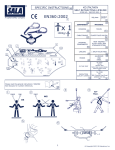
1
900 - 901
Via per Alzate, 31 - 22032 Albese con Cassano (Como) - Italy
Telefono: +39 031 429611 - Fax: +39 031 426151
E-mail: [email protected]
DISPOSITIVI DI ANCORAGGIO GOLFARI Mod. 900 M16 e 901 M16
ANCHORAGE DEVICES EYEBOLTS Mod. 900 M16 and 901 M16
DISPOSITIFS D’ANCRAGE ANNEAUX À ŒIL ROTATIF MODÈLES 900 M16 ET 901 M16
VERANKERUNGSVORRICHTUNGEN RINGÖSEN MOD. 900 M16 UND 901 M16
ISTRUZIONI PER L’INSTALLAZIONE, USO, MANUTENZIONE, ISPEZIONE PERIODICA - DISPOSITIVI DI ANCORAGGIO
RIMOVIBILI (DPI) UNI EN 795 Classe A1
Manuale di istruzioni approvate dall’Organismo Notificato n° 0426 ITALCERT srl viale Sarca, 336 20126 Milano (MI) in
occasione del rilascio dell’attestato di certificazione CE come previsto dalla D.E. 89/686/CEE.
I contenuti concordano con la norma UNI 10913:2001, la norma UNI EN 365:2005 e la norma UNI EN 795:2002
Leggere attentamente, osservare scrupolosamente il presente manuale di istruzioni. Il presente manuale deve essere
conservato
INSTRUCTIONS TO USE, MAINTAIN, AND CARRY OUT REGULAR INSPECTIONS - REMOVABLE ANCHORAGE DEVICES
(DPI)
UNI EN 795 Class A1
User Manual approved by the Notified Body n° 0426 ITALCERT srl viale Sarca, 336 20126 Milano (MI) on occasion of the
issuance of the EC certificate as required by D.E. 89/686/CEE.
The contents are in compliance with norm UNI 10913:2001, UNI EN 365:2005 and UNI EN 795:2002
Carefully read and scrupulously adhere to the present user manual. This manual must be stored and kept
DPI di 3^ Categoria (D.Lgs. 475/92; D.E. 89/686/CEE)
Impiego subordinato ad addestramento obbligatorio
DPI 3^ Category (D.Lgs. 475/92; D.E. 89/686/CEE)
Use subject to mandatory training
I dispositivi di ancoraggio oggetto del presente manuale di istruzioni sono destinati ad essere utilizzati come DPI e come tali
rientrano nel campo di applicazione della Direttiva Europea 89/686/CEE e successivi emendamenti e/o integrazioni (93/68/CEE,
93/95/CEE e 96/58/CE) relativa ai Dispositivi di Protezione Individuale (DPI). Essi sono soggetti all’obbligo della marcatura CE a
fronte della rispondenza ai requisiti essenziali di cui all’Allegato II alla Direttiva stessa.
Costituiscono, una volta installati sul posto di lavoro, un punto di collegamento sicuro per sistemi di protezione contro le cadute
dall’alto.
Le prestazioni dei dispositivi di ancoraggio sono state valutate utilizzando i requisiti previsti per la classe A1 dalla norma UNI EN
795.
The anchorage devices described in this user manual are to be used as DPI and as such fall within the scope of the European
Directive 89/686/CEE and subsequent amendments and/or integrations (93/68/CEE, 93/95/CEE and 96/58/CE) related to Personal
Protective equipment.(DPI). They are subject to the CE marking in respect of compliance with the essential requirements of Annex
II to the Directive itself.
Once installed at the workplace they are a point of secure systems against falls from above.
The performance of the anchorage devices were evaluated using the requirements for class A1 by UNI EN 795.
AVVERTENZE GENERALI
Il presente manuale fornisce istruzioni per l’utilizzo, la manutenzione, l’installazione, l’ispezione e la dismissione dei dispositivi di
ancoraggio, di seguito denominati per semplicità “golfari”.
I golfari oggetto del presente manuale si intendono Dispositivi di Protezione Individuale attribuiti personalmente all’utilizzatore,
dove ciò è applicabile;
I destinatari di questo documento sono il datore di lavoro/lavoratore, il soggetto qualificato che esegue i calcoli per verificare
l’idoneità della struttura nella quale sarà installato il dispositivo di ancoraggio, nonché colui che predispone la struttura per
accettare il dispositivo stesso.
Il datore di lavoro (utilizzatore) è responsabile della scelta, della manutenzione e dell’uso corretto dei dispositivi anticaduta
impiegati con i golfari. E’ opportuno, pertanto, che le prestazioni degli stessi e le condizioni dell’ambiente di lavoro (tirante d’aria,
possibilità di effetto pendolo, ecc.) siano valutate attentamente prima di procedere all’acquisto e all’utilizzo dei DPI necessari.
I golfari oggetto del presente manuale sono stati progettati e costruiti per assicurare la compatibilità con le tipologie di dispositivi di
protezione individuale contro le cadute dall’alto da utilizzarsi con gli stessi. E’ necessario comunque leggere attentamente,
comprendere e applicare le istruzioni per l’uso di tutti i dispositivi di protezione individuale contro le cadute dall’alto che devono
essere impiegati con i presenti sistemi di ancoraggio, anche al fine di evidenziare eventuali incompatibilità non prese in considerazione in fase di progetto.
E’ assolutamente necessario che il personale destinato ad utilizzare i dispositivi di ancoraggio e i dispositivi di protezione
individuale contro le cadute dall’alto sia informato circa i rischi da cui è protetto, sia formato e addestrato all’uso del sistema
anticaduta impiegato e ne conosca i limiti, le precauzioni da adottare e i pericoli derivanti da un utilizzo scorretto.
Qualora il prodotto venisse commercializzato al di fuori del Paese originale di destinazione, il rivenditore deve fornire le istruzioni
per l'uso, la manutenzione, l'ispezione periodica e la riparazione nella lingua del Paese in cui deve essere utilizzato il prodotto.
GARANZIA
I dispositivi di ancoraggio oggetto del presente manuale sono garantiti contro difetti di fabbricazione che possono essere ricondotti
a STAMPERIA CARCANO.
La garanzia si applica a tutti i particolari forniti NON ancora installati. STAMPERIA CARCANO non può garantire particolari che
siano già stati installati.
Per decorrenza e validità della garanzia fa fede la data indicata sulla fattura o ricevuta fiscale. Questi documenti devono essere
pertanto conservati ed esibiti in caso di richieste di applicazione delle condizioni di garanzia.
La garanzia si applica:
● a tutti i difetti di fabbricazione riconducibili al fabbricante su tutti i particolari forniti, PRIMA della loro installazione.
La garanzia non si applica:
● alla sostituzione o riparazione di elementi deformati a seguito di un arresto di una caduta;
● alla sostituzione o riparazione di elementi danneggiati e/o deformati a causa di inosservanza del presente manuale di
istruzioni;
● alla sostituzione o riparazione di elementi danneggiati e/o deformati a causa della normale usura o dell’eventuale deterioramento dovuto a condizioni ambientali eccessivamente aggressive;
● alla sostituzione o riparazione di elementi danneggiati e/o deformati se le ispezioni periodiche non sono richieste ed
effettuate almeno con la frequenza minima indicata nel presente manuale di istruzioni;
● ai dispositivi di protezione individuale impiegati con il punto di ancoraggio;
Modalità di reso in garanzia: contattare STAMPERIA CARCANO.
RESPONSABILITA’
STAMPERIA CARCANO declina ogni responsabilità per danni a persone o cose riconducibili ad un uso improprio dei golfari di
ancoraggio, intendendosi per “uso improprio” qualsiasi utilizzo non in conformità con quanto previsto nel presente manuale,
qualsiasi utilizzo non in conformità con le norme di sicurezza previste nella legislazione vigente e/o, più in generale, qualsiasi
utilizzo contro il buon senso.
STAMPERIA CARCANO inoltre declina ogni responsabilità per danni a persone o cose riconducibili a manomissioni dei golfari di
ancoraggio quali modifiche e/o riparazioni non autorizzate oppure l’impiego di eventuali parti di ricambio non fornite o non
autorizzate dal fabbricante stesso.
STAMPERIA CARCANO si riserva il diritto di modificare il progetto dei golfari di ancoraggio in funzione dell’evoluzione della
tecnica, dell’acquisizione di nuove esperienze e/o in seguito a eventuali modifiche alla legislazione vigente. Ciò non comporta
l’obbligo per il fabbricante di intervenire sui golfari fabbricati e impiegati in precedenza e sui relativi manuali di istruzioni.
1 PRESENTAZIONE DEL PRODOTTO
Nel presente manuale di istruzioni vengono descritti i dispositivi di ancoraggio trasportabili (di seguito denominati golfari) dotati di
anello girevole per il collegamento di sistemi anticaduta e di un gambo filettato per il fissaggio degli stessi dispositivi alla struttura
di posa (o struttura di sostegno).
Tali dispositivi costituiscono un punto di ancoraggio sicuro al quale collegarsi con idonei sottosistemi anticaduta costituiti da
un’imbracatura per il corpo conforme alla norma EN 361 e un assorbitore di energia con cordino integrato conforme alla norma EN
355, oppure un dispositivo anticaduta di tipo retrattile conforme alla norma EN 360, per proteggere contro le cadute dall’alto
quando si devono effettuare lavori in quota.
Il collegamento del sottosistema anticaduta è effettuato direttamente al golfare per mezzo di idonei connettori in dotazione ai
dispositivi di protezione individuale anticaduta impiegati.
In caso di caduta dell’utilizzatore l’azione frenante è ottenuta dall’intervento combinato dei dispositivi di protezione individuale
contro le cadute dall’alto e dal sostegno del golfare.
MODELLO
900 M16
901 M16
FOTO/DISEGNO
DESCRIZIONE
Dispositivo di ancoraggio per sistemi
anticaduta composto da un corpo golfare
ad anello girevole da fissare mediante vite
M16x18 ad apposito foro filettato cieco
presente su idonea struttura metallica di
posa. Consente l’attacco di due utilizzatori
Dispositivo di ancoraggio per sistemi
anticaduta composto da un corpo golfare
ad anello girevole da fissare mediante vite
M16x150 ad apposito foro filettato
passante ovvero ad apposito foro non
filettato presente su idonea struttura
metallica di posa. Consente l’attacco di
due utilizzatori
1.1 Caratteristiche
I dispositivi di ancoraggio rimovibili (DPI) oggetto del presente manuale sono stati progettati per essere installati, per il solo tempo
necessario alla esecuzione di lavori che richiedono la protezione dalle cadute dall’alto, su strutture portanti che devono avere
idonee caratteristiche.
I golfari sono progettati in modo da accettare, una volta posizionati su idonea struttura metallica (tassativamente acciaio - vedi
punto 3 “installazione”), il necessario sistema di protezione individuale contro le cadute dall’’alto e garantire che lo stesso,
correttamente applicato, non possa staccarsi involontariamente.
Data la loro versatilità e la facilità di installazione i golfari sono particolarmente adatti per essere utilizzati su grosse attrezzature o
macchinari dove, per eventuali installazioni o operazioni di manutenzione, gli operatori si trovano a lavorare ad una altezza
superiore a 2m rispetto a un piano stabile in quota (art. 107 D.Lgs. 81/2008) e devono essere equipaggiati con sistemi di
protezione dalle cadute dall’alto.
1.2 Prestazioni
Le prestazioni dei golfari sono state valutate, in condizioni di laboratorio, utilizzando i requisiti previsti per i dispositivi di Classe A1
della norma UNI EN 795.
I golfari, in combinazione con i dispositivi per la protezione contro le cadute dall’alto descritti in questo manuale, sono in grado di
sostenere un utilizzatore in caduta libera limitando la forza di arresto a 6 kN.
Per ogni modello, sono state eseguite, con esito positivo:
● prove statiche con un carico pari a 10 kN applicata per 3 minuti nella direzione in cui tale forza può essere applicata in
esercizio (UNI EN 795 paragrafo 4.3.1.1/5.2.1);
● prove dinamiche con una massa di 100 kg, collegata all’anello del golfare con un cordino senza assorbitore di energia, in
caduta libera per 2.5 m (UNI EN 795 paragrafo 4.3.1.1/5.3.2).
GENERAL WARNINGS
This manual provides instructions for use, maintenance, installation, inspection and disposal of anchorage devices hereinafter
referred to simply as “eyebolts”.
The eyebolts referred to in this manual are Individual Protection Equipment personally assigned to the user where applicable.
Recipients of this document are the employer/employee, the qualified person who performs the calculations to verify the suitability
of the structure in which the eyebolts will be installed, as well as those who set up the structure to accept the device.
The employer (user) is responsible for the selection, maintenance and correct use of the fall prevention equipment used with the
eyebolts. It is therefore advisable that the performance and the work environment conditions (air draft, possible pendulum effect etc)
are carefully assessed before purchasing and use of the necessary DPI.
The eyebolts referred to in this manual have been designed and manufactured to ensure compatibility with the types of personal
protective equipment against falls from heights to be used with them. It is still however necessary to carefully read understand and
apply the instructions to use with the present anchorage equipment and also in order to detect any incompatibility which were not
taken into consideration during the design phase.
It is absolutely necessary that the staff assigned to use anchorage devices and individual protection equipment against falls from
heights be informed and trained in relation to the fall prevention equipment used, and must also be aware of the precautions to take
and the dangers derived from incorrect use.
Should the product be marketed outside the Country’s original destination, the retailer must provide instructions for use,
maintenance and regular inspections in the language of the country where the product is to be used
GUARANTEE
The anchorage devices referred to in the present manual are guaranteed against faulty manufacturing due to STAMPERIA
CARCANO.
The guarantee applies to all STAMPERIA CARCANO components that have been supplied which have not been installed yet.
Validity of the guarantee comes into effect and is applied from the date on the invoice or receipt. These documents must be stored
in a safe place and be produced if a guarantee claim is put in
The guarantee applies to:
All manufacturing defects related to the manufacturer for all the parts supplied BEFORE installation.
The guarantee does not apply to:
● replacement or repair of deformed parts following a fall stop;
● replacement or repair of damaged and/or deformed parts due to non compliance to the user manual;
● replacement or repair of damaged parts and/or deformed due to standard wear or possible deterioration due to very bad
environmental conditions;
● replacement or repair of damaged and/or deformed parts if inspections at regular intervals are not requested and carried out
at least at the minimum frequency specified in this user manual;
● individual protection devices used with the anchorage point;
How to claim guarantee:
contact: STAMPERIA CARCANO
RESPONSIBILITY
STAMPERIA CARCANO declines responsibility for damage or damages to people or things due to improper use of eyebolts means
use that is not in conformity to the safety standards of the laws in force and/or use which cannot be deemed sensible.
STAMPERIA CARCANO in addition declines responsibility for damage or damages to people or things due to any kind of tampering
of eyebolts such as unauthorized modifications and/or repairs or the use of spare parts which have not been supplied by the
manufacturer nor authorized.
STAMPERIA CARCANO reserves the right to modify the design of based on the technical evolution, new know how gained from
experience and/or following modifications of the laws in force. The aforesaid does not oblige the manufacturer to intervene on
eyebolts which have been manufactured and used in the past nor to update the instruction manuals in any way.
1 PRESENTATION OF THE PRODUCT
The present instruction manual describes movable anchorage devices (hereinafter named eyebolts) fitted with rotating ring to
connect to anti-falling systems and a threaded shaft to fix the devices to the positioning structure (or support structure).
These devices are a safe anchorage point to which to connect to with to suitable fall-prevention subsystems made up of a body
harness in compliance to norm EN 361 and an energy absorber with integrated cord in compliance to norm EN 355, or a retractable
anti-fall device in compliance to norm EN 360, for protection against falling from heights when it is necessary to work at heights.
Connection to the fall prevention sub system is carried out directly to the eyebolt by means of suitable connectors included with the
individual anti-fall devices used.
In case of fall by the user the brake action is obtained by a combined effect of the individual protection device against falls from
height and the support of the eyebolt.
TYPE
900 M16
901 M16
PHOTO/DRAWING
DESCRIPTION
Anchorage device for anti falling systems
made up of an eyebolt with rotating ring to
fit on by means of screw M16x18 to the
specific threaded hole on the metallic
positioning structure. Enables connection
of two users
Anchorage devices for anti-fall systems
made up of a rotating ring eyebolt to fix on
by means of screw M16x150 to a specific
threaded through hole that is to a specific
un threaded hole present on the metallic
positioning
structure,
and
enables
connection of two users
1.1 Characteristics
Removable anchorage devices described in this manual have been designed to be installed strictly for the time needed to carry our
work which needs protection from falling from heights, on load bearing structures which have to have suitable characteristics.
Eyebolts have been designed to accept once they have been positioned on a suitable metallic structure (strictly steel – see point 3
“installation”), the necessary individual protection system against falls and ensure that they are properly applied and cannot come
off accidentally.
Due to the versatility and easy installation the eyebolts are very suitable to be used on large equipment or machinery where it is
necessary to install or carry out maintenance operations, operators have to work at a height over 2m with respect to a stable surface
at heights (art. 107 D.Lgs. 81/2008) and must use protection systems to prevent falls from a height.
1.2 Performance
The performance of eyebolts have been assessed in lab conditions, using the requisites foreseen for Class A1 devices for norm UNI
EN 795.
Eyebolts together with devices to protect from falling from heights described in this manual are capable of supporting a user in free
fall by limiting the impact force to 6 kN.
For each model the following tests with positive results have been carried out:
● Static tests with a load of 10KN applied for 3 minutes in the direction in which this force can be applied in service (UNI EN 795
paragraph 4.3.1.1/5.2.1);
● Dynamic tests with a mass of 100 kg, connected to the eyebolt ring with a cord without Energy absorber in free fall for 2.5 m
(UNI EN 795 paragraph 4.3.1.1/5.3.2).
INSTRUCTIONS D’INSTALLATION, D’UTILISATION, D’ENTRETIEN ET D’INSPECTION PÉRIODIQUE - DISPOSITIFS
D’ANCRAGE AMOVIBLES (DPI) UNI EN 795 Classe A1
ANLEITUNG ZU INSTALLATION, GEBRAUCH, WARTUNG REGELMÄSSIGER KONTROLLE - ABNEHMBARE VERANKERUNGSVORRICHTUNGEN (PSM) UNI EN 795 Klasse A1
Manuel d’instructions approuvé par l’organisme notifié n° 0426 ITALCERT srl, viale Sarca, 336 - 20126 Milan (MI) à
l’occasion de la délivrance de l’attestation de certification CE, comme prévu par la D.E. 89/686/CEE.
Les contenus respectent les normes UNI 10913:2001, UNI EN 365:2005 et UNI EN 795:2002.
Gebrauchsanweisung genehmigt von der Notifizierten Einrichtung Nr. 0426 ITALCERT srl, Viale Sarca, 336 20126 Mailand
(MI), anlässlich der Ausstellung der CE-Zertifizierungsbescheinigung, gemäß Vorgabe des D.E. 89/686/EWG auf.
Die Inhalte entsprechen der Norm UNI 10913:2001, der Norm UNI EN 365:2005 sowie der Norm UNI EN 795:2002
Lire attentivement et observer scrupuleusement le présent manuel d’instructions. Le présent manuel doit être conservé.
Lesen Sie diese Gebrauchsanweisung sorgfältig und beachten Sie sie genau. Dieses Handbuch muss aufbewahrt werden.
DPI de 3e catégorie (Décret législatif 475/92 et Décret européen 89/686/CEE)
Utilisation subordonnée à une formation obligatoire
PSM der 3. Kategorie (Gesetzesverordnung 475/92; D.E. 89/686/EWG)
Der Einsatz unterliegt einer obligatorischen Schulung.
Les dispositifs d’ancrage objet du présent manuel d’instructions sont destinés à être utilisés comme DPI et rentrent, comme tels,
dans le champ d’application de la directive européenne 89/686/CEE et de ses intégrations et/ou amendements successifs
(93/68/CEE, 93/95/CEE et 96/58/CE), relative aux dispositifs de protection individuelle (DPI). Ils sont soumis à l’obligation de
marquage CE indiquant l’observation des conditions requises essentielle de l’annexe II de cette directive.
Ils constituent, après leur installation sur le poste de travail, un point de raccordement sécurisé pour les systèmes de protection
contre les chutes de hauteur (par le haut).
Les performances des dispositifs d’ancrage ont été évaluées selon les conditions requises par la classe A1 de la norme UNI EN
795.
Die Verankerungsvorrichtungen, die den Gegenstand dieser Gebrauchsanweisung bilden, sind dazu bestimmt, als PSM benutzt zu
werden und fallen als solche in den Anwendungsbereich der Europäischen Richtlinie 89/686/EWG und nachfolgenden Überarbeitungen und / oder Ergänzungen (93/68/EWG, 93/95/EWG und 96/58/CE) bezüglich der Persönlichen Schutzmittel (PSM). Sie
unterliegen der Pflicht zur CE-Kennzeichnung hinsichtlich ihrer Übereinstimmung mit den grundlegenden Anforderungen gemäß
Anlage II dieser Richtlinie.
Nach ihrer Installation am Arbeitsplatz verkörpern sie eine sichere Anschlussstelle für Systeme zum Schutz vor einem Absturz.
Die Leistungen der Verankerungsvorrichtungen wurden unter Verwendung der für die Klasse A1 von der Norm UNI EN 795
vorgesehenen Anforderungen bewertet.
AVERTISSEMENTS GÉNÉRAUX
Le présent manuel fournit des instructions pour l’utilisation, l’entretien, l’installation, l’inspection et la mise au rebut des dispositifs
d’ancrage, dénommés plus simplement « anneaux » par la suite.
Les anneaux objet du présent manuel sont des dispositifs de protection individuelle attribués personnellement à l’utilisateur, là où
ils sont applicables.
Les destinataires de ce document sont l’employeur / travailleur, le sujet qualifié exécutant les calculs de vérification de la structure
sur laquelle sera installé le dispositif d’ancrage, ainsi que le sujet préparant la structure pour recevoir ce dispositif.
L’employeur (utilisateur) est responsable du choix, de l’entretien et de la bonne utilisation des dispositifs antichute utilisés avec les
anneaux. Il s’avère donc nécessaire que les performances de ces dispositifs et les conditions de l’environnement de travail (tirant
d’air, possibilité d’effet balancier, etc.) soient évaluées attentivement avant de procéder à l’achat à l’utilisation des DPI nécessaires.
Les anneaux objet du présent manuel ont été conçus et fabriqués pour garantir leur compatibilité avec les types de dispositifs de
protection individuelle contre les chutes de hauteur à employer. Il s’avère nécessaire de lire attentivement, de comprendre et
d’appliquer les instructions d’utilisation de tous les dispositifs de protection individuelle contre les chutes de hauteur, qui doivent
être utilisés avec les présents systèmes d’ancrage, afin de mettre également en évidence les éventuelles incompatibilités non
prises en compte lors de la conception.
Il s’avère indispensable que le personnel destiné à utiliser les dispositifs d’ancrage et les dispositifs de protection individuelle
contre les chutes de hauteur soit informé sur les risques pour lesquels il est protégé, qu’il soit formé et informé de l’utilisation du
système antichute utilisé et qu’il en connaisse les limites, les précautions à prendre et les dangers dérivant d’un usage incorrect.
Si le produit est commercialisé en dehors du pays de destination d’origine, le revendeur devra fournir les instructions d’utilisation,
d’entretien, d'inspection périodique et de réparation dans la langue du pays où sera utilisé le produit.
ALLGEMEINE HINWEISE
Diese Gebrauchsanweisung liefert Hinweise zu Verwendung, Wartung, Installation, Prüfung und Außerbetriebnahme der Verankerungsvorrichtungen, die im Weiteren aus Gründen der Vereinfachung als “Ringösen” bezeichnet werden.
Die Ringösen, die den Gegenstand dieses Handbuches bilden, sind Persönliche Schutzmittel, die wo dies anwendbar ist,
persönlich dem Anwender zugeteilt werden;
Die Zielgruppe dieses Dokuments sind der Arbeitgeber/Beschäftigte, der Fachmann, der die Berechnungen zur Prüfung der
Eignung der Konstruktion ausführt, an der die Verankerungsvorrichtung installiert wird, sowie diejenigen, die die Konstruktion zur
Aufnahme dieser Vorrichtung vorrüsten.
Der Arbeitgeber (Anwender) ist für die Auswahl, die Wartung und den richtigen Gebrauch der mit den Ringösen verwendeten
Absturzschutzmittel verantwortlich. Des ist deshalb notwendig, dass deren Leistungen und die Bedingungen der Arbeitsumgebung
(Luftzug, Möglichkeit einer Pendelwirkung, usw.) sorgfältig bewertet werden, bevor die notwendigen PSM erworben und eingesetzt
werden.
Die Ringösen, die den Gegenstand dieses Handbuches bilden, wurden entworfen und gebaut, um die Kompatibilität zu den
verschiedenen persönlichen Absturzschutzmitteln zu garantieren, die mit diesen verwendet werden. In jedem Fall ist es notwendig,
die Gebrauchsanweisungen aller persönlichen Absturzschutzmittel sorgfältig zu lesen, zu verstehen und anzuwenden, die mit
diesen Verankerungssystemen eingesetyt werden. Dies hat auch den Zweck, eventuelle Nichtübereinstimmungen zu ermitteln, die
beim Entwurf nicht berücksichtigt wurden.
Es ist unbedingt notwendig, dass das zur Benutzung der Verankerungsvorrichtungen und der persönlichen Absturzschutzmittel
bestimmte Personal hinsichtlich der Gefahren informiert ist, vor denen es geschützt wird. Es muss geschult und in den Gebrauch
des verwendeten Absturzschutzes eingewiesen werden, seine Grenzen, die anzuwendenden Vorsichtsmaßnahmen und die sich
aus einem falschen Gebrauch ergebenden Gefahren kennen.
Sollte das Produkt außerhalb des ursprünglichen Bestimmungslandes eingesetzt werden, muss der Händler die Anleitungen zu
Gebrauch, Wartung, regelmäßige Kontrolle und Reparatur in der Sprache des Landes bereitstellen, in dem das Produkt zum
Einsatz kommt.
GARANTIE
Les dispositifs d’ancrage objet du présent manuel sont garantis contre les défauts de fabrication pouvant être reconduits à
STAMPERIA CARCANO.
La garantie s’applique sur toutes les pièces fournies NON encore installées. STAMPERIA CARCANO ne peut garantir des pièces
ayant déjà été installées.
Pour la date de début de garantie et sa validité, fait foi la date indiquée sur la facture ou le reçu fiscal. Ces documents doivent donc
être conservés et exhibés en cas de demande d’application des conditions de garantie.
La garantie s’applique:
● à tous les défauts de fabrication en lien direct avec le constructeur sur toutes les pièces fournies, AVANT leur installation.
La garantie ne s’applique pas :
● au remplacement ou à la réparation d’éléments déformés à la suite d’un arrêt de chute,
● au remplacement ou à la réparation d’éléments détériorés et/ou déformés à cause de l’inobservation du présent manuel
d’instructions,
● au remplacement ou à la réparation d’éléments détériorés et/ou déformés à cause de l’usure courante ou d’une détérioration
due à des conditions ambiantes excessivement agressives,
● au remplacement ou à la réparation d’éléments détériorés et/ou déformés si les inspections périodiques n’ont pas été
demandées ni effectuées au moins avec la fréquence minimale indiquée dans le présent manuel d’instructions,
● aux dispositifs de protection individuelle utilisés avec le point d’ancrage.
Modalités de retour en garantie: contacter STAMPERIA CARCANO.
RESPONSABILITÉ
STAMPERIA CARCANO décline toute responsabilité pour les dommages aux biens et aux personnes dus à un usage impropre
des anneaux d’ancrage. On entend, par « usage impropre », toute utilisation non conforme aux indications du présent manuel,
toute utilisation non conforme aux normes de sécurité prévues par la législation en vigueur et/ou, plus généralement, toute
utilisation en dépit du bon sens.
STAMPERIA CARCANO décline également toute responsabilité pour les dommages aux personnes ou aux biens dérivant
d’altérations des anneaux d’ancrage, comme les modifications et/ou les réparations non autorisées ou bien de l’emploi de pièces
de rechange non fournies ou non autorisées par le constructeur.
STAMPERIA CARCANO se réserve le droit de modifier le projet des anneaux d’ancrage en fonction de l’évolution de la technique,
de l’acquisition de nouvelles expériences et/ou à la suite d’éventuelles modification de la législation en vigueur, sans que cela
n’entraîne l’obligation, pour le constructeur, d’intervenir sur les anneaux précédemment fabriqués et utilisés, ni sur les manuels
d’instructions correspondants.
1 PRÉSENTATION DU PRODUIT
Le présent manuel d’instructions décrit les dispositifs d’ancrage transportables (par la suite dénommés anneaux) équipés d’un œil
rotatif pour le raccordement de systèmes antichute et d’une tige filetée pour leur fixation à la structure de pose (ou structure de
soutien).
Ces dispositifs constituent un point d’ancrage sécurisé auquel se raccorder à l’aide de sous-systèmes antichute composés d’un
harnais conforme à la norme EN 361 et d’un absorbeur d’énergie à longe intégrée conforme à la norme EN 355, ou bien d’un
dispositif antichute de type rétractable conforme à la norme EN 360, en protection des chutes lorsque l’on doit exécuter des travaux
en hauteur.
Le raccordement du sous-système antichute s’effectue directement sur l’anneau à l’aide des connecteurs fournis avec les
dispositifs utilisés de protection individuelle antichute.
En cas de chute de l’utilisateur, l’action de freinage est réalisée par l’intervention combinée des dispositifs de protection
individuelle antichute et du soutien de l’anneau.
MODÈLE
900 M16
901 M16
PHOTO / PLAN
DESCRIPTION
Dispositif d’ancrage pour systèmes
antichute, composé d’un anneau à œil
rotatif à fixer à l’aide d’une vis M 16x18
dans un trou borgne fileté d’une structure
métallique de pose. Permet le raccordement de deux utilisateurs.
Dispositif d’ancrage pour systèmes
antichute, composé d’un anneau à œil
rotatif à fixer à l’aide d’une vis M 16x150
dans un trou fileté passant ou dans un
trou non fileté de la structure métallique
de pose. Permet le raccordement de deux
utilisateurs.
GARANTIE
Für die Verankerungsvorrichtungen, die den Gegenstand dieses Handbuches bilden, wird eine Garantie hinsichtlich
Herstellungsmängeln gewährt, die auf die Firma STAMPERIA CARCANO zurückführbar sind.
Die Garantie kommt für alle gelieferten Einzelteile zur Anwendung, die noch NICHT installiert wurden. Die Firma STAMPERIA
CARCANO kann nicht für Einzelteile garantieren, die bereits installiert wurden.
Hinsichtlich Beginn und Gültigkeit der Garantie gilt das auf der Rechnung oder dem Kassenzettel angegebene Datum. Diese
Dokumente müssen deshalb aufbewahrt und bei Forderung einer Anwendung der Garantiebedingungen vorgelegt werden.
Die Garantie kommt zur Anwendung:
● auf alle Herstellungsmängel an allen gelieferten Bauteilen, die auf den Hersteller zurückführbar sind, VOR deren Installation.
Die Garantie kommt nicht zur Anwendung:
● auf den Ersatz oder die Reparatur von in Folge eines gehemmten Absturzes verformten Elementen;
● auf den Ersatz oder die Reparatur von in Folge der Nichtbeachtung dieser Gebrauchsanweisung beschädigten und / oder
verformten Elementen;
● auf den Ersatz oder die Reparatur von in Folge der normalen Abnutzung oder des eventuellen Verschleißes auf Grund
besonders aggressiver Witterungsbedingungen beschädigten und / oder verformten Elementen;
● auf den Ersatz oder die Reparatur von beschädigten und / oder verformten Elementen, wenn die regelmäßigen Kontrollen
nicht gefordert und zumindest mit der in dieser Gebrauchsanweisung angegebenen Mindestfrist ausgeführt wurden;
● auf die persönlichen Schutzmittel, die mit der Verankerungsstelle verwendet werden
Rückgabe im Garantiezeitraum: Setzen Sie sich bitte mit der Firma STAMPERIA CARCANO in Verbindung.
HAFTUNG
STAMPERIA CARCANO declines responsibility for damage or damages to people or things due to improper use of eyebolts means
use that is not in Die Firma STAMPERIA CARCANO lehnt jegliche Haftung für Personen- oder Sachschäden ab, die auf einen
unsachgemäßen Gebrauch der zur Verankerung dienenden Ringösen zurückzuführen sind. Dabei wird unter “unsachgemäßem
Gebrauch” jeglicher Einsatz verstanden, der von dem in diesem Handbuch vorgesehenen, von den in der geltenden Gesetzgebung
vorgesehenen Sicherheitsbestimmungen abweicht und / oder jeglicher Einsatz entgegen der Vernunft.
Die Firma STAMPERIA CARCANO lehnt außerdem jegliche Haftung für Personen- oder Sachschäden ab, die auf Veränderungen
den zur Verankerung dienenden Ringösen vorgenommen werden, wie ungenehmigte Änderungen und / oder Reparaturen oder der
Einsatz eventueller Ersatzteile, die nicht vom Hersteller geliefert oder zugelassen wurden.
Die Firma STAMPERIA CARCANO behält sich vor, den Entwurf der zur Verankerung dienenden Ringösen in Abhängigkeit von der
Weiterentwicklung der Technik, der Erlangung neuer Erfahrungen und / oder in Folge eventueller Änderungen an der geltenden
Gesetzgebung zu verändern. Dies zieht für den Hersteller nicht die Pflicht nach sich, auch die zuvor hergestellten und eingesetzten
Ringösen bzw. die entsprechenden Gebrauchsanweisungen zu verändern.
1 BESCHREIBUNG DES PRODUKTES
In dieser Gebrauchsanweisung werden die abnehmbaren Verankerungsvorrichtungen (im Weiteren als Ringösen bezeichnet)
beschrieben, die mit einem drehbaren Ring zur Verbindung mit Absturzschutzsystemen und einem Gewindestab zur Befestigung
der Vorrichtungen an der Einbaukonstruktion (oder Stützkonstruktion) ausgestattet sind.
Diese Vorrichtungen bilden eine sichere Verankerungsstelle, an der eine Verbindung mit geeigneten Untersystemen zum
Absturzschutz bestehend aus einem Gurt für den Körper entsprechend der Norm EN 361 und einem Energieabsorber mit
integriertem Seil entsprechend der Norm EN 355, oder ein Absturzschutz einziehbarer Art entsprechend der Norm EN 360,
angeschlossen werden können, um vor einem Absturz zu schützen, wenn Arbeiten in der Höhe ausgeführt werden müssen.
Der Anschluss des als Absturzschutz dienenden Untersystems erfolgt mittels geeigneter Verbinder, die mit den eingesetzten
persönlichen Absturzschutzmitteln geliefert werden, direkt an der Ringöse.
Bei einem Absturz des Anwenders wird die Bremswirkung durch die kombinierte Wirkung der persönlichen Absturzschutzmittel und
der Halterung der Ringöse erzielt.
MODELL
900 M16
901 M16
FOTO/ZEICHNUNG
BESCHREIBUNG
Verankerungsvorrichtung
für
Absturzschutzsysteme, bestehend aus
einer Ringöse mit drehbarem Ring, der
mittels Schraube M16x18 in einer dazu
dienenden Gewindeblindbohrung an einer
geeigneten Einbaukonstruktion aus Metall
befestigt wird. Ermöglicht die Verankerung von zwei Anwendern
Verankerungsvorrichtung
für
Absturzschutzsysteme, bestehend aus
einer Ringöse mit drehbarem Ring, der
mittels Schraube M16x150 in einer dazu
dienenden Gewindedurchgangsbohrung
bzw. an einer Bohrung ohne Gewinde an
einer geeigneten Einbaukonstruktion aus
Metall befestigt wird. Ermöglicht die
Verankerung von zwei Anwendern
1.1 Caractéristiques
Les dispositifs d’ancrage amovibles (DPI), objet du présent manuel, ont été étudiés pour être installés sur la seule durée
nécessaire à l’exécution des travaux exigeant la protection contre les chutes de hauteur, sur des structures portantes devant
présenter des caractéristiques appropriées.
Les anneaux ont été étudiés de manière à accepter, après leur positionnement sur une structure métallique appropriée
(uniquement en acier - voir le point 3 « Installation »), le système nécessaire de protection individuelle antichute et garantir que
celui-ci ne puisse pas, s’il est correctement appliqué, se décrocher involontairement.
Vu leur souplesse d’utilisation et leur facilité d’installation, les anneaux sont particulièrement adaptés pour une utilisation sur de
gros outillages et des machines où, pour l’installation ou l’entretien, les opérateurs doivent travailler à des hauteurs supérieures à
2 m par rapport à un plan en hauteur (art. 107 du décret législatif 81/2008) et doivent être équipés de systèmes de protection contre
les chutes de hauteur.
1.1 Eigenschaften
Die abnehmbaren Verankerungsvorrichtungen (PSM), die den Gegenstand dieses Handbuches bilden, wurden entworfen, um nur
für die zum Ausführen der Arbeiten, die einen Absturzschutz erfordern, erforderliche Zeit an tragenden Konstruktionen installiert zu
werden, die geeignete Eigenschaften besitzen müssen.
Die Ringösen wurden so entworfen, dass sie nach ihrem Anbringen an einer geeigneten Metallkonstruktion (unbedingt aus Stahl siehe Punkt 3 "Installation") das notwendige persönliche Absturzschutzsystem aufnehmen und garantieren, dass sich dieses bei
richtiger Anwendung nicht plötzlich lösen kann.
Auf Grund ihrer Vielseitigkeit und mühelosen Installierbarkeit sind die Ringösen besonders für eine Verwendung an großen
Ausrüstungen oder Maschinen geeignet, wo die Beschäftigten bei eventuellen Installationen oder Wartungsarbeiten in einer Höhe
von mehr als 2 m zu einer stabilen Ebene arbeiten (Art. 107 Gesetzesverordnung 81/2008) und mit Absturzschutzsystemen
ausgestattet sein müssen.
1.2 Performances
es performances des anneaux ont été évaluées, dans les conditions de laboratoire, selon les conditions requises par la norme UNI
EN 795 pour les dispositifs de Classe A1.
Les anneaux, en association avec les dispositifs de protection contre les chutes de hauteur décrits dans ce manuel, sont en
mesure de soutenir un utilisateur en chute libre en limitant la force d’arrêt à 6 kN.
Pour chaque modèle, les essais suivant ont été exécutés et ont donné un résultat positif:
● essais statiques avec une charge de 10 kN appliquée pendant 3 minutes dans la direction dans laquelle cette force peut être
appliquée en service (UNI EN 795, paragraphe 4.3.1.1/5.2.1),
● essais dynamiques avec une masse de 100 kg raccordée à l’anneau avec une longe sans absorbeur d’énergie, en chute
libre de 2,5 m (UNI EN 795, paragraphe 4.3.1.1/5.3.2).
1.2 Leistungen
Die Leistungen der Ringösen wurden bei Laborbedingungen unter Verwendung der für Vorrichtungen der Klasse A1 der Norm UNI
EN 795 vorgesehenen Anforderungen bewertet.
Die Ringösen sind zusammen mit den in diesem Handbuch beschriebenen Absturzschutzvorrichtungen in der Lage, einen
Anwender in freiem Fall bei Begrenzung der Bremskraft auf 6 kN aufzufangen.
Bei jedem Modell wurden mit positivem Ergebnis ausgeführt:
● statische Tests mit einer Last von 10 kN, die über 3 min in der Richtung angelegt wurde, in der diese Kraft beim Einsatz
angewandt werden kann (UNI EN 795 Abschnitt 4.3.1.1/5.2.1);
● dynamische Tests mit einer Masse von 100 kg, verbunden mit dem Ring der Ringöse über ein Seil ohne Energieabsorber, in
freiem Fall über 2,5 m (UNI EN 795 Abschnitt 4.3.1.1/5.3.2).
1.3 Marcatura
Ogni golfare riporta la marcatura identificativa del modello, la marcatura prevista dalle norme tecniche di riferimento UNI EN 795
e UNI EN 365 e la marcatura di conformità alla D.E. 89/686/CEE.
Gli elementi che compongono la marcatura dei golfari sono esemplificati di seguito:
1.3 Markings
Each eyebolt has identification marking of the type, in compliance to the technical norms UNI EN 795 and UNI EN 365 and the
compliance marking D.E. 89/686/CEE.
The elements which make up eyebolt marking as follows:
1.3 Marquage
Chaque anneau reporte le marquage d’identification du modèle, le marquage prévu par les normes techniques de référence UNI
EN 795 et UNI EN 365 et le marquage de conformité à la D.E. 89/686/CEE.
Les éléments du marquage des anneaux sont illustrés ci-dessous:
1.3 Kennzeichnung
Jede Ringöse weist die Kennzeichnung des Modells, die von den technischen Bezugsbestimmungen UNI EN 795 und UNI EN 365
vorgesehene Markierung sowie die Kennzeichnung der Konformität zur D.E. 89/686/EWG auf.
Die zur Kennzeichnung der Ringösen gehörigen Elemente werden nachfolgend beispielhaft beschrieben:
Per esigenze di produzione la disposizione degli elementi illustrati in marcatura potrà non corrispondere all’esempio riportato
sopra.
For production needs the positioning of the elements illustrated in marking may not correspond to the example above.
Pour des exigences de production, la disposition des éléments illustrés sur le marquage pourrait ne pas correspondre à l’exemple
ci-dessus.
Aus Erfordernissen der Produktion entspricht die Anordnung der zur Kennzeichnung erläuterten Elemente unter Umständen nicht
dem oben aufgeführten Beispiel.
2 INSTRUCTIONS D’UTILISATION
2 GEBRAUCHSANWEISUNG
2.1 Dispositions générales
Les anneaux objet du présent manuel d’instructions sont des dispositifs de protection individuelle et, comme tels, ils doivent être
fournis à l’utilisateur.
Ils doivent être impérativement mis en œuvre par celui-ci lors de l’utilisation et retirés en fin des travaux en ayant exigé l’installation.
Ces dispositifs doivent être correctement montés sur leurs sièges facilement identifiables, que l’utilisateur doit trouver déjà
préparés sur les structures (voir le point 3 « Installation »).
Les anneaux d’ancrage doivent uniquement être utilisés pour la protection contre les chutes de hauteur ou bien employés pour la
retenue s’ils sont utilisés avec des dispositifs spécifiques appropriés. Toute utilisation des anneaux en dehors de ce qui indiqué
dans le présent manuel peut entraîner une exposition à des risques non prévus pouvant, à leur tour, entraîner des blessures
graves à caractère permanent, voire la mort.
Il s’avère primordial que le personnel utilisant les anneaux d’ancrage et les dispositifs de protection individuelle contre les chutes
de hauteur soit informé sur les risques contre lesquels il est protégé, soit formé à l’emploi des systèmes antichute et en connaisse
les limites, les précautions à prendre et les dangers dérivant d’un mauvais usage.
Il s’avère également primordial que ce personnel soit en bonne condition physique et en bonne santé de manière à opérer en toute
sécurité lors de ses activités courantes et en cas d’urgence. Lors de l’usage, l’utilisateur ne doit pas être sous l’emprise de
médicaments, d’alcool ou de substances qui pourraient compromettre son équilibre, son attention et ses réflexes.
Les anneaux d’ancrage ne doivent pas être employés au-delà des limitations d’utilisation ou bien pour des usages différents de
ceux de la destination d’utilisation prévue (voir le point 2.8 « Limitations et précautions d’utilisation »).
Est reportée, ci-dessous, une liste non exhaustive et purement indicative des risques non éliminables, liés à l’utilisation des
anneaux d’ancrage et des dispositifs de protection individuelle contre les chutes de hauteur:
● risque prédominant de chute à la suite d’une chute de hauteur,
● risque subséquent à la chute dérivant de l’oscillation du corps avec choc contre des obstacles (effet balancier) ; de l’arrêt du
mouvement de chute par l’effet des contraintes transmises par le harnais au corps ; de la suspension inerte du corps de
l’utilisateur qui reste accroché au dispositif d’arrêt de la chute et de la durée de permanence dans cette position,
● risque connexe aux dispositifs de protection individuelle dérivant d’une mauvaise adaptabilité des dispositifs à l’utilisateur,
d’une entrave à la liberté de mouvements provoquée par les dispositifs,
● risque provoquant la chute qui dérive d’une adhérence insuffisante des chaussures, de vertiges, d’un éblouissement, d’une
faible visibilité, de coups de chaleur ou de soleil, d’une chute rapide de la température,
● risque spécifique de l’activité pouvant être de nature mécanique (bords anguleux, outils coupants, chute d’objets, etc.), de
nature thermique (étincelles, flammes libres, etc.), de nature chimique ou électrique,
● risque de nature atmosphérique dérivant du vent, de la pluie ou de la glace sur les surfaces de piétinement, etc.
2.1 Allgemeine Bestimmungen
Die Ringösen, die den Gegenstand dieses Handbuches bilden, sind persönliche Schutzmittel und werden dem Anwender als
solche zur Verfügung gestellt.
Sie müssen von diesem unbedingt bei ihrer Verwendung montiert und am Ende der Arbeit, zu deren Installation erforderlich war,
wieder entfernt werden.
Diese Vorrichtungen müssen angemessen in den entsprechenden Aufnahmen montiert werden, die mühelos für den Anwender
auffindbar und bereits an geeigneten Konstruktionen vorgerüstet sein müssen (siehe Punkt 3 “Installation”)
Die zur Verankerung dienenden Ringösen dürfen allein als Absturzschutz oder zum Abfangen eingesetzt werden, wenn sie mit
spezifischen und geeigneten Vorrichtungen verwendet werden. Jeglicher Einsatz der Ringösen, außerhalb der Vorgaben in diesem
Handbuch, kann zu einer Belastung durch unvorhergesehene Gefahren führen, die wiederum schwere und permanente Verletzungen sowie, in den schwersten Fällen, den Tod zur Folge haben können.
Es ist unbedingt notwendig, dass das Personal, das die zur Verankerung dienenden Ringösen und die persönlichen
Absturzschutzmittel benutzt, hinsichtlich der Gefahren informiert ist, vor denen es geschützt wird. Es muss geschult und in den
Gebrauch des Absturzschutzsystems eingewiesen werden, seine Grenzen, die anzuwendenden Vorsichtsmaßnahmen und die
sich aus einem falschen Gebrauch ergebenden Gefahren kennen.
Außerdem ist es unbedingt notwendig, dass sich dieses Personal in gutem körperlichen und gesundheitlichem Zustand befindet,
so dass es während der normalen Tätigkeit sowie in Notfällen unter sicheren Bedingungen arbeiten kann. Während des Gebrauchs
darf der Anwender nicht unter Einfluss von Arzneimitteln, Alkohol oder Drogen stehen, die das Gleichgewicht, die Aufmerksamkeit
und die Reflexe beeinträchtigen können.
Die zur Verankerung dienenden Ringösen dürfen nicht außerhalb der Einsatzgrenzen oder für andere Zwecke eingesetzt werden,
als dem vorgesehenen Verwendungszweck (siehe Punkt 2.8 “Beschränkungen und Vorsichtsmaßnahmen beim Gebrauch”).
Es folgt eine nicht umfassende und rein zu Informationszwecken dienende Liste der nicht beseitigbaren Gefahren im Zusammenhang mit dem Gebrauch der zur Verankerung dienenden Ringösen und der persönlichen Absturzschutzmittel:
● Gefahr durch Sturz in Folge eines Absturzes;
● Gefahr in Folge des Sturzes durch das Schwingen des Körpers mit Stoß gegen Hindernisse (Pendeleffekt); durch das
Stoppen der Fallbewegung durch die vom Gurt auf den Körper ausgeübten Belastungen; durch das inerte Schweben des
Körpers, der am Absturzschutz hängen bleibt und durch die Dauer des Verbleibs in dieser Position;
● Gefahr in Verbindung mit den persönlichen Schutzmitteln aus einer nicht vollständigen Anpassungsfähigkeit der Vorrichtungen an den Anwender; durch die Einschränkung der Bewegungsfreiheit durch diese Vorrichtungen;
● Gefahr, die den Absturz durch eine unzureichende Haftung des Schuhwerks bewirkt; durch Schwindelgefühl; durch
Blendung der Augen; durch geringe Sicht; durch Hitzeschläge oder Sonne; durch eine schnelle Verringerung der Temperatur;
● spezifsche Gefahren der Arbeitstätigkeit, die mechanischer Art (scharfe Kanten, scharfe Werkzeuge, Herabfallen von
Gegenständen, usw.), thermischer Art (Funken, offene Flammen, usw.), chemischer oder elektrischer Art sein kann;
● Gefahr atmosphärischer Art durch Wind, Regen oder Eis auf den Trittflächen, usw.
2 ISTRUZIONI PER L’USO
2.1 Disposizioni generali
I golfari oggetto del presente manuale di istruzioni sono dispositivi di protezione individuale e, come tali, sono in dotazione
all’utilizzatore.
Devono essere tassativamente posti in opera dallo stesso al momento del loro utilizzo e tolti al termine del lavoro che ne ha
richiesto l’installazione.
Detti dispositivi devono essere adeguatamente montati nelle apposite sedi facilmente identificabili che l’utilizzatore deve trovare
già predisposte su strutture adeguate (vedi punto 3 “installazione”)
I golfari di ancoraggio devono essere utilizzati unicamente per la protezione contro le cadute dall’alto oppure impiegati per la
trattenuta se utilizzati con specifici e idonei dispositivi. Qualsiasi impiego dei golfari al di fuori di quanto previsto nel presente
manuale può comportare l’esposizione a rischi non previsti che possono comportare a loro volta lesioni gravi e a carattere
permanente nonché, nei casi più gravi, la morte.
E’ strettamente necessario che il personale che utilizza i golfari di ancoraggio e i dispositivi di protezione individuale contro le
cadute dall’alto sia informato circa i rischi da cui è protetto, sia formato e addestrato all’uso dei sistemi anticaduta e ne conosca i
limiti, le precauzioni da adottare e i pericoli derivanti da un utilizzo scorretto.
E’ inoltre strettamente necessario che lo stesso personale sia in buone condizioni fisiche e di salute in modo da operare in
sicurezza durante la normale attività e in emergenza. Durante l’uso, l’utilizzatore non deve essere sotto l’effetto di medicinali, alcool
o droghe che possano comprometterne l’equilibrio, l’attenzione e i riflessi.
I golfari di ancoraggio non devono essere utilizzati oltre le limitazioni d’uso oppure per altri impieghi diversi dalla destinazione d’uso
(vedi punto 2.8 “Limitazioni e precauzioni d’uso”).
Di seguito si riporta un elenco non esaustivo e puramente informativo dei rischi non eliminabili legati all’uso dei golfari di
ancoraggio e dei dispositivi di protezione individuale contro le cadute dall’alto:
● rischio prevalente di caduta a seguito di caduta dall’alto;
● rischio susseguente alla caduta derivante dall’oscillazione del corpo con urto contro ostacoli (effetto pendolo); dall’arresto
del moto di caduta per effetto delle sollecitazioni trasmesse dall’imbracatura sul corpo; dalla sospensione inerte del corpo
dell’utilizzatore che resta appeso al dispositivo di arresto caduta e dal tempo di permanenza in tale posizione;
● rischio connesso ai dispositivi di protezione individuale derivante da una non perfetta adattabilità dei dispositivi
all’utilizzatore; dall’intralcio alla libertà dei movimenti causata dai dispositivi stessi;
● rischio innescante la caduta derivante da una insufficiente aderenza delle calzature; da vertigini; da abbagliamento degli
occhi; da scarsa visibilità; da colpi di calore o di sole; da un rapido abbassamento della temperatura;
● rischio specifico dell’attività lavorativa che può essere di natura meccanica (bordi spigolosi, attrezzi taglienti, caduta di
oggetti, ecc.); di natura termica (scintille, fiamme libere, ecc.); di natura chimica o elettrica
● rischio di natura atmosferica derivante da vento, pioggia o ghiaccio sulle superfici di calpestio, ecc.
2.2 Dispositivi di protezione individuale
I golfari di ancoraggio possono essere utilizzati esclusivamente in abbinamento con sistemi per la protezione contro le cadute
dall’alto.
Deve essere considerato il fatto che anche gli altri dispositivi di protezione individuale impiegati ricadono nel campo di applicazione
della Dir. 89/686/CEE e devono obbligatoriamente essere marcati CE e possedere tutta la documentazione necessaria a corredo.
E’ severamente vietato l’uso di dispositivi di protezione individuale contro le cadute dall’alto non conformi ai requisiti essenziali di
salute e sicurezza di cui all’Allegato II della Direttiva 89/686/CEE.
Deve essere considerato il fatto che una imbracatura per il corpo è l’unico dispositivo di presa del corpo adatto per essere utilizzato
in un sistema di arresto caduta.
Una volta determinato il tirante d’aria libero al di sotto del piano di calpestio, deve essere selezionato un adeguato dispositivo
anticaduta in modo da rendere minima la distanza di arresto caduta.
Un’imbracatura con dispositivo anticaduta di tipo retrattile offrirà all’utilizzatore una maggiore mobilità esponendolo al tempo stesso
ad un effetto pendolo più elevato, che potrebbe rendere necessaria l’installazione di ancoraggi di deviazione caduta.
Un’imbracatura con cordino anticaduta con assorbitore di energia integrato (la cui lunghezza massima è 2 m) offrirà una mobilità
inferiore dell’utilizzatore riducendo, però, l’effetto pendolo in caso di caduta.
Si richiama l’attenzione circa il fatto che sul mercato sono presenti diversi dispositivi di collegamento (assorbitori di energia, cordini,
ecc.) di diverse lunghezze, caratteristiche e prestazioni. E’ strettamente necessario che la scelta dei dispositivi di protezione
individuale da utilizzare sia attentamente valutata in funzione di tutti i fattori prevedibili che possono influire sulla stessa. Per
esempio si dovrà tenere conto della posizione dei golfari di ancoraggio e della massima altezza di caduta libera disponibile per
decidere circa l’impiego di un dispositivo anticaduta di tipo retrattile piuttosto che di un assorbitore di energia con cordino integrato.
Generalmente possono essere impiegati tutti i dispositivi conformi alle norme EN 355 e EN 360 che montino connettori (quelli
destinati al collegamento ad un punto di ancoraggio) conformi alla norma EN 362 di tipo moschettone. Tuttavia verificare sempre
che:
● nel caso in cui il dispositivo venga utilizzato da due persone in contemporanea, i connettori non si sovrappongano;
● il corpo dei connettori passi agevolmente attraverso l’anello del golfare e la leva dei connettori possa chiudersi agevolmente
e completamente;
● i connettori chiusi e bloccati possano muoversi liberamente dentro l’anello del golfare.
Se queste condizioni non sono soddisfatte il collegamento al punto di ancoraggio è da considerarsi NON compatibile e NON deve
essere utilizzato per nessun motivo.
Dovrà essere anche valutata attentamente la compatibilità reciproca di tutti i dispositivi di protezione individuale impiegati.
E’ strettamente necessario, per un utilizzo efficace e in sicurezza dei golfari, aver letto e ben compreso tutti i manuali di istruzioni
a corredo di tutti gli equipaggiamenti utilizzati.
2.3 Piano di emergenza
Per tutte le attività che prevedono rischi di caduta dall’alto deve essere predisposto un adeguato piano di emergenza richiamato
nel documento di valutazione dei rischi (ovvero nel piano operativo di sicurezza, ove previsto) che contenga misure o interventi
che limitino al massimo il tempo di sospensione inerte in condizioni di incoscienza dell’operatore caduto (possibilmente pochi
minuti).
Il fabbricante declina ogni responsabilità derivante da una errata stesura del documento di valutazione del rischio e/o del piano
operativo di sicurezza (ove previsto) e/o dello specifico piano d’emergenza.
2.4 Montaggio e smontaggio
Una volta identificato sulla struttura idonea il punto già predisposto ritenuto più adatto per offrire una protezione adeguata per il tipo
di lavoro da svolgere procedere al montaggio del golfare adatto per il punto di ancoraggio prescelto.
I fori predisposti sulla struttura, previsti per ospitare i golfari, sono resi ben visibili agli operatori attraverso apposita ed adeguata
marcatura o attraverso colorazioni appropriate (vedi punto 3 “installazione”).
Avvertenza - Durante il montaggio dei golfari l’operatore può trovarsi in una condizione non protetta. Dovranno pertanto essere
adottati tutti gli accorgimenti necessari per il montaggio in sicurezza, per esempio barriere, utilizzo di elevatori con cestello,
dispositivi di protezione collettiva, ecc.
Durante tutte le fasi del montaggio deve essere posta particolare attenzione al fatto che l’area sottostante sia sgombra da persone,
cose e animali.
La chiave a brugola speciale deve essere rimossa dopo il montaggio; la stessa dovrà appartenere alla dotazione personale
dell’operatore.
Mod. 900 M16
Avvitare la parte filettata del golfare nel foro idoneo, cieco o passante, utilizzando la chiave a brugola fornita insieme al golfare
stesso fino a che la superficie inferiore del dispositivo aderisca alla parte piana della struttura.
Stringere manualmente la vite con la sola chiave a brugola senza l’ausilio di prolunghe che potrebbero precaricarla con coppie
di serraggio eccessive.
Una volta effettuato il serraggio verificare che il dispositivo ruoti liberamente ed in maniera corretta.
Per lo smontaggio procedere nel senso contrario.
Mod. 901 M16
Infilare la parte filettata del golfare nel foro idoneo passante; far appoggiare la superficie inferiore del dispositivo sulla parte
piana della struttura ospitante; inserire la rondella DIN 6340 in dotazione e provvedere ad avvitare manualmente fino a fine
corsa il controdado alto in dotazione.
Stringere manualmente la vite con la sola chiave a brugola fornita insieme al golfare stesso e, per il serraggio del controdado,
con una chiave fissa senza l’ausilio di prolunghe che potrebbero precaricare la vite con coppie di serraggio eccessive.
Una volta effettuato il serraggio verificare che il dispositivo ruoti liberamente ed in maniera corretta.
Per lo smontaggio procedere nel senso contrario.
Avvertenza - Il dispositivo non può essere in alcun modo utilizzato con fori di lunghezza inappropriata che impediscano il
corretto fissaggio del dispositivo e non devono essere usati controdadi diversi da quello fornito in dotazione con il golfare; in
via eccezionale ed esclusivamente in caso di emergenza (esempio: dado perso), può essere utilizzato un dado a patto che la
classe di resistenza non sia inferiore a 10.
Durante il montaggio e lo smontaggio deve essere posta particolare attenzione a non deformare i golfari, in particolare per quanto
riguarda la parte filettata, e a non sottoporre tutti i componenti a sollecitazioni eccessive, urti e qualsiasi evento che possa alterarne
le caratteristiche di sicurezza.
Qualora durante il montaggio e lo smontaggio si rilevino particolari deformati, anche lievemente, gli stessi devono necessariamente essere sostituiti.
ed. 02
2 INSTRUCTIONS FOR USE
2.1 General provisions
The eyebolts described in this user manual are individual protection devices and as such are supplied to the user.
Must be put to use at the exact same time as the work begins and removed as soon as they no longer need to be installed as the
work has been carried out.
These devices must be suitably mounted in the specific slots which are easy to detect that the user finds already set up on suitable
structures (see point 3 “installation”)
Eyebolts must be used only for protection against falls from height or used for restraining if used with specific and suitable devices.
Use of eyebolts not as provided in this manual may be exposed to unforeseen risks that can result in serious injury to themselves
and be permanent and in severe cases lead to death.
It is absolutely necessary that staff using eyebolts and individual protection devices against falls from heights be informed about
risks, and trained to use anti-fall devices, and must be aware of the limits and precautions to take and the danger derived from
incorrect use.
It is also necessary that the staff be in good physical condition and health in order to operate safety during normal operations and in
emergencies. During use the user should not be under the influence of drugs or alcohol that can affect balance, attention and
reflexes.
Eyebolts must not be used beyond the limitations of use or for other purposes other than the intended use (see point 2.8 “Limitations
and precautions for use”).
Here follows a non exhaustive and purely for information risk associated with use and cannot be eliminated of eyebolts and individual
protection devices against falls from heights:
● Main risks of falling as a result of falling from heights;
● Risks arising subsequent to the fall by the oscillation of the body colliding with obstacles (pendulum effect); the stop of the
motion of falling as a result of the stresses transmitted to the body harness, suspended from the inert body of the user is left
hanging on the fall stop device and the time spent in this position;
● risk associated with individual protective equipment due to imperfect adaptability to the user; from obstruction to freedom of
movement caused by the devices themselves;
● risk triggering the fall resulting from insufficient adhesion of footwear; from dizziness, glare from eyes, poor visibility, heat or
sun stroke, or rapid drop in temperature;
● specific work risk which can be mechanical in nature (sharp edges, sharp tools, falling objects, etc) thermal in nature (sparks,
flames etc,) chemical or electrical in nature.
● risks arising from atmospheric situations, wind, rain or ice on walking surfaces.
2.2 Individual protection equipment
Eyebolts must be used exclusively in conjunction with fall prevention equipment for protection against falls from heights. You must
also take into consideration the fact that also other individual protection equipment used fall within the scope of Directive
89/686/CEE and are required to be marked CE and have all the necessary documentation and support.
It is strictly forbidden to use individual protection equipment against protection from falls from heights which are not in compliance to
the essential safety and health requisites Annexed 89/686/CEE.
It must be taken into consideration that a body harness is the only equipment which is suitable to be used for fall prevention
protection.
When the free air draft is determined under the walking surface a suitable prevention fall device must be selected in order to make
the fall stop distance minimum.
A harness with a retractable fall prevention device offers the use greater mobility exposing it to a greater pendulum effect which may
need installation of fall deviation anchorage devices. A harness with anti fall cord with an integrated energy absorber (maximum
length 2 m) offers user lower mobility but reduces the pendulum effect in case of a fall.
We would like to draw your attention to the fact on the market there are several connection devices available (energy absorbers,
cords etc.) that have different lengths, characteristics and performance. It is absolutely necessary that when choosing the individual
protection equipment careful evaluation is made regarding all the foreseeable factors which can be of influence. For example the
position of the eyebolts has to be kept in mind and the maximum height of free fall which is available before deciding if a retractable
fall prevention device should be used or if an energy absorber should be used with an integrated cord. In general all the devices
which are in compliance to norms EN 355 and EN 360 can be used which have connectors (the ones which are used to connect to
an anchorage point) in compliance to the norm EN 362 the spring catch type. However always make sure that:
● If the device is used by two people simultaneously the connectors do not overlap;
● The body of the connections pass easily through the eyebolt ring and the lever of the connectors close easily and completely;
● The closed and locked connectors can move freely inside the eyebolt ring.
If these conditions are not executed connection to the anchorage point is to be considered NOT compatible and MUST NOT be used
for any reason whatsoever.
Compatibility of all the protection equipment used must be taken into careful consideration.
For effective and safe use of the eyebolts all the user manuals that are provided must be read and understood
2.3 Emergency Plan
For all the activities involving risk of falling from heights an adequate contingency plan must be put into place (called risk assessment
in the manual or safety operation plan if applicable) which contains measures or actions that limit the maximum inert suspension time
of operator unconsciousness who has fallen (possibly a few minutes).
The manufacturer disclaims any liability arising from a faulty drafting of the document risk assessment and / or operational level of
security (if applicable) and / or the specific emergency plan.
2.4 Assembly and Disassembly
Once a suitable point on the structure has been identified which has already been predisposed and deemed suitable to provide
adequate protection for the type of work to be carried out, install a suitable eyebolt for the chosen anchorage point.
The holes on the structure provided to house the eyebolts are made clearly visible for the operators through adequate marking or
appropriate colour schemes (see point 3 “installation”).
Warning - During assembly of the eyebolts the operator may be in an unsafe condition. All the necessary precautions must be taken
for safe installation, for example barriers, use of lifts, collective protection devices etc.
During all the phases of installation particular attention to the fact that the area below is clear of people things and animals.
The socket head spanner must be removed after assembly: the spanner shall belong to the operator’s personal equipment.
Mod. 900 M16
Screw on the threaded part of the eyebolt in the suitable hole, blind or through hole using the socket head spanner provided
with the eyebolt until the bottom part of the device touches the surface of the structure.
Tighten the screw manually with the socket head spanner without the use of extension cords that could be pre loaded with
excessive torque.
When it has been tightened make sure that the device rotates freely and correctly
To disassemble proceed in the reverse way.
Mod. 901 M16
Insert the threaded part of the eyebolt in the through hole: make the lower part of the device on the surface of the host structure;
insert washer DIN 6340 which is provided and manually screw on until it is flush with the nut which is also provided.
Manually screw on the screw with the socket head spanner provided together with the eyebolt and to lock the nut use a fixed
spanner without aid of extensions which could preload the screw with excessive torque.
When locking has been executed make sure that the device rotates freely and correctly.
To disassemble proceed in the reverse way.
Warning – The device must not in any way be used with holes that do not have an appropriate length which prevent correct
fixing of the device and a different nut other than the one provided with the eyebolt must not be used; exceptionally and only in
emergency situations (eg: nut lost), a nut may be used provided that the class of resistance is not less than 10.
During assembly or disassembly extra care must be taken not to deform eyebolts and in particular the threaded part and do not
subject all the components to excess stress, crashes and any other operation that can alter the safety features.
If during assembly or disassembly you see deformed parts even if only slightly they must be replaced
2.2 Dispositifs de protection individuelle
Les anneaux d’ancrage ne peuvent être utilisés qu’en association avec des systèmes de protection contre les chutes de hauteur.
On devra tenir compte du fait que les autres dispositifs de protection individuelle utilisés doivent également tomber dans le champ
d’application de la directive 89/686/CEE, être obligatoirement marqués CE et accompagnés de toute la documentation nécessaire.
Il est formellement interdit d’utiliser des dispositifs de protection individuelle contre les chutes de hauteur non conformes aux
conditions essentielles de santé et de sécurité requises par l’annexe II de la directive 89/686/CEE.
On devra tenir compte du fait qu’un harnais est le seul dispositif de prise du corps adapté à une utilisation dans un système d’arrêt
de chute.
Après avoir déterminé le tirant d’air libre en dessous du plan de piétinement, on devra sélectionner un dispositif antichute
permettant de minimiser la distance d’arrêt de la chute.
Un harnais avec un dispositif antichute de type rétractable offrira, à l’utilisateur, une meilleure mobilité en l’exposant, en même
temps, à un effet balancier plus élevé, qui pourrait rendre nécessaire l’installation d’ancrages de déviation de chute. Un harnais
avec une longe antichute à absorbeur d’énergie intégré (d’une longueur maximale de 2 m) offrira une mobilité inférieure de
l’utilisateur en réduisant toutefois l’effet balancier en cas de chute.
Il est à noter qu’il existe, sur le marché, différents dispositifs de raccordement (absorbeurs d’énergie, longes, etc.) de différentes
longueurs, caractéristiques et performances. Il s’avère indispensable que le choix des dispositifs de protection individuelle à utiliser
soit attentivement évalué en fonction de tous les facteurs prévisibles pouvant l’influencer. Par exemple, on devra tenir compte de
la position des anneaux d’ancrage et de la hauteur maximale de chute libre disponible afin de décider de l’emploi d’un dispositif
antichute de type rétractable plutôt qu’un absorbeur d’énergie à longe intégrée. Généralement, on pourra utiliser tous les dispositifs
conformes aux normes EN 355 et EN 360, montant des connecteurs (ceux destinés au raccordement à un point d’ancrage)
conformes à la norme EN 362 de type mousqueton. Toutefois, toujours vérifier que:
● si le dispositif est simultanément utilisé par deux personnes, les connecteurs ne se superposent pas,
● le corps des connecteurs passe facilement à travers l’œil de l’anneau et que le levier des connecteurs se referme facilement
et entièrement,
● les connecteurs fermés et bloqués peuvent se déplacer librement dans l’œil de l’anneau.
Si ces conditions ne sont pas remplies, le raccordement au point d’ancrage est considéré comme NON compatible et ne devra être
utilisé SOUS AUCUN PRÉTEXTE.
On devra également évaluer attentivement la compatibilité réciproque de tous les dispositifs de protection individuelle utilisés.
Il s’avère indispensable, pour une utilisation efficace et sécurisée des anneaux, d’avoir lu et bien compris tous les manuels
d’instructions fournis de tous les équipements utilisés.
2.3 Plan d’urgence
Pour toutes les activités prévoyant des risques de chute, on devra préparer un plan d’urgence rappelé dans le document
d’évaluation des risques (ou dans le plan opérationnel de sécurité, si prévu) contenant les mesures ou les interventions qui limitent
au maximum la durée de suspension inerte dans des conditions d’inconscience de l’opérateur ayant chuté (quelques minutes si
possible).
Le constructeur décline toute responsabilité dérivant d’une rédaction erronée du document d’évaluation des risques et/ou du plan
opérationnel de sécurité (si prévu) et/ou du plan d’urgence spécifique.
2.4 Montaggio e smontaggio
Après avoir identifié, sur la structure adaptée, le point déjà préparé retenu le plus approprié à la protection du type de travail à
exécuter, procéder au montage de l’anneau sur le point d’ancrage.
Les trous préparés sur la structure permettant de monter les anneaux, sont bien mis à évidence pour les opérateurs à l’aide d’un
marquage spécifique ou de colorations appropriées (voir le point 3 « Installation »).
Avertissement - Lors du montage des anneaux, l’opérateur peut se trouver dans des conditions non protégées. Toutes les mesures
nécessaires à un montage sécurisé devront donc être adoptées, comme, par exemple, les barrières, l’utilisation d’élévateurs à
nacelle, les dispositifs de protection collective, etc.
Lors de toutes les phases du montage, une attention particulière doit être portée afin de vérifier que la zone de travail soit dégagée
de toute personne, de tout animal et de tout bien.
La clé Allen spéciale doit être retirée après le montage. Elle devra faire partie de la fourniture personnelle de l’opérateur.
Modèle 900 M16
Visser la partie filetée de l’anneau dans le trou adapté, borgne ou passant, en utilisant la clé Allen fournie avec l’anneau,
jusqu’à ce que la surface inférieure du dispositif adhère à la partie plane de la structure.
Serrer manuellement la vis à l’aide de la seule clé Allen, sans l’aide de rallonges qui pourraient la précharger à un couple de
serrage excessif.
Après le serrage, vérifier que le dispositif tourne librement et correctement.
Pour le démontage, procéder en sens inverse.
Modèle 901 M16
Insérer la partie filetée de l’anneau dans le trou passant correspondant, faire reposer la surface inférieure du dispositif sur la
partie plane de la structure correspondante, insérer la rondelle DIN 6340 fournie et visser manuellement le contre-écrou fourni
jusqu’en butée.
Serrer manuellement la vis avec la seule clé Allen fournie avec l’anneau et, pour le serrage du contre-écrou, à l’aide d’une clé
fixe sans rallonges qui pourraient précharger la vis avec un couple excessif.
Après le serrage, vérifier que le dispositif tourne librement et correctement.
Pour le démontage, procéder en sens inverse.
Avertissement - Le dispositif ne peut être, en aucun cas, utilisé avec des trous de longueur inappropriée, qui empêcheraient
la fixation du dispositif et l’on ne devra pas employer des contre-écrous différents de celui fourni avec l’anneau ; exceptionnellement et exclusivement en cas d’urgence (par exemple : écrou perdu), on pourra utiliser un écrou à condition que sa classe
de résistance ne soit pas inférieure à 10.
Lors du montage et du démontage, on devra porter une attention particulière afin de ne pas déformer les anneaux, notamment la
partie filetée, et ne pas soumettre les composants à des contraintes excessives, des chocs et tout autre évènement qui pourrait en
altérer les caractéristiques de sécurité.
Si, lors du montage et du démontage, on relève des pièces déformées, même légèrement, elles devront absolument être
remplacées.
2.2 Persönliche Schutzmittel
Die zur Verankerung dienenden Ringösen dürfen ausschließlich in Kombination mit Absturzschutzsystemen verwendet werden.
Es ist zu berücksichtigen, dass auch die anderen eingesetzten persönlichen Schutzmittel in den Anwendungsbereich der Richtlinie
89/686/EWG fallen, unbedingt die CE-Kennzeichnung tragen und über die gesamte beiliegende Dokumentation verfügen müssen.
Der Gebrauch von persönlichen Absturzschutzmitteln, die nicht den grundlegenden Anforderungen an Gesundheit und Sicherheit
gemäß Anlage II der Richtlinie 89/686/EWG entsprechen, ist streng verboten.
Es muss berücksichtigt werden, dass ein Gurt für den Körper die einzige Haltevorrichtung für den Körper ist, die für den Einsatz in
einem Absturzschutzsystem geeignet ist.
Nach Bestimmung des freien Luftzugs unter der Trittfläche muss ein geeigneter Absturzschutz gewählt werden, um die Entfernung
zum Abfangen des Sturzes minimal zu machen.
Ein Gurt mit einziehbarem Absturzschutz bietet dem Anwender eine größere Bewegungsfreiheit, setzt ihn aber gleichzeitig einem
höheren Pendeleffekt aus, der die Installation von Verankerungen zur Ableitung des Sturzes notwendig machen könnte. Ein Gurt
mit Absturzseil und integrierte Energieabsorber (mit einer maximalen Länge von 2 m) bietet dem Anwender eine geringere
Bewegungsfreiheit, reduziert aber den Pendeleffekt bei einem Sturz.
Man beachte, dass auf dem Markt verschiedene Anschlussvorrichtungen (Energieabsorber, Seile, usw) mit unterschiedlichen
Längen, Eigenschaften und Leistungen erhältlich sind. Es ist unbedingt notwendig, dass die Wahl der zu verwendenden
persönlichen Schutzmittel in Abhängigkeit von allen vorhersehbaren Faktoren bewertet wird, die darauf Einfluss haben können.
Zum Beispiel muss die Position der zur Verankerung dienenden Ringösen und die maximal verfügbare freie Fallhöhe berücksichtigt
werden, um hinsichtlich des Einsatzes eines einziehbaren Absturzschutzes an Stelle eines Energieabsorbers mit integriertem Seil
zu entscheiden. Im Allgemeinen können alle Vorrichtungen gemäß der Normen EN 355 und EN 360 eingesetzt werden, die über
Verbindungen (zum Anschluss an eine Verankerungsstelle) gemäß der Norm EN 362 in Form eines Karabinerhakens verfügen.
Jedoch muss immer geprüft werden:
● wenn die Vorrichtung von zwei Personen gleichzeitig benutzt wird, dass sich die Anschlüsse nicht überlagern;
● dass der Korpus der Anschlüsse mühelos durch den Ring der Ringöse passt und sich der Hebel der Anschlüsse mühelos
und vollständig schließen lässt;
● ob sich die geschlossenen und befestigten Anschlüsse frei innerhalb des Ringes der Ringöse bewegen können.
Sollten diese Bedingungen nicht erfüllt werden, ist der Anschluss an die Verankerungsstelle als NICHT kompatibel anzusehen und
darf KEINESFALLS benutzt werden.
Außerdem muss auch die gegenseitige Kompatibilität aller eingesetzten persönlichen Schutzmittel bewertet werden.
Für einen wirksamen und sicheren Gebrauch der Hubösen ist es unbedingt notwendig, alle Gebrauchsanweisungen, die der
verwendeten Ausrüstung beiliegen, gelesen und gut verstanden zu haben.
2.3 Notfallplan
Für alle Tätigkeiten, die eine Absturzgefahr bergen, muss ein entsprechender Notfallplan erarbeitet werden, auf den im Dokument
zur Risikobewertung (bzw. im Sicherheitsplan, wenn vorgesehen) Bezug genommen wird. Dieser enthält Maßnahmen oder
Eingriffe, die die Dauer des inerten Schwebens bei Bewusstlosigkeit des abgestürzten Beschäftigten möglichst stark begrenzen
(möglichst nur wenige Minuten).
Der Hersteller lehnt jegliche Haftung ab, die sich aus einer falschen Erarbeitung des Dokumentes zur Risikobewertung und / oder
des Sicherheitsplanes (wenn vorgesehen) und / oder des entsprechenden Notfallplanes ergibt.
2.4 Ein- und Ausbau
Nach Bestimmung der bereits vorgerüsteten Stelle an der Konstruktion, die für geeignet gehalten wird, um einen angemessenen
Schutz für die Art der auszuführenden Arbeit zu bieten, kann die Montage der für die gewählte Verankerungsstelle geeigneten
Ringöse erfolgen.
Die an der Konstruktion vorgerüsteten Bohrungen zur Aufnahme der Ringösen wurden für die Beschäftigten mittels einer speziellen
und geeigneten Kennzeichnung oder besondere Färbung gut sichtbar gemacht (siehe Punkt 3 “Installation”).
Hinweis - Bei der Montage der Ringösen kann der Beschäftigte ungeschützt sein. Deshalb müssen alle notwendigen Maßnahmen
für eine sichere Montage ergriffen werden, wie zum Beispiel Absperrungen, Einsatz von Hebezeugen mit Korb, kollektive
Schutzmittel, usw.
Während aller Montagephasen ist besonders darauf zu achten, dass der darunter befindliche Bereich von Personen, Gegenständen und Tieren frei ist.
Der Spezial-Inbusschlüssel muss nach der Montage entfernt werden. Er gehört zur persönlichen Ausrüstung des Bedieners.
Modell 900 M16
Schrauben Sie den Gewindeteil der Ringöse in die entsprechende Blind- oder Durchgangsbohrung unter Verwendung des der
Ringöse beiliegenden Inbusschlüssels, bis die Unterseite der Vorrichtung am ebenen Teil der Konstruktion anliegt.
Ziehen Sie die Schraube mit dem Inbusschlüssel nur von Hand ohne Einsatz von Verlängerungen fest, durch die sie mit zu
hohen Anziehmomenten überspannt werden könnte.
Prüfen Sie nach dem Festziehen, ob sich die Vorrichtung ungehindert und richtig dreht.
Gehen Sie zum Ausbau in umgekehrter Reihenfolge vor.
Modell 901 M16
Schieben Sie den Gewindeteil der Ringöse in die entsprechende Durchgangsbohrung. Bringen Sie die Unterseite der
Vorrichtung zum Aufliegen auf dem ebenen Teil der sie aufnehmenden Konstruktion. Fügen Sie die beiliegende Unterlegscheibe DIN 6340 ein und ziehen Sie die beiliegende hohe Gegenmutter bis zum Anschlag fest.
Ziehen Sie die Schraube von Hand nur mit dem der Ringöse beiliegenden Inbusschlüssel fest und zum arbeiten Sie zum
Festziehen der Gegenmutter nur mit einem Maulschlüssel ohne Hilfe von Verlängerungen, durch die die Schraube mit einem
übermäßigen Anziehmoment überspannt werden könnte.
Prüfen Sie nach dem Festziehen, ob sich die Vorrichtung ungehindert und richtig dreht.
Gehen Sie zum Ausbau in umgekehrter Reihenfolge vor.
Hinweis - Die Vorrichtung darf keinesfalls in Bohrungen mit unangemessener Länge verwendet werden, die die richtige
Befestigung der Vorrichtung verhindern. Es dürfen keine anderen Gegenmuttern als die der Ringöse beiliegende verwendet
werden. Ausnahmsweise und nur in Notfällen (zum Beispiel: bei Verlust der Mutter) kann eine Mutter benutzt werden,
vorausgesetzt, deren Festigkeitsklasse ist nicht geringer als 10.
Beim Ein- und Ausbau ist besonders darauf zu achten, dass die Ringösen nicht verformt werden, d.h. besonders hinsichtlich des
Gewindeteils. Außerdem dürfen die Bauteile keine starken Belastungen, Stößen oder anderen Ereignissen ausgesetzt werden, die
ihre Eigenschaften hinsichtlich der Sicherheit beeinträchtigen.
Sollten beim Ein- oder Ausbau auch nur geringfügig verformte Teile festgestellt werden, müssen diese notwendigerweise
ausgetauscht werden.
2.5 Schemi di utilizzo
I golfari 900 M16 e 901 M16 possono essere montati in tutte le posizioni seguenti:
2.5 How to use diagrams
Eyebolts 900 M16 e 901 M16 can be assembled in all the following positions:
2.5 Schémas d’utilisation
Les anneaux 900 M16 et 901 M16 peuvent être montés dans les positions suivantes:
2.5 Einsatzmuster
Die Ringösen 900 M16 und 901 M16 können in allen der folgenden Positionen eingebaut werden:
2.6 Controlli prima dell’uso
Prima di ogni utilizzo verificare che:
● il dispositivo e ogni suo componente compresa la vite siano esenti da difetti di usura, corrosione, cricche, deformazioni
evidenti o incisioni accidentali;
● le marcature siano ben leggibili;
● il diametro dell’anello non abbia subito una riduzione superiore al 10% del diametro nominale dell’anello stesso dovuto
all’usura in uno dei punti di contatto;
● altro che possa far sorgere dubbi sulle condizioni di sicurezza dei golfari di ancoraggio.
Avvertenza - Qualora il dispositivo abbia subito una caduta o in caso di dubbi sulla sua idoneità all’impiego
procedere all’immediata sostituzione!
2.6 Checks before use
Before using each time make sure that:
● The device and all its components including the screw are have no signs of faults, wear, corrosion, deformation or accidental
cuts;
● Markings are clearly visible;
● The diameter of the ring has not decreased more than 10% of the nominal diameter of the ring itself due to wear in one or
several contact points;
● Anything else that might affect safety conditions of the eyebolts.
Warning – If the device has fallen or if doubts arise in relation to suitability of using the device replace it with another
device !
2.6 Contrôles avant utilisation
Avant toute utilisation, vérifier que:
● le dispositif et chaque composant, y compris la vis, ne présentent pas de défauts d’usure, de corrosion, de criques, de
déformations évidentes ou d’incisions accidentelles,
● les marquages sont bien lisibles,
● le diamètre de l’œil n’a pas subi une réduction supérieure à 10% du diamètre nominal de l’œil, due à l’usure sur un point de
contact,
● rien ne fasse douter des conditions de sécurité des anneaux d’ancrage.
Avertissement - Si le dispositif a subi une chute ou bien en cas de doute sur son aptitude à l’emploi, le remplacer
immédiatement!
2.7 Uso
La posizione del dispositivo è fondamentale per la sicurezza dell’arresto della caduta e la salvaguardia dell’operatore quindi:
● Fare in modo di impiegare il punto di ancoraggio disponibile immediatamente sopra l’utilizzatore;
● valutare attentamente l’altezza della caduta, l’allungamento del dispositivo di collegamento e l’effetto ”pendolo” verificando
che vi sia il necessario spazio libero onde evitare urti accidentali con possibili ostacoli o con il terreno;
● valutare che i caso di caduta non venga pregiudicata la tenuta del dispositivo di collegamento (cordino) a causa di
sfregamenti, schiacciamenti, urti, blocchi, tagli ( es, bordi taglienti ) o altro.
Prima di accedere al luogo di lavoro, l’utilizzatore deve obbligatoriamente aver indossato un’imbracatura per il corpo e aver
opportunamente agganciato ad essa un dispositivo di collegamento.
E’ necessario che il collegamento del sistema anticaduta ai golfari di ancoraggio sia sempre posizionato il più possibile vicino
all’utilizzatore e il più possibile in asse rispetto alla potenziale direzione di caduta in modo da minimizzare l’effetto pendolo.
In caso di caduta sarebbe opportuno, per quanto possibile, cercare di abbandonare tutti gli oggetti tenuti in mano per evitare di
rimanere colpiti durante l’arresto della caduta.
Per garantire sempre un’alta efficienza e sicurezza dei golfari, è opportuno che l’utilizzatore riporti al suo responsabile ogni
osservazione circa l’area di lavoro ed i golfari stessi per l’eventuale attuazione di azioni di miglioramento.
2.6 Kontrollen vor dem Gebrauch
Prüfen Sie vor jedem Gebrauch, ob:
● die Vorrichtung und alle ihre Bauteile einschließlich der Schraube von Defekten durch Abnutzung, Korrosion, Rissen,
deutlichen Verformungen oder Einkerbungen frei ist;
● die Kennzeichnungen gut lesbar sind;
● der Durchmesser des Ringes keine Verringerung von mehr als 10% des Nenndurchmessers auf Grund der Abnutzung an
einer der Kontaktstellen aufweist;
● andere Umstände vorliegen, die Zweifel hinsichtlich der Sicherheit der zur Verankerung dienenden Ringösen aufkommen
lassen.
Hinweis - Sollte die Vorrichtung herunter gefallen sein oder sollten Zweifel über ihre Eignung für den Einsatz
bestehen, muss sie unverzüglich ausgewechselt werden!
2.7 Use
The position of the device is fundamental for the safety of the fall stop and safeguard of the operator therefore:
● Make sure to use the anchorage point right above the user;
● Carefully assess the height of the fall, lengthening of the connection device and the ”pendulum” effect making sure there
enough free space to avoid accidental crashes with possible obstacles or the ground;
● Assess if in the event of a fall the capacity of the connection device (cord) due rubbing, squeezing, crashes, blocks and cuts
(eg cutting edges) or other is not affected.
Before gaining access to the work place, the user must put on (it is obligatory) a body harness and connect it to a connection device.
It is necessary for the fall prevention device to the eyebolts to always be positioned as near to the user as possible and aligned with
respect to the potential direction of the fall in order to minimize the pendulum effect.
In case of a fall it would be best if possible to abandon all the objects held in hand in order to avoid being hit when hitting the floor.
To guarantee maximum efficiency and safety of the eyebolts the user must inform the supervisor if there are any anomalies in the
work area or on the eyebolts themselves in order to resolve the issues and improve efficiency.
2.8 Limitazioni e precauzioni d’uso
I golfari di ancoraggio possono essere utilizzati unicamente per la protezione dell’utilizzatore contro le cadute dall’alto oppure
possono essere impiegati per la trattenuta se utilizzati con opportuni dispositivi. Qualsiasi impiego dei golfari al di fuori di quanto
previsto nel presente manuale può comportare l’esposizione a rischi non previsti che possono comportare lesioni gravi e a
carattere permanente nonché, nei casi più gravi, la morte.
E’ severamente vietato collegare contemporaneamente più di due utilizzatori allo stesso golfare.
Avvertenza - In caso di utilizzo del punto di ancoraggio da parte di due persone in contemporanea, è opportuno che le
stesse facciano particolare attenzione in modo da non fare incrociare i cordini del sistema anticaduta al fine di evitare,
in caso di caduta, il trascinamento anche dell’altro operatore.
E’ severamente vietato l’uso dei golfari come punto di applicazione per il sollevamento di carichi.
E’ severamente vietato scollegarsi dai golfari di ancoraggio mentre si è ancora esposti al rischio di caduta dall’alto.
Non utilizzare i dispositivi in ambienti acidi o ad alta corrosione di sostanze chimiche e/o in atmosfera esplosiva.
Non utilizzare per scopi diversi da quelli previsti.
Non sostituire le viti e tutti i componenti originali.
Valutare tutti i rischi che possono derivare dall’uso di combinazioni di articoli dell'equipaggiamento in cui il funzionamento sicuro
di ciascun articolo è influenzato o interferisce con il funzionamento sicuro di un altro.
Qualora vengano effettuate sul prodotto modifiche o riparazioni e/o trattamenti successivi, vengono a decadere i termini di
garanzia e Stamperia Carcano si riterrà esonerata da qualsiasi responsabilità.
2.7 Utilisation
La position du dispositif est fondamentale pour la sécurité de l’arrêt de la chute et la sauvegarde de l’opérateur, et donc:
● faire en sorte d’utiliser le point d’ancrage disponible immédiatement au-dessus de l’utilisateur,
● évaluer attentivement la hauteur de la chute, l’allongement du dispositif de raccordement et l’effet « balancier », en vérifiant
l’existence d’un espace libre suffisant permettant d’éviter tout choc accidentel avec des obstacles ou le sol,
● évaluer que les cas de chute ne compromettent pas la tenue du dispositif de raccordement (longe) à cause de frottements,
d’écrasements, de chocs, de blocages, de coupures (par exemple : les bords tranchants) ou autre.
Avant d’accéder au lieu de travail, l’utilisateur doit obligatoirement avoir endossé un harnais et y avoir correctement accroché un
dispositif de raccordement.
Il s’avère indispensable que le raccordement du système antichute aux anneaux d’ancrage soit toujours positionné le plus près
possible de l’utilisateur et le plus possible en axe avec la direction potentielle de chute de manière à minimiser l’effet balancier.
En cas de chute, il est de règle, si possible, d’abandonner tous les objets tenus en main afin d’éviter de se blesser lors de l’arrêt
de la chute.
Afin de toujours garantir une grande efficacité et une parfaite sécurité des anneaux, il faut que l’utilisateur indique, à son
responsable, toute observation relative à la zone de travail et aux anneaux, dans le but d’apporter des améliorations.
2.8 Limits precautions of use
Eyebolts must only be used to protect users against falling from heights or for restraining purposes if used with suitable devices. If
the eyebolts are used for any other situation other than the use described in this manual users can undergo serious risks which have
not been taken into account and be seriously injured, also causing permanent injury and in worse case scenarios even cause death.
It is strictly forbidden to simultaneously connect more users to the same eyebolt.
Warning – If the anchorage point is used by two people simultaneously special care must be taken not to cross the fall
prevention system cords so that in case a fall occurs the other person does not fall as well.
It is absolutely forbidden to use the eyebolts as an application point to lift loads.
It is absolutely forbidden to disconnect from the eyebolt while still exposed to the risk of falling from heights.
Do not use the devices in acidy or high corrosion environments due to chemical substances and or in explosive environments.
Do not use for purposes other than those specified.
Do not replace the screws and all the original components.
Assess any risks that may rise from the use of combinations of items of equipment in which the safe operation of each item is
influenced or interferes with the safe operation of another one.
If changes or repairs and or subsequent treatments are carried out, the warranty terms are void and Stamperia Carcano shall be
deemed exempt from any liability.
3 INSTALLAZIONE (riservato all’installatore)
3 INSTALLATION (only by installer)
3.1 Caratteristiche dei modelli
3.1 Characteristics of the models
2.8 Limitations et précautions d’utilisation
Les anneaux d’ancrage ne peuvent être utilisés que pour la protection de l’utilisateur contre les chutes de hauteur ou bien pour la
retenue s’ils sont utilisés avec des dispositifs appropriés. Toute utilisation des anneaux en dehors des indications du présent
manuel peut exposer à des risques non prévus qui pourraient entraîner de graves blessures à caractère permanent, voire la mort.
Il est sévèrement interdit de raccorder simultanément plus de deux utilisateurs au même anneau.
Avertissement - En cas d’utilisation simultanée du point d’ancrage de la part de deux personnes, celles-ci doivent porter une
attention particulière afin de ne pas croiser les longes du système antichute et d’éviter ainsi, en cas de chute, l’entraînement de
l’autre utilisateur.
Il est formellement interdit d’utiliser les anneaux comme point d’application pour le levage de charges.
Il est formellement interdit de se décrocher des anneaux d’ancrage lorsque l’on se trouve encore exposé au risque de chute de
hauteur.
Ne pas utiliser les dispositifs dans des ambiances acides ou à haute corrosion de substances chimiques et/ou en atmosphère
explosive.
Ne pas utiliser dans le but différent de celui prévu.
Ne pas remplacer les vis et les composants d’origine.
Évaluer tous les risques pouvant dériver de l’emploi de combinaisons d’articles de l’équipement où le fonctionnement sécurisé de
chaque article est influencé ou interfère avec le fonctionnement sécurisé d’un autre article.
Si des modifications, des réparations et/ou des traitements successifs sont effectués sur le produit, les termes de la garantie
tombent et Stamperia Carcano se retiendra exonérée de toute responsabilité.
2.7 Gebrauch
Die Position der Vorrichtung ist für die Sicherheit des Auffangens bei einem Absturz und somit den Schutz des Beschäftigten
wesentlich:
● Achten Sie darauf, eine Verankerungsstelle direkt über dem Anwender zu benutzen;
● Bewerten Sie sorgfältig die Fallhöhe, die Verlängerung der Anschlussvorrichtung und den ”Pendeleffekt”, wozu zu prüfen ist,
dass der notwendige Freiraum gegeben ist, um einen unbeabsichtigten Zusammenstoß mit möglichen Hindernissen oder dem
Boden zu vermeiden;
● Prüfen Sie, ob bei einem Absturz nicht die Festigkeit der Anschlussvorrichtung (Seil) durch Reibung, Quetschung, Stöße,
Blockierungen, Schnitte (z.B. scharfe Kanten) oder anderes beeinträchtigt wird.
Vor dem Erreichen des Arbeitsplatzes muss der Anwender unbedingt einen Gurt für den Körper angelegt sowie entsprechend daran
eine Anschlussvorrichtung angebracht haben.
Es ist notwendig, dass der Anschluss des Absturzsystems an den zur Verankerung dienenden Ringösen immer so nahe wie
möglich zum Anwender und möglichst in Achse zur wahrscheinlichen Fallrichtung angeordnet wird, um den Pendeleffekt zu
minimieren.
Bei einem Absturz ist es nach Möglichkeit angebracht, alle in der Hand gehaltenen Gegenstände loszulassen, um zu vermeiden
während des Auffangens des Absturzes davon getroffen zu werden.
Um stets eine hohe Funktionstüchtigkeit und Sicherheit der Ringösen zu garantieren, sollte der Anwender seinem Verantwortlichen
jegliche Feststellungen hinsichtlich des Arbeitsbereiches und der Ringösen melden, um eventuelle Verbesserungsmaßnahmen
einzuleiten.
2.8 Beschränkungen und Vorsichtsmaßnahmen beim Gebrauch
Die zur Verankerung dienenden Ringösen können allein als Absturzschutz des Anwenders oder zum Abfangen eingesetzt werden,
wenn sie mit angemessenen Vorrichtungen verwendet werden. Jeglicher Einsatz der Ringösen, außerhalb der Vorgaben in diesem
Handbuch, kann zu einer Belastung durch unvorhergesehene Gefahren führen, die schwere und permanente Verletzungen sowie,
in den schwersten Fällen, den Tod zur Folge haben können.
Es ist streng verboten, gleichzeitig mehr als zwei Anwender an der gleichen Ringöse zu verankern.
Hinweis - Bei Verwendung der Verankerungsstelle durch zwei Personen gleichzeitig müssen diese besonders darauf achten, die
Seile des Absturzschutzsystems nicht zu verkreuzen, damit bei einem Absturz nicht auch der andere Beschäftigte mitgerissen wird.
Der Einsatz der Ringösen als Anschlagpunkt zum Heben von Lasten ist streng verboten.
Das Lösen der Verankerung an den Ringösen, während noch eine Absturzgefahr besteht, ist streng verboten.
Verwenden Sie die Vorrichtungen nicht in saurer Umgebung oder bei starker Korrosion durch Chemikalien und / oder in explosiver
Atmosphäre.
Setzen Sie sie nicht für andere Zwecke als die vorgesehenen ein.
Ersetzen Sie nicht die Schrauben und Original-Bauteile.
Bewerten Sie alle Gefahren, die sich aus dem Einsatz von Kombinationen der Ausrüstung ergeben, bei denen die sichere Funktionstüchtigkeit jedes Artikel beeinträchtigt wird oder sich mit der eines anderen überschneidet.
Sollten am Produkt Veränderungen oder Reparaturen und / oder spätere Bearbeitungen vorgenommen werden, verfällt die
Garantie und die Firma Stamperia Carcano hält sich von jeglicher Haftung befreit.
3 INSTALLATION (réservé à l’installateur)
3 INSTALLATION (dem Installateur vorbehalten)
3.1 Caractéristiques des modèles
3.1 Eigenschaften der Modelle
Codice
Articolo
Misura
A
B
C
D
E
K
L
Peso
Item
Code
Measurement
A
B
C
D
E
K
L
Weight
Code
Article
Taille
A
B
C
D
E
K
L
Poids
Code
Artikel
Größe
A
B
C
D
E
K
L
Gewicht
900M16
M16
59,5
13
14.5
39
56
65
24
0,900
900M16
M16
59,5
13
14.5
39
56
65
24
0,900
900M16
M16
59,5
13
14.5
39
56
65
24
0,900
900M16
M16
59,5
13
14.5
39
56
65
24
0,900
Codice
Articolo
Misura
A
B
C
D
E
K
L
Peso
Item
Code
Measuremet
A
B
C
D
E
K
L
Weight
Code
Article
Taille
A
B
C
D
E
K
L
Poids
Code
Artikel
Größe
A
B
C
D
E
K
L
Gewicht
901M16
M16
59,5
13
14.5
39
56
65
150
0,900
901M16
M16
59,5
13
14.5
39
56
65
150
0,900
901M16
M16
59,5
13
14.5
39
56
65
150
0,900
901M16
M16
59,5
13
14.5
39
56
65
150
0,900
3.2 Generalità
Le informazioni contenute in questo capitolo sono indirizzate tassativamente al soggetto responsabile dei calcoli per la verifica della resistenza della
struttura e/o a colui che predispone i fori sulla stessa.
3.2 General remarks
The information in this chapter are exclusively for the person in charge of the calculations to check the resistance of the structure
and / or for the person who makes the holes on the structure.
3.2 Généralités
Les informations contenues dans ce chapitre s’adressent formellement au sujet responsable des calculs de vérification de la
résistance de la structure et/ou au sujet préparant les trous sur cette structure.
3.2 Allgemeines
Die in diesem Kapitel enthaltenen Informationen sind unbedingt für den Verantwortlichen für die Berechnungen zur Prüfung der
Festigkeit der Konstruktion und / oder die Person bestimmt, die die Bohrungen daran ausführt.
3.3 Disposizioni generali per l’installazione
Nel caso di stoccaggio dei componenti dei golfari prima dell’installazione devono essere adottati tutti gli accorgimenti per la protezione del prodotto. I
componenti devono essere conservati in luogo asciutto e al riparo da ambienti aggressivi che potrebbero alterarne le caratteristiche di sicurezza.
Durante tutte le fasi di lavoro deve essere posta particolare attenzione al fatto che l’area sottostante sia sgombra da persone, cose e animali.
Durante il lavoro l’operatore può trovarsi in una condizione non protetta. Dovranno pertanto essere adottati tutti gli accorgimenti necessari per
l’installazione in sicurezza, per esempio barriere, utilizzo di elevatori con cestello, dispositivi di protezione collettiva, ecc.
Le caratteristiche meccaniche della struttura, tassativamente di acciaio, che ospita il dispositivo di ancoraggio devono essere in grado di garantire una
resistenza a trazione superiore a 340 N/mm2 (es.: acciaio S235JR [1.0037])
Sia il foro filettato cieco o passante (mod. 900 M16) che il foro non filettato passante (mod. 901 M16) devono essere perpendicolari alla superficie di
appoggio.
3.3 General set ups for installation purposes
If the eyebolts are kept in the warehouse before installation special care must be taken – they must be kept in a dry place and
protected from aggressive environments that could alter the safety characteristics.
During all the work phases special care must be taken so that in the area beneath there are no people, animals or things.
During work the operator can be in a non-protected condition, therefore all the necessary precautions must be taken to carry out
installation safely, for example barriers, use of elevators with baskets, collective protection devices, etc.
The mechanical characteristics of the structure which houses the anchorage device must be steel and must guarantee a traction
resistance exceeding 340 N/mm2 (eg.: steel S235JR [1.0037])
Both the blind hole (mod. 900 M16) and the threaded hole (mod. 901 M16) must be perpendicular to the surface.
3.3 Dispositions générales d’installation
En cas de stockage des composants des anneaux, toutes les mesures nécessaires à la protection du produit doivent être adoptées
avant leur installation. Les composants doivent être conservés dans un endroit sec et à l’abri de tout environnement agressif qui
pourrait altérer les caractéristiques de sécurité.
Lors des phases de travail, une attention particulière doit être portée afin de vérifier que la zone de travail soit dégagée de toute
personne, de tout animal et de tout bien.
Lors des travaux, l’opérateur peut se trouver dans une condition non protégée. Toutes les mesures nécessaires devront donc être
prises pour sécuriser l’installation : par exemple des barrières, l’utilisation d’élévateurs à nacelle, des dispositifs de protection
collective, etc.
Les caractéristiques mécaniques de la structure, exclusivement en acier, accueillant le dispositif d’ancrage doivent être en mesure
de garantir une résistance à la traction supérieure à 340 N/mm2 (par exemple : acier S235JR [1.0037]).
Le trou fileté borgne ou passant (modèle 900 M16) ainsi que le trou non fileté passant (modèle 901 M16) doivent être perpendiculaires à la surface d’appui.
3.3 Allgemeine Anweisungen für die Installation
Bei einer Lagerung der Bauteile der Ringösen vor deren Einbau müssen alle Maßnahmen zum Schutz des Produktes eingeleitet
werden. Die Bauteile müssen an einem trockenen und vor aggressiven Umgebungen geschützten Ort aufbewahrt werden, die ihre
Eigenschaften hinsichtlich der Sicherheit verändern könnten.
Während aller Arbeitsphasen ist besonders darauf zu achten, dass der darunter befindliche Bereich von Personen, Gegenständen
und Tieren frei ist.
Bei der Arbeit kann der Beschäftigte ungeschützt sein. Deshalb müssen alle notwendigen Maßnahmen für eine sichere Montage
ergriffen werden, wie zum Beispiel Absperrungen, Einsatz von Hebezeugen mit Korb, kollektive Schutzmittel, usw.
Die mechanischen Eigenschaften der unbedingt aus Stahl bestehenden Konstruktion zur Aufnahme der Verankerungsvorrichtung
müssen eine Zugfestigkeit von mehr als 340 N/mm2 garantieren (z.B.: Stahl S235JR [1.0037])
Sowohl die Blind- oder Durchgangsbohrung (Modell 900 M16) als auch die Durchgangsbohrung ohne Gewinde (Modell 901 M16)
müssen rechtwinklig zur Auflagefläche ausgeführt werden.
Mod. 900 M12
La profondità del foro filettato deve essere minimo 1,5 volte il diametro della vite (M16).
Mod. 901 M12
Il foro passante praticato sulla struttura portante deve essere perpendicolare alla superficie di appoggio e deve essere di diametro superiore max 2
mm rispetto al diametro nominale della vite impiegata (M16).
Il fissaggio in altri materiali deve necessariamente essere autorizzato dal fabbricante.
Tenendo conto che è vietato l’utilizzo del dispositivo con parti del piano d’appoggio a sbalzo, verificare che la superficie di appoggio della madrevite sia
idonea per planarità e dimensione in modo da garantire l’appoggio di tutta la superficie piana del dispositivo e che la stessa possa aderire in modo
adeguato.
3.4 Configurazione e posizionamento
I punti di ancoraggio devono essere calcolati e verificati in modo da essere in grado di resistere strutturalmente alle sollecitazioni generate da una caduta
libera dell’operatore nelle condizioni peggiori.
Detti punti devono essere chiaramente visibili e individuabili da parte dell’operatore che deve provvedere al montaggio dei golfari, a tale scopo devono
essere identificati mediante colorazione gialla del contorno.
Chi predispone la struttura deve inoltre evidenziare su ogni punto, mediante apposita marcatura che deve risultare chiara, leggibile e indelebile:
● il modello di golfare che può ospitare (es. EN795-900 M16 o EN795-901 M16)
● il dispositivo anticaduta idoneo (es.EN355 o EN360)
● il tirante d’aria disponibile
Gli ancoraggi devono essere posizionati nei punti a rischio di caduta dall’alto, compatibilmente con la necessità di spostamento richiesto dall’attività e in
modo tale da realizzare la minima altezza di caduta libera.
L’accesso alla struttura o eventuale copertura deve sempre essere sicuro. Il sistema di golfari deve essere progettato in modo che l’utilizzatore possa
accedervi in sicurezza e che il cordino anticaduta, o dispositivo anticaduta di tipo retrattile, possano essere collegati agli stessi PRIMA che l’utilizzatore
si trovi in una posizione a rischio di caduta dall’alto. In caso contrario deve essere previsto un accesso alternativo in sicurezza, per esempio utilizzando
altri dispositivi anticaduta.
E’ essenziale per la sicurezza che il punto di ancoraggio sia sempre posizionato in maniera tale da rendere minimo sia il rischio di caduta dall’alto, sia
la potenziale distanza di caduta. E’ necessario procedere ad un esame approfondito dell’area in cui si intende installare i golfari tenendo in considerazione questi due fattori.
Ove possibile, i golfari dovrebbero essere installati in maniera tale da risultare più alti rispetto al punto di attacco del sistema anticaduta dell’utilizzatore.
E’ opportuno, per definire la posizione dei golfari, procedere ad una verifica del tirante d’aria necessario al di sotto del piano di lavoro tenendo conto dei
fattori che seguono:
● lunghezza del collegamento tra l’imbracatura e il punto di ancoraggio;
● prestazioni del dispositivo anticaduta (allungamento durante l’arresto caduta);
● quota del piano di calpestio rispetto al punto di ancoraggio;
● altezza dell’utilizzatore;
● eventuale scostamento laterale del punto di ancoraggio rispetto alla direzione di caduta (effetto pendolo);
● un ulteriore metro di sicurezza dovuto a fattori non prevedibili (elasticità dei materiali, comportamento non rigido del corpo dell’utilizzatore, ecc.).
In ultimo, è essenziale prevedere i casi in cui l’area di lavoro possa essere sensibilmente scostata rispetto al punto di ancoraggio. In questi casi durante
l’arresto di una caduta può verificarsi l’effetto pendolo: l’utilizzatore in caduta viene trascinato lateralmente lungo la parete verso la verticale sul punto di
ancoraggio.
Nel caso in cui sia possibile che durante l’effetto pendolo l’utilizzatore incontri un ostacolo è necessario prevedere una configurazione diversa del
sistema di ancoraggio (per esempio un ancoraggio di rinvio).
3.5 Limitazioni per l’installazione e avvertenze particolari
L’installazione dei golfari di ancoraggio è SEVERAMENTE VIETATA in strutture che, a discrezione dell’installatore e previa consulenza di ingegnere
qualificato, presentino uno stato di conservazione e/o una consistenza inadeguate.
Le istruzioni riportate in questa sezione rappresentano la generalizzazione delle diverse tipologie di installazione che il fabbricante è ragionevolmente
in grado di prevedere.
Tuttavia, vista la grande varietà dei casi e geometrie possibili (dimensioni, spessori, ecc.), è necessario agire sempre secondo il buon senso.
In caso di dubbio non interpretare. Il fabbricante è sempre a disposizione per la soluzione di eventuali problemi o può fornire indirizzi utili per risolvere
eventuali problemi. Non agire mai se non si è sicuri di ciò che si sta facendo.
3.6 Ispezioni periodiche
Le ispezioni periodiche sono interventi atti a verificare che i golfari mantengano inalterate nel tempo le proprie caratteristiche di sicurezza e, pertanto, è
strettamente necessario ispezionarli periodicamente ad intervalli regolari (di norma almeno una ispezione periodica all’anno).
E’ opportuno accertarsi che anche i punti di installazione già predisposti sulle strutture destinate ad ospitare i golfari di ancoraggio siano stati a loro volta
sottoposti a ispezione periodica da parte dei soggetti responsabili.
La sicurezza degli utilizzatori dipende dalla loro continua efficienza e durevolezza.
La programmazione delle ispezioni periodiche deve tuttavia tenere conto di fattori quali, per esempio, la frequenza di utilizzo e le condizioni ambientali
in cui sono operativi i golfari, che possono rendere necessarie ispezioni più frequenti. L’esito delle ispezioni periodiche deve essere registrato su una
apposita scheda di ispezione (vedi punto 5 “registrazioni”).
Le ispezioni periodiche possono essere effettuate esclusivamente da parte del fabbricante oppure da parte di un soggetto competente autorizzato dal
fabbricante.
Durante l’ispezione periodica deve essere verificata la leggibilità della marcatura per l’identificazione di ancoraggio.
4 MANUTENZIONE
Le informazioni contenute in questo manuale sono indirizzate all’utilizzatore nel solo caso di manutenzione ordinaria.
Date le caratteristiche dei golfari di ancoraggio non sono previsti particolari interventi di manutenzione ordinaria. Tuttavia è opportuno tenere sempre in
buono stato gli stessi rimuovendo regolarmente eventuali tracce di sporco.
Per motivi di sicurezza non sono ammesse riparazioni/modifiche anche se ritenute di entità non rilevante. Eventuali riparazioni possono essere effettuate
dal fabbricante oppure da un soggetto competente autorizzato dal fabbricante.
Non sono previsti interventi di manutenzione straordinaria effettuabili dall’utilizzatore. Eventuali interventi di manutenzione straordinaria (per esempio a
seguito di un arresto di caduta o ad altri eventi straordinari), se necessari, devono essere effettuati esclusivamente dal fabbricante oppure dal soggetto
competente autorizzato dal fabbricante.
Mod. 900 M12
The depth of the threaded hole must be at least 1,5 times the diameter of screw (M16).
Mod. 901 M12
The threaded hole on the bearing structure must be perpendicular to the surface with a diameter exceeding max 2 mm with
respect to the nominal diameter of the screw used (M16).
Fixing components made of other material must be authorized and approved by the manufacturer.
Taking into account that it is forbidden to use the device with parts of the surface cantilevered make sure that the surface of the
mother screw is suitable in terms of planarity and dimension in order to ensure the support of the entire surface of the device and
that it can adhere properly.
3.4 Configuration and positioning
Anchorage points must be calculated and verified in order to be structurally capable of withstanding stress generated by a free fall
of the operator in the worst conditions.
These points must be clearly visible and identifiable by the operator who has to assemble the eyebolts, and therefore for this purpose
must be identified by a yellow outline.
The person who prepares the structure must also highlight by marking at every point which must be clear, legible and indelible:
● The type of eyebolt can house (eg. EN795-900 M16 or EN795-901 M16)
● Suitable fall prevention device (es.EN355 or EN360)
● Air draft available
The anchorage devices must be positioned in fall risk points consistent with the need to move as required in order to achieve the
minimum height of free fall.
Access to any structure or cover must always be secure. The eyebolts system must be designed so that the user can access it safely
and that the fall prevention cord or retractable fall protection device, can be connected to the same BEFORE the user is in a risk
position of falling from heights. On the contrary there must be an alternative safe access for example using another fall prevention
device.
It is essential for safety that the anchorage point is always positioned in such a way so as to minimize both the risk of falling and the
potential fall distance. It is necessary to conduct a thorough analysis of the area where you plan to install the eyebolts taking into
account these two factors.
When possible the eyebolts have to be installed higher than the connection point of the user’s fall prevention system.
To define the position of the eyebolts it is advisable to check the air draft taking into consideration the following:
● Length of the connection between the harness and the anchorage point;
● Capacity of anti prevention device (extension during fall stop);
● Position of walking surface with respect to the anchorage point;
● Height of the user;
● Possible side movement of the anchorage point with respect to the fall direction (pendulum effect);
● An additional meter for safety measures is needed due to unexpected factors (elasticity of the materials, non rigid behaviour
of user’s body etc.).
Finally it is essential to foresee cases in which the work area may be considerably moved to a different position with respect to the
anchorage point. In these cases during a fall stop a pendulum effect may occur: the user while falling is dragged along the wall
towards the vertical side along the anchorage point.
If it is possible that during the pendulum effect the user runs in to an obstacle it is necessary to provide a different configuration to
the anchorage system (for example a routing anchorage).
3.5 Limits for installation and special warnings
Installation of eyebolts is STRICTLY PROHIBITED in facilities that at the discretion of the installer and after consulting a qualified
engineer show a state of inadequate preservation and or consistency.
The instructions in this section are the generalization of the different types of installation that the manufacture is reasonably able to
predict.
However given the wide variety of cases and possible geometry (size, thickness etc.), you must always act according to common
sense ..
If in doubt do not interpret. The manufacturer is always available to solve any problems or can provide useful addresses to resolve
any problems Never act if you are not sure of what you are doing.
3.6 Inspections at regular intervals
Inspections at regular intervals are carried out to verify that the eyebolts safety features remain unchanged over time and therefore
it is necessary to inspect them at regular intervals (usually at least once a year).
It is advisable to make sure that the installation points that have already been set up on the structures designed to house the
eyebolts undergo inspections at regular intervals b y the people in charge.
The safety of users depends on their continued efficiency and durability.
Scheduling of inspections at regular intervals should take into account the following factors such as, frequency o fuse and
environmental conditions in which the eyebolts operate that may make it necessary to carry out inspections more frequently. The
results of the regular inspections must be recorded on a specific inspection (see point 5 “recordings”).
Regular inspections have to be carried out only by the manufacturer or a competent person authorized by the manufacturer.
During regular inspections legibility of the markings must be checked for identification of the eyebolts.
4.1 Conservazione e Smaltimento
I golfari devono essere conservati in ambiente asciutto, non corrosivo, al riparo da fonti di calore e dalla luce diretta del sole
Tutti i particolari dismessi devono essere raccolti e consegnati negli appositi centri di raccolta per rottami ferrosi in conformità con le disposizioni
legislative vigenti.
4 MAINTENANCE
The information in this manual are addressed for the user and only for standard maintenance.
Given the characteristics of the eyebolts no routine maintenance operations are foreseen. However they should always be kept in
good condition by regularly removing dirt.
For safety reasons repairs nor modifications are allowed even it not considered significant. Any repairs can be carried out by the
manufacturer or by a competent person authorized by the manufacturer.
No special maintenance is foreseen to be carried out by the user (for example following a fall or other special events), if necessary
the manufacturer of by a competent person authorized by the manufacturer.
5 REGISTRAZIONI
I dispositivi girevoli anticaduta mod. 900 M16 e 901 M16 devono essere sottoposti a verifiche periodiche programmate ed annotate in un apposito
registro di controllo in conformità alle norme e leggi vigenti
Sul registro si dovrà annotare l’esito delle ispezioni, gli interventi effettuati e la data di scadenza del successivo controllo.
4.1 Storage and Disposal
Eyebolts have to be stored in a dry non-corrosive place far from heat and direct sunlight.
All components have to disposed of and taken to specific collection areas for ferrous scrap in compliance to the laws in force.
5 RECORDINGS
Revolving prevention fall devices mod. 900 M16 and 901 M16 are subject to scheduled and regular inspections and registered in a
specific recording form in compliance to the laws in force.
The results of the inspections and any interventions that have been carried out must be quoted on the forms and the expiry date and
subsequent control.
Modèle 900 M12
La profondeur du trou fileté doit être, au minimum, de 1,5 fois le diamètre de la vis (M16).
Modèle 901 M12
Le trou passant pratiqué sur la structure portante doit être perpendiculaire à la surface d’appui et doit présente un diamètre
supérieur de 2 mm max par rapport au diamètre nominal de la vis utilisée (M16).
La fixation dans d’autres matériaux doit impérativement être autorisée par le constructeur.
En tenant compte de l’interdiction d’utiliser le dispositif avec des parties du plan d’appui en porte-à-faux, vérifier que la surface
d’appui de l’écrou est adaptée, en planéité et en dimension, afin de garantir l’appui de toute la surface plane du dispositif et que
celle-ci puisse adhérer parfaitement.
Item name:
Denominazione articolo:
Codice articolo:
Misura:
Lotto di rintracciabilità:
Item code:
3.5 Limitations d’installation et avertissements particuliers
L’installation des anneaux d’ancrage est FORMELLEMENT INTERDITE sur des structures qui, de l’avis de l’installateur et après
consultation de l’ingénieur qualifié, présentent un état de conservation insuffisant et/ou une consistance inadaptée.
Les instructions reportées dans cette section représentent la généralisation des différents types d’installation que le constructeur
est raisonnablement en mesure de prévoir.
Toutefois, vu la grande variété des cas et des géométries possibles (dimensions, épaisseurs, etc.), il faudra toujours agir avec bon
sens.
En cas de doute, ne jamais faire de suppositions. Le constructeur est toujours disponible pour chercher la solution aux éventuels
problèmes ou pour fournir des indications utiles à leur résolution. Ne jamais agir si l’on n’est pas sûr et certain de ce que l’on fait.
3.5 Beschränkungen bei der Installation und besondere Hinweise
Die Installation der zur Verankerung dienenden Ringösen ist an Konstruktionen STRENG VERBOTEN, die nach Meinung des
Installateurs und nach Beratung durch einen Fachingenieur einen ungeeigneten Erhaltungszustand und / oder eine unzureichende
Festigkeit aufweisen.
Die in diesem Kapitel enthaltenen Hinweise sind eine Verallgemeinerung der verschiedenen Installationsarten, die der Hersteller
vernünftigerweise nicht voraussehen kann.
Jedoch ist es auf Grund der großen Vielfalt der möglichen Fälle und Formen (Abmessungen, Dicken, usw.) notwendig, stets nach
Vernunftgründen vorzugehen.
Im Zweifelsfall darf keine Auslegung erfolgen. Der Hersteller steht immer zur Lösung eventueller Probleme bereit und kann
nützliche Hinweise liefern. Handeln Sie nie, wenn Sie sich Ihres Vorgehens nicht sicher sind.
3.6 Inspections périodiques
Les inspections périodiques sont des interventions en mesure de vérifier que les anneaux maintiennent leurs propres caractéristiques de sécurité inaltérées dans le temps et, il s’avère donc rigoureusement nécessaire de les inspecter à intervalles réguliers (en
général, au moins une inspection périodique par an).
Il faudra s’assurer que les points d’installation déjà préparés sur les structures destinées à accueillir les anneaux d’ancrage ont
également été soumises à une inspection périodique de la part des sujets responsables.
La sécurité des utilisateurs dépend de leur efficacité et de leur durabilité constante.
La programmation des inspections périodiques doit toutefois tenir compte des facteurs comme, par exemple, la fréquence
d’utilisation et les conditions ambiantes dans lesquelles opèrent les anneaux, pouvant rendre nécessaires des inspections plus
fréquentes. Le résultat des inspections périodiques devra être enregistré sur une fiche spécifique d’inspection (voir le point 5 «
Enregistrements »).
Les inspections périodiques ne peuvent être effectuées que par le constructeur ou par un sujet compétent autorisé par le
constructeur.
Durant l’inspection périodique, la lisibilité du marquage d’identification de l’ancrage devra être vérifiée.
3.6 Regelmäßige Inspektionen
Die regelmäßigen Inspektionen sind Maßnahmen, bei denen geprüft wird, ob die Ringösen ihre Eigenschaften hinsichtlich der
Sicherheit beibehalten. Deshalb ist es unbedingt notwendig, sie regelmäßig zu kontrollieren (üblicherweise mindestens eine
Kontrolle pro Jahr).
Außerdem muss geprüft werden, ob auch die bereits an den zur Aufnahme der zur Verankerung dienenden Ringösen dienenden
Konstruktionen vorbereiteten Installationspunkte ihrerseits einer regelmäßigen Kontrolle durch die Verantwortlichen unterzogen
wurden.
Die Sicherheit der Beschäftigten ist von ihrer ständigen Funktionstüchtigkeit und Dauerhaftigkeit abhängig.
Bei der Planung der regelmäßigen Kontrollen müssen jedoch Faktoren berücksichtigt werden, wie zum Beispiel die Einsatzhäufigkeit und die Umgebungsbedingungen, unter denen die Ringösen verwendet werden, wobei unter Umständen häufigere
Kontrollen erforderlich werden. Das Ergebnis der regelmäßigen Kontrollen muss in einem Prüfprotokoll (siehe Punkt 5
“Aufzeichnungen”) vermerkt werden.
Die regelmäßigen Kontrollen dürfen ausschließlich durch den Hersteller oder eine zuständige, vom Hersteller beauftragte Person
ausgeführt werden.
Bei der regelmäßigen Kontrolle muss die Lesbarkeit der Markierung zur Kennzeichnung der Verankerung geprüft werden.
4 ENTRETIEN
Les informations contenues dans ce manuel s’adressent à l’utilisateur dans le seul cas de l’entretien ordinaire.
Vu les caractéristiques des anneaux d’ancrage, aucune intervention particulière d’entretien ordinaire n’est prévue. Toutefois, il
s’avère opportun de toujours les maintenir en bon état et de retirer régulièrement les traces de saleté.
Pour des raisons de sécurité, les réparations ou les modifications, même si elles sont retenues comme non significatives, sont
interdites. Les éventuelles réparations peuvent être effectuées par le constructeur ou par un sujet compétent autorisé par le
constructeur.
Aucune intervention d’entretien extraordinaire exécutable par l’utilisateur n’est prévue. Les éventuelles interventions d’entretien
extraordinaire (par exemple, à la suite d’un arrêt de chute ou un autre évènement extraordinaire) doivent, si elles s’avèrent
nécessaires, être exclusivement être exécutées par le constructeur ou par un sujet compétent autorisé par le constructeur.
4.1 Conservation et évacuation
Les anneaux doivent être conservés dans une ambiance sèche, non corrosive, à l’abri des sources de chaleur et de la lumière
directe du soleil.
Toutes les pièces rebutées doivent être collectées et remises à un centre de collecte de ferraille conformément aux dispositions
législatives en vigueur.
Traceability batch:
Code de l’article:
4 WARTUNG
Die in diesem Handbuch enthaltenen Informationen sind nur im Falle der gewöhnlichen Wartung für den Beschäftigten bestimmt.
Auf Grund der Eigenschaften der zur Verankerung dienenden Ringösen sind keine besonderen Maßnahmen zur gewöhnlichen
Wartung vorgesehen. Jedoch ist es angebracht, sie durch Entfernen eventueller Schmutzspuren stets in einem Zustand zu
erhalten.
Aus Sicherheitsgründen sind keine Reparaturen/Änderungen zulässig, auch wenn diese für unbedeutend gehalten werden.
Eventuelle Reparaturen können vom Hersteller oder einer zuständigen, von diesem zugelassenen Person vorgenommen werden.
Es sind keine außergewöhnlichen Wartungsmaßnahmen vorgesehen, die vom Anwender ausgeführt werden können. Eventuelle
außergewöhnliche Wartungsmaßnahmen (zum Beispiel nach dem Auffangen eines Absturzes oder anderer außergewöhnlicher
Ereignisse) dürfen bei Bedarf ausschließlich durch den Hersteller oder durch eine zuständige, von diesem beauftragte Person
ausgeführt werden.
4.1 Lagerung und Entsorgung
Die Ringösen müssen in einer trockenen, nicht korrosiven Umgebung, vor Wärmequellen und direkter Sonneneinstrahlung
geschützt, aufbewahrt werden.
Alle ausgebauten Teile müssen gesammelt und entsprechend der geltenden gesetzlichen Bestimmungen bei den entsprechenden
Sammelstellen für Eisenschrott abgegeben werden.
5 AUFZEICHNUNGEN
Die drehbaren Absturzschutzvorrichtungen Modell 900 M16 und 901 M16 müssen regelmäßig geplanten Kontrollen unterzogen
werden, die in einem speziellen Prüfregister gemäß der geltenden Bestimmungen und Gesetze aufzuzeichnen sind.
Im Register müssen das Ergebnis der Kontrollen, die ausgeführten Maßnahmen und die Fälligkeit der nächsten Kontrolle vermerkt
werden.
BEISPIEL FÜR PRÜFREGISTER
Dénomination de l’article:
Measurement:
Die Befestigung mit anderen Materialien muss notwendigerweise vom Hersteller genehmigt werden.
Berücksichtigt man, dass der Einsatz der Vorrichtung mit auskragenden Teilen der Auflagefläche verboten ist, muss geprüft werden,
ob die Auflagefläche der Mutterschraube hinsichtlich Ebenheit und Abmessungen geeignet ist, um die Auflage der gesamten
ebenen Fläche der Vorrichtung sowie deren angemessenes Anliegen zu garantieren.
3.4 Konfiguration und Positionieren
Die Verankerungsstellen müssen berechnet und geprüft werden, so dass sie strukturell den bei einem freien Fall des Beschäftigten
unter den widrigsten Bedingungen standhalten können.
Diese Stellen müssen eindeutig für den Beschäftigten sichtbar und erkennbar sein, der die Ringösen montieren muss. Zu diesem
Zweck müssen sie mit gelber Farbe umrandet werden.
Die Person, die die Konstruktion vorbereitet, muss außerdem an jeder Stelle eine Markierung mit folgenden Angaben anbringen,
die eindeutig, lesbar und unauslöschbar ist:
● das Modell der Ringöse, die aufgenommen werden kann (z.B. EN795-900 M16 oder EN795-901 M16)
● den geeigneten Absturzschutz (z.B. EN355 oder EN360)
● den verfügbaren Luftzug
Die Verankerungen müssen an den Stellen mit Absturzgefahr entsprechend der Notwendigkeit einer durch die Tätigkeit bedingten
Bewegung positioniert werden, so dass die Mindesthöhe des freien Falls minimiert wird.
Der Zugang zur Konstruktion oder einer eventuellen Abdeckung muss immer sicher sein. Das System der Ringösen muss so
entworfen werden, dass der Beschäftigte sicheren Zugriff darauf hat und das Sturzseil oder der einziehbare Absturzschutz daran
angeschlossen werden können, BEVOR sich der Beschäftigte in einer Position mit Absturzgefahr befindet. Anderenfalls muss ein
alternativer Zugang unter sicheren Bedingungen vorgesehen werden, wie zum Beispiel unter Verwendung anderer
Absturzschutzvorrichtungen.
Für die Sicherheit ist es wesentlich, dass die Verankerungsstelle immer so positioniert wird, dass sowohl die Absturzgefahr als auch
die mögliche Absturzhöhe minimiert werden. Es ist eine umfassende Prüfung des Bereichs vorzunehmen, in dem die Ringösen
montiert werden sollen, wobei diese beiden Faktoren zu berücksichtigen sind.
Nach Möglichkeit müssen die Ringösen so installiert werden, dass sie höher sind als der Verankerungspunkt des Absturzschutzsystems des Beschäftigten.
Zur Festlegung der Position der Ringösen muss eine Prüfung des notwendigen Luftzugs unter der Arbeitsebene unter Berücksichtigung der folgenden Faktoren vorgenommen werden:
● Länge der Verbindung zwischen dem Gurt und der Verankerungsstelle;
● Leistungen des Absturzschutzes (Verlängerung beim Auffangen des Absturzes);
● Höhe der Trittfläche in Bezug zur Verankerungsstelle;
● Körperhöhe des Beschäftigten;
● eventuelle seitliche Verschiebung der Verankerungsstelle zur Fallrichtung (Pendeleffekt);
● ein weiterer Meter zur Sicherheit, auf Grund nicht vorhergesehener Umstände (Elastizität der Materialien, Nachgiebigkeit des
Körpers des Beschäftigten, usw.).
Schließlich ist es wesentlich, Fälle vorzusehen, in denen der Arbeitsbereich stark zur Verankerungsstelle versetzt ist. In diesen
Fällen kann es beim Auffangen eines Absturzes zum Pendeleffekt kommen: der stürzende Beschäftigte wird seitlich entlang der
Wand zur Senkrechten hinsichtlich der Verankerungsstelle mitgerissen.
Sollte es möglich sein, dass der Beschäftigte während des Pendeleffektes auf ein Hindernis trifft, ist es notwendig, eine andere
Konfiguration des Verankerungssystems vorzusehen (zum Beispiel eine Verankerung mit Vorgelege).
EXEMPLE DE REGISTRE DE CONTRÔLE
EXAMPLE OF INSPECTION FORMS
Modell 901 M12
Die an der tragenden Konstruktion ausgeführte Durchgangsbohrung muss rechtwinklig zur Auflagefläche verlaufen und muss
einen Durchmesser habem, der max. 2 mm größer als der Nenndurchmesser der verwendeten Schraube (M16) ist.
3.4 Configuration et positionnement
Les points d’ancrage doivent être calculés et vérifiés de manière à être en mesure de résister structurellement aux contraintes
générées par une chute libre de l’opérateur dans les pires conditions.
Ces points doivent être clairement visibles et repérables par l’opérateur devant pourvoir au montage des anneaux. À cet effet, ils
doivent être identifiés par la coloration jaune du pourtour.
Le sujet prédisposant la structure doit également mettre en évidence, sur chaque point, à l’aide d’un marquage clair, lisible et
indélébile:
● le modèle d’anneau pouvant être monté (par exemple EN 795-900 M16 ou EN 795-901 M16),
● le dispositif antichute adapté (par exemple EN 355 ou EN 360),
● le tirant d’air disponible.
Les ancrages doivent être positionnés sur les points à risque de chute, en fonction des besoins de déplacement requis par l’activité
et de manière à réaliser la hauteur minimale de chute libre.
L’accès à la structure ou à l’éventuelle couverture doit toujours être sécurisé. Le système d’anneaux doit être conçu de manière à
ce que l’utilisateur puisse y accéder en toute sécurité et que la longe antichute ou le dispositif antichute de type rétractable
puissent y être raccordé AVANT que l’utilisateur se trouve sur une position à risque de chute. Dans le cas contraire, un accès
alternatif sécurisé devra être prévu, comme, par exemple, l’utilisation d’autres dispositifs antichute.
Il est essentiel, pour la sécurité, que le point d’ancrage soit toujours positionné de manière à minimiser le risque de chute ainsi que
la distance potentielle de la chute. Il s’avère nécessaire d’effectuer un examen approfondi de la zone où l’on entend installer les
anneaux en tenant compte de ces deux facteurs.
Là où cela s’avère possible, les anneaux devront être installés de manière à ce qu’ils se trouvent plus haut par rapport au point de
fixation du système antichute de l’utilisateur.
Il s’avère opportun, pour définir la position des anneaux, de procéder à une vérification du tirant d’air nécessaire en dessous du
plan de travail, en tenant compte des facteurs suivants:
● longueur du raccordement entre le harnais et le point d’ancrage,
● performances du dispositif antichute (allongement lors de l’arrêt de la chute),
● cote du plan de piétinement par rapport au point d’ancrage,
● hauteur (taille) de l’utilisateur,
● déplacement latéral éventuel du point d’ancrage par rapport à la direction de chute (effet balancier),
● un mètre supplémentaire de sécurité pour les facteurs imprévisibles (élasticité des matériaux, comportement non rigide du
corps de l’utilisateur, etc.).
Enfin, il s’avère essentiel de prévoir le cas où la zone de travail peut être sensiblement écartée par rapport au point d’ancrage.
Dans ce cas, lors de l’arrêt d’une chute, un effet balancier pourrait se vérifier : l’utilisateur en chute est entraîné latéralement le long
de la paroi à la verticale sur le point d’ancrage.
Si, lors de l’effet balancier, l’utilisateur rencontre un obstacle, il s’avère nécessaire de prévoir une configuration différente du
système d’ancrage (par exemple, un ancrage de renvoi).
5 ENREGISTREMENTS
Les dispositifs tournants antichute modèles 900 M16 et 901 M16 doivent être soumis à des vérifications périodiques programmées
et annotées dans un registre de contrôle conformément aux normes en vigueur.
Le registre devra reporter le résultat des inspections, les interventions effectuées et la date d’échéance du contrôle à venir.
ESEMPIO REGISTRO DI CONTROLLO
Modell 900 M12
Die Tiefe der Gewindebohrung muss mindestens gleich dem 1,5-fachen des Schraubendurchmessers (M16) sein.
Artikelbezeichnung:
Taille:
Lot de traçabilité:
Artikelcode:
Produttore:
Manufacturer:
Producteur:
Hersteller:
Indirizzo:
Address:
Adresse:
Anschrift:
Tel
Tel
Téléphone:
Tel:
Anno di produzione:
Data di acquisto:
Data primo utilizzo:
Production year:
Data
Tipologia di controllo
Esito del
altre informazioni
controllo
Date used first time:
Année de fabrication:
Nome e firma
Data prossima
Date
Type of control
Faults detected and
other information
ispezione
Control result
Date d’achat:
Date de la première utilisation:
Herstellungsjahr:
Historique des inspections périodiques
Name and
Next inspection date
Date
Type de contrôle
signature
Défauts relevés et
Résultat du
Nom et
Date de la prochaine
autres informations
contrôle
signature
inspection
Datum
Art der Kontrolle
inspection
Inspection
Kontrolle
ispezione
inspection
Inspection
Kontrolle
ispezione
inspection
Inspection
Kontrolle
ispezione
inspection
Inspection
Kontrolle
Translation of the original instructions drawn up in Italian
Traduction des instructions originales rédigées en italien
Produktionslos zur Rückverfolgung:
Kaufdatum:
Datum der erstmaligen Verwendung:
Übersicht der regelmäßigen Kontrollen
ispezione
istruzioni orginali
ed. 02
Difetti rilevati e
Date of purchase:
History of regular inspections
Storia delle ispezioni periodiche
Größe:
Festgestellte Defekte
Ergebnis der
Name und
Datum der nächsten
und andere Informationen
Kontrolle
Unterschrift
Kontrolle
Übersetzung der in italienischer Sprache erstellten Originalanweisungen