1
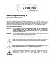
CEDES Installation and Operation Manual Bedienungsanleitung Manuel d'installation et d'utilisation IMS 100 Door closing protection with IMS 100 English Deutsch Français Maximizing door safety and comfort! RoHS IMPORTANT NOTE FOLLOW THE INSTRUCTIONS GIVEN IN THIS MANUAL CAREFULLY. FAILURE TO DO SO MAY CAUSE CUSTOMER COMPLAINTS AND SERIOUS CALL BACKS. KEEP INSTRUCTION MANUAL ON SITE. th © CEDES Version 3.1 / 10 April 2014 Part No. 106 854 Installation and Operation Manual IMS 100 IMPORTANT NOTICE THE IMS 100 MUST BE USED IN CONJUNCTION WITH A DOOR PROTECTION SYSTEM (E.G. LIGHT CURTAIN, MECHANICAL EDGE, ETC.). WHEN THE IMS 100 IS USED WITH THESE DEVICES, IT IS THE RESPONSIBILITY OF THE INSTALLER TO ENSURE THAT, ON COMPLETION, THE INSTALLATION COMPLIES WITH ALL THE RELEVANT CODES AND REGULATIONS THAT PERTAIN TO INFRARED AND PHOTOELECTRIC DOOR PROTECTION DEVICES! FAIL SAFE OPERATION: BECAUSE DOOR SYSTEM DESIGNS ARE NOT INHERENTLY FAIL SAFE, THERE ARE RARE SITUATIONS WHEN DOORS CAN CLOSE, EVEN WITH AN OBSTACLE OR PERSON PRESENT. THEREFORE, THERE MUST BE, BY CODE, OTHER SAFETY MEANS TO PREVENT PASSENGERS FROM BEING HURT BY THE ELEVATOR DOORS. DANGEROUS SITUATIONS, SUCH AS DESCRIBED, SHOULD BE DETECTED BY THE ELEVATOR CONTROL SYSTEM, WHICH, IN TURN, SHOULD CAUSE THE ELEVATOR TO BE TAKEN OUT OF SERVICE. IN GENERAL, DOOR PROTECTION SYSTEMS CANNOT PROVIDE ABSOLUTE SAFETY FOR ELEVATOR PASSENGERS PASSING THROUGH THE DOORWAY. THEY CANNOT BE USED AS FAIL-SAFE DEVICES OF THE DOOR MECHANISM. THIS SAFETY FUNCTION MUST BE PROVIDED BY A FAIL-SAFE FORCE AND KINETIC ENERGY LIMITER. DO NOT USE THIS PRODUCT FOR THE PROTECTION OF DANGEROUS MACHINERY OR IN EXPLOSIVE ATMOSPHERES OR RADIOACTIVE ENVIRONMENTS! USE ONLY SPECIFIC AND APPROVED TYPES OF SAFETY DEVICES FOR SUCH APPLICATIONS, OTHERWISE SERIOUS INJURY OR DEATH OF PERSONNEL MAY OCCUR! WARNING DOOR SENSOR DEVICES CAN ONLY ACHIEVE THEIR GIVEN FUNCTION, IF THE INSTRUCTIONS GIVEN IN THIS INSTRUCTION MANUAL AND THE DOCUMENTS MENTIONED WITHIN ARE FOLLOWED EXACTLY, AS WELL AS COMPLYING WITH APPLICABLE CODES AND REGULATIONS AT THE TIME OF INSTALLATION. THE INSTALLER AND/OR SYSTEM INTEGRATOR IS FULLY RESPONSIBLE FOR THE SAFE INSTALLATION AND INTEGRATION OF THIS PRODUCT. THIS INSTRUCTION MANUAL MUST BE KEPT ACCESSIBLE TOGETHER WITH THE OTHER ELEVATOR DOCUMENTATION DURING ITS ENTIRE LIFE CYCLE FOR ALL PERSONNEL RESPONSIBLE FOR ASSEMBLY, INSTALLATION, OPERATION AND MAINTENANCE. 2 www.cedes.com © CEDES/April 2014 Installation and Operation Manual Content 1. Introduction ................................3 2. Delivery content ..........................4 3. 3.1. 3.2. Mechanical installation ...............4 Switch OFF main power ........................... 4 Mechanical installation of IMS 100 ........... 5 3.2.1. 3.2.2. 3.2.3. 3.3. Electrical installation ................................ 8 3.3.1. 3.3.2. 4. Possible sensor positions ....................... 5 Installation of surface mounted sensor ... 6 Installation of flush mounted sensor ....... 7 Wiring .................................................. 8 Integrating IMS 100 .............................. 8 3.4. Power-up and test for proper function ....... 9 4.1. 4.2. 4.3. 4.4. Trouble shooting ....................... 10 LED indicators ....................................... 10 Random door openings ......................... 10 Removal of mounting clips ..................... 11 Problem checklist ................................... 11 5. Technical data .......................... 12 6. Certificate of compliance / Konformitätserklärung / Certificat de conformité ............. 35 7. CSA certificate / CSA-Zertifikat / Certificat CSA ........................... 36 © CEDES/April 2014 www.cedes.com IMS 100 1. Introduction The IMS 100 sensor is used to enhance elevator door protection systems by providing sensor detection in front of the elevator cab entrance. It is used with existing two-dimensional (2D) elevator door protection systems such as light curtains, single-beam sensors or mechanical edges to provide three-dimensional (3D) protection. The IMS 100 can be used for new elevator installations or for modernization of existing elevator systems. As an extension to existing door-protection devices, the purpose of the IMS 100 sensor is to monitor the entrance area of the elevator door for people or objects entering the elevator cab. By using “Time of Flight” (TOF) technology, the IMS 100 sensor can detect the difference between a person or object approaching the elevator cab and a stationary person or object in the elevator cab entrance area. The sensor's compact, low profile housing is optimized for difficult mounting locations, including narrow elevator cab transoms. When the elevator cab door opens, the IMS 100 quickly acquires a reference image of the elevator cab entrance area. This reference image is then compared to the sensor's current image. The IMS 100 behaves similarly to other door protection systems (e.g. light curtains). When the sensor is clear of moving person(s) or object(s), the semiconductor-based output will be active (high, e.g. 24 VDC). When a moving person or object is detected within the sensor's field of view (approximately 900 mm wide by 200 mm depth), the semiconductor output will transition to inactive (low, e.g. 0 VDC). The IMS 100 can also be configured so that the semiconductor output will automatically transition to active (high, e.g. 24 VDC) after a fixed 18second timer has expired (e.g. for nudging). 3 Installation and Operation Manual IMS 100 2. Delivery content The IMS 100 system consists of the following components: 1 4 5 3 6 7 2 Figure 1: Typical IMS 100 system components Figure 2: Power line converter Parts information for typical IMS system components - P/N 106 834 P/N 104 153 P/N 106 852 (30°) or P/N 113 236 (35°); model dependent P/N 108 176 P/N 108 177, comprises 4 clips, 2 screws, reflective tape P/N 106 854 P/N 106 666 or P/N 111 014; model dependent IMS 100 sensor Connection cable Mounting bracket IMS 100, flush mounting Mounting box IMS 100, surface mounting IMS 100 accessories kit Installation and operation manual Power line converter 85 …265 VAC Important: Integrating the CEDES IMS 100 sensor into a new or existing door protection system can be accomplished in several ways depending on the elevator control system requirements. The following sections provide examples for incorporating the IMS 100 into an existing system. The contents of each delivery depend on the system ordered. Should you have any queries regarding the contents of this delivery, or if you require application assistance, please contact CEDES or your local distributor. 3. Mechanical installation The installation should be done in the following order: 1. Switch off power and mark clearly that this elevator is out of service 2. Mechanical installation of the IMS 100 3. Electrical installation and integration of IMS 100 4. Power-up and test for proper function 3.1. Switch OFF main power For your own safety, turn the power off before you start working on the elevator! Clearly mark that this elevator is out of service. Keep the working area closed to the public all the times. 4 www.cedes.com © CEDES/April 2014 Installation and Operation Manual IMS 100 3.2. Mechanical installation of IMS 100 3.2.1. Possible sensor positions Center opening car door The sensor is placed in the door frame in the center of the door opening. Orientation: Cable going out on slam post side or toward center of cab entrance opening Center surface Center flush Side opening car door The sensor is placed in the door frame as near to the slam post as possible. Orientation: The sensor must be mounted with the cable outlet facing the door jamb. Side surface © CEDES/April 2014 www.cedes.com Side flush 5 Installation and Operation Manual IMS 100 3.2.2. Installation of surface mounted sensor The sensor has to be installed on the elevator cab transom. Step 1 Action Drill two 3.2 mm (1/8 inch) holes for the sensor box (1) with 100 mm distance into the elevator cab transom (2). Illustration / note (all dimensions in mm) Drill a 10 mm (3/8 inch) hole into the elevator cab transom (2) for the sensor cable. For side-opening doors: Keep a distance of 22 mm from the corner of the doorway. 2 3 Mount the sensor box (1) with the two 3.5 mm self-tapping screws (3) on the elevator cab transom (2). Snap the sensor (4) into the mounting bracket (5). 2 1 4 5 Align the sensor to the lobby. 2 1 3 4 Angle: 0 ... 30° 5 6 Angle: 0 ... 35° 4 6 Route cable up through the 10 mm hole (3/8 inch) in the elevator cab transom. Important note: Slide the sensor (4) with the mounting Observe for side opening doors. bracket (5) into the hole and fix it with the The sensor must be mounted with the cable outlet facing the door two mounting clips (6). jamb. For removal of the clips please refer to section 4.3 www.cedes.com © CEDES/April 2014 Installation and Operation Manual IMS 100 3.2.3. Installation of flush mounted sensor Step 1 2 Action Cut a square shape of 29 x 111 mm out of the elevator cab transom (1). Keep the distance to the edge (2) of the elevator cab transom, hall side, as short as possible. → The MINIMUM distance is 17 mm → The MAXIMUM distance is 250 mm Drill two 4.7 mm (3/16 inch) diameter holes for the mounting bracket (4) into the elevator cab transom (1) with 120 mm distance on the centerline (CL) of the shape. Keep the minimum distance of 7 mm from the corner of the doorway. Illustration / note (all dimensions in mm) 1 CL 2 Hall Side Snap the sensor (3) into the mounting bracket (5). 3 4 Align the sensor to the lobby. 3 4 Angle: 0 ... 30° 5 Angle: 0 ... 35° 3 Route cable up through the hole in the elevator cab transom. Slide the sensor Important note: (3) with the mounting bracket (4) into the Observe for side opening doors. hole and fix it with the two mounting clips sensor must be mounted with the cable outlet facing the door The (5). jamb. For removal of the clips please refer to section 4.3 © CEDES/April 2014 www.cedes.com 7 Installation and Operation Manual IMS 100 Timeout function 3.3. Electrical installation 3.3.1. Wiring Make sure that the power supply voltage available for IMS 100 is +24 VDC ±10%. The power supply has to provide at least 250 mA for proper operation. Important note: The Universal Power Supply (CEDES P/N 103 600) cannot be used as Power Supply for the IMS 100. The min. required current consumption of IMS 100 is 200 mA. Use the power line converter (CEDES P/N 106 666 or P/N 111 014) or any 24 V power supply with at least 6 W available on the market. Cable connection of IMS 100 Cable color Brown Blue Black White Connected to USP = +24 VDC ±10% GND (0 V) Output (Door re-open signal) Timeout Selector IMS 100 on PNP load USP (brown) µC Out (black) Load iPNP PNP Output logic 3D Object No object 0 V (blue) Timeout Selector (white) Output LED (Black connector) (Red) Low, 0 VDC LED on High, 24 VDC LED off When a moving person or object is detected within the sensor's field of view (approximately 900 mm wide by 200 mm depth), the semiconductor output will transition to inactive (low, e.g. 0 VDC). The IMS 100 can also be configured so that the semiconductor output will automatically transition to active (high, e.g. 24 VDC) after a fixed 18-second timer has expired (e.g. for nudging). The timeout setting can be changed based on the signal connected to the timeout selector (white conductor) as shown in the following table. Timeout selector connection (white Timeout conductor) has to be connected setting either/or Connected to USP 18 s * Connected to 0 VDC (GND) Infinity Important note: * The timer begins to count after the first sensor triggering. After this time the sensor will be disabled until the next door opening. Important note: IMS 100 meets all standards for resistance to electromagnetic interference (EMI). However, it is prudent to guard against interference Therefore, do not guide the connection cables close to cables carrying high voltage and/or high current. The IMS 100 cables should also be mounted as far away as possible from the door drive motor or motor inverter (variable voltage, variable frequency drives) to avoid EMI problems. 3.3.2. Integrating IMS 100 Integrating the IMS 100 sensor into a new or existing door protection system can be accomplished in several ways depending on the elevator control system requirements. The following block diagrams outline examples for incorporating the IMS 100 into an existing system. Several other methods for integrating the IMS 100 with existing systems are also possible. Should you have any questions, or if you require application assistance, please contact CEDES or your local distributor. Important note: The IMS 100 detects moving persons and objects. The recalibration time of IMS 100 is set to 1.5 s. This means a moving object that becomes static for more than 1.5 s is then ignored by the IMS 100. 8 www.cedes.com © CEDES/April 2014 Installation and Operation Manual IMS 100 sensor Output type: 24V, PNP IMS 100 Elevator door protection Output type: Semiconductor / Relay C E D E S power line converter with relay output (P/N 106 666 or P/N 111 014) provides a simple means of converting 85 … 265 VAC input power to 24 VDC. This is required to power the door protection light curtain or the IMS 100 while, at the same time, converting semiconductor outputs (NPN or PNP) to potentialfree (relay) contacts. Switching Power line Power converter Supply To Elevator Control 3.4. Power-up and test for proper function Once the IMS 100 and associated door protection system have been installed and wired in accordance with your elevator control system requirements, turn the power on and verify that the system operates as expected. When the CEDES power line converter is connected to 85 … 265 VAC, the green LED will be illuminated to indicate that 24 VDC power is present for powering the IMS 100 sensor and that the input voltage to the power supply is greater than 85 VAC. The IMS 100 has several IR-LEDs that are used for infrared illumination of the area. If you look directly at the sensor when it is under power, these LEDs will be flashing constantly. © CEDES/April 2014 Necessary accessories Power line converter www.cedes.com Additional change-over-relay is needed whenever the existing logic of the light curtain was NC, i.e. whenever the elevator controller needs a high level for “No object”. If the existing light curtain already has a relay output, you simply have to make a logical AND conjunction of the two relay outputs. The IMS 100 also has a single red LED that provides output status information (see 4.1). When this red LED is illuminated (i.e. ON), the IMS 100 has detected a moving person or object and the output (black conductor) will be inactive (low, e.g. 0 VDC). When this LED is not illuminated (i.e. OFF), the IMS 100 has detected no person or object and the output (black conductor) will be active (high, e.g. 24 VDC / USP). See Section 4, Troubleshooting for additional information regarding other LED states. Important note: The IMS 100 is an intelligent sensor that bypasses itself during door closure. There is no need for an additional sensor(s) for door recognition. When installed correctly, the IMS 100 remains active (i.e. not bypassed) until approximately 100 ... 150 mm prior to door closure. 9 Installation and Operation Manual IMS 100 4. Troubless h o o t i n g 4.1. LED indicators l = LED on Red LED Indication ¡ ¡ = LED off ¥ = LED flashing - No power connected or - No object detected or - Sleeping mode (Reduced scan frequency) l Object detected in IMS 100 protection area ¥ Slow flashing: 1 2 - Door mode à door has been recognized - Sensor keeps flashing as long door is closed Fast flashing: - Sensor in timeout (see Section 3.3.1) - Sensor flashing until door recognition (door mode) Figure 3: Position of LED (1) and sensitive receiver part (2) 4.2. Random door openings In case the elevator door is made of glass or a shiny material (e.g. mirror), the door may not be detected by the sensor during closure. For these applications, place a piece of reflective tape on the inner side of the elevator cab door that passes in front of the sensor as the door closes (see figure 4 and 5). IMS 100 sensor Door frame Y Reflective tape x Inner door of the cabin Figure 4: Reflective tape for side opening door Figure 5: Reflective tape for center opening door To ensure the reflective tape is positioned within the sensor’s field of view , the Y distance measurement is used. For 30° mounting brackets, use the following formula: Distance Y = 1.7 * horizontal distance x For 35° mounting brackets, use the following formula: Distance Y = 1.4 * horizontal distance x 10 www.cedes.com © CEDES/April 2014 Installation and Operation Manual IMS 100 4.3. Removal of mounting clips Use a flat blade screwdriver (2) as shown to remove the mounting clips (1) from the sensor holder. The clips cannot be reused. A second pair of mounting clips (1) is included with each IMS 100. Spare mounting clips are available. 2 1 4.4. Problem checklist Problem / Situation What to check? No function, door open Power supply good? Power wire broken? Defective power line converter? Section 3.3.2 Door constantly open Are the light curtain and IMS 100 connected correctly? Is the IMS 100 aligned towards the hall? Is the relay connected correctly (COM, NO, NC)? Position of IMS 100 inside elevator cab transom within the tolerance? Does IMS 100 sensor optically influence the light curtain? Dirty sensors? Excessive EMC interference e.g. from door drive or fluorescent lamps? Section 3.3.2 Section 3 Please refer to light curtain manual Door closing although person or object in the IMS 100 detection area Are the light curtain and IMS 100 connected correctly? Is the relay connected correctly (COM, NO, NC)? Is the alignment done properly? Position of IMS 100 inside elevator cab transom within the tolerance? Dirty sensors or vision shields? Excessive EMC interference e.g. from door drive or fluorescent lamps? Section 3.3.2 Section 3 Section 4.2 Please refer to light curtain manual Random door openings No person or object moving in the IMS 100 detection area © CEDES/April 2014 Refer to Do the sensors influence each other? Dirty sensors or vision shields? Excessive EMC interference e.g. from door drive or fluorescent lamps? Damaged cable to the sensors, check for break in the cables by moving the cable by hand? Interference with other infrared sensors with the receiver directly or via mirroring from shiny surfaces? Sufficient current supply from the used power supply (> 200 mA)? www.cedes.com Section 3.3.2 Section 3 Section 4.2 Please refer to light curtain manual 11 Installation and Operation Manual IMS 100 5. Technical data Detection height 0.6 ... 2.5 m Detection area at 2 m 200 mm x 900 mm Min. object detection at 2.5 m 50 mm Wave length IR 850 nm Mechanical Dimensions (w x h x d) Housing material Enclosure rating Temperature range Mechanical adjustment range 102 x 27 x 23 mm Aluminum, Polycarbonate (PC) IP54 -20 °C … +45 °C 30° or 35° (model dependent) Electrical Power supply USP Max. current consumption at 24 VDC Output Max. output load Output logic Response time Max. optical illumination LED power Max. recalibration time 24 VDC ±10% 200 mA PNP 50 mA, 100 nF LOW = object, HIGH = no object 350 ms Object detected No object detected 0.5 W 1.5 s Connection cable and electrical connection Length sensor cable Length connection cable Diameter Material Connection Wires brown blue black white 0.5 m 2.8 m Ø 3.5 mm PVC, black M8, 4-pin AWG26 USP GND (0 V) Output (PNP) Time-out selector (18 s or infinity) General Eye Safety EMC emission EMC immunity Vibration Shock Cable durability Certificates RoHS EN 62471: 2008 EN 50081-1:1992, EN 12015:2004 EN 50081-2:1994, EN 12016:2004 IEC 60068-2-6:2007 IEC 60068-2-27:2008 IEC 60227-2:2003 CE, CSA 2011/65/EU Optical Indication LED (red): LED on LED off 12 www.cedes.com © CEDES/April 2014 Bedienungsanleitung IMS 100 WICHTIGER HINWEIS HALTEN SIE SICH GENAU AN DIE ANWEISUNGEN IN DIESER ANLEITUNG. NICHTBEACHTEN KANN KUNDENREKLAMATIONEN UND RÜCKRUFMASSNAHMEN NACH SICH ZIEHEN. BEWAHREN SIE DIESE ANLEITUNG IMMER IN DER NÄHE DER ANLAGE AUF. WICHTIGE INFORMATIONEN DER IMS 100 DARF NUR IN VERBINDUNG MIT EINEM TÜRSICHERUNGSSYSTEM (Z. B. LICHTVORHANG, MECHANISCHE FLANKE O. Ä.) VERWENDET WERDEN. WIRD IMS 100 ZUSAMMEN MIT DIESEN EINRICHTUNGEN VERWENDET, LIEGT ES IN DER VERANTWORTUNG DES MONTEURS, DASS DIE MONTAGE ALLEN RELEVANTEN GESETZEN UND VORSCHRIFTEN ZU INFRAROTUND PHOTOELEKTRISCHEN TÜRSICHERUNGSVORRICHTUNGEN ENTSPRICHT! AUSFALLSICHERER BETRIEB: DA TÜRSYSTEME NICHT GRUNDSÄTZLICH AUSFALLSICHER SIND, KANN ES IN SELTENEN FÄLLEN VORKOMMEN, DASS TÜREN SCHLIESSEN, OBWOHL SICH EINE PERSON ODER EIN GEGENSTAND DAZWISCHEN BEFINDET. DAHER SIND ZUSÄTZLICHE SICHERHEITSVORRICHTUNGEN VORGESCHRIEBEN, DIE VERHINDERN, DASS AUFZUGBENUTZER DURCH DIE AUFZUGTÜREN ZU SCHADEN KOMMEN. DERARTIGE GEFAHRENSITUATIONEN MUSS DIE AUFZUGSTEUERUNG ERKENNEN UND DEN BETREFFENDEN AUFZUG AUSSER BETRIEB NEHMEN. GRUNDSÄTZLICH KÖNNEN TÜRSICHERUNGSSYSTEME KEINE ABSOLUTE SICHERHEIT FÜR AUFZUGBENUTZER BIETEN. SIE KÖNNEN NICHT ALS AUSFALLSICHERE KOMPONENTEN DES TÜRMECHANISMUS EINGESETZT WERDEN. DIESE SICHERHEITSFUNKTION MUSS DURCH AUSFALLSICHERE SCHLIESSKRAFTBEGRENZER GEGEBEN SEIN. IMS 100 DARF NICHT FÜR DIE ABSICHERUNG VON GEFÄHRLICHEN MASCHINEN ODER FÜR ANLAGEN IN EXPLOSIVER ATMOSPHÄRE ODER FÜR ANLAGEN IN RADIOAKTIVER UMGEBUNG EINGESETZT WERDEN. FÜR SOLCHE ANWENDUNGEN DÜRFEN NUR DAFÜR SPEZIFIZIERTE UND FREIGEGEBENE SICHERHEITSPRODUKTE VERWENDET WERDEN, ANDERENFALLS KÖNNEN SCHWERE VERLETZUNGEN ODER TOD DIE FOLGE SEIN! VORSICHT TÜRSENSORVORRICHTUNGEN ERFÜLLEN IHRE FUNKTION NUR DANN, WENN DIE ANWEISUNGEN IN DIESER ANLEITUNG UND DEN DARIN GENANNTEN DOKUMENTEN SOWIE DIE ZUM ZEITPUNKT DES EINBAUS GELTENDER GESETZE UND VORSCHRIFTEN GENAU BEFOLGT WERDEN. DER MONTEUR UND/ODER SYSTEMINTEGRATOR TRÄGT DIE VOLLE VERANTWORTUNG FÜR DEN SICHEREN EINBAU DIESES PRODUKTS. DIESE ANLEITUNG MUSS ZUSAMMEN MIT DER ÜBRIGEN AUFZUGDOKUMENTATION WÄHREND DER GESAMTEN LEBENSDAUER DER ANLAGE IN REICHWEITE DER FÜR MONTAGE, BETRIEB UND WARTUNG ZUSTÄNDIGEN MITARBEITER AUFBEWAHRT WERDEN. © CEDES/April 2014 www.cedes.com 13 Bedienungsanleitung IMS 100 Inhalt 1 . E i n l e i t u n g . . . . . . . . . . . . . . . . . . . . . . . . . . . . . . . . . . 1 4 2 . L i e f e r u m f a n g . . . . . . . . . . . . . . . . . . . . . . . . . . . . . . 1 5 3 . M o n t a g e . . . . . . . . . . . . . . . . . . . . . . . . . . . . . . . . . . . . 1 5 3.1. Hauptstromversorgung abschalten .......... 15 3.2. Einbau des IMS 100 ............................... 16 3.2.1. 3.2.2. 3.2.3. Mögliche Sensorpositionen .................. 16 Aufputzmontage ................................. 17 Hinterwandmontage ........................... 18 3.3. Elektrischer Anschluss ............................. 19 3.3.1. 3.3.2. Verkabelung ....................................... 19 Einbindung des IMS 100 ..................... 19 3.4. Einschalten und Funktionsprüfung ........... 20 1. Einleitung Durch eine zusätzliche Sensorerfassung im Bereich vor dem Eingang der Aufzugkabine sorgt der Sensor IMS 100 bei Aufzugtürsicherungssystemen für ein noch höheres Mass an Sicherheit. Er wird in bestehende zweidimensionale (2D) Aufzugtürsicherungssysteme wie Lichtvorhänge, Einzellichtschranken oder mechanische Flanken integriert, um einen drei-dimensionalen (3D) Schutz zu bieten. IMS 100 lässt sich sowohl für neu eingebaute Aufzuganlagen als auch für die Modernisierung bereits bestehender Anlagen verwenden. 4 . Fehlerbehebung . . . . . . . . . . . . . . . . . . . . . . . . . . . . 2 1 4.1. LED-Anzeigen......................................... 21 4.2. Aufzugstür reversiert ohne Objekt ............ 21 4.3. Montageclips entfernen ........................... 22 4.4. Problem-Checkliste ................................. 22 Als Erweiterung bestehender Türsicherungsvorrichtungen dient der Sensor IMS 100 dazu, Personen oder Objekte im Eingangsbereich einer Aufzugskabine zu erkennen. Das verwendete „Time of Flight“-Prinzip (TOF) ermöglicht es, zwischen bewegten oder statischen Personen oder Objekten zu unterscheiden. Das kompakte und schmale Gehäuse des Sensors eignet sich optimal für den Einbau bei engen Platzverhältnissen. 7 . C S A c e r t i f i c a t e / C S A - Z e r t i f i k a t / C e r t i f i c a t C S A . . . . . . . . . . . . . . . . . . . . . . . . . . . . . 3 6 Wenn sich die Kabinentür öffnet, kalibriert sich der IMS 100 Sensor sofort auf die Verhältnisse im Kabineneingangsbereich. Veränderungen zum Referenzbild werden folglich sofort erkannt. IMS 100 verhält sich ähnlich wie andere Türsicherungssysteme (z. B. Lichtvorhänge). Wenn der Sensor keine sich bewegenden Personen oder Objekte erfasst, ist der Halbleiter-Ausgang aktiv („high“, z. B. 24 VDC). Wird eine sich bewegende Person oder ein Objekt im Sensorfeld (ca. 900 mm breit und 200 mm tief) erfasst, geht der Halbleiter-Ausgang in den inaktiven Zustand über („low“, z.B. 0 VDC). IMS 100 lässt sich auch so konfigurieren, dass der Halbleiter-Ausgang nach Ablauf eines festgelegten 18-Sekunden-Intervalls automatisch auf aktiv („high“, z. B. 24 VDC) umschaltet. 5 . T e c h n i s c h e D a t e n . . . . . . . . . . . . . . . . . . . . . . . . 2 3 6 . C e r t i f i c a t e o f c o m p l i a n c e / Konformitätserklärung / Certificat d e c o n f o r m i t é . . . . . . . . . . . . . . . . . . . . . . . . . . . . . 3 5 14 www.cedes.com © CEDES/April 2014 Bedienungsanleitung 2. IMS 100 Lieferumfang Das IMS 100 System besteht aus folgenden Komponenten: 1 4 5 3 6 7 2 Abbildung 1: Typische IMS 100 Systemkomponenten Abbildung 2: Schaltnetzteil Artikelinformationen für die typischen Systemkomponenten - P/N 106 834 P/N 104 153 P/N 106 852 (30°), P/N 113 236 (35°) P/N 108 176 P/N 108 177, enthält 4 Clips, 2 Schrauben, Reflektorfolie P/N 106 854 P/N 106 666 oder P/N 111 014, modellabhängig IMS 100 Sensor Anschlusskabel Montagebügel IMS 100, Hinterwandmontage Montagebox IMS 100, Aufputzmontage Beipack IMS 100 Bedienungsanleitung Schaltnetzteil 85 …265 VAC Wichtig: Abhängig von den Anforderungen der jeweiligen Aufzugsteuerung lässt sich der CEDES IMS 100 Sensor auf verschiedene Art und Weise in eine neue oder bereits bestehende Aufzugskabine integrieren. In den folgenden Abschnitten finden Sie Beispiele für den Einbau des IMS 100 in ein bereits bestehendes System. Der Lieferumfang kann je nach Art des bestellten Systems variieren. Wenn Sie Fragen zum Lieferumfang haben oder Hilfe bei der Anwendung benötigen, wenden Sie sich bitte an CEDES oder an Ihren Händler vor Ort. 3. Montage Bitte montieren Sie IMS 100 in der folgenden Reihenfolge: 1. Stromversorgung abschalten und Aufzug eindeutig als „Ausser Betrieb“ kennzeichnen 2. Einbau des IMS 100 3. Elektroinstallation und Integration des IMS 100 4. Einschalten und Funktionsprüfung 3.1. Hauptstromversorgung abschalten Schalten Sie zu Ihrer eigenen Sicherheit die Versorgungsspannung aus, bevor Sie mit den Arbeiten am Aufzug beginnen. Kennzeichnen Sie den Aufzug eindeutig als „Ausser Betrieb“. Der Arbeitsbereich muss stets abgesperrt sein. © CEDES/April 2014 www.cedes.com 15 Bedienungsanleitung IMS 100 3.2. Einbau des IMS 100 3.2.1. Mögliche Sensorpositionen Zentral öffnende Kabinentüren Der Sensor wird im Türrahmen in der Mitte der Türöffnung platziert. Ausrichtung: Kabelaustritt auf beiden Seiten möglich Aufputzmontage (in der Mitte) Hinterwandmontage (in der Mitte) Aufputzmontage (seitlich) Hinterwandmontage (seitlich) Seitlich öffnende Kabinentüren Der Sensor wird seitlich, so nah wie möglich am Anschlag, in den Türrahmen montiert. Ausrichtung: Kabelaustritt in Richtung Türpfosten montieren 16 www.cedes.com © CEDES/April 2014 Bedienungsanleitung IMS 100 3.2.2. Aufputzmontage Der Sensor ist auf die Türzarge (Kämpfer) der Kabine zu montieren. Schritt Massnahme 1 Bohren Sie im Abstand von 100 mm zwei Löcher von 3.2 mm für das Aufputzgehäuse (1) in die Kabinentürzarge (2). Bohren Sie ein Loch von 10 mm in die Türzarge (2) für das Sensorkabel. Bei seitlich öffnenden Türen: Achten Sie auf einen Abstand von 22 mm von der Ecke der Türöffnung. 2 3 Befestigen Sie das Aufputzgehäuse (1) mit den beiden 3.5 mm Blechschrauben (3) an der Türzarge (2). Lassen Sie den Sensor (4) in den Montagebügel (5). Abbildung / Bemerkung (alle Abmessungen in mm) 2 1 4 5 Richten Sie den Sensor auf den Vorraum aus. 2 1 3 4 Winkel: 0 ... 30° 5 6 Winkel: 0 ... 35° 4 Führen Sie das Kabel durch das 10 mm Loch in der Türzarge. Schieben Sie den Wichtiger Hinweis: Sensor (4) mit dem Montagebügel (5) in das Loch und befestigen Sie ihn mit Bei seitlich öffnenden Türen ist zu beachten, dass der Kabelaustritt des Sensors IMS 100 in Richtung Türpfoszwei Montage-Clips (6). Zur Entfernung der Clips lesen Sie bitte ten orientiert ist und in genau dieser Position montiert werden. Abschnitt 4.3 © CEDES/April 2014 www.cedes.com 17 Bedienungsanleitung IMS 100 3.2.3. Hinterwandmontage Schritt Massnahme Schneiden Sie eine viereckige Öffnung 1 von 29 x 111 mm in die Kabinentürzarge (1). Achten Sie auf einen möglichst geringen Abstand zur flurseitigen Kante der Türzarge (2). → Der Mindestabstand beträgt 17 mm. → Der Höchstabstand beträgt 250 mm. Bohren Sie im Abstand von 120 mm auf der Mittellinie (CL) zwei Löcher von 4,7 mm für den Montagebügel (4) in die Türzarge (1). Achten Sie auf den Mindestabstand von 7 mm zur Ecke der Türöffnung. 2 Lassen Sie den Sensor (3) in den Montagebügel (4). Abbildung / Bemerkung (alle Abmessungen in mm) CL 1 2 Flurseite 3 4 Richten Sie den Sensor auf den Vorraum aus. 3 4 Winkel: 0 ... 30° 5 Winkel: 0 ... 35° 3 18 Wichtiger Hinweis: Führen Sie das Kabel aufwärts durch Bei seitlich öffnenden Türen ist zu beachten, das viereckige Loch in der Türzarge. dass der Kabelaustritt des Sensors IMS 100 in Richtung TürpfosSchieben Sie den Sensor (3) mit dem ten orientiert ist und in genau dieser Position montiert werden. Montagebügel (4) in das Loch und befestigen Sie ihn mit zwei Montage-Clips (5). Zur Entfernung der Clips lesen Sie bitte Abschnitt 4.3 www.cedes.com © CEDES/April 2014 Bedienungsanleitung IMS 100 3.3. Elektrischer Anschluss Time-out Funktion 3.3.1. Verkabelung Wird eine sich bewegende Person oder ein Objekt im Sensorfeld (ca. 900 mm breit und 200 mm tief) erfasst, geht der Halbleiter-Ausgang in den inaktiven Zustand über („low“, z. B. 0 VDC). Stellen Sie sicher, dass die verfügbare Versorgungsspannung für IMS 100 bei +24 VDC ±10 % liegt. Für einen einwandfreien Betrieb muss die Spannungsversorgung mindestens 250 mA liefern. Wichtiger Hinweis: Das Universalnetzteil (CEDES P/N 103 600) kann nicht als Netzteil für den IMS 100 verwendet werden. Die minimal erforderliche Stromaufnahme des IMS 100 beträgt 200 mA. Verwenden Sie das Schaltnetzteil (CEDES P/N 106 666 oder P/N 111 014) oder ein anderes handelsübliches 24V-Netzteil mit einer Mindestleistung von 6 W. Anschluss an USP = +24 VDC ±10 % GND (0 V) Ausgang (Signal “Tür wieder öffnen) Einstellung Time-out IMS 100: PNP-Anschluss USP (braun) µC Last iPNP PNP Ausgang (schwarz) 0 V (blau) Time-out (weiss) Ausgangslogik 3D Objekt Kein Objekt Ausgang (schwarze Ader) Low, 0 VDC LED (rot) LED an High, 24 VDC LED aus Wichtiger Hinweis: IMS 100 detektiert sich bewegende Personen und Objekte. Die Nachkalibrierungszeit des IMS 100 ist auf 1.5 s gesetzt. Das heisst, sobald sich ein Objekt länger als 1.5 s nicht bewegt, wird es ausgeblendet. © CEDES/April 2014 IMS 100 kann mit zwei Zeitmodi betrieben werden. Diese werden mit der Beschaltung des Time-out Eingangs (weisse Ader) gewählt. Der Time-out Eingang muss entweder/oder angeschlossen werden (siehe Tabelle): Anschluss Time-out Selector Time-out (weisse Ader) Einstellung Kabelanschlüsse - IMS 100 Kabelfarbe Braun Blau Schwarz Weiss IMS 100 lässt sich auch so konfigurieren, dass der Halbleiter-Ausgang nach Ablauf eines festgelegten 18-Sekunden-Intervalls automatisch auf aktiv („high“, z. B. 24 VDC) umschaltet. www.cedes.com Anschluss an USP 18 s * Anschluss an 0 VDC (GND) Unendlich Wichtiger Hinweis: * Der Timer beginnt mit der Zählung ab der ersten Sensorauslösung. Nach dieser Zeit wird der Sensor bis zum nächsten Öffnen der Tür abgeschaltet. Wichtiger Hinweis: IMS 100 erfüllt sämtliche Normen hinsichtlich elektromagnetischer Störungen (EMV), aber ein Schutz gegen Störungen ist dennoch zu empfehlen. Führen Sie daher die Anschlusskabel nicht zu nahe an Hochspannungs- und/oder Starkstromkabeln entlang. Um elektromagnetische Störungen zu vermeiden, sollten Sie die Kabel des IMS 100 ebenfalls nicht zu nahe am Motor des Türantriebs bzw. am Leistungsteil der Türsteuerung (VVVFAntriebe) entlang führen. 3.3.2. Einbindung des IMS 100 Abhängig von den Anforderungen der jeweiligen Aufzugsteuerung lässt sich der IMS 100 Sensor auf verschiedene Art und Weise in eine neue oder bereits bestehende Aufzugskabine integrieren. Im folgenden Blockschaltbild finden Sie ein Beispiel für den Einbau des IMS 100 in ein bereits bestehendes System. Es stehen auch verschiedene andere Verfahren zur Integration des IMS 100 in bereits vorhandene Systeme zur Verfügung. Wenn Sie Fragen haben oder Hilfe bei der Anwendung benötigen, wenden Sie sich bitte an CEDES oder an Ihren Händler vor Ort. 19 Bedienungsanleitung IMS 100 IMS 100 Sensor Ausgang: 24V, PNP Sicherung der Aufzugstür Ausgang: Halbleiter / Relais C E D E S Schaltnetzteile mit Ausgangsrelais (P/N 106 666 oder P/N 111 014) ermöglichen auf einfache Weise die Umwandlung von 85 … 265 VAC Eingangsspannung in die zur Versorgung eines Türsicherungslichtvorhangs oder des IMS 100 erforderlichen 24 VDC sowie die Umwandlung von Halbleiterausgängen (NPN oder PNP) in potentialfreie (Relais-) Kontakte. Schaltnetzteil Zur Aufzugssteuerung 3.4. Einschalten und Funktionsprüfung Sobald IMS 100 und das dazugehörige Türsicherungssystem gemäss Ihren Aufzugsteuerungsanforderungen montiert und verkabelt sind, schalten Sie den Strom ein und überprüfen Sie, ob der Sensor korrekt funktioniert. Wenn das CEDES Schaltnetzteil an 85 ... 265 VAC angeschlossen ist, leuchtet die grüne LED und zeigt an, dass 24 VDC für den Betrieb des IMS 100 Sensors anliegen und die Eingangsspannung zum Netzteil höher ist als 85 VAC. IMS 100 verfügt über mehrere IR-LED zur InfrarotBeleuchtung des Bereichs. Diese sind schwach durch die Abdeckung sichtbar. 20 Notwendiges Zubehör Schaltnetzteil www.cedes.com Ein zusätzliches Umschaltrelais ist erforderlich, wenn es sich bei der bestehenden Logik des Lichtvorhangs um eine NC-Logik handelt, d. h. wenn die Aufzugssteuerung ein hohes Spannungssignal für die Meldung „kein Objekt“ benötigt. Verfügt der vorhandene Lichtvorhang bereits über ein Ausgangsrelais, ist lediglich eine logische UNDVerbindung der beiden Ausgangsrelais erforderlich. IMS 100 hat auch eine einzelne rote LED, die den Ausgangsstatus anzeigt. Wenn diese rote LED leuchtet (d. h. EIN), hat IMS 100 eine sich bewegende Person oder ein Objekt erfasst und der Ausgang (schwarzer Leiter) ist inaktiv („low“, z. B. 0 VDC). Wenn diese LED nicht leuchtet (d. h. AUS), hat der IMS 100 keine Personen oder Objekte erfasst und der Ausgang (schwarzer Leiter) ist aktiv („high“, z. B. 24 VDC / USP). Weitere Informationen zu anderen LEDStatus finden Sie unter „Fehlerbehebung“ (siehe Abschnitt 4) Wichtiger Hinweis: IMS 100 ist ein intelligenter Sensor, der sich bei geschlossener Tür selbst überbrückt. Eine zusätzliche Türerkennung ist nicht erforderlich. Bei ordnungsgemässer Montage bleibt IMS 100 bis ca. 100 ... 150 mm vor Türschliessung aktiv. © CEDES/April 2014 Bedienungsanleitung 4. IMS 100 Fehlerbehebung 4.1. LED-Anzeigen Rote LED Anzeige ¡ - Keine Netzspannung oder - kein Objekt erfasst oder - Ruhemodus (reduzierte Abtastfrequenz) l Objekt im IMS 100 Erfassungsbereich ¥ LED blinkt langsam: l = LED ein ¡ = LED aus ¥ = LED blinkt 1 2 Türmodus à Tür wurde erkannt - Sensor blinkt, solange Tür geschlossen ist LED blinkt schnell: - Sensor in Time-out (s. Kapitel 3.3.1) - Sensor blinkt bis zum Türmodus (Tür wurde erkannt) - Abbildung 3: Position LED (1) und des empfindlichen Empfänger (2) 4.2. Aufzugstür reversiert ohne Objekt Ist die Aufzugstür aus Glas oder einem spiegelndem Material, ist es möglich, dass der 3D-Sensor IMS 100 die Tür während der Schliessung nicht erkennt. Ist dies der Fall, kleben Sie die beiliegende Reflektorfolie auf die Innenseite der Aufzugskabine. Die Position der Folie ist oben, genau im Sichtfeld vom Sensor zu Positioniern (siehe Abbildung 4 und 5). IMS 100 Sensor Türzarge Y Reflektorfolie x Kabineninnentür Abbildung 4: Position der reflektierenden Folie - seitlich öffnende Tür Abbildung 5: Position der reflektierenden Folien - zentral öffnende Tür Um sicher zustellen das die Reflektorfolie im Sichtfeld des Sensors positioniert ist , wird das Mass Y benötigt. Wird ein 30°-Montagebügel eingesetzt – gilt die Fomel: Distanz Y= 1.7 * Horizontalabstand x Wird ein 35°-Montagebügel eingesetzt – gilt die Fomel: Distanz Y= 1.4 * Horizontalabstand x © CEDES/April 2014 www.cedes.com 21 Bedienungsanleitung IMS 100 4.3. Montageclips entfernen Verwenden Sie einen flachen Schraubendreher (2) wie abgebildet, um die Montage-Clips (1) vom Sensorhalter zu entfernen. Die Clips können nicht wiederverwendet werden. Ein zweites Paar Montage-Clips (1) wird mit jedem IMS 100 mitgeliefert. Ersatz-Clips sind lieferbar. 2 1 4.4. Problem-Checkliste Problem / Situation Was ist zu prüfen? Keine Funktion, Tür offen Netzteil in Ordnung? Stromkabel defekt? Defektes Schaltnetzteil? Kapitel 3.3.2 Tür ständig offen Sind der Lichtvorhang und der IMS 100 richtig angeschlossen? Ist der IMS 100 zum Korridor hin ausgerichtet? Ist das Relais richtig angeschlossen (COM, NO, NC)? Ist der IMS 100 in der Türzarge innerhalb des Toleranzbereichs montiert? Wird der Lichtvorhang durch den IMS Sensor optisch beeinträchtigt? Verschmutzte Sensoren? Übermässige EMV-Störungen, z. B. von Türantrieb oder Leuchtstoffröhren? Kapitel 3.3.2 Kapitel 3 Montageanleitung des Lichtvorhangs Tür schliesst sich, obwohl sich Personen oder Objekte sich im Erfassungsbereich IMS 100 befinden Sind der Lichtvorhang und der IMS 100 ordnungsgemäss angeschlossen? Ist das Relais richtig angeschlossen (COM, NO, NC)? Ist die Ausrichtung ordnungsgemäss? Ist der IMS 100 in der Türzarge innerhalb des Toleranzbereichs montiert? Verschmutzte Sensoren oder Vision-Shields? Übermässige EMV-Störungen, z. B. von Türantrieb oder Leuchtstoffröhren? Kapitel 3.3.2 Kapitel 3 Kapitel 4.2 Montageanleitung des Lichtvorhangs Tür öffnet sich willkürlich Beeinflussen sich die Sensoren gegenseitig? Verschmutzte Sensoren oder Vision-Shields? Übermässige EMV-Störungen, z. B. von Türantrieb oder Leuchtstoffröhren? Beschädigte Kabel zu den Sensoren? Kabel durch Bewegen von Hand auf Kabelbruch überprüfen? Störung des Empfängers durch andere Infrarot-Sensoren, direkt oder indirekt durch Spiegelung glänzender Oberflächen? Ausreichende Stromversorgung durch das verwendete Netzteil (> 200 mA)? Kapitel 3.3.2 Kapitel 3 Kapitel 4.2 Montageanleitung des Lichtvorhangs Keine Personen oder Objekte bewegen sich im Erfassungsbereich von IMS 100 22 Siehe www.cedes.com © CEDES/April 2014 Bedienungsanleitung 5. IMS 100 Technische Daten Überwachungshöhe 0.6 ... 2.5 m Überwachungsbereich bei 2 m 200 mm x 900 mm Min. Objekterkennung bei 2.5 m 50 mm Wellenlänge IR 850 nm Mechanisch Abmessungen (B x H x T) Gehäusematerial Schutzklasse Temperaturbereich Mechanischer Einstellbereich 102 x 27 x 23 mm Aluminium, Polycarbonat (PC) IP54 -20 °C … +45 °C 30° oder 35° (Modell abhängig) Elektrisch Versorgungsspannung USP Max. Stromaufnahme bei 24 VDC Ausgang Max. Ausgangslast Ausgangslogik Ansprechzeit Max. Leistung LED-Beleuchtung Max. Nachkalibrierungszeit 24 VDC ±10% 200 mA PNP 50 mA, 100 nF LOW = Objekt, HIGH = kein Objekt 350 ms Objekt erkannt Kein Objekt erkannt 0.5 W 1.5 s Anschlusskabel und elektrische Anschlüsse Länge Sensorkabel Länge Anschlusskabel Durchmesser Material Anschluss Drähte braun blau schwarz weiss 0.5 m 2.8 m Ø 3.5 mm PVC, schwarz M8, 4-polig AWG26 USP GND (0 V) Output (PNP) Time-out Selector (18 s oder unendlich) Allgemein Augensicherheit EMV-Emission EMV-Immunität Vibration Schock Kabelbeständigkeit Zertifikate RoHS EN 62471: 2008 EN 50081-1:1992, EN 12015:2004 EN 50081-2:1994, EN 12016:2004 IEC 60068-2-6:2007 IEC 60068-2-27:2008 IEC 60227-2:2003 CE, CSA 2011/65/EU Optisch LED-Anzeige (rot): © CEDES/April 2014 LED an LED aus www.cedes.com 23 Manuel d'installation et d'utilisation IMS 100 INFORMATION IMPORTANTE SUIVEZ LES INSTRUCTIONS DE CE MANUEL À LA LETTRE. LEUR NON-RESPECT PEUT ENTRAÎNER DES PLAINTES DU CLIENT OU DES MESURES DE RAPPEL. CONSERVEZ CE MODE D’EMPLOI AUPRÈS DE L’INSTALLATION. INFORMATION IMPORTANTE L'IMS 100 DOIT ÊTRE UTILISÉ EN CONJONCTION AVEC UN SYSTÈME DE PROTECTION DE PORTE (PAR EXEMPLE LA BARRIÈRE IMMATÉRIELLE, UN BORD SENSIBLE, ETC.). LORSQUE L'IMS 100 EST UTILISÉ AVEC CES APPAREILS, IL EST DE LA RESPONSABILITÉ DE L'INSTALLATEUR DE S'ASSURER QUE, À LA FIN, L'INSTALLATION EST CONFORME À TOUS LES CODES ET LES RÈGLEMENTS QUI SE RAPPORTENT AUX CAPTEURS ET DISPOSITIFS PHOTOÉLECTRIQUES INFRAROUGE DE PROTECTION POUR PORTE! DISPOSITIF DE SÉCURITÉ: PARCE QUE LES DESIGNS DES SYSTÈMES DE PORTE NE SONT PAS SÛRS INTRINSÈQUEMENT, IL Y A DES SITUATIONS RARES OÙ LES PORTES PEUVENT SE FERMER, MÊME AVEC UN OBSTACLE OU UNE PERSONNE PRÉSENTE. DONC, IL DOIT Y AVOIR, DE PART LA LOI, D'AUTRES MOYENS DE SÉCURITÉ POUR EMPÊCHER LES PASSAGERS D'ÊTRE BLESSÉS PAR LES PORTES D'ASCENSEUR. CES SITUATIONS DANGEREUSES, TELLES QUE DÉCRITENT, DEVRAIENT ÊTRE DÉTECTÉES PAR LE SYSTÈME DE COMMANDE D'ASCENSEUR, QUI À SON TOUR, DEVRAIT METTRE L'ASCENSEUR HORS SERVICE. EN GÉNÉRAL, LES SYSTÈMES DE PROTECTION POUR PORTES NE PEUVENT PAS FOURNIR UNE SÉCURITÉ ABSOLUE POUR LES PASSAGERS DE L'ASCENSEUR. ILS NE PEUVENT PAS ÊTRE UTILISÉS COMME DISPOSITIFS DE SÉCURITÉ DU MÉCANISME DE LA PORTE. CETTE FONCTION DE SÉCURITÉ DOIT ÊTRE FOURNIE PAR UN BORD MÉCANIQUE DE SÉCURITÉ. NE PAS UTILISER CE PRODUIT POUR LA PROTECTION DES MACHINES DANGEREUSES, DANS DES ATMOSPHÈRES EXPLOSIVES OU DES MILIEUX RADIOACTIFS! UTILISER SEULEMENT DES DISPOSITIFS DE SÉCURITÉ SPÉCIFIQUES APPROUVÉS POUR DE TELLES APPLICATIONS, SINON DES BLESSURES GRAVES OU LA MORT DU PERSONNEL PEUT SURVENIR! ATTENTION LES CAPTEURS DE PORTE NE PEUVENT ATTEINDRE LEUR FONCTION, QUE SI LES INSTRUCTIONS DONNÉES DANS CE MANUEL, ET LES DOCUMENTS MENTIONNÉS, SOIENT EXACTEMENT SUIVIS, ET QU'ILS SOIENT EN ACCORD AVEC LES CODES ET RÉGLEMENTATIONS AU MOMENT DE L'INSTALLATION. L'INSTALLATEUR ET/OU L'INTEGRATEUR DU SYSTÈME EST PLEINEMENT RESPONSABLE DE LA SÉCURITÉ DE L'INSTALLATION ET DE L'INTEGRATION DE CE PRODUIT. CE MANUEL D'INSTRUCTIONS DOIT ÊTRE GARDÉ ACCESSIBLE AVEC LES AUTRES DOCUMENTATIONS DE L'ASCENSEUR, PENDANT SON ENTIER CYCLE DE VIE, POUR TOUTES LES PERSONNES RESPONSABLES DE L'ASSEMBLAGE, DE L'INSTALLATION, DE L'OPERATION ET DE LA MAINTENANCE. 24 www.cedes.com © CEDES/April 2014 Manuel d'installation et d'utilisation Sommaire 1 . I n d r o d u c t i o n . . . . . . . . . . . . . . . . . . . . . . . . . . . . . . 2 5 2 . C o n t e n u d e l a l i v r a i s o n . . . . . . . . . . . . . . . 2 6 3 . I n s t a l l a t i o n m é c a n i q u e . . . . . . . . . . . . . . . 2 6 3.1. Mettre hors tension l'alimentation principale ............................................... 26 3.2. Installation mécanique de l'IMS 100 ........ 27 3.3. 3.4. 3.2.1. 3.2.2. 3.2.3. Positions possibles du capteur.............. 27 Installation du capteur en montage surface ............................................... 28 Installation du capteur intégré ............. 29 Installation électriques ............................ 30 3.3.1. 3.3.2. Câblage ............................................. 30 Intégration de l’IMS 100...................... 30 Mise sous tension et test fonctionnel ........ 31 4 . Dépannage . . . . . . . . . . . . . . . . . . . . . . . . . . . . . . . . . . 3 2 4.1. Indicateurs LED ...................................... 32 4.2. Ouvertures de portes aléatoires ............... 32 4.3. Démontage des clips .............................. 33 4.4. Vérification des problèmes ...................... 33 5 . D o n n é e s t e c h n i q u e s . . . . . . . . . . . . . . . . . . . . 3 4 6 . C e r t i f i c a t e o f c o m p l i a n c e / Konformitätserklärung / Certificat d e c o n f o r m i t é . . . . . . . . . . . . . . . . . . . . . . . . . . . . . 3 5 7 . C S A c e r t i f i c a t e / C S A - Z e r t i f i k a t / C e r t i f i c a t C S A . . . . . . . . . . . . . . . . . . . . . . . . . . . . . 3 6 © CEDES/April 2014 IMS 100 1. Indroduction Le capteur IMS 100 est utilisé pour améliorer les systèmes de protection de porte d'ascenseur en fournissant la détection en face de l'entrée de la cabine d'ascenseur. Il est utilisé avec les systèmes de protection (2D) de porte d'ascenseur existants, tels que des rideaux lumineux, détecteurs optiques barrage ou bords mécaniques, pour fournir une protection en trois dimensions (3D). L'IMS 100 peut être utilisé pour les nouvelles installations d'ascenseurs ou pour la modernisation des systèmes d'ascenseurs existants. Dans le prolongement des dispositifs de protection existants pour les portes, l'objectif du capteur IMS 100 est de surveiller la zone d'entrée de la porte de l'ascenseur et de détecter les personnes ou les objets entrant dans la cabine. En utilisant la technologie de "temps de vol" (TOF), le capteur IMS 100 peut détecter la différence entre une personne ou un objet s'approchant de la cabine d'ascenseur et une personne ou un objet stationnaire dans la zone d'entrée de la cabine d'ascenseur. Compact, d'une taille facile à loger, le capteur est optimisé pour les emplacements où le montage est difficile, y compris pour les ascenseurs disposants d'un frontont étroit. Lorsque la porte de la cabine d'ascenseur s'ouvre, l'IMS 100 acquiert rapidement une image de référence de la zone d'entrée de la cabine d'ascenseur. Cette image de référence est ensuite comparée à l'image actuelle du capteur. L'IMS 100 se comporte de manière similaire à d'autres systèmes de protection de la porte (par exemple les rideaux lumineux). Lorsque le capteur ne détecte ni personne (s) ou objet (s), la sortie à semi-conducteur sera active (par exemple 24 VDC). Quand une personne se déplaçant ou un objet est détecté dans le champ de vision du capteur (environ 900 mm de large par 200 mm de profondeur), la sortie semi-conducteurs passera à l'état inactif (par exemple 0 VDC). L'IMS 100 peut également être configuré de telle sorte que la sortie semi-conducteur passe automatiquement active (par exemple 24 VDC) après un temps de temporisation de 18 secondes (par exemple pour fermer la porte). www.cedes.com 25 Manuel d'installation et d'utilisation IMS 100 2. Contenu de la livraison Le système IMS 100 contient les composants suivants: 1 4 5 3 6 7 2 Figure 1: Composants typiques du système IMS 100 Figure 2: Convertisseur de tension à sortie relais Information articles pour les composants typiques de l'IMS - N° 106 834 N° 104 153 N° 106 852 (30°), N° 113 236 (35°), suivant modèle N° 108 176 N° 108 177, comprenant 4 clips, 2 vis, scotch réfléchissant N° 106 854 N° 106 666 ou N° 111 014, suivant modèle Capteur IMS 100 Câble de connexion Fixation de montage IMS 100, montage intégré Boitier de fixation IMS 100, montage en surface IMS 100 accessoires Manuel d'installation et de montage Convertisseur à sortie relais 85 …265 VAC Important : L'intégration du capteur CEDES IMS 100 dans un nouveau ou un ancien système de protection de porte peut-être effectuée de différentes façons, en fonction du type de contrôleur de porte. Les sections suivantes fournissent des exemples pour incorporer le capteur IMS 100 dans un système existant. Le contenu de chaque livraison dépend du système commandé. Si vous avez des questions concernant le contenu de la livraison, ou si vous souhaitez une assistance pour l'application, merci de contacter CEDES ou votre distributeur local. 3. Installation mécanique L'installation doit être réalisée de la manière suivante : 1. Mettre hors-tension et indiquer clairement que cet ascenseur est hors-service 2. Installation mécanique de l'IMS 100 3. Installation électrique et intégration de l'IMS 100 4. Mettre sous tension et vérifier le bon fonctionnement 3.1. Mettre hors tension l'alimentation principale Pour votre propre sécurité, mettre hors-tension l'installation avant de travailler sur l'ascenseur! Indiquer clairement que cet ascenseur est hors service. Garder l'aire de travail hors d'accès pour le public en permanence. 26 www.cedes.com © CEDES/April 2014 Manuel d'installation et d'utilisation IMS 100 3.2. Installation mécanique de l'IMS 100 3.2.1. Positions possibles du capteur Porte à ouverture centrale Le capteur est placé dans le linteau de la porte, au centre de l'ouverture de celle-ci. Orientation : Le câble va en direction du montant de la porte ou vers le centre de l'entrée de la cabine. Centré en surface Centré intégré Porte à ouverture latérale Le capteur est placé dans le linteau, aussi près que possible du montant de la porte. Orientation : Le capteur doit être monté avec le câble en direction du montant de la porte. Latéral en surface © CEDES/April 2014 www.cedes.com Latéral intégré 27 Manuel d'installation et d'utilisation IMS 100 3.2.2. Installation du capteur en montage surface Le capteur doit être installé sur le linteau de la cabine d'ascenseur. Étape Action 1 Percer deux trous de 3.2 mm (1/8 inch) pour la boite du capteur (1), espacés de 100 mm, dans le linteau de la cabine (2). Percer un trou de 10 mm (3/8 inch) dans le linteau de la cabine de l''ascenseur (2) pour le câble du capteur. Pour portes à ouverture latérale : Garder une distance de 22 mm du coin du passage du montant de la porte. 2 Monter la boite du capteur (1) avec les deux vis auto-taraudeuses de 3.5 mm (3) sur le linteau de la cabine d'ascenseur (2). 3 Placer le capteur (4) dans le support de montage (5). Illustration / note (toutes les dimensions sont en mm) 2 1 4 5 Aligner le capteur vers le palier. 2 1 3 4 Angle: 0 ... 30° 5 6 Angle: 0 ... 35° 4 28 Passer le câble à travers le trou de 10 mm dans le linteau de la cabine d'ascenseur. Note importante : Insérer le capteur (4) avec les fixations de montage (5) dans l'ouverture et le fixer Attention particulière pour portes à ouverture latérales. Le capteur doit être monté avec la sortie câble en direction du avec les deux clips (6). Pour retirer les clips, se référer à la section montant vertical de la porte. 4.3 www.cedes.com © CEDES/April 2014 Manuel d'installation et d'utilisation IMS 100 3.2.3. Installation du capteur intégré Étape Action 1 Découper un rectangle de 29 x 111 mm du linteau de la cabine d’ascenseur (1). Garder la distance le long du linteau (2) de la cabine d'ascenseur, côté palier, aussi courte que possible. → La distance MINI. est de 17 mm. → La distance MAX. est de 250 mm Percer deux trous de 4.7 mm (3/16 inch) pour la fixation de montage (4) dans le linteau de la cabine d'ascenseur (1) avec 120 mm de distance par rapport à la ligne centrale (CL) de la découpe. Garder une distance minimum de 7 mm du coin de passage de la porte. 2 Insérer le capteur (3) dans la fixation de montage (4). Illustration / note (toutes les dimensions sont en mm) CL 1 2 Côté palier 3 4 Diriger le capteur vers le palier. 3 4 Angle : 0 ... 30° 5 Angle : 0 ... 35° 3 Note importante : Passer le câble à travers le trou dans le Attention particulière pour portes à ouverture latérales. linteau de la cabine d'ascenseur. Insé- Le capteur doit être monté avec la sortie câble en direction du rer le capteur (3) avec la fixation de montant vertical de la porte. montage (4) dans la découpe et fixer le fixer avec les deux clips de montage (5). Pour retirer les clips, se référer à la section 4.3. © CEDES/April 2014 www.cedes.com 29 Manuel d'installation et d'utilisation IMS 100 3.3. Installation électriques Fonction temporisation 3.3.1. Câblage Quand une personne ou un objet se déplace dans le champ de détection du capteur (approximativement L x H = 900 mm x 200 mm), La sortie semi-conducteur bascule vers inactive (niveau bas, ex : 0 VDC). S'assurer que la tension d'alimentation du capteur IMS 100 est de +24 VDC ±10%. L'alimentation doit fournir au moins 250 mA pour fonctionner correctement. Note importante: L'alimentation universelle (CEDES N° 103 600) ne peut pas être utilisée pour alimenter l'IMS 100. Le minimum d'intensité de courant utilisé par l'IMS 100 est de 200 mA. Utiliser le convertisseur de tension (CEDES N° 106 666 ou N° 111 014) ou tout type d'alimentation 24 V / 6 W disponible sur le marché. Câble de connexion de l'IMS 100 Couleur du câble Marron Bleu Noir Blanc Connecté à USP = +24 VDC ±10 % GND (0 V) Sortie (signal réouverture porte) Sélecteur de temporisation USP (marron) Charge i PNP PNP Sortie (noir) 0 V (bleu) Fonction temporisation (blanc) Logique de sortie 3D Objet Pas d’objet Le type de temporisation s'effectue en raccordant le fil blanc comme montré dans le tableau suivant : La sélection de la tempo- Réglage temporisation risation (fil blanc) se fait de la manière suivante : Connecté à USP 18 s * Connecté à 0 VDC (GND) Infini Note importante : * Le temps est pris en compte après la première détection. Une fois le temps écoulé, le capteur sera désactivé jusqu'à la prochaine ouverture de porte. IMS 100: Connexion PNP µC L'IMS 100 peut aussi être configuré pour que la sortie semi-conducteur commute automatiquement vers active (signal haut, ex : 24 VDC) après un temps écoulé de 18 secondes (e.g. pour nudging). Sortie (connecteur noir) Bas, 0 VDC LED (rouge) LED allumée Haut, 24 VDC LED éteinte Note importante : L'IMS 100 est conforme à tous les standards de résistance aux interférences électromagnétiques (EMI). Cependant, il est prudent de se garder de ces interférences. Par conséquent, ne pas guider les câbles de connexion près des câbles de puissance. Les câbles de l'IMS 100 devront être montés aussi loin que possible du moteur ou du variateur de commande de porte (tension variable, variateurs de fréquence), pour éviter des problèmes EMI. 3.3.2. Intégration de l’IMS 100 L'intégration du capteur IMS 100 dans un système de protection de porte nouveau ou existant peut être effectuée de différentes manières, selon le système de contrôle de l'ascenseur. Les schémas suivants illustrent l'incorporation de l'IMS 100 dans un système existant. D'autres méthodes d'intégration de l'IMS 100 avec des systèmes existants sont possibles. Si vous avez des questions, ou besoin d'une assistance pour l'installation, merci de contacter CEDES ou votre distributeur local. Note importante : L'IMS 100 détecte des objets et des personnes qui bougent. Ce qui veut dire que si une personne ou un objet s’arrêtent de bouger plus de 1.5 s, il est ignoré par l'IMS 100. 30 www.cedes.com © CEDES/April 2014 Manuel d'installation et d'utilisation Capteur IMS 100 Sortie : 24 V, PNP IMS 100 Protection porte ascenseur Sortie : Semi-conducteur / relais Accessoires nécessaires Convertisseur de tension à sortie relais Le convertisseur de tension CEDES à sortie relais (N° 106 666 or N° 111 014) transforme une tension de 85 … 265 VAC en 24 VDC. Cette tension est nécessaire pour alimenter le rideau lumineux ou l'IMS 100, ainsi que pour convertir les sorties semi-conducteurs (NPN or PNP) en contacts libres de potentiel (relais). Convertisseur Switching de tension à Power Supply sortie relais Un relais supplémentaire est nécessaire quand la logique existante du rideau lumineux est NC, ou que le contrôleur de l'ascenseur demande un signal haut niveau pour “Pas d'objet”. Vers le contrôle de l'ascenseur Si le rideau lumineux existant est équipé d'une sortie relais, vous avez simplement à câbler les contacts des deux relais en série (logique ET). 3.4. Mise sous tension et test fonctionnel Une fois que l'IMS 100 et le système de protection de porte ont été installés et raccordés conformément aux exigences du système de contrôle de votre ascenseur, mettre sous tension. Quand le convertisseur de tension CEDES est connecté à 85 … 265 VAC, la LED verte s'allume pour indiquer la présence du 24 VDC au capteur IMS 100, et que la tension d'alimentation est plus grande que 85 VAC. L'IMS 100 à plusieurs IR-LEDs qui sont utilisés pour illuminer la zone observée en infrarouge. Si vous regarder directement le capteur quand il est sous tension, vous verrez ces LEDs clignoter continuellement. © CEDES/April 2014 L'IMS 100 dispose d'une LED rouge pour indiquer l'état de la sortie (voir section 4.1). Quand cette LED rouge est allumée (ON), l'IMS 100 a détecté une personne ou un objet qui se déplace et la sortie (fil noir) est inactive (BAS, ex. 0 VDC). Quand la LED est éteinte (OFF), l'IMS 100 ne détecte aucune personne ou objet, et la sortie (fil noir) est active (HAUT, ex. 24 VDC / USP). Voir section 4 pour informations complémentaires concernant d'autres états de LED. Note importante : L'IMS 100 est un capteur intelligent qui ignore de luimême la vue des portes en phase de fermeture. Il n'y a pas besoin de capteur(s) supplémentaire(s) pour reconnaître la porte. Correctement installé, l'IMS 100 reste actif jusqu'à environ 100 ... 150 mm avant la fermeture complète de la porte. www.cedes.com 31 Manuel d'installation et d'utilisation IMS 100 4. Dépannage 4.1. Indicateurs LED LED rouge ¡ l = LED allumée ¥ = LED clignotante Indication - Pas raccordé à l'alimentation ou ¡ = LED éteinte - Pas d'objet détecté ou - Mode veille (Réduction de la fréquence des l ¥ 1 scans Objet détecté dans la zone de protection de l'IMS 100 2 Clignotant lent : - Mode porte à a porte a été reconnue - Le capteur reste clignotant tant que la porte est fermée Clignotant rapide : - Capteur en temporisation (voir section 3.3.1) - Le capteur clignote jusqu'à la reconnais- Figure 3: Position de la LED (1) et partie réceptrice sensible (2) sance de la porte (mode porte) 4.2. Ouvertures de portes aléatoires Dans le cas des portes d'ascenseur en verre ou avec une surface brillante (ex. miroir), la porte pourrait ne pas être détectée par le capteur pendant la fermeture. Pour ces applications, placer un morceau de scotch réfléchissant sur le côté intérieur de la porte de la cabine d'ascenseur, à l'endroit passant devant le capteur lors de la fermeture de la porte (voir figure 4 et 5). Capteur IMS 100 Scotch réfléchissant Encadrement de la porte Scotch réfléchissant sur les deux portes Y Scotch réfléchissant x Face intérieure de la cabine Figure 4: Scotch réfléchissant pour porte à ouverture latérale Figure 5: Scotch réfléchissant pour porte à ouverture centrale Pour être sûr que le scotch réfléchissant est positionné dans le champ de vision du capteur, la mesure de distance Y est utilisée. Pour un montage des fixations à 30° utiliser la formule suivante: Distance Y = 1.7 * distance horizontale x Pour un montage des fixations à 35°, utiliser la formule suivante: Distance Y = 1.4 * distance horizontale x 32 www.cedes.com © CEDES/April 2014 Manuel d'installation et d'utilisation IMS 100 4.3. Démontage des clips Utiliser un tournevis à lame plate (2) comme indiqué, pour ôter les clips de montage (1) du corps du capteur. Les clips ne peuvent pas être réutilisés. Une seconde paire de clips de montage (1) est incluse avec chaque IMS 100. Les clips de montage sont disponibles comme pièces détachées. 2 1 4.4. Vérification des problèmes Problème / Situation Quoi vérifier ? Se référer à Pas de fonction, porte ouverte Tension d'alimentation bonne? Câble d'alimentation rompu? Convertisseur de tension défectueux? Section 3.3.2 Porte constamment ouverte Le rideau lumineux et l'IMS 100 sont ils correctement connectés? L'IMS 100 est il dirigé vers le pallier? Le relais est connecté correctement (COM, NO, NC)? La position de l'IMS 100 dans le linteau de la cabine d'ascenseur est elle dans la tolérance de montage? L'IMS 100 peut il optiquement interférer avec le rideau lumineux? Capteurs encrassés? Interférences excessive des EMC, par ex. de la commande de porte ou des lampes fluorescentes? Section 3.3.2 Section 3 Se référer au manuel du rideau lumineux Le rideau lumineux et l'IMS 100 sont ils correctement connectés? Le relais est il correctement connecté (COM, NO, NC)? L'alignement est il correctement fait? La position de l'IMS 100 dans le linteau de la cabine d'ascenseur est elle dans la tolérance de montage? Capteurs encrassés ou caches de protection? Interférences excessives EMC, par ex. commande de porte ou lampes fluorescentes? Section 3.3.2 Section 3 Section 4.2 Se référer au manuel du rideau lumineux Ouverture aléatoire des Est-ce que les capteurs peuvent s'influencer mutuellement? portes Capteurs encrassés ou caches de protection? Interférences excessives EMC, par ex. commande de porte ou lampes fluorescentes? Câbles des capteurs endommagés ; vérifier une cassure de câble en le bougeant manuellement? Interférence avec d'autres capteurs infrarouges directement dans le récepteur ou via des surfaces réfléchissantes? Intensité de courant suffisante de la part de l'alimentation utilisée (> 200 mA)? Section 3.3.2 Section 3 Section 4.2 Se référer au manuel du rideau lumineux Pas de personne ou d'objet bougeant dans l'aire de détection de l'IMS 100 La porte ferme, bien qu'il y ai présence de personne ou d'objet dans l'aire de surveillance de l'MS 100 © CEDES/April 2014 www.cedes.com 33 Manuel d'installation et d'utilisation IMS 100 5. Données techniques Optique Hauteur de détection Aire de détection à 2 m Dimension de l‘objet à détecter à 2.5 m Longueur d‘onde IR 0.6 ... 2.5 m 200 mm x 900 mm 50 mm 850 nm Mécanique Dimensions (l x h x p) Matériau du boîtier Indice de protection Plage de température Ajustement automatique de la portée 102 x 27 x 23 mm Aluminium, Polycarbonate (PC) IP54 -20 °C … +45 °C 30° oder 35° (selon le modèle) Electrique Tension d‘alimentation USP Max. courant absorbé à 24 VDC Sortie Max. charge en sortie Logique de sortie Temps de réponse 24 VDC ±10% 200 mA PNP 50 mA, 100 nF BAS = objet, HAUT = Pas d‘objet 350 ms Indication des LED (rouge) : LED allumé LED éteint Câble de raccordement et connexion électrique Générales 34 Max. illumination optique LED Max. temps de recalibration Objet détecté Pas d‘objet détecté 0.5 W 1.5 s Longueur câble du capteur Longueur câble de connexion 0.5 m 2.8 m Diamètre Ø 3.5 mm Matériau Connexion Fils marron bleu noir blanc PVC, noir M8, 4-pin AWG26 USP GND (0 V) Sortie (PNP) Sélecteur de temporisation (18 s ou infini) Norme sécurité yeux CEM-émission CEM-immunité Vibration Chocs Résistance de câble Certificats RoHS EN 62471: 2008 EN 50081-1:1992, EN 12015:2004 EN 50081-2:1994, EN 12016:2004 IEC 60068-2-6:2007 IEC 60068-2-27:2008 IEC 60227-2:2003 CE, CSA 2011/65/EU www.cedes.com © CEDES/April 2014 Installation and Operation Manual 6. IMS 100 Certificate of compliance / Konformitätserklärung / Certificat de conformité © CEDES/April 2014 www.cedes.com 35 Installation and Operation Manual IMS 100 7. 36 CSA certificate / CSA-Zertifikat / Certificat CSA www.cedes.com © CEDES/April 2014 Installation and Operation Manual © CEDES/April 2014 www.cedes.com IMS 100 37 Installation and Operation Manual IMS 100 38 www.cedes.com © CEDES/December 2009 Installation and Operation Manual © CEDES/April 2014 www.cedes.com IMS 100 39 Installation and Operation Manual IMS 100 CEDES AG / Switzerland Tel. +41 81 307 2323 Fax +41 81 307 2325 [email protected] CEDES AG is certified according to ISO 9001: 2008. CEDES AG reserves the right to modify or change technical data without prior notice. www.cedes.com