1
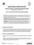
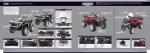
VENTILATEURS
C.VEC
FAN CASINGS
Manuel d’instructions
Instructions manual
■ RECOMMANDATIONS
À LA MISE EN ŒUVRE
■ RECOMMENDATIONS
FOR INSTALLATION
1. Pour éviter les vibrations, nous conseillons :
- un socle anti-vibratile,
- des manchettes souples d’aspiration et
de refoulement.
1. To avoid any vibrations, we recommend using :
- an anti-vibration base,
- flexible suction and discharge sleeves.
2. To operate the fans, we recommend
using :
- gloves to avoid any injuries through the
sharp steel sheet edges of the casing,
- appropriate handling equipment to
avoid endangering staff or damaging the
products.
2. Pour manipuler les ventilateurs, nous
conseillons :
- d’utiliser des gants pour éviter toutes
blessures au contact des tôles d’acier
constituant le caisson,
- d’utiliser des appareils de manutention
adéquats, afin de ne pas mettre en danger le personnel, ou endommager les
produits.
3. The fan must be connected to its air
ducting before starting-up.
The installation must be executed so that
no contact with moving parts is possible.
The installation must be executed by a
qualified person.
Provide clearance on the side opposite
the access for maintenance of internal
devices.
3. Le ventilateur devra être raccordé à
son réseau aéraulique avant la mise en
route.
L’installation doit être réalisée de façon à
ce que le contact avec les parties en mouvement soit impossible.
L’installation doit être réalisée par du personnel qualifié.
Prévoir un espace libre côté face d’accès
pour l’entretien des organes intérieurs.
4. Before starting-up, check that no foreign object has been left inside the casing
or in the fan to avoid this being ejected
under the effect of the pressure or the fan
impeller blocking.
4. Vérifier avant la mise en route qu’aucun objet parasite ne se trouve dans le
caisson ou dans le ventilateur pour éviter
que celui-ci ne soit éjecté sous l’effet de la
pression ou ne bloque la roue du ventilateur.
2
■ MISES EN GARDE
■ WARNINGS
• Ne pas faire fonctionner les ventilateurs
caisson ouvert.
• Do not operate the fans with the casing
open.
• Ne pas essayer de passer un outil au
travers du refoulement pendant le fonctionnement d’un ventilateur.
• Do not try to pass a tool through the
discharge when the fan is operating.
• The fans have not been designed for use
with air containing chlorine gas.
• Ces ventilateurs ne sont pas prévus
pour extraire de l’air contenant des
vapeurs de chlore.
• The fans are not designed to extract air
containing explosive gas mixtures and
must not be used in an explosive atmosphere or be connected to chimney
stacks.
• Ces ventilateurs ne sont pas prévus
pour extraire de l’air contenant des
vapeurs explosives et ne doivent pas
être utilisés dans une atmosphère
explosive ou raccordés à des cheminées.
• These fans are not designed for smoke
extraction.
• Ces ventilateurs ne sont pas prévus
pour faire du désenfumage.
If you wish to use these fans to extract air
containing special fumes, consult us.
Si vous voulez utiliser ces ventilateurs
pour de l’extraction d’air contenant des
vapeurs particulières, nous consulter.
CAUTION :
DISCONNECT THE ELECTRICITY SUPPLY
PRIOR TO ATTEMPTING ANY REPAIRS OR
SERVICING AND MAKE SURE THAT IT
CANNOT ACCIDENTALLY RE-START
DURING THE REPAIRS OR SERVICING.
NEVER ATTEMPT ANY REPAIRS OR SERVICING UNTIL THE FANS HAVE COMPLETELY STOPPED.
IMPORTANT :
COUPER L’ALIMENTATION ÉLECTRIQUE
AVANT TOUTE INTERVENTION SUR UN
VENTILATEUR ET S’ASSURER QU’ELLE NE
PEUT ÊTRE REMISE ACCIDENTELLEMENT PENDANT L’INTERVENTION.
NE PAS INTERVENIR TANT QUE LE VENTILATEUR N’EST PAS COMPLÈTEMENT
ARRÊTÉ.
3
■ RACCORDEMENT
ÉLECTRIQUE
■ SCHÉMAS ÉLECTRIQUES
RACCORDEMENT VENTILATEUR 1 ALLURE
~
vert/jaune
1. La tension d’alimentation est de
230 V~.
M
noir
blanc
thermo-contact
2. Le raccordement électrique se fera
selon les règles de la norme NF C 15-100.
En particulier :
- Le moteur doit être protégé dans l’installation fixe par un dispositif omnipolaire ayant une distance d’ouverture de
3 mm par contact.
- Les câbles d’alimentation doivent avoir
une section au moins égale à 1 mm2 par
conducteur.
- Les câbles d’alimentation ne doivent pas
être plus légers que du H05 VV-F (en
intérieur) ou U1000 R2V (en extérieur).
rouge ou orange
rouge ou orange
RACCORDEMENT VENTILATEUR 2 ALLURES
vert / jaune
rouge / GV
blanc / commun
rouge ou orange
thermocontact
~
3. Nous conseillons également l’emploi
d’un disjoncteur magnéto-thermique.
0,6 à 1 A - code 56.109 pour C.VEC 750.
1,6 à 2,5 A - code 57.052 pour C.VEC 1500.
2,5 à 4 A - code 57.054 pour C.VEC 2500.
(Pour les ventilateurs 1 allure).
M
noir / PV
rouge ou orange
CABLAGE DU THERMO-CONTACT
signalisation
ou
IMPORTANT :
Ne pas oublier de raccorder la terre sur
la vis prévue à cet effet à l’endroit signalé par le symbole .
commun
RACCORDEMENT PRESSOSTAT
Pressostat
alimentation
4. Les moteurs possèdent une sonde thermique à fils sortis (fils rouges ou oranges)
permettant la signalisation d’un défaut.
IMPORTANT : en utilisation “Collectif”, si
cette sonde est raccordée, celle-ci doit être
utilisée uniquement comme signalisation
et ne doit en aucun cas être utilisée pour
couper l’alimentation du moteur sous
peine de perdre le classement Catégorie 4.
R
4
bleu
bleu
marron
MA
noir
AR
R
marron
noir
: relais pouvant être piloté par le pressostat.
Pouvoir de coupure du pressostat sous 250 V
- Résistif : 5 A maxi
- Inductif : 3 A maxi.
■ ELECTRICAL CONNECTION
■ WIRING DIAGRAMS
1. The supply voltage is 230 VAC.
FAN CONNECTION 1 SPEED
~
green/yellow
2. The electrical connections will be
made as per the rules of French standard
NF C 15-100.
In particular :
- The motor must be protected in a fixed
installation using an omnipolar device
with an opening gap of 3 mm per
contact.
- Supply cables must have less or equal to
1 mm2 section per conductor.
- Supply cables must not be lighter than
H05 VV-F (inside) or U1000 R2V (outside).
M
black
thermal-switch
white
red or orange
red or orange
FAN CONNECTION 2 SPEEDS
green / yellow
red / high
3. We also recommend the use of a
magneto-thermic circuit breaker.
0,6 to 1 A - code 56.109 for C.VEC 750.
1,6 to 2,5 A - code 57.052 for C.VEC 1500.
2,5 to 4 A - code 57.054 for C.VEC 2500.
(For fans 1 speed).
white / common
M
black / low
thermalswitch
red or orange
red or orange
~
CABLING OF THERMO-CONTACT
signaling
or
CAUTION :
Do not forget to connect the earth to the
screw terminal provided to this effect at
the position indicated by the earth symbol .
common
PRESSURE SWITCH CONNECTION
4. Motors are fitted with temperature sensors with outgoing wires (red or orange)
to trip a defect signal.
Pressure switch
blue
supply
blue
IMPORTANT : when used in a collective
installation, if this probe is connected, it
must be used only as an indication and
must in no case be used to cut off the supply of the motor. Otherwise the installation would lose its category 4 classification.
R
5
brown
ON
black
OFF
R
brown
black
: relay which can be operated by the pressure
switch.
Pressure switch break power below 250 V
- Resistive : max. 5 A
- Inductive : max. 3 A.
■ RÉGLAGE DÉBIT-PRESSION
■ FLOW-PRESSURE SETTING
Le C.VEC possède un volet de réglage permettant d’ajuster facilement la courbe
débit-pression du motoventilateur. Pour
le réglage, se reporter aux instructions
figurant sur le dessus de l’appareil.
The C.VEC has a control flap so that the
flow-pressure curve of the motor-driven
fan can be easily adjusted. Refer to the
instructions on the top of the equipment
for this setting.
■ PIÈCES DÉTACHÉES
■ SPARE PARTS
En cas de commandes de pièces détachées, relever les références exactes de
l’appareil sur la plaque signalétique et se
référer au tarif Aldes si nécessaire.
When ordering spare parts, note the
exact references of the equipment on its
identification plate and refer to the Aldes
price list if necessary.
■ ENTRETIEN ANNUEL
■ ANNUAL MAINTENANCE
• Les portes latérales du caisson se
démontent facilement à l’aide d’un
outil.
• Dépoussiérer les aubes du ventilateur
ainsi que les organes intérieurs, aussi
souvent que nécessaire et au minimum
une fois par an, afin d’éviter un déséquilibrage et l’usure des roulements.
• Ne pas utiliser de système à haute pression ou à vapeur pour le nettoyage du
ventilateur et du moteur.
• Vérifier la bonne fixation du moto-ventilateur.
• Vérifier qu’il n’existe pas de bruits anormaux.
• The side doors of the casing can be
easily removed using a tool.
• Dedust the fan blades and the inside
devices as often as necessary and at
least once every year in order to avoid
imbalance and wear on bearings.
• Do not use a high pressure or steam
system to clean the fan or the motor.
• Check the motor-driven fan unit is well
secured.
• Check there are no unusual noises.
6
DÉCLARATION CE DE CONFORMITÉ
CE DECLARATION OF CONFORMITY
Type de matériel
Type of product
Ventilateur en caisson
C.VEC
est développé, conçu et fabriqué conformément aux Directives et Normes citées ci-après
is developped, designed and manufactured in accordance with the following Directives and Standards
Directive Machine / MD
89/392/CEE
EN 292
EN 294
EN 414
Directive CEM / EMC
89/336/CEE
EN 55014
EN 55104
Directive Basse Tension / LVD
73/23/CEE
EN 60335
Le dossier technique étant disponible.
The technical file being available.
La notice d’instruction précise en particulier les règles d’installation et d’utilisation du matériel.
The instruction leaflet gives details on the rules for installation and use of the equipment.
Si le matériel doit être incorporé à une installation, la conformité de l’ensemble doit être réalisée et
déclarée par l’incorporateur final.
If the equipment is forseen to be incorporated, the compliance of the final assembly shall be declared and
is responsability of the incorporator.
A Vénissieux, le 15.04.97
At
Le Directeur Industriel
Industrial Manager
Mr. BROUILLER
7
VENTILATEURS
C.VEC
● ALDES BORDEAUX : Tél.05 56 34 28 79 - Télécopie : 05 56 34 34 25 ● ALDES DIJON : Tél.03 80 52 38 74 - Télécopie : 03 80 52 35 85
● ALDES GRENOBLE : Tél.04 76 53 07 07 - Télécopie : 04 76 53 07 06 ● ALDES LILLE : Tél.03 20 22 40 42 - Télécopie : 03 20 22 28 79
● ALDES LYON : Tél.04 78 78 39 39 - Télécopie : 04 78 78 39 40 ● ALDES MARSEILLE : Tél.04 42 32 03 33 - Télécopie : 04 42 32 01 91
● ALDES MONTPELLIER : Tél.04 67 42 16 16 - Télécopie : 04 67 69 03 65 ● ALDES NANCY : Tél.03 83 25 79 79 - Télécopie : 03 83 25 78 81
● ALDES NANTES : Tél.02 40 92 15 10 - Télécopie : 02 40 92 14 27 ● ALDES NICE : Tél.04 93 08 86 66 - Télécopie : 04 93 08 86 56
● ALDES PARIS ANTONY : Tél.01 46 11 45 00 - Télécopie : 01 46 66 49 26 ● ALDES PARIS LA COURNEUVE : Tél.01 43 11 10 10 - Télécopie : 01 48 36 14 72
● ALDES PARIS RUEIL : Tél.01 41 39 94 70 - Télécopie : 01 47 08 30 14 ● ALDES PARIS VITRY : Tél.01 47 18 10 01 - Télécopie : 01 46 82 93 59
● ALDES POITIERS : Tél.05 49 62 87 10 - Télécopie : 05 49 62 89 99 ● ALDES RENNES : Tél.02 99 14 51 60 - Télécopie : 02 99 14 57 92
● ALDES ROUEN : Tél.02 35 71 30 38 - Télécopie : 02 35 89 68 81 ● ALDES STRASBOURG : Tél.03 88 60 13 10 - Télécopie : 03 88 61 54 10
● ALDES TOULOUSE : Tél.05 34 60 29 70 - Télécopie : 05 61 44 26 83 ● ALDES TOURS : Tél.02 47 63 15 15 - Télécopie : 02 47 32 08 23
● SERVICE INTERNATIONAL - Tél.04 78 77 15 15
ALDES se réserve le droit d’apporter toutes modifications liées à l’évolution de la technique.
57904B / VC 512 / RCS 956 506 828 - Imprimé en France
FAN CASINGS