1
170.IU0.LXE.A00
H
H
H
H
5/01
USER MANUAL
MANUEL DE SERVICE
BENUTZERHANDBUCH
ISTRUZIONI D'USO
Ixe-0-A00.p65
1
LDE
LME
14/05/01, 9.32
A. 2
Ixe-0-A00.p65
2
14/05/01, 9.32
INDEX
A.
1.
2.
3.
4.
5.
6.
7.
8.
B.
INDEX
GB
OUTLINE AND CUT OUT DIMENSIONS ...... A.4
MOUNTING .................................................... 1
ELECTRICAL CONNECTIONS ........................ 2
PRELIMINARY HARDWARE
SETTINGS ...................................................... 5
CONFIGURATION .......................................... 6
4.1 Pushbutton function ............................. 6
4.2 Possible protection of the parameters . 6
4.3 Access to the configuration
procedure .............................................. 6
4.4 Configuration parameters ..................... 7
OPERATIVE MODE ..................................... 11
5.1 Preliminary comments ......................... 11
5.2 Indicators ............................................ 11
5.3 Function of the pushbuttons .............. 12
5.4 Manual reset of the alarm ................... 12
5.5 SMART algorithm ................................ 12
5.6 Inhibition of the out signal .................. 13
5.7 Direct modification of the set point .... 13
5.8 Displaying the set point set
(model LDE) ......................................... 13
5.9 Lamp test ............................................ 13
5.10 Operative parameters ......................... 14
ERROR MESSAGES .................................... 16
6.1 Measurement anomaly signal ............ 16
6.2 Error messages .................................. 17
6.3 List of possible errors ........................ 17
TECHNICAL CHARACTERISTICS ................ 18
7.1 Technical specifications ..................... 18
7.2 Inputs .................................................. 18
7.3 Control actions .................................... 19
7.4 Outs .................................................... 19
7.5 CPI - Configuration Port Interface ...... 20
MAINTENANCE ............................................ 20
DEFAULT PARAMETERS ............................ B.1
A.
1.
2.
3.
4.
5.
6.
7.
8.
B.
D
ABMESSUNGEN UND BOHRUNGEN .......... A.4
MONTAGE ...................................................... 1
ELEKTRISCHE ANSCHLÜSSE ....................... 2
VORBEREITENDE HARDWAREEINSTELLUNGEN .......................................... 5
KONFIGURIERUNG ....................................... 6
4.1 Funktionsweise der Tasten ................... 6
4.2 Eventueller Schutz der Parameter ....... 6
4.3 Zugang zum
Konfigurierungsverfahren ..................... 6
4.4 Konfigurierungsparameter ..................... 7
BETRIEBSWEISE ........................................ 11
5.1 Vorbereitende Maßnahmen ................. 11
5.2 Anzeigen ............................................. 11
5.3 Funktionsweise der Tasten ................. 12
5.4 Manuelle Alarmrückstellung ................ 12
5.5 SMART-Algorithmus ............................ 12
5.6 Sperrung des Ausgangssignals .......... 13
5.7 Direkte Änderung des Sollwerts ......... 13
5.8 Anzeige des eingestellten Sollwerts
(Modell LDE) ....................................... 13
5.9 Lamptest ............................................. 13
5.10 Betriebsparameter ............................... 14
FEHLERMELDUNGEN .................................. 16
6.1 Anzeige von Anomalien der Messung 16
6.2 Fehlermeldungen ................................. 17
6.3 Verzeichnis der möglichen Fehler ...... 17
TECHNISCHE EIGENSCHAFTEN ................. 18
7.1 Technische Spezifikationen ................ 18
7.2 Eingänge ............................................. 18
7.3 Steuerungen ........................................ 19
7.4 Ausgänge ............................................ 19
7.5 CPI - Configuration Port Interface ...... 20
WARTUNG .................................................... 20
DEFAULTPARAMETER ............................... B.1
A. 3
Ixe-0-A00.p65
3
14/05/01, 9.32
INDEX
A.
1.
2.
3.
4.
5.
6.
7.
8.
B.
INDICE
F
DIMENSIONS ET PERCAGE ....................... A.4
MONTAGE ...................................................... 1
RACCORDEMENTS ELECTRIQUES .............. 2
MISE AU POINT PRELIMINAIRE DU
MATERIEL INFORMATIQUE ...................... 5
CONFIGURATION .......................................... 6
4.1 Configuration des touches ................... 6
4.2 Protection éventuelle des paramètres . 6
4.3 Accès à la procédure de configuration 6
4.4 Paramètres de configuration ................ 7
DIALOGUE UTILISATEUR ........................... 11
5.1 Préliminaires ........................................ 11
5.2 Indicateurs .......................................... 11
5.3 Configuration des touches ................. 12
5.4 Acquit manuel de l'alarme ................... 12
5.5 Algorithme SMART .............................. 12
5.6 Invalidation du signal de sortie .......... 13
5.7 Modification directe du point de
consigne .............................................. 13
5.8 Visualisation du point de consigne
programmé (modèle LDE) .................... 13
5.9 Lamp test ............................................ 13
5.10 Paramètres de fonctionnement ........... 14
MESSAGES D'ERREUR ............................... 16
6.1 Indication d'anomalie de la mesure .... 16
6.2 Messages d'erreur .............................. 17
6.3 Liste des erreurs éventuelles ............. 17
CARACTERISTIQUES TECHNIQUES .......... 18
7.1 Spécifications techniques .................. 18
7.2 Entrées ............................................... 18
7.3 Actions de contrôles ........................... 19
7.4 Sorties ................................................. 19
7.5 CPI - Configuration Port Interface ...... 20
ENTRETIEN .................................................. 20
PARAMETRES PAR DEFAUT ...................... B.1
A.
1.
2.
3.
4.
5.
6.
7.
8.
B.
I
DIMENSIONI E FORATURA ........................ A.4
MONTAGGIO ................................................. 1
COLLEGAMENTI ELETTRICI ......................... 2
IMPOSTAZIONI HARDWARE
PRELIMINARI ................................................. 5
CONFIGURAZIONE ........................................ 6
4.1 Operatività dei pulsanti ........................ 6
4.2 Eventuale protezione dei parametri ...... 6
4.3 Accesso alla procedura di
configurazione ...................................... 6
4.4 Parametri di configurazione .................. 7
MODO OPERATIVO ..................................... 11
5.1 Preliminari ............................................ 11
5.2 Indicatori ............................................. 11
5.3 Operatività dei pulsanti ...................... 12
5.4 Riarmo manuale dell'allarme ................ 12
5.5 Algoritmo SMART ................................ 12
5.6 Inibizione del segnale di uscita .......... 13
5.7 Modifica diretta del set point .............. 13
5.8 Visualizzazione del set point
impostato (modello LDE) ..................... 13
5.9 Lamp test ............................................ 13
5.10 Parametri operativi .............................. 14
MESSAGGI DI ERRORE .............................. 16
6.1 Segnalazione anomalia della misura .. 16
6.2 Messaggi di errore .............................. 17
6.3 Lista degli errori possibili .................... 17
CARATTERISTICHE TECNICHE ................... 18
7.1 Specifiche tecniche ............................ 18
7.2 Ingressi ............................................... 18
7.3 Azioni di controllo ............................... 19
7.4 Uscite .................................................. 19
7.5 CPI - Configuration Port Interface ...... 20
MANUTENZIONE .......................................... 20
DEFAULT PARAMETERS ............................ B.1
A. 4
Ixe-0-A00.p65
4
14/05/01, 9.32
A.
OUTLINE AND CUT OUT DIMENSIONS
DIMENSIONS ET PERÇAGE
ABMESSUNGEN UND BOHRUNGEN
DIMENSIONI E FORATURA
LDE
LME
A. 5
Ixe-0-A00.p65
5
14/05/01, 9.32
A. 6
Ixe-0-A00.p65
6
14/05/01, 9.32
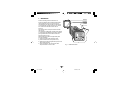
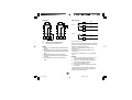
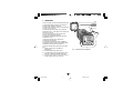
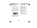
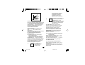
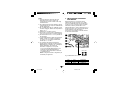
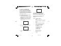
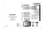
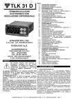
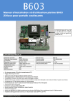
1. MOUNTING
screws
bracket
gasket
panel
Select a mounting location where there is
minimum vibration and the ambient temperature
ranges between 0 and 50°C (32 and 122°F).
The instrument can be mounted on a panel up to
15 mm thick with a square cutout of 45 x 45 mm.
For outline and cutout dimensions refer to
page A.4.
The surface texture of the panel must be better
than 6.3 µm.
The instrument is fitted with a rubber panel gasket.
To assure IP65 and NEMA 4 protection, insert the
panel gasket between the instrument and the
panel as shown in Fig. 1.
While holding the instrument against the panel
proceed as follows:
1) insert the gasket in the instrument case;
2) insert the instrument in the panel cutout;
3) pushing the instrument against the panel, insert
the mounting bracket;
4) with a screwdriver, turn the screws with a
torque between 0.3 and 0.4 Nm.
GB
lxe-1-0A.p65
1
Fig. 1 PANEL MOUTING
1
27/04/01, 9.24
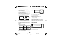
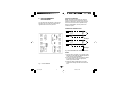
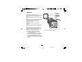
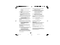
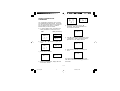
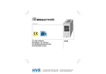
MEASURING INPUTS
NOTE: Any external components (like zener
barriers etc.) connected between sensor and input
terminals may cause errors in measurement due
to excessive and/or not balanced line resistance
or possible leakage currents.
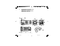
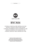
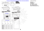
2. ELECTRICAL CONNECTIONS
Connections are to be made with the instrument
housing installed in its proper location.
TC INPUT
+ 9
_ 10
Shield
+ 9
_ 10
Shield
Fig. 3 THERMOCOUPLE CONNECTION
NOTES:
1) Do not run input wires together with power
line cables.
2) For TC wiring use proper compensating cable
preferably shielded.
3) When a shielded cable is used, it should be
connected at one point only.
Fig. 2 REAR TERMINAL BLOCK
GB
lxe-1-0A.p65
2
2
27/04/01, 9.24
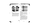
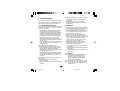
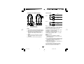
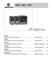
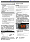
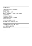
RTD INPUT
RELAY OUTS
RTD
3
RTD
OUT 1
2
1
OUT 2
8
9
10
8
9
6
10
7
NC
C
NO
C
NO
Fig. 5 RELAY OUTS
Fig. 4 RESISTANCE TEMPERATURE
DETECTOR CONNECTION
The OUT 1 NO contact and the OUT 2 contact are
protected by varistors against inductive load with
inductive component up to 0.5 A.
The OUT 1 contact rating is 3A/250V AC on
resistive load.
The OUT 2 contact rating is 2A/250V AC on
resistive load.
The number of operations is 1 x 10⁵ at specified
rating.
NOTES:
1) Do not run input wires together with power line
cables.
2) Pay attention to the line resistance; a resistance
higher than 20 Ω/wire may cause measurement
errors.
3) When shielded cable is used, it should be
grounded at one side only to avoid ground loop
currents.
4) The impedence of the 3 wires must be the
same.
NOTES:
1) To avoid electric shock, connect the power
line at the end of the wiring procedure.
2) For power connections use No 16 AWG or
larger wires rated for at least 75°C.
3) Use copper conductors only.
4) Do not run input wires together with power
line cables.
The following recommendations avoid serious
problems which may occur it when using relay
output to drive inductive loads.
GB
lxe-1-0A.p65
3
3
27/04/01, 9.24
VOLTAGE OUTS FOR SSR DRIVE
INDUCTIVE LOADS
+
High voltage transients may occur when
switching inductive loads.
These transients may introduce disturbances
through the internal contacts which can affect the
performance of the instrument.
The internal protection (varistors) assures correct
protection up to 0.5 A of inductive component but
the OUT 1 NC contact is not protected.
The same problem may occur when a switch is
used in series with the internal contacts.
1
SOLID STATE
RELAY
Fig. 7
POWER
LINE
NOTE: This out is NOT isolated.
A double or reinforced Isolation between instrument
output and power supply must be assured by the
external solid state relay.
Fig. 6 EXTERNAL SWITCH IN SERIES WITH
THE INTERNAL CONTACT
In these cases an additional RC network should
be installed across the external contact as shown
in Fig. 6
The value of the capacitor (C) and resistor (R) are
shown in the following table.
C
(mF)
SSR DRIVE OUT WIRING
It is a time proportioning out.
Logic level 0: Vout < 0.5 V DC.
Logic level 1: Maximum current = 20 mA.
- 14 V + 20 % @ 20 mA
- 24 V + 20 % @ 1 mA.
LOAD
LOAD
(mA)
R
(W)
P.
(W)
OPERATING
VOLTAGE
<40 mA 0.047 100
<150 mA
0.1
22
<0.5 A
0.33 47
1/2
2
2
260 V AC
260 V AC
260 V AC
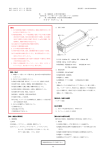
POWER LINE WIRING
N
5
4
Power Line
100 V to 240 V AC (50/60Hz)
or 24 V AC/DC
R (S,T)
Fig. 8 POWER LINE WIRING
In every case the cable connected to the relay
outs must be routed as far away as possible from
input or communication cables.
GB
lxe-1-0A.p65
4
+
_
_
4
27/04/01, 9.24
N
R
OUT 1
R (S,T)
C
2
NOTES:
1) Before connecting the instrument to the supply,
make sure that the line voltage corresponds to
that indicated on the rating plate.
2) To avoid electric shock, connect the power line at
the end of the wiring procedure.
3) For supply connections use No 16 AWG or larger
wires rated for at least 75°C.
4) Use copper conductors only.
5) Do not run input wires together with power line
cables.
6) For 24 V AC/DC the polarity does not matter.
7) The power supply input has NO fuse protection.
Please, provide a T type 1A, 250 V fuse externally.
8) The safety regulations for equipment
permanently connected to the mains require
that there is a switch or circuit breaker in the
building electrical system and that this:
- is near the device and can easily be reached by
the operator;
- is marked as the device ON/OFF device.
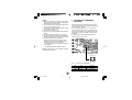
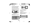
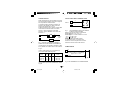
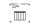
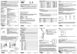
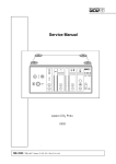
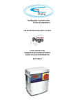
3. PRELIMINARY HARDWARE
SETTINGS
These instruments can detect the opening of the
input circuit (TC or RTD). This failure is displayed
as an overrange condition.
For the thermocouples only one can select, by
means of jumpers SH1 and CH1 indicated in Fig.
9, the type of indication to be obtained when the
thermocouple is open (see table at the bottom of
the page).
To gain access to the jumpers the instrument
must be taken out of its case.
NOTE: A single switch or circuit-breaker can drive
more than one instrument.
SH1 CH1
Fig. 9 SH1 and CH1 JUMPERS
GB
lxe-1-0A.p65
5
SH1
CH1
Indication
open
close
close
open
overrange (standard)
underrange
5
27/04/01, 9.24
If the modification of the parameters has been
enabled, the passage in configuration is free.
If not it will be allowed by entering, when
requested, the numerical value programmed in
P11, or code 408.
P11 = 500/999 As for the previous point, with the
difference that AL (alarm threshold) can be
modified as well as SP.
4. CONFIGURATION
4.1 PUSHBUTTON FUNCTION
FUNC
This saves the new value of the
selected parameter and goes to the
next parameter (increasing order).
SMT
This scrolls back the parameters
without saving the new value.
I
This increases the value of the
selected parameter.
J
This decreases the value of the
selected parameter.
In the two previous cases, with P14 = On the
parameters set as not modifiable can however be
displayed. With P14 = OFF they are not.
4.3 ACCESS TO THE CONFIGURATION
PROCEDURE
To access the configuration, press SMT and
FUNC simultaneously (press first SMT and
immediately afterwards FUNC) keeping both the
pushbuttons pressed for three seconds.
In the model LME the lower display will show Cnf,
the upper OFF. In model LDE OFF and CnF will
appear alternatively.
Press I or J within 10 seconds to set ON, then
confirm with FUNC.
If the device is in the protected condition (see
previous section), the lower display (LME) shows
Cnf, the upper a dashed line (instead of OFF). In
model LDE the two wordings appear alternately.
By means I or J enter the value entered in P11, or
value 408. Press FUNC to confirm.
The instrument is now in configuration mode, and
the display shows Cnf steadily for both models.
Via FUNC we advance to the first parameters.
4.2 POSSIBLE PROTECTION OF THE
PARAMETERS
Access to the configuration, and the display and
modification of the operative parameters, can be
protected by a secret code. The code is entered in
configuration, by means of parameters P11 and
P14.
P11 = 0 All the operative parameters can be
displayed and modified. Access to the
configuration is free.
P11 = 1 and P14 = On All the operative
parameters can be displayed but not modified,
apart from SP (Set Point). Access to the
configuration is only possible by entering code 408
when requested.
P11 = 1 and P14 = OFF No operative parameter
can be displayed and modified, apart from SP.
Access to the configuration is only possible by
entering code 408 when requested.
P11 = 2/499 In this case the value programmed in
P11 represents a numerical key which can be
used to protect access to the configuration and, in
operative mode, the modification of the
parameters (SP can always be modified).
To set P11 see section 4.4.
GB
lxe-1-0A.p65
6
In configuration, the lower display shows the
code of the parameter (P1-P21), the upper the
numerical value or the selection code. In the
model LDE, the display shows the parameter
code and the numerical value alternatively.
6
27/04/01, 9.24
To alter the value set press I or J and confirm
with FUNC.
The parameter for loading the default parameters
is shown in section B at the end of the manual.
P2 = Initial range value
Initial range value for input from thermocouple/
Resistance Temperature Detector.
4.4 CONFIGURATION PARAMETERS
P3 = Full range value
Full range value for input from thermocouple/
Resistance Temperature Detector.
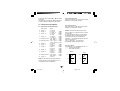
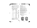
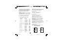
P1 - Type of input and standard range
Type of input
0 TC type L
1 TC type J
2 TC type K
3 TC type N
4 RTD type Pt 100
5 RTD type Pt 100
6 TC type T
8 TC type L
9 TC type J
10 TC type K
11 TC type N
12 RTD type Pt 100
13 TC type T
Range
0 / +900 °C
0 / +999 °C
0 / +1000 °C
0 / +999 °C
0 / +1370
0 / +999 °C
0 / +1400 °C
-199 / +800 °C
-200 / +800 °C
-19.9 / +99.9 °C
-199.9 / +400.0 °C
0 / +400 °C
0 / 999 °F
0 / 1652 °F
0 / 999 °F
0 / 1832 °F
0 / 999 °F
0 / 2498 °F
0 / 999 °F
0 / 2552 °F
-199 / 999 °F
-328 / 1472 °F
0 / 752 °F
NOTES: The minimum input span (P3 - P2) is
300°C or 600°F for TC input and 100°C or 200°F
for RTD input.
On every parameter change P1, P2 is forced to
the minimum value, P3 to the maximum value.
If the value of P2 and/or P3 is modified the
parameter rL is automatically aligned to the new
value (of P2 and/or P3).
If P5 = 1, parameter AL is checked and
automatically aligned if it is out of range.
(LME)
(LDE)
(LME)
(LDE)
(LME)
(LDE)
(LME)
(LDE)
(LME)
(LDE)
(LME)
(LDE)
(LME)
(LDE)
(LME)
(LDE)
(LME)
(LDE)
(LME)
(LDE)
P4 = Out 1 action
This parameter is not modifiable when P5 = 5
rEU = reverse action (Heating)
dir = direct action (Cooling)
Reverse
Input
Out
t
Out
t
GB
7
Input
t
NOTE: On the instrument front panel two leds
indicate the setting of the temperature in °C or
°F, depending on the configuration.
lxe-1-0A.p65
Direct
7
27/04/01, 9.24
t
P5 = Function of Out 2
0 = Not provided
1 = Process alarm
2 = Band alarm
3 = Deviation alarm
4 = Instrument failure alarm
5 = Cooling out
NOTE: Modifying parameter P6 automatically
updates the values of the cooling cycle time
and the cooling gain.
P6
Air
OIL
H2O
NOTE: When P5 = 1, 2, 3, 4: if parameter OLH is
less than 0, it is set to 100; if parameter IP is
less than 0 it is set to 30;
when P5 = 0, 1, 2, 3: parameter AL is checked and
if it is out of range it is set to the lowest value.
When P5 = 5: parameter P4 automatically
assumes the value “rEU”; parameter P16 is
checked and if it is out of range it is set to the
lowest value; if parameter Pb is not 0 and is lower
than 1.5, it is set to 1.5.
C2
10 (s)
4 (s)
2 (s)
P7 = Alarm action
Only available when P5 is different from 0 or 5.
rEU = reverse (relay de-energized in alarm
condition)
dir = direct (relay energized in alarm condition)
P8 = Stand-by of the alarm
Only available when P5 is 1, 2 or 3.
OFF = stand-by disabled
ON = stand-by enabled
P6 = Configuration Out 2
P6 is skipped when P5 = 0.
If P5 = 1, 3 or 4;
H.A. = High alarm with automatic reset
L.A. = Low alarm with automatic reset
H.L. = High alarm with manual reset
L . L . = Low alarm with manual reset
When P5 = 4, the "high" or "low" selection has no
effect.
NOTE: The alarm stand-by function disables the
alarm indication at instrument start up and after
a set point modification until the process
variable reaches the alarm threshold.
P9 = OFFSET applied to the measured value
This OFFSET is applied along the whole span.
When P1= 5
P9 is programmable from -19.9
to 19.9°C.
When P1 ≠ 5
P9 is programmable from -199
to 199°C or °F.
If P5 = 2:
H . A . = out of band with automatic reset
L.A. = in band with automatic reset
H.L. = out of band with manual reset
L.L. = in band with manual reset
When P5 = 5 this parameter selects the cooling
medium.
AIr = air
OIL = oil
H2O = water
GB
lxe-1-0A.p65
8
RC
1
0.8
0.4
8
27/04/01, 9.24
Readout
P9
To make the device
“Locked” enter a number
different from the “secret
code”.
B)
The key is enabled: no
ON
parameter can be modified
apart from SP.
nnn
To “Unlock” the device,
insert the “secret code”.
500 to 999: Selecting a secret code between
these two numbers, everything will occur as
explained above except that when the device is
“Locked” the parameters that can be modified are
the set point and the alarm threshold.
Real curve
Adjusted
curve
Input
P10 = Threshold of the “Soft Start” function
The “Soft start” function limits the maximum out
power (see OLH operative parameter) for a
programmable time (see tOL operative parameter)
at the instrument start up when the measured
value is lower then the programmed threshold.
P10 is the threshold value, in engineering units.
If tOL = InF, P10 value is not considered.
NOTE: The instrument shows on the display the
value 2 for any value of P11 between 2 and 999.
P12 = Out maximum rate of rise
This parameter is only available if Pb is not 0.
Programmable from 1 to 25% of the out signal per
second.
Over 25%/s the instrument displays “InF” to
indicate the exclusion of the limitation.
Every time parameter P1 is changed it is forced
to the minimum value.
P11 = Safety lock
0 = device unlocked. All the parameters can be
modified
1 = device locked. None of the parameters can be
modified except the SP.
2 to 499 = SP can be always modified.
Select the secret code (to be remembered) and
during the “operative mode” and scrolling the
“software key” parameter, the display will show
one of the following figures:
A)
OFF
nnn
P14 = Protected parameters display
This parameter is only available if P11 is not 0.
This parameter enables/disables the display of the
protected parameter during "operative mode".
The device is “Unlocked”
and all parameters can be
modified.
GB
lxe-1-0A.p65
P13 = Not used
9
9
27/04/01, 9.24
OFF
= the protected parameters are not
displayed
ON = the protected parameters are displayed
P15 - SMART function enabling/disabling
0 = The SMART function is disabled
1 = SMART function enabling/disabling is
NOT protected by the safety code.
2 = SMART function enabling/disabling is
protected by the safety code.
P16 - Maximum value of the proportional band
automatically settable by the SMART
function
This parameter is available if P15 is not 0. It can
assume the following values:
model LME: between P17 or P18 and 99.9%
model LDE: between P17 or P18 and 100.0%
P17 - Proportional minimum band value
automatically settable by the SMART
function ( one control out only)
This parameter is only displayed if P5 is not 5 or
P15 is not 0.
It may be programmed from 1.0% to the value of
P16.
P18 - Proportional minimum band value
automatically settable by the SMART
function (two control outs, heating/
cooling)
This parameter is only present if P5 is 5 and
P15 is not 0.
This parameter may be programmed from 1.5%
to the value of P16.
P19 = Automatic calculation of "relative
cooling gain"
This parameter is only present if P5 is 5 and P15
is not 0.
OFF = the SMART function does NOT calculates
the "relative cooling gain".
ON = the SMART function calculates the "relative
cooling gain".
P20 = Minimum integral time value calculated
by the SMART function
This parameter is only present if P15 is not 0.
It can assume the following values:
model LME: between 0.1 (1 tenth of a second)
and 2.0 (2 minutes)
model LDE: between 00.01 (1 second) and 2.00
(2 minutes).
P21 = Extension of the anti-reset-wind up
Span: from -30 to +30 % of the proportional band.
NOTE: a positive value increases the high limit of
the anti-reset-wind up (over set point) while a
negative value decreases the low limit of the antireset-wind up (under set point).
The advanced configuration procedure is
completed and the instrument shows "CnF" on the
display.
To quit the configuration, press SMT and FUNC
simultaneously (press first SMT and immediately
afterwards FUNC) keeping both the pushbuttons
pressed for three seconds.
GB 10
lxe-1-0A.p65
10
27/04/01, 9.24
5. OPERATIVE MODE
The display and modification of the operative
parameters can be protected by a secret code.
For more information see section 4.2.
5.1 PRELIMINARY COMMENTS
It is assumed, at this point, that the instrument has
been correctly configured as indicated in
Section 4.
- Model LME displays the value measured on the
upper display: the lower display is normally
used to display the operating set point (below
this condition is defined as “Normal display”).
- Model LDE displays the value measured (below
this condition is defined as “Normal display”) or,
alternatively, the operating set point (in this
case the SP led lights up).
To change from the display of the set point to
that of the value measured, or vice versa, press
pushbutton I.
All the parameters can be displayed sequentially
by pressing the FUNC pushbutton.
- Model LME displays the abbreviated name of
the parameter selected on the lower display, on
the upper display the value set.
- Model LDE displays alternatively the name of
the parameter and its value: during the
modification it displays only the value.
To modify the setting of a parameter proceed as
follows:
1) By means of the FUNC pushbutton select the
parameter to be modified.
2) Using the I and J keys set the value
required.
3) Press the FUNC pushbutton to save the new
value and go to the next parameter.
4) Press SMT to return to the previous
parameter without saving.
NOTES:
1) If, during parameter modification, no
pushbutton is pressed for more than 10
seconds, the instrument automatically reverts
to the “normal display mode” and the new
setting of the last parameter will be lost.
2) In the “normal display”, on pressing
pushbutton I or J and keeping it pressed for
more than two seconds, one can directly
access the set point value, which can be
modified by pressing I or J again (see section
5.7).
3) The instrument does not display all the
possible parameters, but only those which are
in agreement with:
a) The instrument configuration (see section
4).
b) The setting of parameter P14 (see section
4).
c) The setting of the proportional band (see
section 5.5).
5.2 INDICATORS
SMT Flashes when the first part of the SMART
algorithm is active.
Lit when the second part of the SMART
algorithm is active.
OUT1 Lit up when out 1 is ON.
OUT2 Lit up when out 2 is ON.
°C
Lit up if the temperature is displayed in °C.
°F
Lit up if the temperature is displayed in °F.
SP
(LDE only) Lit when the display shows the
operative set point.
GB 11
lxe-1-0A.p65
11
27/04/01, 9.24
5.3 FUNCTION OF THE PUSHBUTTONS
FUNC
Saves the new value of the selected
parameter and goes to the next
parameter (increasing order).
SMT
Enables or disables the SMART
function and scrolls back all the
parameters without saving them.
I
Increases the value of the selected
parameter or (LDE only) displays the
set point value or the measured value.
J
Decreases the value of the selected
parameter.
J + FUNC Enables/disables the "LAMP TEST".
NOTE: The operative parameters must be
modified within 10 seconds. If, during operative
parameter modification, no pushbutton is pressed
during this time, the instrument automatically
reverts to the “normal display mode”. Saving only
the parameter modifications which were followed
by pressing the FUNC pushbutton.
5.4 MANUAL RESET OF THE ALARM
If the alarm has been configured as a latched
alarm, the alarm status persists even after the
alarm condition disappears.
To reset the alarm, press the FUNC pushbutton to
select the parameter “n.rS” (the display will show
“n.rS” and “OFF”. Use the I and J pushbuttons to
select “ON” and press the FUNC pushbutton.
The alarm reset action will only be successful if
the alarm condition has disappeared only.
5.5 SMART ALGORITHM
This function gives best process control.
To enable the SMART function, press the SMT
pushbutton for more than 1.5 s, when the
instrument is in normal display mode. The SMT
LED will be lit continuously or flash according to
the algorithm automatically selected.
When the SMART function is enabled, the
traditional control parameters (PB, TI, TD and rC)
can be displayed but not modified.
When the traditional control (PID) is desired, press
the SMT pushbutton again (for more than 1.5 s) to
turn the "SMART" OFF. The instrument maintains
the actual control parameters setting and allows
parameter modification.
NOTES:
1) During operation of the SMART function, the
relative cooling gain (if controlled by SMART) is
limited within the following ranges:
Cooling medium
Span
Air
0.85 to 1.00
OIL
0.80 to 0.90
H2O
0.30 to 0.60
2) The SMART function uses a derivative time equal
to 1/4 of the integral time.
3) The limits of the proportional band settable by
the SMART function are programmed by
parameters P16, P17 and P18 .
4) The lower limit of the integral time settable by
the SMART function is programmed by
parameter P20 .
5) When ON/OFF control is programmed (Pb=0),
the SMART function is disabled.
6) SMART enabling/disabling can be protected
by the safety lock (see parameter P15).
GB 12
lxe-1-0A.p65
12
27/04/01, 9.24
5.6 INHIBITION OF THE OUT SIGNAL
These products allow to turn the out signal OFF
manually to stop the control.
To turn the out signal OFF, press the I pushbutton
first and then press the FUNC pushbutton.
Keeping them both pressed for more than 3
seconds, the instrument will show “OFF” instead of
the set point value.
The instrument will display “OFF” instead of
indicating the set point; the out signal will switch
OFF and the instrument will work as a simple
indicator.
When the control outs are disabled, the alarms are
also disabled and forced to the no-alarm condition.
The modification of the control parameters is still
enabled.
To return to normal control, press the I pushbutton
first and then press the FUNC pushbutton.
Keeping them both pressed for more than
3 seconds, the instrument returns to normal
display mode.
NOTES :
1) If the out is turned OFF when the SMART
function is performing the first part of the SMT
algorithm (LED SMT flashing), the SMART
function will be aborted and when the
instrument comes back to the normal control,
the SMART function will be disabled.
If the out is turned OFF when the SMART
function was performing the second part of the
SMT algorithm (LED SMT lit), the SMART
function will be stopped and, when the
instrument comes back to the normal control,
the smart function will also be activated.
2) If the instrument is turned OFF with the out
power off function enabled, at the next start up
this function will automatically be enabled
again.
5.7 DIRECT MODIFICATION OF
THE SET POINT
The instrument modifies the set point value without
using the FUNC pushbutton.
When direct access to set point modification is
required, proceed as follow:
1) Press pushbutton Ior Jfor more than
2 seconds; the set point value will be
displayed and it will start to change.
2) Using the Iand J pushbuttons, set the
desired value.
3) When the desired value is reached, DO NOT
press any pushbutton, the new set point will
become operative after 2 seconds after the
pushbuttons were last pressed and the
instrument will return to the “normal display”.
If during this procedure the modification is not to
be saved, press the FUNC pushbutton
immediately (within 2 seconds); the instrument
automatically returns to the normal display without
saving the new set point.
5.8 DISPLAYING THE SET POINT SET
(model LDE)
To display the set point set, press the J
pushbutton. The SP led lights up.
The set point value will appear on the display.
To return to the display of the value measured
press pushbutton J again.
5.9 LAMP TEST
To check the display efficiency, press
pushbuttons J + FUNC. The instrument will turn
ON, with a 50% duty cycle, all the LEDs of the
display (this state is called LAMP TEST).
GB 13
lxe-1-0A.p65
13
27/04/01, 9.24
No time out is applied to the LAMP TEST.
To return to the normal display mode, press
pushbuttons J + FUNC again.
No other keyboard functions are available during
the LAMP TEST.
5.10 OPERATIVE PARAMETERS
The following is a list of all the available control
parameters.
Note that some parameters may not be displayed
depending on the specific instrument
configuration.
Press the FUNC pushbutton. In model LME, the
lower display will display the abbreviated name
while the upper display will display the value of the
parameter selected. In model LDE the display will
show the values alternatively.
The value or state required can be set by means
of pushbuttons I and J.
On pressing pushbutton FUNC, the instrument
saves the new value (or the new state) and goes
to the next parameter.
Param. Description
SP
Set point (in eng. units).
Span: from rL to rH.
n.rS
Manual reset of the alarms.
This parameter is displayed if one alarm
has been programmed with manual
reset.
Set ON and press the FUNC pusbutton
to reset the alarms.
nnn
Software key for parameter protection.
This parameter is skipped if P11 = 0 or
1.
ON = the instrument is in LOCK
condition
AL
HSA
Pb
OFF = the instrument is in UNLOCK
condition.
To switch from LOCK to UNLOCK, set a
value equal to the value of parameter
P11.
To switch from UNLOCK to LOCK, set a
value different from the value of
parameter P11.
Span: 2/999
Alarm threshold (in eng. units).
Parameter AL is only displayed if
P5 = 1, 2 or 3.
Spans:
- From P2 to P3 for process alarm
(P5 = 1)
- From 0 to 500 units for band alarm
(P5 = 2).
- From -199 to 500 units for deviation
alarm (P5 = 3).
Alarm hysteresis (in % of P3 - P2 span).
This parameter is only displayed if the
alarm is configured.
Span: From 0.1% to 10.0% of the input
span or 1 LSD.
Note: If the hysteresis of a band alarm is
larger than the alarm band, the
instrument will use an hysteresis value
equal to the alarm band minus 1 digit.
Proportional band (in % of P3 - P2 span).
Span:
from 1.0% to 99.9% (from 1.0% to 100%
for model LDE) of the input span with
one control out.
From 1.5% to 99.9% (from 1.5% to
100% for model LDE) of the input span
with two control outs.
When the the SMART is ON (see
section 5.5) the value of Pb is limited to
that set in P16-P17 (one control action)
GB 14
lxe-1-0A.p65
14
27/04/01, 9.24
HS
ti
td
IP
C
and to that set on P16-P18 (two control
actions).
When Pb parameter is set to 0, the
instrument performs an ON-OFF
control; the ti, td, IP, C, C2, rC, OLP,
OLH and tOL parameters are skipped
and SMART function is disabled.
Hysteresis for ON/OFF control action (in
% of P3 - P2 span).
This parameter is only available when
Pb = 0.
Span: from 0.1% to 10.0% of the input
span.
Integral time. Is skipped when Pb = 0
(ON/OFF action).
Span model LME: from 0.1 to 20.0 mm.s
(minutes and tens of seconds).
Span model LDE: from 00.01 to
20.00 mm.ss (minutes and seconds)
Above this value the display becomes
dark and the integral action is excluded.
Derivative time. This parameter is
skipped if Pb = 0 (ON/OFF action).
Span model LME: from 0.00 to 9.59
mm.ss (minutes and seconds)
Span model LDE: from 0.00 to 10.00
mm.ss (minutes and seconds).
If 0 is set, the derivative action is
excluded.
Integral pre-load. This parameter is only
available when Pb is not 0.
Span:
- from 0 to 100% for one control action
- from -100 to 100% for two control
actions.
Out 1 cycle time (in seconds).
This parameter is only available when
Pb is not 0.
Span: from 1 to 200 s.
C2
rC
OLP
rL
rH
OLH
tOL
Out 2 cycle time (in seconds).
C2 is only available if Pb is not 0 and
P5 is 5.
Span: from 1 to 200 s.
Relative Cooling gain.
This is skipped if Pb = 0 (ON/OFF action)
or P5 is not 5.
Span: from 0.20 to 1.00
Dead band/Overlap between H/C outs (in
% of the proportional band).
“OLP” is skipped if Pb = 0 (ON/OFF
action) or P5 is not 5.
A negative value shows a dead band
while a positive value shows an overlap.
Span: from -20 to 50%.
Set point low limit (in eng. units).
Span: from min. range value (P2) to rH.
Note: When P2 has been modified, rL will
be realigned to it.
Set point high limit (in eng. units).
Range:from rL to full scale value (P3).
Note: When P3 has been modified,
rH will be automatically realigned to it.
Out maximum limit (in % of the out).
Available only if Pb is not 0.
Span:
- From 0 to 100 when the instrument is
configured with one control out.
- From -100 to 100 when the
instrument is configured for two control
outs.
Duration of the out power limiter (in
minutes).
The tOL is a programmable time in
which the out level is limited to OLH
value.
GB 15
lxe-1-0A.p65
15
27/04/01, 9.24
The count of this time starts when the
instrument is switched on if the
measured variable is less than the
threshold value programmed (P10
parameter of section 4).
This parameter is only present if
parameter PB is not 0.
Span: from 1 to 540 min. Above this limit,
the display shows "Inf" and the limitation
is always entered.
Note: Parameter tOL can be modified
but the new value will only become
operative at the next instrument start
up unless the new value is Inf.
6. ERROR MESSAGES
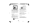
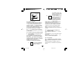
6.1 MEASUREMENT ANOMALY SIGNAL
The instrument display (the upper display for
model LME) shows the OVERRANGE and
UNDERRANGE conditions with the following
indications:
Overrange
Underrange
The example shows the display of model LME.
Model LDE displays 4 digits.
The sensor break can be signalled as:
- for TC/mV input
: OVERRANGE or
UNDERRANGE selected
by a solder jumper
- for RTD input
: OVERRANGE
On RTD input, a special test is provided to signal
OVERRANGE when input resistance is less than
15 ohm (Short circuit sensor detection).
NOTE:
When:
- The instrument is set for one control out only
and an OVERRANGE is detected, the OUT 1
turns OFF (if reverse action) or ON (if direct
action).
- The instrument is set to use two control outs
and an OVERRANGE is detected, OUT 1 turns
OFF and OUT 2 turns ON.
GB 16
lxe-1-0A.p65
16
27/04/01, 9.24
- The instrument is set for one control out only
and an UNDERRANGE is detected, the OUT 1
turns ON (if reverse action) or OFF (if direct
action).
- The instrument is set to use two control outs and
an UNDERRANGE is detected, OUT 1 turns ON
and OUT 2 turns OFF.
For inputs from thermocouple the underrange
indication can be selected as shown in section 7.2
of this manual.
NOTE: When an overrange or an underrange is
detected, the alarms operate as if the
instrument had detected the maximum or
the minimum measurable value
respectively.
To eliminate the out of span condition, proceed as
follows:
1) Check the input signal source and the
connecting line.
2) Make sure that the input signal is in
accordance with the instrument configuration.
Otherwise, modify the input configuration (see
section 4).
3) If no error is detected, send the instrument to
your supplier to be checked.
6.2 ERROR MESSAGES
Diagnostics are made on switching on and during
normal operation.
If the instrument detects an error condition the
display will show:
LME: “Err” in the lower display and the code
which identifies the type of error in the
upper display.
LDE: “E” and the error code.
The complete list of all the possible errors
follows in numerical order.
Some errors automatically reset the instrument:
if the error persists, send the instrument to your
supplier to be checked.
6.3 LIST OF POSSIBLE ERRORS
100
EEPROM writing error.
Consult your supplier.
150
Generic CPU error.
Consult your supplier.
2xx
Error in the configuration parameters.
The two less significant figures indicate
the number of the incorrect parameter
(e.g. 209 Err indicates error of
parameter P9).
Press SMT and FUNC, then set the
parameter correctly.
See section 4.
301
RTD input calibration error.
Contact your supplier.
305
TC input calibration error.
Contact your supplier.
307
RJ input calibration error.
Contact your supplier.
400
Error in the operative parameters.
To deal with the problem, enter the
predefined parameters (“Default
Parameters”, see section B), pressing
pushbuttons J and I at the same time.
Then set the operative parameters.
500
Auto-zero error
Contact your supplier.
502
RJ error
Contact your supplier.
510
Error during calibration.
Contact your supplier.
GB 17
lxe-1-0A.p65
17
27/04/01, 9.24
7. TECHNICAL CHARACTERISTICS
7.1 TECHNICAL SPECIFICATIONS
Case: ABS grey (RAL 7043); self-extinguishing
degree: V-0 according to UL 94.
Front protection - designed and tested for
IP 65(*) and NEMA 4X for indoor locations (when
panel gasket is installed).
(*) Tests were performed in accordance with CEI
70-1 and NEMA 250-1991.
Installation: panel mounting
Rear terminal block:10 screw terminals (screw
M3, for cables from φ 0.25 to φ 2.5 mm2 or from
AWG 22 to AWG 14 ) with connection diagrams
and safety terminal block cover.
Dimensions: according to DIN43700 48 x 48 mm,
depth 105 mm.
Weight: 200 g max.
Power supply:
- 100V to 240V AC 50/60Hz (-15% to + 10% of
the nominal value).
- 24 V AC/DC (+ 10 % of the nominal value).
Power consumption: 9 VA max / 4 W.
Insulation voltage: 2300 V rms according to
EN 61010-1.
Display updating time: 500 ms.
Sampling time: 500 ms.
Resolution: 30000 counts.
Precision: + 0.3% v.f.s. + 1 digit @ 25°C of room
temperature.
Common mode rejection: 120 dB at 50/60 Hz.
Normal mode rejection: 60 dB at 50/60 Hz.
Electromagnetic compatibility and safety requirements: This instrument is marked CE.
It therefore conforms to directives 89/336/EEC
(reference harmonized standard CEI EN-613261:1998 and CEI EN-61326/A1:1999 emission
requirements: residential environment - class B –
for 100/240V AC and industrial environment class A – for 24V AC/DC) and to directives 73/
23/EEC and 93/68/EEC (reference harmonized
standard EN 61010-1).
Installation category: II
Temperature drift: < 200 ppm/°C (RJ excluded)
< 400 ppm/°C for RTD input and input from
thermocouple T.
< 800 ppm/°C for RTD input with 1/10°C
resolution (model LME).
< 500 ppm/°C for RTD input with 1/10°C
resolution (model LDE).
Operating temperature: from 0 to 50°C (from 32
to 122°F).
Storage temperature: -30 to +70°C (-22 to
158°F)
Humidity: from 20 % to 85% RH, non condensing.
Protections:
1) WATCH DOG (hardware/software) for the
automatic restart.
7.2 INPUTS
A) THERMOCOUPLES
Type: L, J, K, N, T programmable from the
keypad.
Line resistance: max. 100 Ω with error <+0.1% of
the input span.
Engineering units: °C or °F programmable.
Reference junction: automatic compensation
from 0 to +50°C (from 32 to122°F).
Reference junction drift : 0.1°C/°C.
Burn-out: Up or down range selectable.
Calibration: according to IEC 584-1 and
DIN 43710 - 1977 (TC L).
GB 18
lxe-1-0A.p65
18
27/04/01, 9.24
TABLE OF STANDARD RANGES
Type of
Measuring spans
TC
In brackets the data of model LDE
L
0 / +999 (1652) °F
0 / +900°C
J
0 / +999 (1832) °F
0 / +999 (1000) °C
K
0 / +999 (2498) °F
0 / +999 (1370) °C
N
0 / +999 (2552) °F
0 / +999 (1400) °C
T
0 / +752 °F
0 / +400 °C
B) RTD (Resistance Temperature Detector)
Type: Pt 100 3 wire connection.
Current: 135 µA.
Line resistance: automatic compensation up to
20 Ω/wire with :
- error <+1% of the input span when P1 = 5.
- not measurable error for the other spans.
Engineering units: °C or °F programmable.
Burn-out: up range.
NOTE: A special test is provided to signal
OVERRANGE when input resistance is less than
15 Ω.
Calibration: according to DIN 43760.
TABLE OF STANDARD RANGES
RTD
type
Measuring span
In brackets the data of model LDE
RTD Pt 100
-199 / +800 °C
(-200 / +800°C)
-199 / +999 °F
(-328 / +1472°F)
RTD Pt 100
-19.9 / +99.9 °C
(-199.9 / +400.0°C)
-
7.3 CONTROL ACTIONS
Control actions: PID or SMART
Proportional band: from 1.0 % (if just one control
out is used) or 1.5 % (if two control outs are used)
to 99.9% (LME) 100% (LDE) of the input span.
On setting Pb = 0 an ON/OFF control is
performed.
Hysteresis (for ON/OFF control): from 0.1% to
10.0% of the input span.
Integral time: from 0.1” to 20’ (LME): from 1” to
20’ (LDE). If a value of more than 20 minutes is set
the integral action is excluded.
Derivative time: from 0 to 9’59” (LME): from 0 to
10’00” (LDE).
Integral preload:
- from 0 to 100% for one control out.
- from -100 to 100% for two control outs.
Main out (out 1) cycle time: from 1 to 200 s.
Cooling out (out 2) cycle time: from 1 to 200 s.
Cooling action gain: from 0.20 to 1.00
NOTE: Parameters PB, TI, TD and RCG may be
limited when the SMART function is enabled.
Overlap/dead band: from - 20 % to 50%.
7.4 OUTS
OUT 1 (Heating):
Relay out with SPDT contact;
a) Out contact 3A / 250 V AC on resistive load.
b) Logic voltage for solid state relay command.
Logic state 1: 24 Vdc +20% @ 1mA,
14V +20% @20 mA
Logic state 0: <0.5V
OUT 2 (Cooling or alarm 1)
Relay out with SPST contact;
Out contact 2A/250V AC on resistive load.
GB 19
lxe-1-0A.p65
19
27/04/01, 9.24
7.5 CPI – CONFIGURATION PORT
INTERFACE
The instrument has a lateral socket into which a
special five-pin connector can be inserted. This
connector, supplied as an option together with its
interface, can connect to the RS232 port of a
normal PC on which the management software
must be installed.
CPI connection socket
By means of the software the configuration can
be managed directly from the PC. In this case
the instrument display and keypad are not
operative.
The CPI device ordering code (interface,
connector and feed) is the following:
CPI000000000. The ultimate figure can be zero
in the version with the manufacturer’s brand, or N
if there is no brand.
8. MAINTENANCE
1) SWITCH THE EQUIPMENT OFF (power
supply, relay out, etc.).
2) Take the instrument out of it case.
3) Using a vacuum cleaner or a compressed air jet
(max. 3 kg/cm2) remove all deposits of dust and
dirt which may be present on the louvers and
on the internal circuits being careful not to
damage the electronic components.
4) To clean external plastic or rubber parts use
only a cloth moistened with:
- Ethyl Alcohol (pure or denatured) [C2H5OH] or
- Isopropyl Alcohol (pure or denatured)
[(CH3)2CHOH] or
- Water (H2O).
5) Make sure that there are no loose terminals.
6) Before putting the instrument back in its case,
make sure that it is perfectly dry.
7) Put the instrument back and turn it ON.
GB 20
lxe-1-0A.p65
20
27/04/01, 9.24
1. MONTAGE
vis
bretelle
garniture
panneau
Pour le montage choisir une position propre ayant
un accès facile même à l'arrière et, autant que
possible, sans vibrations ou chocs.
La température ambiante doit être comprise entre
0 et 50 °C (32 et 122°F).
L'instrument peut être monté sur un panneau
d'épaisseur maxi. 15 mm après avoir effectué un
trou de 45 x 45 mm.
Pour les dimensions d'encombrement et de
perçage, se reporter à la page A4.
La rugosité superficielle du panneau doit être
inférieure à 6,3 µm.
L'instrument est doté d'une garniture en
caoutchouc pour panneau.
Pour garantir les protections IP65 et NEMA 4,
introduire la garniture livrée avec l'appareil entre
l'instrument et le panneau (voir figure 1).
Pour fixer l'instrument au panneau, agir comme
suit :
1) enfiler la garniture sur le boîtier de
l'instrument ;
2) introduire l'instrument dans le trou ;
3) en maintenant fermement l'instrument sur le
panneau, introduire la bretelle de fixation ;
4) au moyen d'un tourne-vis, serrer les vis à un
couple compris entre 0.3 et 0.4 Nm.
F
lxe-2-A0.p65
1
Fig. 1 MONTAGE SUR PANNEAU
1
27/04/01, 9.25
ENTREES DE MESURE
NOTE : Des éléments extérieurs (ex. barrières
zener) raccordés entre le capteur et les bornes
d'entrée de l'instrument, peuvent provoquer des
erreurs de mesure dues à une impédance trop
élevée ou déséquilibrée, ou à la présence de
courants de perte.
2. RACCORDEMENTS
ELECTRIQUES
Les raccordements électriques ne doivent être
effectués que si le boîtier de l'instrument est
régulièrement monté sur le panneau.
ENTREE POUR THERMOCOUPLE
+ 9
_ 10
Blindage
+ 9
_ 10
Blindage
Fig. 3 RACCORDEMENT DE THERMOCOUPLES
NOTES:
1) Ne pas placer de câbles ou de signaux parallèlement ou à proximité des câbles de puissance
ou des sources de perturbations.
2) Pour le raccordement de la TC utiliser un câble
de compensation / extension approprié et,
autant que possible, blindé.
3) Quand on utilise un câble blindé, une seule
extrêmité du blindage doit être raccordée à la
terre.
Fig. 2 FACE ARRIERE
F
lxe-2-A0.p65
2
2
27/04/01, 9.25
ENTREE POUR THERMORESTISTANCE
RTD
SORTIES A RELAIS
3
RTD
OUT 1
2
1
OUT 2
8
9
10
8
9
10
7
Fig. 5
Fig. 4
RACCORDEMENT DE
THERMORESISTANCES
F
3
C
NO
C
NO
SORTIES A RELAIS
Le contact NO de la sortie 1 et le contact de la
sortie 2 sont protégés par le biais de varistances,
pour des charges dont la composante inductive
maxi. est de 0,5 A.
La capacité du contact correspondant à la sortie 1
est égale à 3A/250V c.a. sur la charge résistive.
La capacité du contact correspondant à la sortie 2
est égale à 2A/250V c.a. sur la charge résistive
Le nombre d'opérations est égal à 1 x 10⁵ fàis la
capacité indiquée.
NOTES:
1) Pour éviter le risque d'électrocution ne
raccorder l'alimentation qu'après avoir effectué
tous les autres raccordements.
2) Pour les raccordements de puissance, utiliser les
câbles No 16 AWG ou ayant une section supérieure
résistant à une température mini. de 75 °C (167 °F).
3) Utiliser exclusivement des conducteurs en cuivre.
4) Eviter de placer les câbles de puissance parallèlement ou à proximité des câbles de signaux.
Les recommandations qui suivent peuvent éviter
de sérieux problèmes provoqués par l'utilisation
des sorties à relais pour piloter les charges
inductives.
NOTES:
1) Ne pas placer de câbles ou de signaux
parallèlement ou à proximité des câbles de
puissance ou des sources de perturbations.
2) Faire attention aux résistances de ligne, une
résistance de ligne trop haute (supérieure à 20
Ω/fil) peut provoquer des erreurs de mesure.
3) Quand on utilise un câble blindé, une seule
extrémité du blindage doit être raccordée à la
terre.
4) Les 3 fils doivent avoir la même impédance.
lxe-2-A0.p65
6
NC
3
27/04/01, 9.25
SORTIE LOGIQUE POUR LA COMMANDE DE SSR
CHARGES INDUCTIVES
Dans la commutation des charges inductives, il
peut se poduire des perturbations qui peuvent
compromettre les prestations de l'instrument.
Les protections internes garantissent la protection
contre les perturbations pour les charges ayant
une composante inductive maxi. 0,5 A.
Des problèmes analogues peuvent être créés par
la commutation des charges via un contact
extérieur monté en série sur le contact de sortie
de l'instrument, ou par l'utilisation du contact NC
de la sortie 1.
RELAIS
STATIQUE
Fig. 7
NOTE: Cette sortie N'EST PAS isolée.
Un isolement double ou renforcé entre
l'instrument et la ligne de puissance doit être
effectué par le relais statique extérieur.
En de tels cas, nous recommandons de
raccorder un filre RC en parallèle avec le contact
extérieur suivant les indications de la fig. 6.
Les valeurs de la capacité (C) et de la résistance
(R) sont indiquées au tableau suivant.
C
(mF)
R
(W)
P.
(W)
Tension de
service
<40 mA 0.047 100
<150 mA 0.1
22
<0.5 A
0.33 47
1/2
2
2
260 V AC
260 V AC
260 V AC
ALIMENTATION
N
5
4
F
4
Réseau
de 100 V à 240 V c.a. (50/60Hz)
ou 24 V c.c./c.a.
R (S,T)
Fig. 8
De toute façon, les câbles raccordés aux sorties
à relais doivent être aussi éloignés que possible
des câbles de signaux.
lxe-2-A0.p65
RACCORDEMENT POUR LE PILOTAGE
DES RELAIS STATIQUES
Il s'agit d'une sortie à temps proportionnel.
Niveau logique 0: Vout < 0.5 V c.c.
Niveau logique 1: Courant maxi. = 20 mA.
- 14 V + 20 % @ 20 mA
- 24 V + 20 % @ 1 mA.
POWER
LINE
CONTACT EXTERIEUR MONTE EN
SERIE SUR LE CONTACT DE SORTIE
DE L'INSTRUMENT
CHARGE
(mA)
+
_
1
LOAD
Fig. 6
_
N
R
OUT 1
R (S,T)
C
+
2
RACCORDEMENT A L'ALIMENTATION
4
27/04/01, 9.25
NOTES :
1) Avant de raccorder l'instrument au réseau,
vérifier que la tension de ligne correspond aux
indications de la plaque signalétique de
l'instrument.
2) Pour éviter le risque d'électrocution ne raccorder
l'alimentation qu'après avoir effectué tous les
autres raccordements.
3) Le raccordement au réseau doit être effectué via
des câbles n° 16 AWG ou supérieurs, résistant à
une température mini. de 75°C.
4) Utiliser exclusivement des conducteurs en cuivre.
5) Eviter de placer les câbles des signaux
parallèlement ou à proximité des câbles de
puissance ou des sources de perturbations.
6) En cas d'alimentation 24 V c.c./c.a. la polarité n'a
aucune importance.
7) Les circuits d'alimentation NE SONT PAS
protégés par un fusible, nous conseillons d'en
prévoir un à l'extérieur ayanc les caractéristiques suivantes :
Fusible typeT, 1 A, 250 V.
8) Les normes sur la sécurité concernant les
instruments raccordés constamment à
l'alimentation exigent que l'installation
électrique de l'immeuble soit pourvue d'un
interrupteur ou d'un disjoncteur et que ces
derniers :
- soient à proximité de l'instrument et qu'ils
puissent être facilement atteints par
l'opérateur ;
- soient marqués comme le dispositif de
coupure de l'instrument.
3. MISE AU POINT PRELIMINAIRE
DU MATERIEL INFORMATIQUE
Ces instruments permettent de relever l'ouverture
du circuit d'entrée (TC ou RTD) qui est indiquée
comme une condition de dépassement d'échelles
positif. Pour l'entrée à partir de thermocouple,
sélectionner via SH1 et CH1 indiqués fig. 9, le
type d'indication qu'on veut obtenir en cas de
thermocouple ouvert (se reporter au tableau au
bas de la page).
Pour accéder aux cavaliers il faut extraire
l'instrument de son boîtier.
.
SH1 CH1
Fig. 9
NOTE : un seul interrupteur ou disjoncteur peut
commander plusieurs instruments.
CAVALIERS SH1 et CH1
SH1
ouvert
fermé
F
lxe-2-A0.p65
5
CH1
Indication
fermé
ouvert
dép. éch. pos. (stand.)
dép. éch. nég.
5
27/04/01, 9.25
peut protéger l'accès à la figuration et, en dialogue
utilisateur, la modification des paramètres (de
toute façon SP peut être modifié). Pour la
programmation de P11, se reporter au par. 4.4. Si
la modification des paramètres a été autorisée, le
passage en configuration est libre. En cas
contraire, il sera autorisé en introduisant au
moment de la demande, la même valeur numérique
que celle qui est programmée pour P11, ou le
code 408.
P11= 500/999 Se reporter au par. précédent pour
SP et, en plus, AL (seuil d'alarme) peut être
modifié.
4. CONFIGURATION
4.1 CONFIGURATION DES TOUCHES
FUNC
Permet de mémoriser la nouvelle valeur
du paramètre sélectionné et passer au
paramètre suivant (ordre croissant).
SMT
Permet de visualiser les paramètres en
ordre décroissant sans mémoriser les
nouvelles valeurs.
I
Permet d'augmenter la valeur du
paramètre sélectionné.
J
Permet de diminuer la valeur du
paramètre sélectionné.
Dans les deux cas précédents, avec P14=On les
paramètres programmés non modifiables sont de
toute façon visualisés ; avec P14=OFF ils ne le
sont pas.
4.2 PROTECTION EVENTUELLE DES
PARAMETRES
L'accès à la configuration ainsi que la
visualisation et la modification des paramètres de
fonctionnement, peuvent être protégés par un
code secret. La programmation de ce code
s'effectue en modalité de configuation par le biais
des paramètres P11 et P14.
4.3 ACCES A LA PROCEDURE DE
CONFIGURATION
Pour accéder à la configuration, appuyer en
même temps sur SMT et FUNC (d'abord sur SMT
et immédiatement après sur FUNC) ; appuyer sur
ces touches pendant trois secondes. Sur le
modèle LME, l'indicateur inférieur visualise Cnf, le
supérieur visualise OFF. Sur le modèle LDE OFF
et CnF apparaissent alternativement.
Appuyer sur IouJ dans les 10 secondes pour programmer ON, puis confirmer en appuyant sur FUNC.
Si le dispositif est protégé (voir le para.
précédent), l'indicateur inférieur (LME) visualise
Cnf et le supérieur visualise une ligne de tirets (à
la place de OFF). Sur le modèle LDE les deux
visualisations apparaissent alternativement.
En appuyant surIouJ introduire la valeur de
P11, ou la valeur 408. Appuyer sur FUNC pour
confirmer.
On est maintenant en configuration et l'indicateur
visualise constamment Cnf pour les deux modèles.
En appuyant sur FUNC pour confirmer on passe
P11=0 Tous les paramètres de fonctionnement
peuvent être visualisés et modifiés. L'accès à la
configuration est libre.
P11=1 et P14=On Tous les paramètres de
fonctionnement peuvent être visualisés mais non
modifiés, à l'exception de SP (Point de consigne).
L'accès à la configuration ne peut être effectué
qu'en introduisant le code 408 au moment de la
demande.
P11=1 et P14=OFF Aucun paramètre de
fonctionnement ne peut être visualisé et modifié,
à l'exception de SP. L'accès à la configuration ne
peut être effectué qu'en introduisant le code 408
au moment de la demande.
P11= 2/499 Dans ce cas, la valeur programmée
P11 représente une clé numérique par laquelle on
F
lxe-2-A0.p65
6
6
27/04/01, 9.25
au premier paramètre.
En configuration, l'indicateur inférieur visualise le
code du paramètre (P1-P21) et l'indicateur
supérieur visualise la valeur numérique ou le code
de sélection.
Sur le modèle LDE, l'indicateur visualise
alternativement le code du paramètre et la valeur
numérique.
Pour changer la valeur programmée, appuyer sur
IouJ et confirmer en appuyant sur FUNC.
La procédure à suivre pour charger les
paramètres par défaut est reportée dans la
section B, à la fin de ce manuel.
NOTE : Sur la face avant de l'instrument, deux
leds indiquent la programmation de la température
exprimée en °C ou°F, suivant la configuration.
P2 = Echelle mini.
Valeur d'échelle mini. pour entrée à partir de
thermocouple / thermorésistance.
P3 = Echelle maxi.
Valeur d'échelle maxi. pour entrée à partir de
thermocouple / thermorésistance.
NOTE x P2 et P3: l'étendue de l'échelle
d'utilisation (P3-P2) doit être supérieure à 300 °C
ou 600 °F pour entrée de TC ; 100 °C ou 200 °F
pour entrée de RTD.
Pour chaque changement de paramètre P1, P2
sont forcés à la valeur mini. P3 à la valeur maxi.
En modifiant la valeur de P2 et/ou de P3, le
paramètre rL sera automatiquement aligné avec
la nouvelle valeur (de P2 e/ou de P3).
Si P5=1, le paramètre AL est contrôlé et il est aligné
automatiquement s'il est en dépassement d'échelle.
4.4 PARAMETRES DE CONFIGURATION
P1 - Type d'entrée et échelle standard
Type d'entrée
0 TC type L
1 TC type J
2 TC type
K
3 TC type
N
4 RTD type Pt 100
5 RTD type Pt 100
6 TC type
8 TC type
T
L
9 TC type
J
10 TC type
K
11 TC type
N
12 RTD type Pt 100
13 TC type
T
Echelle
0 / +900 °C
0 / +999 °C
0 / +1000 °C
0 / +999 °C
0 / +1370 (LDE)
0 / +999 °C
0 / +1400 °C
-199 / +800 °C
-200 / +800 °C
-19.9 / +99.9 °C
-199.9 / +400.0 °C
0 / +400 °C
0 / 999 °F
0 / 1652 °F
0 / 999 °F
0 / 1832 °F
0 / 999 °F
0 / 2498 °F
0 / 999 °F
0 / 2552 °F
-199 / 999 °F
-328 / 1472 °F
0 / 752 °F
(LME)
(LDE)
(LME)
(LME)
(LDE)
(LME)
(LDE)
(LME)
(LDE)
(LME)
(LDE)
(LME)
(LDE)
(LME)
(LDE)
(LME)
(LDE)
(LME)
(LDE)
F
lxe-2-A0.p65
7
P4 = Action de sortie1
Ce paramètre n'est pas modifiable si P5 = 5
rEU
= inverse (Chauffage)
dir
= directe (Refroidissement)
Inverse
Directe
Entrée
Entrée
t
Sortie
t
Sortie
t
7
27/04/01, 9.25
t
NOTE : la modification du paramètre P6 met
automatiquement à jour les valeurs par défaut du
temps de cycle de refroisissement et du gain de
refroidissement.
P5 = Fonction de la sortie 2
0 = Non prévue
1 = Alarme de procédé
2 = Alarme de bande
3 = Alarme de déviation
4 = Alarme d'anomalie
5 = Sortie de refroidissement
P6
AIr
OIL
H2O
NOTE: Quand P5 = 1, 2, 3, 4 : si le paramètre
OLH est inférieur à 0, il prend la valeur 100; si le
paramètre IP est inférieur à 0 il prend la valeur 30;
quand P5 = 1, 2, 3: le paramètre AL est contrôlé
et s'il est hors d'échelle il est programmé à la
valeur la plus basse.
quand P5 = 5: le paramètre P4 prend
automatiquement la valeur “rEU”; le paramètre
P16 est contrôlé et s'il est hors d'échelle il est
programmé à la valeur la plus basse; Si le
paramètre Pb, est différent de 0 et inférieur à 1.5,
il est programmé à 1.5.
C2
10 (s)
4 (s)
2 (s)
P7 = Action de l'alarme
Uniquement disponible si P5 est différent de 0
ou 5.
rEU = inverse (relais désexcité en état d'alarme)
dir = directe (relais excité en état d'alarme)
P8 = Masquage de l'alararme
Uniquement disponible si P5 est égal à 1, 2 ou 3.
OFF = masquage invalidé
ON = masquage autorisé
P6 = Configuration de la sortie 2
P6 n'est pas utilisé quand P5 = 0.
Si P5 = 1, 3 ou 4:
H . A . = alarme de maxi. avec acquit automatique
L . A . = alarme de mini. avec acquit automatique
H . L . = alarme de maxi. avec acquit manuel
L . L . = alarme de mini. avec acquit manuel
Quand P5 = 4, la sélection de "maximum" ou
"de minimum" n'a aucun effet.
NOTE : le masquage permet d'invalider l'action
des alarmes au départ et après la modification du
point de consigne. Les alarmes sont réamorcées
automatiquement quand la variable est rentrée
dans les limites.
P9 = OFFSET de mesure
L’ OFFSET programmé par ce paramètre est
constant sur toute l'échelle de mesure.
Si P1 = 5:
P9 est programmable de -19.9
à 19.9 °C.
Si P1 ≠ 5 :
P9 est programmable de -199 à
199 °C ou °F.
Si P5 = 2
H . A . = alarme de hors bande avec acquit auto.
L . A . = alarme de intérieur bande avec acquit auto.
H . L . = alarme de hors bande avec acquit manuel
L . L . = alarme de intérieur bande avec acquit man.
Si P5 = 5, le paramètre sélectionne le type
d'élément refroidissant.
AIr = air
OIL = huile
H2O = eau
F
lxe-2-A0.p65
8
RC
1
0.8
0.4
8
27/04/01, 9.25
Visual.
P9
Pour autoriser la clé et protéger
les paramètres il suffit d'entrer
un chiffre différent du code
secret.
B)
La clé est autorisée ; aucun
ON
paramètre ne peut être modifé
à l'exception de SP.
nnn
Pour invalider la clé et
permettre de modifier les
paramètres, il suffit d'entrer
le "code secret".
De 500 à 999 : en sélectionnant un code secret
compris entre 500 et 999, l'instrument se
comportera suivant la description précédente
mais, quand la clé est autorisée, il permettra de
modifier le point de consigne et du seuil d'alarme.
Courbe réelle
Courbe
modifiée
Entrée
P10 = Seuil “Soft Start”
La fonction“Soft start” permet de limiter la
puissance de sortie (voir le paramètre de
fonctionnement OLH) pendant un laps de temps
programmable (voir le paramètre de
fonctionnement tOL) au moment de la mise en
service de l'instrument si la valeur mesurée est
inférieure au seuil programmé.
P10 est la valeur de seuil, en unités techniques,
utilisée pour l'insertion de la fonction "Soft start".
Si tOL = InF la valeur n'est pas considérée.
Chaque fois que le paramètre P1 change, il est
forcé à la valeur mini.
NOTE : L'instrument visualise sur l'indicateur la
valeur 2 pour toutes les valeurs de P11
comprises entre 2 et 999.
P12 = Vitesse maxi. de variation du signal de
sortie.
Ce paramètre est uniquement disponible si Pb
est différent de 0.
Programmable de 1 à 25 % du signal de sortie
par seconde.
Au-delà de 25 %/s l'instrument visualise “InF”
pour indiquer l'exclusion de la limitation.
P11 = clé d'accès au paramètres de fonctionnement
0 = clé invalidée. Tous les paramètres peuvent
être modifiés.
1 = clé autorisée. Aucun paramètre ne peut être
modifié à l'exception du point de consigne.
De 2 à 499 = SP peut toujours être modifié.
Sélectionner le code secret (ne pas l'oublier) qui
permet, pendant le dialogue utilisateur, d'autoriser
/ invalider la clé d'accès.
Pendant le dialogue utilisateur, l'instrument
visualise l'une des indications suivantes :
A)
OFF
nnn
P14 = Visualisation des paramètres protégés
Ce paramètre n'est disponible que si P 11 est
différent de 0.
Il permet d'autoriser ou d'invalider, en dialogue
utilisateur, la visualisation des paramètres
protégés.
La clé est invalidée et tous
les paramètres peuvent être
modifiés.
F
lxe-2-A0.p65
P13 = Non utilisé
9
9
27/04/01, 9.25
OFF =
ON
Les paramètres protégés ne sont pas
visualisés
= Les paramètres protégés sont visualisés
P19 = Calcul automatique du "gain relatif de
refroidissement"
Ce paramètre est visualisé uniquement si P5 est
égal à 5 et P15 est différent de 0.
OFF = La fonction SMART NE CALCULE PAS
le gain relatif de refroidissent.
ON = La funfonction SMART calcule le gain
relatif de refroidissement.
P15 = Autorisation / invalidation de la fonction
SMART
0 = La fonction SMART est invalidée.
1 = L'autorisation / invalidation de la fonction
SMART N'EST PAS protégée par le code
secret
2 = L'autorisation / invalidation de la fonction
SMART est protégée par le code secret
P20 = Valeur mini. de temps intégral
programmable par la fonction SMART
Ce paramètre est visualisé uniquement si P15 è
différent de 0. Il peut prendre les valeurs
suivantes
modèle LME: de 0.1 (1 dixième de seconde) à 2.0
(2 minutes)
modèle LDE: de 00.01 (1 seconde) à 02.00 (2
minutes)
P16 = Valeur maxi. de bande proportionnelle
pouvant être programmée
automatiquement par la fonction SMART
Ce paramètre est disponible si P 15 est différent
de 0. Il peut prendre les valeurs suivantes :
modèle LME: de P17 ou P18 à 99,9%
modèle LDE: de P17 ou P18 à 100.0%.
P21 = Extension de l'anti-initialisation-wind-up
Echelle : de -30 à +30 % de la bande
proportionnelle.
NOTE : une valeur positive augmente la limite
maxi. de la fonction (au-dessus du point de
consigne) tandis qu'une valeur négative diminue
la limite mini. de la fonction (en-dessous du point
de consigne).
P17 = Valeur de bande proportionnelle maxi.
programmable automatiquement par la
fonction SMART (une seule sortie de
régulation).
Ce paramètre est visualisé uniquement si P5 est
différent de 5 ou P15 différent de 0.
P17 peut être programmé entre 1.0% et la valeur
de P16.
La procédure de configuration est complète et
l'instrument visualise "CnF".
P18 = Valeur de bande proportionnelle mini.
programmable automatiquement par la
fonction SMART (deux sorties de
régulation, chauffage (refroidissement)
Ce paramètre est visualisé uniquement si P5 est
égal à 5 et P15 est différent de 0.
P18 peut être programmé entre 1.5% et la valeur
de P16.
F
lxe-2-A0.p65
10
Pour sortir de la configuration, appuyer sur SMT
et FUNC en même temps (appuyer d'abbord sur
SMT et immèdiatement après sur FUNC) pendant
trois secondes.
10
27/04/01, 9.25
2)
5. DIALOGUE UTILISATEUR
3)
La visualisation et la modification des paramètres
de fonctionnement peuvent être protégées par un
code secret. Pour plus de renseignements se
reporter au paragraphe 4.2.
4)
5.1 PRELIMINAIRES
On admet que l'instrument a été configuré
correctement suivant les indications de la section 4.
NOTES:
1) Pendant la modification d'un paramètre, si on
n'appuie sur aucune touche pendant plus de
10 secondes, l'instrument retourne
automatiquement à la visualisation normale
sans mémoriser la valeur du dernier
paramètre.
2) Dans la "visualisation normale" en appuyant
sur les touches I ou Jpendant plus de
deux secondes, on peut accéder
directement à la valeur du point de consigne
qui peut de nouveau être modifiée en
appuyant de nouveau sur I ou J(voir
section 5.7)
3) L'instrument ne visualise pas tous les
paramètres mais seulement ceux qui sont
conformes à :
a) la configuration de l'instrument (voir
section 4),
b) la programmation du paramètre P14 (voir
section 4),
c) la programmation de la bande
proportionnelle (voir section 5.5).
- Le modèle LME visualise sur l'indicateur supérieur
la valeur mesurée ; l'indicateur inférieur est utilisé
habituellement pour visualiser le point de consigne
programmé (cette condition est définie par la
suite comme "Visualisation normale").
- Le modèle LDE visualise la valeur mesurée (cette
condition est définie par la suite comme
"visualisation normale") ou, en alternative, le
point de consigne de fonctionnement (dans le
deuxième cas la LED SP s'allume).
Pour passer de la visualisation du point de
consigne à celle de la valeur mesurée, ou viceversa, appuyer sur la touche I.
Appuyer sur la touche FUNV pour visualiser en
séquence tous les paramètres.
- Le modèle LME visualise sur l'indicateur
inférieur le nom abrégé du paramètre
sélectionné et sur l'indicateur supérieur la
valeur programmée.
- Le modèle LDE visualise alternativement le
nom du paramètre et sa valeur ; pendant la
modification il ne visualise que la valeur.
5.2 INDICATEURS
SMT Il clignote quand la fonction SMART exécute
la première phase d'auto-syntonisation
OUT1 allumé quand la sortie 1 est ON.
OUT2 allumé quand la sortie 2 est ON.
°C
il est allumé si la température visualisée
est exprimée n °C
Pour modifier la programmation d'un paramètre
agir comme suit :
1) En appuyant sur la touche FUNC,
sélectionner le paramètre devant être
modifié.
F
lxe-2-A0.p65
11
Appuyer sur les touches I et J pour
programmer la valeur désirée.
Appuyer sur la touche FUNC pour mémoriser
la nouvelle valeur et pour passer au
paramètre successif.
Appuyer sur SMT pour retourner au
paramètre précédent sans mémoriser.
11
27/04/01, 9.25
°F
SP
il est allumé si la température visualisée
est exprimée en°F
(seulement LDE) il est allumé quand
l'instrument visualise le point de consigne
de régulation.
L'acquit manuel de l'alarme est mené à bonne fin
exclusivement si la condition d'alarme n'est plus
présente.
5.5 ALGORITHME SMART
Cette fonction permet le contrôle optimal du procédé.
Pour autoriser cette fonction, appuyer sur la touche
SMT pendant plus de 1,5 sec. quand l'instrument est
en état de "visualisation normale". La LED "SMT"
clignote ou s'allume em fonction du type d'algorithme
sélectionné par l'instrument. Quand la fonction
SMART est active, l'instrument permet de visualiser
les paramètres de régulation traditionnels (PB, TI,
TD et rC) sans pouvoir les modifier.
Pour retourner au contrôle traditionnel (PID) il
suffit d'appuyer de nouveau sur SMT pendant
1,5 sec. au moins. L'instrument conserve la
programmation actuelle des paramètres de
contrôle et autorise leur modification.
5.3 CONFIGURATION DES TOUCHES
FUNC permet de mémoriser la nouvelle
programmation du paramètre et de passer
au paramètre suivant (ordre croissant).
SMT permet d'autoriser/invalider la fonction
SMART ou de visualiser les paramètres,
dans l'ordre décroissant, sans en
mémoriser les valeurs.
I
augmente la valeur du paramètre
visualisé ou, seulement pour LDE, elle
permet de visualiser la valeur du point de
consigne de régulation.
J
diminue la valeur du paramètre visualisé.
J + FUNC autorise / invalide le LAMP TEST.
NOTES :
1) Quand la fonction SMART est active, le gain
concernant le refroidissement (s'il est contrôlé
par la fonction SMART) est limité à l'intérieur
des valeurs suivantes :
Elément refroidissant
Echelle
Air
de 0.85 à 1.00
Huile
de 0.80 à 0.90
H2O
de 0.30 à 0.60
2) La fonction SMART utilise une action de
dérivation égale à 1/4 de l'action intégrale.
3) Les limites de la bande proportionnelle sont
programmables via les paramètres P16, P17
et P18.
4) Quand la fonction SMART est active, la valeur
minimum de l'action intégrale est définie par le
paramètre P20.
5) En programmant l'instrument pour la régulation
ON/OFF (Pb=0), la fonction SMART est
automatiquement invalidée.
NOTE : la modification des paramètres de
fonctionnement doit être effectuée dans les 10
secondes. Pendant la modification d'un paramètre,
si on n'appuie sur aucune touche pendant plus de 10
secondes, l'instrument retourne automatiquement à
la visualisation normale en ne mémorisant que les
modifications des paramètres qui ont été effectuées
en appuyant sur la touche FUNC.
5.4 ACQUIT MANUEL DE L'ALARME
Si une alarme a été sélectionnée avec acquit
manuel, l'indication d'alarme reste même si la
condition d'alarme cesse.
Pour réamorcer l'alarme appuyer sur la touche
FUNC et sélectionner le paramètre "n.rS"
(l'indicateur affiche "n.rS" et "OFF"). Par le biais
des touches Iet Jsélectionner "ON" et appuyer
sur la touche FUNC.
F
lxe-2-A0.p65
12
12
27/04/01, 9.26
5.7 MODIFICATION DU POINT DE CONSIGNE
Ces instruments permettent de modifier la valeur
du point de consigne sans utiliser la touche FUNC.
Pour modifier rapidement la valeur du point de
consigne, agir comme suit :
1) Appuyer pendant plus de 2 secondes sur la
touche I ou J et la valeur du point de
consigne commence à se modifier.
2) En appuyant sur les touches I et J,
programmer la valeur désirée.
3) Quand la valeur désirée est atteinte,
N'APPUYER sur AUCUNE touche ; la
nouvelle valeur de point de consigne devient
opérationnelle 2 secondes après la dernière
pression sur les touches et l'instrument
retourne à l'état de "visualisation normale".
Pour ne pas mémoriser la modification au cours
de cette procédure, appuyer immédiatement sur
la touche FUNC (dans les 2 secondes) et
l'instrument retourne automatiquement à l'état de
visualisation normale sans mémoriser la nouvelle
valeur de point de consigne.
6) L'autorisation / invalidation de la fonction
SMART peuvent être protégées par la clé de
sécurité (voir paramètre P15).
5.6 INVALIDATION DU SIGNAL DE SORTIE
Ces instruments permettent d'invalider
manuellement le signal de sortie pour interrompre
la régulation.
Pour invalider le signal de sortie appuyer sur la
touche I et, en la maintenant enfoncée,
appuyer sur la touche FUNC pendant plus de 3
secondes.
L'instrument visualise le message "OFF" au lieu de
l'indication de point de consigne ; le signal de
sortie va sur OFF et l'instrument fonctionne
comme un simple indicateur.
Quand les sorties de régulations sont interdites,
les alarmes sont invalidées et elles sont forcées
à l'état d'absence d'alarme. La modification des
paramètres de régulation reste autorisée.
Pour réactiver le fonctionnement de régulateur,
appuyer sur la touche I et, en la maintenant
enfoncée, appuyer sur la touche FUNC pendant
plus de 3 secondes.
5.8 VISUALISATION DU POINT DE CONSIGNE
PROGRAMME (MODÈLE LDE)
Appuyer sur la touche I pour visualiser le point
de consigne ; la LED SP s'allume.
L'indicateur visualise la valeur sur le point de
consigne.
Pour retourner à la visualistion de la valeur
mesurée, appuyer de nouveau sur la touche I .
NOTES :
1) Si le signal de sortie est invalidé quand la fonction
SMART effectue la première partie de l'algorithme
d'auto-synchronisation (LED SMT clignotante), la
fonction est invalidée quand l'instrument retourne
à l'état normal de contrôle.
Si le signal de sortie est invalidé quand la fonction
SMART effectue le fonctionnement normal (LED
ST allumée), la fonction SMART est provisoirement
bloquée ; quand l'instrument retourne au contrôle
mormal, la fonction est de nouveau active.
2) Si l'instrument est éteint quand la fonction
d'invalidation du signal de sortie est active, cette
fonction sera validée automatiquement à la
prochaine mise en service.
F
lxe-2-A0.p65
13
5.9 LAMP TEST
Pour vérifier le fonctionnement de l'indicateur
appuyer sur les touches Jet FUNC.
L'instrument allume toutes les LED de l'indicateur
avec un cycle de fonctionnement égal à 50% (cet
état est appelé LAMP TEST).
Le LAMP TEST n'est pas soumis au temps
différé.
13
27/04/01, 9.26
Pour retourner à l'état normal de visualisation,
appuyer de nouveau sur les touches Jet
FUNC.
Pendant le LAMP TEST les autres fonctions ne
sont pas disponibles.
AL
5.10 PARAMETRES DE FONCTIONNEMENT
Nous indiquons la liste complète des paramètres
de contrôle. On remarquera que certains
paramètres peuvent ne pas être visualisés en
fonction de la configuration spécifique de
l'instrument.
Appuyer sur la touche FUNC. Sur le modèle
LME, l'indicateur visualise alternativement les
valeurs.
En appuyant sur les touches I et J on peut
programmer la valeur ou l'état désiré.
En appuyant sur la touche FUNC l'instrument
mémorise la nouvelle valeur (ou le nouvel état) et
passe à la visualisation du paramètre suivant.
HSA
Param. Description
SP
Point de consigne (en unités techniques)
Echelle : de rL à rH.
n . r S Acquit manuel des alarmes.
Ce paramètre est visualisé si une alarme
au moins est programmée avec l'acquit
manuel.
Programmer ON et appuyer sur FUNC pour
réamorcer les alarmes.
n n n Clé de protection des paramètres.
Elle n'est pas visualisée si P11 = 0 ou 1.
ON= la protection des paramètres est
active.
OFF= la protection des paramètres est inactive
Pour désactiver la protection des paramètres,
programmer une valeur égale à la valeur
attribuée au paramètre P11.
F
lxe-2-A0.p65
14
Pb
Pour activer de nouveau la protection des
paramètres, programmer une valeur
différente de celle qui est attribuée au
paramètre P11.
Echelle : 2/999
Seuil d'alarme (en unités techniques)
AL est visualisé uniquement si P5 = 1, 2
ou 3
Echelles :
- à l'intérieur de l'échelle d'entrée (P3 P2) pour l'alarme de procédé (P5=1).
- de 0 à 500 unités pour les alarmes de
bande (P5=2).
- de -199 à 500 unités pour les alarmes de
déviation (P5=3).
Hystérésis d'alarme (en % de l'échelle P3
- P2)
HSA est visualisé uniquement si l'alarme
a été configurée.
Echelle : de 0.1% à 10.0% de l'échelle
d'entrée, ou 1 LSD
Note : Si l'hystérésis d'une alarme de
bande est supérieure à la bande de
l'alarme, l'instrument utilise une valeur
d'hsytérésis égale à la valeur de bande
programmée moins 1 digit.
Bande proportionnelle (en % de l'échelle
P3 - P2)
Echelle :
de 1.0% à 99.9% (de 1.0% à 100% pour le
modèle LDE) de l'étendue de l'échelle
d'entrée avec une sortie de régulation.
De 1.5% à 99.9 % (de 1.5% à 100% pour
le modèle LDE) de l'étendue de l'échelle
d'entrée avec une sortie de régulation.
Quand on utilise la fonction SMART (voir
section 5.5), Pb est limitée par P16-P17,
(une action de régulation) ou par P16-P18
(deux actions de régulation).
14
27/04/01, 9.26
HS
ti
td
IP
C
Quand Pb = 0 l'action de régulation
devient ON/OFF; les paramètres ti, td, IP,
C, C2, rC, OLP, OLH et tOL ne sont pas
visualisés et la fonction SMART n'est pas
autorisée.
Hystérésis pour la régulation ON/OFF (en
% de l'échelle P3 - P2)
HS est disponible uniquement si Pb =0.
Echelle: de 0.1% à 10.0% de l'étendue de
l'échelle d'entrée.
Temps intégral. Il n'est pas visualisé
quand Pb=0 (action ON/OFF).
Echelle modèle LME: de 0.1 à 20.0 mm.s
(minutes et dizièmes de secondes)
Echelle modèle LDE: de 00.01 à 20.00
mm.ss (minutes et secondes)
Au-delà de cette valeur l'indicateur
devient sombre et l'action intégrale est
exclue.
Temps de dérivation. Il n'est pas visualisé
quand Pb=0 (action ON/OFF).
Echelle modèle LME: de 0.00 à 9.59
mm.ss (minutes et secondes).
Echelle modèle LDE: de 0.00 à 10.00
mm.ss (minutes et secondes).
En programmant la valeur 0 l'action de
dérivation est exclue.
Préchargement de l'action intégrale.
Ip n'est disponible que si Pb est différent
de 0.
Echelle:
- de 0 à 100 % pour une action de
régulation
- de -100 à 100 % pour deux actions de
régulation.
Temps de cycle sortie 1 (en secondes).
C est uniquement disponible si Pb est
différent de 0
F
lxe-2-A0.p65
15
C2
rC
OLP
rL
rH
OLH
Echelle: de 1 à 200 s.
Temps de cycle de sortie 2 (en
secondes).C2 est uniquement disponible
si Pb est différent de 0 et P5 est égal à 5.
Echelle: de 1 à 200 s.
Gain relatif de refroidissement
Il n'est pas visualisé si Pb=0 (action ON/
OFF) o u si P5 est différent de 5.
Echelle: de 0.20 à 1.00.
Superposition / bande morte entre
chauffage et refroidissement (en % de la
bande proportionnelle)
"OLP" n'est pas visualisée si Pb=0 (action
ON/OFF) ou si P5 est différent de 5.
Une valeur négative indique une bande
morte tandis qu'une valeur positive
indique une superposition.
Echelle: de -20% à 50%.
Limite inférieure du point de consigne (en
unités techniques).
Echelle: de la valeur mini. d'échelle (P2) à rH.
Note : si P2 est modifié, rL est réaligné
automatiquement.
Limite supérieure du point de consigne (en
unités techniques).
Echelle: de rL à la valeur d'échelle maxi.
(P3).
Note : si P3 rH est réaligné
automatiquement.
Limite maxi. de la sortie de régulation (en
% de la sortie)
Elle est disponible uniquement si Pb est
différent de 0.
Echelle:
- de 0 à 100 quand l'instrument est
programmé pour une seule sortie de
régulation ;
- de -100 à a 100 quand l'instrument est
réglé pour deux sorties de régulation.
15
27/04/01, 9.26
tOL
Durée de la limite de puissance de sortie
(en minutes).
Au démarrage l'instrument mesure la variable
de procédé, il compare la valeur mesurée
avec le seuil programmé pour la fonction soft
start (paramètre P10 de la section 4) et, si la
variable mesurée est inférieure au seuil, il
limite la puissance de sortie à la valeur OLH.
Le comptage du temps commence à ce
moment-là. Le paramètre tOL permet de
définir la durée, en minutes, de cette limitation.
A la fin du laps de temps tOL, l'instrument
enlève les limitations et la puissance de
sortie peut prendre n'importe quelle valeur.
Ce paramètre n'est visualisé que si la bande
proportionnelle est différente de zéro.
Echelle : de 1 à 540 min. Au-delà de cette
valeur l'indicateur affiche "Inf" et la limitation
reste validée.
Note : le paramètre tOL peut être modifié à
tout momement, mais la nouvelle valeur ne
sera fonctionnelle qu'au moment de la nouvelle
mise en service de l'instrument, à moins que
la nouvelle valeur ne soit pas Inf.
6 MESSAGES D'ERREUR
6.1 INDICATION D'ANOMALIE DE LA MESURE
L'instrument visualise une condition de
DEPASSEMENT D'ECHELLE POSITIF et
NEGATIF en visualisant sur l'indicateur
(supérieur pour le modèle LME) l'une des
indications suivantes :
DEPASSEMENT
D'ECHELLE POSITIF
DEPASSEMENT
D'ECHELLE NEGATIF
L'exemple illustre la visualisation du modèle LME.
Le modèle LDE visualise 4 digits.
La rupture du capteur est indiquée comme suit :
- entréeTC/mV:
Dép. éch. pos. / nég.
peut être sélectionné
via un cavalier
- ingresso RTD:
Dép. éch. positif
Pour l'entrée RTD, l'instrument signale une
condition de dépassement d'échelle positif quand
la résistance d'entrée est inférieure à 15 Ohm
(relevé du court-circuit du capteur).
NOTE quand :
- l'instrument est programmé pour utiliser une
seule sortie de régulation et a relevé une
condition de DEP. D'ECH. POSITIF, la sortie 1
est forcée sur zéro (pour action inverse), ou
à 100% (pour action directe).
- l'instrument est programmé pour utiliser deux
sorties de régulation et a relevé une condition
de DEP. D'ECH. POSITIF, la sortie 1 est
forcée sur zéro et la sortie 2 à 100%.
F
lxe-2-A0.p65
16
16
27/04/01, 9.26
La liste de toutes les erreurs éventuelles est
affichée en ordre numérique.
Certaines erreurs entraînent l'initialisation
automatique de l'instrument ; si l'erreur persiste,
expédier l'instrument au fabricant pour un
contrôle.
- l'instrument est programmé pour utiliser une
seule sortie de régulation et a relevé une
condition de DEP. D'ECH. NEGATIF, la sortie 1
est forcée à 100% (pour action inverse) ou sur
zéro (pour action directe).
- l'instrument est programmé pour utiliser deux
sorties de régulation et a relevé une condition de
DEP. D'ECH. NEGATIF, la sortie 1 est forcée à
100% et la sortie 2 est forcée sur zéro.
6.3 LISTE DES ERREURS EVENTUELLES
100 Erreur d'écriture mémoire EEPROM.
Contacter le fabricant .
150 Erreur générale sur CPU.
Contacter le fabricant .
2xx Erreur de configuration des paramètres ;
les deux chiffres les moins significatifs
indiquent le numéro du paramètre erroné.
(ex. 209 Err indique une erreur sur le
paramètre P9)
Appuyer sur SMT et FUNC, puis
programmer correctement le paramètre
Voir section 4.
301 Erreur des données de calibration RTD
Contacter le fabricant .
305 Erreur des données de calibration TC
Contacter le fabricant .
307 Erreur des données de calibration RJ
Contacter le fabricant .
400 Erreur sur les paramètres de
fonctionnement
Pour éliminer l'inconvénient charger
les paramètres prédéfinis (par défaut),
voir section B) ; et appuyer en même
temps sur les touches J et I. Répéter
la programmation des paramètres de
fonctionnement.
500 Erreur pendant la mesure de auto-zéro
Contacter le fabricant
5 0 2 Erreur pendant la mesure de RJ
Contacter le fabricant
510 Erreur pendant la calibration
Contacter le fabricant
Pour les entrées de thermocouple on peut
sélectionner l'indication de DEP. D'ECH. NEGATIF
suivant les indication du par. 7.2 de ce manuel.
NOTE : en cas de DEP. D'ECH. NEGATIF ou de
DEP. D'ECH. POSITIF, les alarmes
agissent comme si l'instrument relève
respectivement la valeur maxi. ou mini.
mesurable.
Pour éliminer l'indication dé passement d'échelle,
agir comme suit :
1) vérifier le signal d'entrée et la ligne de connexion
correspondante.
2) vérifier que la configuration de l'instrument
est correcte (en fonction du type de signal
appliqué à l'instrument), autrement modifier la
configuration de l'entrée (voir section 4).
3) si aucune erreur n'est relevée, expédier
l'instrument au fabricant pour un contrôle.
6.2 MESSAGES D'ERREUR
A la mise en service et pendant le fonctionnement
normal, ces instruments effectuent certains
contrôles.
Si l'instrument détecte une condition d'erreur,
l'indicateur visualise :
LME: le message"Err" sur l'indicateur inférieur
et le code qui identifie le type d'erreur sur
l'indicateur supérieur
LDE: le message "E" + le code concernant le
type d'erreur.
F
lxe-2-A0.p65
17
17
27/04/01, 9.26
- classe B - pour alimentations
100/240VAC et milieu industriel - classe A pour
alimentations 24VAC/DC) et conformément aux
directives 73/23/EEC et 93/68/EEC (standard
harmonisé de référence)
EN-61010-1)
7 CARACTERISTIQUES
TECHNIQUES
7.1 SPECIFICATIONS TECHNIQUES
Boîtier : polycarbonate gris ; degré d'auto-extinction:
V.0 suivant UL 94.
Protection panneau avant - Le produit est conçu et
vérifié pour garantir une protection IP 65 (*) et NEMA
4X pour utilisation à l'abri.
* les vérifications ont été effectuées conformément
aux aux standards CEI 70-1 et NEMA 250-1991.
Installation : Montage sur panneau
Face arrière :10 bornes à vis (visM3 pour câbles
de φ 0.25 à φ 2.5 mm2 ou de AWG 22 à AWG 14
) avec les diagrammes de raccordement et les
chapeaux de borne de sécurité.
Dimensions : suivant DIN 43700 48 x 48 mm,
profondeur 105 mm.
Masse : 200 g maxi.
Alimentation :
- de 100V à 240V c.a. 50/60Hz (de -15% à + 10%
de la valeur nominale).
- 24 V c.c./c.a. (+ 10 % del valore nominale).
Autoconsommation : maxi. 9VA / 4W.
Tension d'isolement : 2300 V rms suivant
EN 61010-1.
Temps de mise à jour de l'indicateur : 500 ms.
Intervalle d'échantillonage : 500 ms.
Résolution : 30000 comptes.
Précision : + 0,3% v.f.s. + 1 digit @ 25 °C de
température ambiante
Réjection de mode commun : 120 dB à 50/60 Hz.
Réjection de mode normal : 60 dB à 50/60 Hz.
Compatibilité électromagnétique et normes de
sécurité : Cet instrument est marqué CE ; il est
donc conforme aux directives 89/336/EEC
(standard harmonisé de référence CEI EN 613261:1998 et CEI EN 61326/A1:1999 ;
conditions requises d'émission : milieu résidentiel
F
lxe-2-A0.p65
18
Catégorie d'installation : II
Dérive thermique (CJ exclue) : < 200 ppm/°C
< 400 ppm/°C pour entrée RTD et entrée de
thermocouple T.
< 800 ppm/°C pour entrée RTD avec 1/10°C de
résolution (modèle LME)
< 500 ppm/°C pour entrée RTD avec 1/10°C de
résolution (modèle LDE)
Température de fonctionnement : de 0 à 50 °C
(de 32 à 122 °F).
Température de stockage : de -30 à +70 °C
(de -22 à 158 °F)
Humidité : de 20 % à 85% RH, sans condensation.
Protections :
1) WATCH DOG (hardware / software) pour la
réinitialisation automatique
7.2 ENTREES
A) THERMOCOUPLES
Type : L, J, K, N,T programmable au clavier
Résistance de ligne : maxi. 100 Ω avec erreur
<+0.1% de l'étendue de l'échelle d'entrée.
Unités techniques : °C ou °F programmable.
Soudure de référence : compensation
automatique de 0 à +50 °C (de 32 à 122 °F).
Dérive de la soudure de référence : 0.1 °C/°C.
Burn-out (claquage) : échelle maxi. ou mini.
pouvant être sélectionnée.
Calibration : suivant IEC 584-1 et DIN 43710 1977 (TC type L)
18
27/04/01, 9.26
TABLEAU ECHELLES STANDARD
7.3 ACTIONS DE CONTROLE
Action de contrôle : PID ou SMART
Bande proportionnelle : de 1.0 % (si on utilise
une seule sortie de régulation) ou 1.5 % (si on
utilise deux sorties de régulation) à 99.9 % (LME)
100% (LDE) de l'étendue de l'échelle d'entrée.
Quand Pb = 0 l'action de contrôle devient
ON/OFF.
Hystérésis (pour contrôle ON/OFF): de 0.1 %
à 10.0 % de l'étendue de l'échelle d'entrée.
Temps intégral: de 0.1” à 20’ (LME); de 1'’ à 20'
(LDE). En programmant une valeur supérieure à
20 minutes, l'action intégrale est exclue.
Temps dérivé : de 0 à a 9' 59'’ (LME); de 0
à 10’.00’’ (LDE) .
Précharge de l'action intégrale :
- de à a 100 % pour une sortie de régulation.
- de -100 à 100% pour deux sorties de régulation.
Temps de cycle de la sortie principale (sortie 1):
de 1 à 200 s.
Temps de cycle de la sortie de
refroidissement (sortie 2)
: de 1 à 200 s
Gain relatif de l'action de refroidissement : de
0.20 à 1.00
NOTE : on peut limiter les paramètres PB, TI, TD
et RCG quand la fonction SMART est autorisée.
Superposition de la bande morte : de - 20 %
à 50 %
Type
Echelle de mesure
de TC
Entre paren. données du modèle LDE
L
0 / +999 (1652) °F
0 / +900°C
J
0 / +999 (1832) °F
0 / +999 (1000) °C
K
0 / +999 (2498) °F
0 / +999 (1370) °C
N
0 / +999 (2552) °F
0 / +999 (1400) °C
T
0 / +752 °F
0 / +400 °C
B) RTD (Resistance Temperature Detector)
Type : Pt 100 3 à 3 fils.
Courant : 135 µA.
Résistance de ligne : Compensation automatique
jusqu'à 20 Ω/fil avec :
- erreur <+0.1% de l'étendue de l'échelle d'entrée
quand P1=5.
- erreur non mesurable pour toutes les autres
échelles.
Unités techniques : °C ou °F programmable.
Burn-ou (claquage) t: échelle maxi.
NOTE : Un contrôle spécial produit une
siganlisation de DEPASSEMENT D'ECHELLE
POSITIF quand la résistance d'entrée est
inférieure à 15 Ω.
Calibration : suivant DIN 43760
7.4 SORTIES
SORTIE 1 (Chauffage)
Sortie à relais avec contact SPDT ;
a) Capacité du contact 3A / 250 V c.a. sur
charge résistive
b) Tension logique pour SSR.
Etat logique 1: 24 Vdc +20% @ 1 mA.
14 V +20% @ 20 mA
Etat logique 0:<0.5 V
TABLEAU ECHELLES STANDARD
Type de
RTD
Echelle de mesure
Entre paren. données modèle LDE
RTD Pt 100
-199 / +800 °C
(-200 / +800°C)
-199 / +999 °F
(-328 / +1472°F)
RTD Pt 100
-19.9 / +99.9 °C
(-199.9 / +400.0°C)
-
F
lxe-2-A0.p65
19
19
27/04/01, 9.26
SORTIE 2 (Refrodissement ou darme 1)
Sortie à relais avec contact SPST ;
Capacité du contact 2A / 250 V c.a. sur charge
résistive.
8 ENTRETIEN
1) COUPER L'ALIMENTATION DE L'INSTRUMENT
(alimentation, sorties à relais, etc.)
2) Extraire l'instrument de son boîtier
3) En utilisant un aspirateur ou un jet d'air
comprimé sous basse pression
(maxi. 3 kg/cm2), enlever tous les dépôts de
poussière ou de saleté dans les fentes de
ventilation et sur les circuits en faisant
attention à ne pas endommager les
composants.
4) Pour nettoyer les parties extérieures en
plastique ou en caoutchouc, utiliser
exclusivement un chiffon propre et légèrement
imbibé de :
- alcool éthylique (pur ou dénaturé) [C2H5OH]
- alcool hysopropylique (pur ou dénaturé)
[(CH3)2CHOH]
- Eau (H2O)
5) Contrôler que les bornes sont serrées.
6) Avant de remettre l'instrument dans son
boîtier, vérifier qu'il est parfaitement sec.
7) Brancher l'appareil et rétablir l'alimentation.
7.5 CPI - CONFIGURATION PORT INTERFACE
L'instrument est pourvu d'une prise latérale pour
recevoir un connecteur à cinq broches.
Ce connecteur, livré en option avec son interface,
permet la connexion à la porte RS232 d'un PC
normal sur lequel le logiciel de gestion doit être
installé.
Via le logiciel on peut commander la configuration
du dispositif directement à partir du PC. Dans ce
cas, l'indicateur et le clavier de l'instrument sont
invalidés.
Prise pour connexion CPI
Le code de commande du dispositif CPI
(interface, connecteur et dispositif d'alimentation)
est le suivant : CPI000000000. Le dernier chiffre
peut être zéro dans la version avec la marque du
fabricant, ou N s'il n'y a pas de marque.
F
lxe-2-A0.p65
20
20
27/04/01, 9.26
1. MONTAGE
Schrauben
Halterung
Dichtung
Paneel
Eine saubere und einfach zugängliche
Montageposition suchen, auch auf der Rückseite,
die nach Möglichkeit frei von Vibrationen sein
sollte.
Die Raumtemperatur sollte zwischen 0 und 50 °C
liegen.
Das Instrument kann auf einem Paneel mit einer
Stärke von bis zu 15 mm montiert werden,
nachdem eine Öffnung von 45 x 45 mm
ausgeführt worden ist.
Für die Abmessungen der Bohrung siehe
Seite A4.
Die Rauheit des Paneels muss besser als 6,3 µm
sein.
Das Instrument weist eist eine Gummidichtung
auf.
Zur Gewährleistung des Schutzgrads IP65 und
NEMA 4 die mitgelieferte Dichtung zwischen das
Instrument und das Paneel einlegen (siehe
Abbildung 1). Bei der Befestigung des
Instruments am Paneel wie folgt vorgehen:
1) Die Dichtung auf des Gehäuses des
Instruments aufziehen.
2) Das Instrument in die Öffnung einsetzen.
3) Das Instrument auf das Paneel aufdrücken
und die Befestigungshalterung einsetzen.
4) Mit einem Schraubenzieher die Schrauben mit
einem Drehmoment zwischen 0,3 und 0,4 Nm
anziehen.
D
Ixe-3-A0.p65
1
Abb. 1 MONTAGE AUF PANEEL
1
27/04/01, 9.27
2. ELEKTRISCHE ANSCHLÜSSE
MESSEINGÄNGE
ANMERKUNG: Externe Komponenten (zum
Beispiel Zener-Schranken), die zwischen dem
Sensor und den Eingangskontakten des
Instruments angeschlossen werden, können
Messfehler verursachen, die auf einer zu hohen
oder unsymmetrischen Impedanz oder auf dem
Vorhandensein von Leckströmen beruhen.
Die Anschlüsse müssen vorgenommen werden,
nachdem das Gehäuse des Instruments
ordnungsgemäß auf dem Paneel montiert worden
ist.
EINGANG FÜR THERMOELEMENT
+ 9
_ 10
ABSCHIRMUNG
+ 9
_ 10
ABSCHIRMUNG
Abb. 3
ANMERKUNGEN
1) Die Signalkabel nicht parallel oder in der
Nähe von Leistungskabeln oder Störquellen
verlegen.
2) Für den Anschluss der TC vorzugsweise
abgeschirmte Kabel mit angemessener
Kompensierung/Extension verwenden.
3) Bei der Verwendung von abgeschirmtem Kabel
darf die Abschirmung nur an einem Ende an die
Erdung angeschlossen werden.
Abb. 2 - HINTERE KLEMMLEISTE
D
Ixe-3-A0.p65
ANSCHLUSS THERMOELEMENT
2
2
27/04/01, 9.27
EINGANG FÜR THERMOWIDERSTAND
RTD
3
RTD
OUT 1
2
1
OUT 2
8
9
10
8
9
10
7
Abb. 5
Abb. 4
ANSCHLUSS THERMOWIDERSTAND
D
3
C
NO
C
NO
RELAISAUSGÄNGE
Das Einschaltglied 1 und der Ausgangskontakt 2
sind mit Varistoren gegen Lasten geschützt, die
eine induktive Komponenten von bis zu 0,5 A
aufweisen.
Die Kontaktleistung des Ausgangs 1 beträgt 3A/
250V Wechselstrom an resistiver Last.
Die Kontaktleistung des Ausgangs 2 beträgt 2A/
250V Wechselstrom an resistiver Last.
Die Anzahl der Operationen beträgt 1 x 10⁵ bei
angegebener Leistung.
ANMERKUNGEN:
1) Zur Vermeidung von elektrischen Schlägen die
elektrische Speisung erst anschließen, nachdem
sämtliche Anschlussarbeiten abgeschlossen
worden sind.
2) Für die Leistungsanschlüsse Kabel No 16 AWG
oder mit größerem Querschnitt verwenden, die
für eine Temperatur von zumindest 75 °C
geeignet sind.
3) Nur Kupferkabel verwenden.
4) Die Signalkabel nicht parallel oder in der Nähe
von Leistungskabeln verlegen.
Die folgenden Empfehlungen können ernsthafte
Probleme verhindern, die durch die Verwendung der
Relaisausgänge für die Ansteuerung induktiver
Lasten verursacht werden.
ANMERKUNGEN:
1) Die Signalkabel nicht parallel oder in der
Nähe von Leistungskabeln oder Störquellen
verlegen.
2) Auf den Leitungswiderstand achten: Ein zu
hoher Leitungswiderstand (über 20 Ω/Leiter)
kann Messfehler verursachen.
3) Bei der Verwendung von abgeschirmtem
Kabel darf die Abschirmung nur an einem
Ende an die Erdung angeschlossen werden.
4) Die 3 Leiter müssen die gleiche Impedanz
aufweisen.
Ixe-3-A0.p65
6
NC
3
27/04/01, 9.27
LOGIKAUSGANG FÜR DEN BEFEHL SSR
INDUKTIVE LASTEN
+
Bei der Umschaltung induktiver Lasten können
Durchgangsströme und Störungen auftreten, die
die Leistungen des Instruments beeinträchtigen
können. Die internen Schutzvorrichtungen
(Varistoren) gewährleisten den Schutz gegen
Störungen für Lasten mit einer induktiven
Komponente von bis zu 0,5 A. Analoge Probleme
können auf durch die Umschaltung von Lasten mit
einem externen Kontakt in Reihe mit dem
Ausgangskontakt des Instruments oder durch die
Verwendung des Ausschaltglieds des Ausgangs 1
verursacht werden.
OUT 1
MONOLITHISCHES
RELAIS
Abb. 7
R
STROMLEITUNG
ANMERKUNG: Dieser Ausgang ist NICHT isoliert.
Eine doppelte Isolierung oder Verstärkung
zwischen dem Instrument und der
Leistungsleitung muss vom externen
monolithischen Relais sichergestellt werden.
In diesen Fällen wird empfohlen, einen RC-Filter
parallel zum externen Kontakt anzuschließen, wie
auf Abbildung 6 gezeigt.
SPEISUNG
N
Last
(mA)
<40 mA 0.047 100
0.1
22
<150 mA
0.33 47
<0.5 A
P.
(W)
Betriebs
s-pannung
1/2
2
2
260 V AC
260 V AC
260 V AC
5
4
Netz von 100 V bis 240 V
Wechselstrom (50/60 Hz) oder 24 V
Gleichstrom/Wechselstrom
R (S,T)
Abb. 8
ANSCHLUSS DER SPEISUNG
Die an die Relaisausgänge angeschlossenen
Kabel müssen in jedem Fall so weit wie möglich
von den Signalkabeln entfernt bleiben.
D
Ixe-3-A0.p65
4
4
27/04/01, 9.27
N
Der Wert der Kapazität (C) und des Widerstands
(R) werden in der folgenden Tabelle angegeben
R
(W)
ANSCHLUSS FÜR DIE ANSTEUERUNG
DES MONOLITHISCHEN RELAIS
Dies ist ein Ausgang mit proportionaler Zeit.
Logikniveau 0: Vout < 0,5 V Gleichstrom
Logikniveau 1: Max. Strom = 20 mA
- 14 V ± 20@ bei 20 mA
- 24 V ± 20 @ bei 1 mA
EXTERNER KONTAKT IN REIHE ZUM
AUSGANGSKONTAKT DES
INSTRUMENTS
C
(mF)
+
_
1
LAST
Abb. 6
_
R (S,T)
C
2
ANMERKUNGEN:
1) Vor dem Anschließen des Instruments an das
Netz sicherstellen, dass die Leitungsspannung
den Angaben auf dem Typenschild entspricht.
2) Zur Vermeidung von elektrischen Schlägen die
elektrische Speisung erst anschließen,
nachdem sämtliche Anschlussarbeiten
abgeschlossen worden sind.
3) Für die Leistungsanschlüsse Kabel No 16 AWG
oder mit größerem Querschnitt verwenden, die für
eine Temperatur von zumindest 75 °C geeignet
sind.
4) Nur Kupferkabel verwenden.
5) Die Signalkabel nicht parallel oder in der Nähe
von Leistungskabeln oder Störquellen verlegen.
6) Bei der Speisung mit 24 V Gleichstrom/
Wechselstrom ist die Polung ohne
Bedeutung.
7) Die Speisungsschaltung sind NICHT durch
Sicherungen geschützt und es wird empfohlen,
eine externe Sicherung mit den folgenden
Eigenschaften zu verwenden: Sicherung Typ T,
1 A, 250 V.
8) Die Sicherheitsbestimmungen für Geräte, die
permanent an das Stromnetz angeschlossen
sind, schreiben vor, dass die elektrische
Anlage des Gebäudes einen Trennschalter
aufweisen muss, und dass dieser:
- sich in der Nähe des Gerätes befindet und für
den Bediener leicht zugänglich ist;
- als Unterbrechungsschalter des Gerätes
gekennzeichnet ist.
3. VORBEREITENDE HARDWAREEINSTELLUNGEN
Diese Instrumente sind in der Lage, die Öffnung
der Eingangsschaltung (TC oder RTD)
festzustellen, die als eine Overrange-Bedingung
angezeigt wird. Nur bei den Thermoelementen ist
es mit den Jumpern SH1 und CH1 wie auf
Abbildung 9 gezeigt möglich, den Typ der Anzeige
zu wählen, die erzielt werden soll, wenn das
Thermoelement offen ist (siehe Tabelle unten auf
der Seite).
Für den Zugang zu den Jumpern muss das Instrument
aus dem Gehäuse entnommen werden.
SH1 CH1
Abb. 9 JUMPER SH1 und CH1
ANMERKUNG: Ein einzelner Trennschalter kann
mehrere Geräte schalten.
D
Ixe-3-A0.p65
5
SH1
CH1
offen
geschlossen
Anzeige
geschlossen
offen
Overrange (Standard)
Underrange
5
27/04/01, 9.27
4. KONFIGURIERUNG
4.1 FUNKTIONSWEISE DER TASTEN
FUNC gestattet das Abspeichern des neuen
Werts des gewählten Parameters und das
Übergehen zum nächsten Parameter
(ansteigende Reihenfolge).
SMT gestattet das Anzeige der Parameter in
abnehmender Reihenfolge ohne
Abspeicherung der neuen Werte
▲
gestattet das Anheben des Werts des
gewählten Parameters
▼
gestattet das Absenken des Werts des
gewählten Parameters
siehe Abschnitt 4.4. Falls die Änderung der
Parameter befähigt worden ist, so ist der
Übergang zur Konfigurierung frei. Anderenfalls ist
er gestattet, wenn bei der Eingabeaufforderung
der Wert eingegeben wird, der in P11
programmiert worden ist, oder der Kode 408.
P11=500/999 Wie beim vorausgehenden Punkt,
mit dem Unterschied, dass nicht nur SP, sondern
auch AL (Alarmschwelle) geändert werden kann.
In den beiden vorausgehenden Fällen werden die
Parameter mit P14=On so eingestellt, dass sie
nicht geändert werden können, sie können jedoch
angezeigt werden. Mit P14=OFF können sie nicht
angezeigt werden.
4.2 EVENTUELLER SCHUTZ DER PARAMETER
Der Zugang zur Konfigurierung sowie zur Anzeige
und Änderung der Betriebsparameter kann durch
einen geheimen Kode geschützt werden. Die
Einstellung des Kodes erfolgt bei der
Konfigurierung mit den Parametern P11 und P14.
P11=0 Alle Betriebsparameter können angezeigt
und geändert werden. Der Zugang zur
Konfigurierung ist frei.
P11=1 und P14=On Alle Betriebsparameter
können angezeigt, jedoch mit Ausnahme des SP
(Sollwert) nicht geändert werden. Der Zugang zur
Konfigurierung ist nur durch Eingabe des Kodes
408 bei der Eingabeaufforderung möglich.
P11=1 und P14=Off Kein Betriebsparameter kann
angezeigt oder geändert werden, mit Ausnahme
von SP. Der Zugang zur Konfigurierung ist nur
durch Eingabe des Kodes 408 bei der
Eingabeaufforderung möglich.
P11=2/499 In diesem Fall stellt der in P11
programmierte Wert einen numerischen Schlüssel
dar, mit dem der Zugang zur Konfigurierung und
beim Betriebsmodus die Änderung der Parameter
geschützt werden kann (SP kann in jedem Fall
geändert werden). Für die Einstellung von P11
4.3 ZUGANG ZUM
KONFIGURIERUNGSVERFAHREN
Für den Zugang zur Konfigurierung SMT und FUNC
gleichzeitig drücken (zuerst SMT und dann sofort
FUNC drücken) und beiden Tasten für drei
Sekunden gedrückt halten. Beim Modell LME zeigt
der untere Display CnF an, der obere OFF. Beim
Modell erscheinen CnF und OFF abwechselnd.
Innerhalb von 10 Sekunden ▲ oder ▼ drücken,
um On zu wählen, dann mit FUNC bestätigen.
Falls die Vorrichtung geschützt ist (siehe
vorausgehender Abschnitt), so zeigt das untere
Display (Modell LME) CnF an, das obere eine reihe
von Strichen (anstelle von OFF). Beim Modell LDE
erscheinen die beiden Anzeige abwechselnd.
Mit ▲ oder ▼ den Wert eingeben, der unter P11
eingegeben wurden, oder den Kode 408.
Zur Bestätigung FUNC drücken.
An diesem Punkt befindet man sich in der
Konfigurierung und das Display zeigt bei beiden
Modellen dauerhaft CnF an. Mit FUNC bestätigen,
um zum ersten Parameter zu gelangen.
Bei der Konfigurierung zeigt das untere Display
den Wert des Parameters (P1-P21) an, das obere
den numerischen Wert oder den Wahlkode.
D
Ixe-3-A0.p65
6
6
27/04/01, 9.27
Beim Modell LDE zeigt das Display abwechselnd
den Kode des Parameters und den numerischen
Wert an.
Zum Ändern des Werts ▲ oder ▼ drücken und mit
FUNC bestätigen.
Das Verfahren für das Laden der Defaultparameter
wird in Abschnitt B am Ende des Handbuches
illustriert.
P2 = Beginn Skala
Wert des Skalenbeginn für Eingang von
Thermoelement / Thermowiderstand
P3 = Skalenbereich
Wert des Skalenbereiches für Eingang von
Thermoelement / Thermowiderstand
ANMERKUNG: für P2 und P3: Die Weite des
eingestellten Arbeitsbereiches (P3-P2) muss für
den Eingang des Thermoelements über 300 °C
oder 600 °C liegen; 100 °C oder 200 °F für den
Eingang des Thermowiderstands.
Bei jeder Änderung des Parameters P1 wird P2
zwangsweise auf den Mindestwert und P3 auf den
Höchstwert gesetzt. Falls der Wert P2 und/oder
P3 geändert wird, so wird der Parameter Rl
automatisch mit dem neuen Wert (von P2 und/
oder p3) ausgerichtet.
Wenn P5=1 ist, so wird der Parameter AL
überwacht und automatisch korrigiert, falls er
außerhalb des Bereiches liegt.
4.4 KONFIGURIERUNGSPARAMETER
P1 - Eingangstyp und Standardskala
Eingangstyp
Skala
0 TC Typ L
0 / +900 °C
1 TC Typ J
0 / +999 °C
0 / +1000 °C
2 TC Typ K
0 / +999 °C
0 / +1370 (LDE)
3 TC Typ N
0 / +999 °C
0 / +1400 °C
4 RTD Typ Pt 100 -199 / +800 °C
-200 / +800 °C
5 RTD Typ Pt 100 -19.9 / +99.9 °C
-199.9 / +400.0 °C
6 TC Typ T
0 / +400 °C
8 TC Typ L
0 / 999 °F
0 / 1652 °F
9 TC Typ J
0 / 999 °F
0 / 1832 °F
10 TC Typ K
0 / 999 °F
0 / 2498 °F
11 TC Typ N
0 / 999 °F
0 / 2552 °F
12 RTD Typ Pt 100 -199 / 999 °F
-328 / 1472 °F
13 TC Typ T
0 / 752 °F
(LME)
(LDE)
(LME)
(LME)
(LDE)
(LME)
(LDE)
(LME)
(LDE)
P4 = Ausgangswirkung 1
Dieser Parameter kann nicht geändert werden,
wenn P5=5
rEU = umgekehrt (Heizung)
dir = direkt (Kühlung)
(LME)
(LDE)
(LME)
(LDE)
(LME)
(LDE)
(LME)
(LDE)
(LME)
(LDE)
umgekehrt
Eingang
D
7
Eingang
t
ANMERKUNG: Auf dem Frontpaneel des
Instruments zeigen zwei Leds die Einstellung der
Temperatur in °C oder °F in Abhängigkeit von der
Konfigurierung an.
Ixe-3-A0.p65
direkt
Ausgang
t
Ausgang
t
7
27/04/01, 9.27
t
P5 = Funktion des Ausgangs 2
0 = Nicht vorgesehen
1 = Prozessalarm
2 = Bandalarm
3 = Abweichungsalarm
4 = Anomaliealarm
5 = Ausgang Kühlung
Wenn P5 = 5, so wählt der Parameter den Typ
des Kühlelements.
A Ir = Luft
OIl = Öl
H2O = Wasser
ANMERKUNG: Die Änderung des Parameters P6
führt zur automatischen Aktualisierung der
Defaultwerte der Zeit des Kühlzyklusses und der
Verstärkung der Kühlung.
ANMERKUNG: Wenn P5 = 1, 3, 3, 4: Falls der
Parameter OLH kleiner als 0 ist, wird er auf 100
eingestellt; falls der Parameter IP kleiner als 0 ist,
wird er auf 30 eingestellt; wenn P5 = 1, 2, 3: Der
Parameter AL wird überwacht und wenn er
außerhalb des Bereiches ist, wird er auf den
niedrigeren Wert eingestellt.
Wenn P5 = 5: Der Parameter P4 nimmt
automatisch den Wert rEU an; der Parameter P16
wird überwacht und falls er außerhalb des
Bereiches ist, so wird er auf den niedrigeren Wert
eingestellt; der Parameter Pb wird auf 1,5
eingestellt, falls er von 0 verschieden und kleinder
als 1,5 ist.
P6
AIr
OIL
H2O
P8 = Maskierung des Alarms
Nur verfügbar, wenn P5 = 1, 2 oder 3.
OFF = Maskierung abgeschaltet
ON = Maskierung eingeschaltet
ANMERKUNG: Die Maskierung gestattet das
Sperren der Alarmwirkung beim Einschalten oder
nach Änderungen des Sollwerts für die
automatische Reaktivierung, wenn die Variable
wieder innerhalb der Grenzwerte liegt.
Wenn P5 = 2
HA = außerhalb des Bereiches mit automatischer
Rückstellung.
LA = innerhalb des Bereiches mit automatischer
Rückstellung.
HL = außerhalb des Bereiches mit manueller
Rückstellung.
LL = innerhalb des Bereiches mit manueller
Rückstellung.
D
8
RC
1
0.8
0.4
P7 = Wirkung des Alarms
Nur verfügbar, wenn P5 von 0 oder 5 verschieden
ist.
rEU = umgekehrt (Relais aberregt bei Alarm)
dir = direkt (Relais erregt bei Alarm)
P6 = Konfigurierung Ausgang 2
P6 wird nicht angezeigt, wenn P5 = 0.
Wenn P5 = 1, 3 oder 4:
HR = Maximum mit automatischer Rückstellung.
LA = Minimum mit automatischer Rückstellung.
HL = Maximum mit manueller Rückstellung.
LL = Minimum mit manueller Rückstellung.
Wenn P5 = 4 hat die Wahl „Maximum“ oder
„Minimum“ keine Auswirkung.
Ixe-3-A0.p65
C2
10 (s)
4 (s)
2 (s)
P9 = OFFSET Messung
Der mit diesem Parameter eingestellte OFFSET ist
im gesamten Messbereich konstant.
Wenn P1 = 5 P9 kann von -19.9 bis +19,9 °C
programmiert werden.
Wenn P1 ≠ 5
P9 kann von -199 bis +199 °C
oder °F programmiert werden.
8
27/04/01, 9.27
Anzeige
P9
Zum Einschalten des Schlüssels
und schützen der Parameter
muss lediglich eine Nummer
eingegeben werden, die vom
"geheimen Kode" verschieden ist.
Reale Kurve
Geänderte
Kurve
Eingang
B)
P10 = Schwelle "Soft Start"
Die Funktion "Soft Start" gestattet die Begrenzung
der Ausgangsleistung (siehe Betriebsparameter
OLH) für einen programmierbaren Zeitraum (siehe
Betriebsparameter tol) beim Einschalten des
Instruments, falls der Messwert unter einer
vorherbestimmten Schwelle liegt.
P10 ist der Wert der Schwelle in
Engineeringeinheiten für die Aktivierung der
Funktion "Soft Start".
Wenn tol = Inf, so wird der Wert nicht
berücksichtigt.
Bei jeder Änderung des Parameters wird der Wert
zwangsweise auf das Minimum gesetzt.
P11 = Schlüssel für den Zugang zu den
Betriebsparametern
0 = Schlüssel abgeschaltet. Alle Parameter
können geändert werden.
1 = Schlüssel eingeschaltet. Kein Wert kann
geändert werden, mit Ausnahme des Sollwerts.
Von 2 bis 499 = Der SP kann immer geändert
werden. Den geheimen Kode wählen (der erinnert
werden muss), der während des Betriebsmodus
das Einschalten/Ausschalten des Schlüssels
gestattet. Beim Betriebsmodus zeigt das
Instrument die folgenden Anzeigen an:
A)
OFF
nnn
Ixe-3-A0.p65
9
Der Schlüssel ist eingeschaltet und
kein Wert kann geändert werden,
mit Ausnahme des SP. Zum
Abschalten des Schlüssels, um das
Ändern der Parameter zu gestattet,
muss lediglich der "geheime Kode"
eingegeben werden.
Von 500 bis 999: Wenn ein geheimer Kode
zwischen 500 und 999 gewählt wird, so verhält
sich das Instrument wie im vorausgehenden
Abschnitt beschrieben, jedoch wenn der
Schlüssel eingeschaltet ist, gestattet es das
Ändern des Sollwerts und der Alarmschwelle.
ANMERKUNG: Das Instrument zeigt auf dem
Display den Wert 2 für alle Werte von P11
zwischen 2 und 999 an.
P12 = Max. Geschwindigkeit der Variation des
Ausgangssignals
Dieser Parameter ist verfügbar, wenn Pb von 0
verschieden ist. Programmierbar von 1 bis 25%
des Ausgangssignals je Sekunde.
Über 25% zeigt das Instrument "InF" an, um die
Ausschließung der Begrenzung anzuzeigen.
P13 = Nicht verwendet
P14 = Anzeige der geschützten Parameter
Dieser Parameter ist verfügbar, wenn P11 von 0
verschieden ist.
Gestattet das Einschalten oder Ausschalten der
Anzeige der geschützten Parameter während des
Betriebsmodus.
Der Schlüssel ist
abgeschaltet und alle
Parameter können
geändert werden.
D
ON
nnn
9
27/04/01, 9.27
OFF = Die geschützten Parameter werden nicht
angezeigt
ON = Die geschützten Parameter werden
angezeigt
P19 = Automatische Berechnung der relativen
Verstärkung der Kühlung“
Dieser Parameter ist nur vorhanden, wenn P5
gleich 5 ist oder wenn P15 von 0 verschieden ist.
OFF = Die Funktion SMART berechnet die
Verstärkung der Kühlung NICHT.
On =
Die Funktion SMART berechnet die
Verstärkung der Kühlung.
P15 = Einschaltung/Ausschaltung der Funktion
SMART
0 = Die Funktion SMART ist abgeschaltet.
1 = Die Einschaltung/Abschaltung der Funktion
SMART ist NICHT mit dem geheimen Kode
geschützt.
2 = Die Einschaltung/Abschaltung der Funktion
SMART ist mit dem geheimen Kode geschützt.
P20 = Mindestwert der von der Funktion
SMART berechneten Integralzeit
Dieser Parameter ist nur vorhanden, wenn P15
von 0 verschieden ist; er kann die folgenden Wert
annehmen:
Modell LME: zwischen 0,1 (1 Zehntel Sekunde)
und 2,0 (2 Minuten)
Modell LDE: zwischen 00,01 (1 Sekunde) und
02,00 (2 Minuten)
P16 = Max. Wert des Proportionalbands, das
von der Funktion SMART automatisch
eingestellt werden kann.
Dieser Parameter ist verfügbar, wenn P15 von 0
verschieden ist. Er kann die folgenden Wert
annehmen:
Modell LME: zwischen P17 oder P18 und 99,9%
Modell LDE: zwischen P17 oder P18 und 100,0%
P21 = Extension Anti-Reset-wind up
Bereich: von -30 bis +30 % des
Proportionalbands.
ANMERKUNG: Ein positiver Wert hebt den oberen
Grenzwert der Funktion (über den Sollwert) an,
während ein negativer Wert den unteren
Grenzwert der Funktion (unter den Sollwert)
absenkt.
P17 = Min. Wert des Proportionalbands, das von
der Funktion SMART automatisch
eingestellt werden kann (nur ein
Regelausgang).
Dieser Parameter wird nur angezeigt, wenn P5
von 5 verschieden ist oder wenn P15 von 0
verschieden ist.
P17 kann Werte zwischen 1,0% und dem Wert
von P16 annehmen.
Das Konfigurierungsverfahren ist abgeschlossen
und das Instrument zeigt "CnF“ an.
P18 = Min. Wert des Proportionalbands, das von
der Funktion SMART automatisch
eingestellt werden kann (zwei
Regelausgänge, Heizung/Kühlung)
Dieser Parameter wird nur angezeigt, wenn P5
gleich 5 ist oder wenn P15 von 0 verschieden ist.
P18 kann Werte zwischen 1,5% und dem Wert
von P16 annehmen.
D
Ixe-3-A0.p65
10
Zum Verlassen der Konfigurierung SMT und
FUNC gleichzeitig drücken (zuerst SMT und dann
sofort FUNC drücken) und beiden Tasten für drei
Sekunden gedrückt halten.
10
27/04/01, 9.27
5. BETRIEBSWEISE
3) Die Taste FUNC drücken, um den neuen Wert
zu speichern und zum nächsten Parameter
überzugehen.
4) SMT drücken, um zum vorausgehenden
Parameter zurückzukehren, ohne den Wert
abzuspeichern
Das Anzeigen und Ändern der Betriebsparameter
kann mit einem geheimen Kode geschützt werden.
Für weitere Informationen siehe Abschnitt 4.2.
5.1 VORBEREITENDE MAßNAHMEN
Es wird vorausgesetzt, dass das Instrument unter
Beachtung der Angaben von Abschnitt 4 korrekt
konfiguriert worden ist.
ANMERKUNGEN:
1) Falls während der Änderung eines Parameters
für einen Zeitraum von mehr als 10 Sekunden
keine Taste gedrückt wird, so kehrt das
Instrument automatisch zur normalen Anzeige
zurück, während die neue Einstellung des
letzten Parameters verloren geht.
2) Bei der "normalen Anzeige" ist es durch
Drücken der Taste ▲ oder ▼ und gedrückt
halten für mehr als 2 Sekunden möglich, direkt
zu dem Sollwert zu gelangen, der durch
erneutes Drücken von ▲ oder ▼ geändert
werden kann (siehe Abschnitt 5.7)
3) Das Instrument zeigt nicht alle möglichen
Parameter an, sondern nur die, die die
folgenden Bedingungen erfüllen:
a) die Konfigurierung des Instruments (siehe
Abschnitt 4)
b) die Einstellung des Parameters P14 (siehe
Abschnitt 4)
c) die Einstellung des Proportionalbands (siehe
Abschnitt 5.5)
- Das Modell LME zeigt auf dem oberen Display
den Messwert an; das untere Display wird
normalerweise für das Anzeigen des operativen
Sollwerts verwendet (Diese Bedingung wird im
Folgenden als "normale Anzeige" bezeichnet.).
- Das Modell LDE zeigt den Messwert an (Diese
Bedingung wird im Folgenden als "normale
Anzeige" bezeichnet.), oder, alternativ dazu,
den operativen Sollwert (im zweiten Fall leuchtet
die Led SP auf).
Für den Wechsel von der Anzeige des Sollwerts
zu der des Messwerts, oder umgekehrt, die
Taste ▲ drücken.
Durch Drücken der Taste FUNC können
nacheinander die Parameter angezeigt werden.
- Das Modell LME zeigt auf dem unteren Display
den abgekürzten Namen des gewählten
Parameters an; auf dem oberen Display wird der
eingestellte Wert angezeigt.
- Das Modell LDE zeigt abwechselnd den Namen
des Parameters und den entsprechenden Wert
an; während der Änderung wird nur der Wert
angezeigt.
5.2 ANZEIGEN
SMT Blinkt, während die Funktion SMART die
erste Phase der Selbstabstimmung
ausführt. Leuchtet auf, während die
Funktion SMART die zweite Phase der
Selbstabstimmung ausführt.
OUT1 leuchtet auf, wenn der Ausgang 1 ON ist.
OUT2 leuchtet auf, wenn der Ausgang 2 ON ist.
°C
leuchtet auf, wenn die Temperatur in °C
angezeigt wird.
Zum Ändern der Einstellung eines Parameters wie
folgt vorgehen:
1) Mit der Taste FUNC den zu ändernden
Parameter wählen.
2) Mit den Tasten ▲ und ▼ den gewünschten Wert
einstellen.
D
Ixe-3-A0.p65
11
11
27/04/01, 9.27
°F
SP
erfolgreich, wenn die Alarmbedingung nicht mehr
vorhanden ist.
leuchtet auf, wenn die Temperatur in °F
angezeigt wird.
(nur LDE) leuchtet auf, wenn das
Instrument den Sollwert der Einstellung
anzeigt.
5.5 SMART-ALGORITHMUS
Diese Funktion gestattet die optimale Kontrolle des
Prozesses. Zum Einschalten dieser Funktion
einfach für mehr als 1,5 Sekunden die Taste SMT
während der "normalen Anzeige" drücken; in
Abhängigkeit vom gewählten Algorithmus des
Instruments leuchtet oder blinkt die Led "SMT"
auf. Wenn die Funktion SMART eingeschaltet ist,
so gestattet das Instrument das Anzeigen der
herkömmlichen Parameter (Pb, tI, td and rC),
jedoch ohne dass sie geändert werden können.
Für die Rückkehr zur normalen Kontrolle (PID)
erneut die Taste SMT für zumindest 1,5 Sekunden
drücken. Das Instrument hält die aktuelle
Einstellung der Steuerungsparameter bei und
befähigt ihre Änderung.
5.3 FUNKTIONSWEISE DER TASTEN
FUNC
gestattet das Abspeichern der neuen
Einstellung des Parameters und das
Übergehen zum nächsten Parameter (in
ansteigender Reihenfolge).
SMT
gestattet das Einschalten/Ausschalten
der Funktion SMART oder das
Durchgehen der Parameter in
umgekehrter Reihenfolge ohne
Abspeicherung der Werte.
▲
hebt den Wert des angezeigten
Parameters an, oder (nur für LDE)
gestattet das Anzeige des Sollwerts der
Einstellung.
▼
senkt den Wert des angezeigten
Parameters ab.
▼ +FUNCschaltet den Lamptest ein/aus.
ANMERKUNGEN:
1) Wenn die Funktion SMART in Betrieb ist, so wird
die Verstärkung der Kühlung wie folgt
eingeschränkt:
Kühlelement
Bereich
Luft
0,85 bis 1,00
Öl
0,80 bis 0,90
H2O
0,30 bis 0,60
2)Die Funktion SMART verwendet eine derivative
Wirkungszeit, die einem Viertel der integrativen
Wirkungszeit entspricht.
3)Die Grenzwerte der proportionalen Wirkung
werden mit den Parametern P16, P17 und p18
programmiert.
4)Wenn die Funktion SMART aktiv ist, so wird
der Mindestwert der integralen Wirkung durch
den Parameter P20 bestimmt.
5)Durch Programmierung des Instruments für die
Einstellung ON/OFF (Pb=0) wird die Funktion
SMART automatisch ausgeschaltet.
6) Das Einschalten/Ausschalten der Funktion
SMART kann mit dem Schlüssel für den
Zugang zu den Parametern geschützt werden
(dazu auf den Parameter P15 Bezug nehmen).
ANMERKUNG: Die Änderung der
Betriebsparameter muss innerhalb von 10
Sekunden erfolgen. Falls während der Änderung
der Parameter für einen Zeitraum von mehr als 10
Sekunden keine taste betätigt wird, so kehrt das
Instrument zur normalen Anzeige zurück und
speichert nur die Änderungen der Parameter ab,
die durch Drücken der Taste FUNC ausgeführt
worden sind.
5.4 MANUELLEALARMRÜCKSTELLUNG
Falls ein Alarm mit manueller Rückstellung gewählt
worden ist, so wird der Alarm angezeigt, bis die
Alarmbedingung verschwindet.
Zur Rückstellung des Alarms durch Drücken der
Taste FUNC den Parameter "nr5" wählen (die
Anzeige zeigt "nr5" und "OFF" an). Mit den Tasten
▲ oder ▼ "On" wählen und die taste FUNC
drücken.
Die manuelle Rückstellung des Alarms ist nur
D
Ixe-3-A0.p65
12
12
27/04/01, 9.27
5.6 SPERRUNG DES AUSGANGSSIGNALS
Diese Instrumente gestatten das manuelle
Sperren des Ausgangssignals zum Sperren der
Einstellung.
Zum Sperren des Ausgangssignals die Taste ▲
drücken, gedrückt halten, und die Taste FUNC für
zumindest 3 Sekunden drücken.
Das Instrument zeigt die Anzeige "OFF" anstelle
der Anzeige des Sollwerts an; das
Ausgangssignal wird auf OFF geschaltet und das
Instrument arbeitet als einfaches
Anzeigeinstrument.
Wenn die Regelausgänge abgeschaltet sind, so
sind auch die Alarme abgeschaltet und
zwangsweise auf keine Alarme vorhanden
eingestellt. Die Änderung der Parameter der
Regelung bleibt jedoch eingeschaltet.
Für die Rückkehr zur Funktionsweise
Regelinstrument die Taste ▲ drücken, gedrückt
halten und die Taste FUNC für zumindest 3
Sekunden drücken.
5.7 DIREKTE ÄNDERUNG DES SOLLWERTS
Diese Instrumente gestatten die Änderung des
Sollwerts ohne Verwendung der Taste FUNC.
Wie folgt vorgehen, wenn der Sollwert schnell
geändert werden soll:
1) Für mehr als 2 Sekunden die Taste ▲ oder ▼
drücken; der Sollwert beginnt sich zu ändern.
2) Mit den Tasten ▲ und ▼ den gewünschten
Wert einstellen.
3) Nach Erreichen des gewünschten Werts
KEINE Taste drücken; der neue Sollwert wird
2 Sekunden nach dem letzten Drücken der
Tasten aktiv und das Instrument kehrt zur
"normalen Anzeige" zurück.
Falls während dieses Vorgangs keine Änderung
abgespeichert werden soll, sofort die Taste FUNC
(innerhalb von 2 Sekunden) drücken; das
Instrument kehrt automatisch zur normalen
Anzeige zurück, ohne dass der neue Sollwert
abgespeichert wird.
5.8 ANZEIGE DES EINGESTELLTEN SOLLWERTS
(MODELLLDE)
Zum Anzeige des eingestellten Sollwerts die Taste
▼ drücken; die Led SP leuchtet auf.
Auf dem Display erscheint der Sollwert.
Für die Rückkehr zur Anzeige des Messwerts
erneut die Taste ▼ drücken.
ANMERKUNGEN:
1) Falls der Ausgang gesperrt wird, während die
Funktion SMART den ersten Teil des
Selbstabstimmungsalgorithmus (Led SMT
blinkt) ausführt, so wird die Funktion
abgeschaltet, wenn das Instrument zur
normalen Kontrolle zurückkehrt. Wenn der
Ausgang gesperrt wird, während die Funktion
SMART den normalen Betrieb ausführt (Led ST
an), so wird die Funktion SMART
vorübergehend gesperrt; wenn das Instrument
zur normalen Kontrolle zurückkehrt, wird die
Funktion erneut aktiviert.
2) Falls das Instrument abgeschaltet wird, wenn
die Funktion zur Sperrung des
Ausgangssignals aktiv ist, so wird die Funktion
bei anschließenden Wiedereinschalten erneut
aktiviert.
D
Ixe-3-A0.p65
13
5.9 LAMPTEST
Wenn die Funktionsweise des Anzeigeinstruments
überprüft werden soll, die Tasten▼ und FUNC
drücken. Das Instrument schaltet alle Leds der
Anzeige mit einem Lastzyklus von 50% ein. (dies
wird LAMPTEST genannt).
Der LAMPTEST ist nicht verzögert.
Für die Rückkehr zur normalen Anzeige erneut die
Tasten ▼ und FUNC drücken.
Während des LAMP TEST sind die anderen
Funktionen nicht verfügbar.
13
27/04/01, 9.27
5.10 BETRIEBSPARAMETER
Es folgt die Liste der Kontrollparameter. Es kann
sein, dass einige Parameter aufgrund der
spezifischen Konfigurierung des Instruments nicht
angezeigt werden
AL
Die Taste FUNC drücken. Beim Modell LME zeigt
das untere Display den abgekürzten Namen an,
während das obere den Wert des gewählten
Parameters anzeigt. Beim Modell LDE zeigt das
Display die Werte abwechselnd. Mit den Tasten ▲
und ▼ kann der gewünschte Wert oder Status
eingestellt werden.
Beim Drücken der Taste FUNC speichert das
Instrument den neuen Wert (oder den neuen
Status) ab und geht zur Anzeige des nächsten
Parameters über.
Parameter
SP
nrs
nnn
Beschreibung
Pb
Sollwert (in Engineeringeinheiten)
Bereich: von rL bis rH
Manuelle Rückstellung der Alarme
Dieser Parameter wird angezeigt, wenn
zumindest ein Alarm mit manueller
Rückstellung programmiert worden ist.
ON eingeben und die Taste FUNC
drücken, um die Alarme zurückzustellen.
Schlüssel für den Schutz der Parameter.
Wird nicht angezeigt, wenn P11 = 0 oder 1.
ON = Der Schutz der Parameter ist aktiv.
OFF = Der Schutz der Parameter ist
nicht aktiv.
Zum Abschalten des Schutzes der
Parameter eine Wert eingeben, der dem
entspricht, der dem Parameter P11
zugeordnet worden ist.
D
Ixe-3-A0.p65
HSA
14
Bereich: 2/999
Alarmschwelle (in Engineeringeinheiten)
AL wird nur angezeigt, wenn P5 = 1, 2,
oder 3
Bereiche:
- im Eingangsbereich (P3 - P2) für
Prozessalarme (p5 = 1).
- von 0 bis 500 Einheiten für Bandalarm
(P5 = 2)
Alarmhysterese (in % des Bereichs P3 P2)
HSA wird nur angezeigt, wenn der Alarm
konfiguriert worden ist.
Bereich: von 0,1% bis 10,0% des
Eingangsbereichs, oder 1 LSD.
Anmerkung: Falls die Hysterese eines
Bandalarms weiter als das Band des
Alarms ist, so benutzt das Instrument
einen Hysteresewert, der dem Wert des
programmierten Bands minus einem Digit
entspricht
Proportionalband (von 1,0% bis 100% für
Modell LDE) der Weite des
Eingangsbereichs mit einem
Regelausgang.
Von 1,5% bis 99,9% (von 1,5% bis 100%
für Modell LME) der Weite des
Eingangsbereiches mit zwei
Regelausgängen.
Wenn die Funktion SMART eingeschaltet
ist (siehe Abschnitt 5.5), so wird Pb von
P16-P17 begrenzt (eine Regelwirkung)
oder P16-P18 (zwei Regelwirkungen)
begrenzt.
Wenn Pb = 0 ist, so wird die
Regelwirkung ON/OFF; die Parameter ti,
td, IP, C, C2 rC, OLP, OLH und tOL
werden angezeigt, während die Funktion
14
27/04/01, 9.27
H5
t
td
IP
C
C2
D
Ixe-3-A0.p65
rC
SMART nicht eingeschaltet ist.
Hysterese für Regulierung ON/OFF (in %
des Bereiches P3 - P2).
HS ist nur verfügbar, wenn Pb = 0.
Bereich: von 0,1% bis 10,0% der Breite
des Eingangsbereiches.
Integralzeit. Wird nicht angezeigt, wenn
Pb = 0 ist (Wirkung ON/OFF).
Bereich Modell LME: von 0,1 bis mm.s
(Minuten und Zehntel Sekunden)
Bereich Modell LDE: von 00,012 bis
20,00 mm.ss (Minuten und Sekunden)
Über diesem Bereich dunkelt der Display
sich ab und die Integralwirkung wird
abgeschaltet.
Derivativzeit. Wird nicht angezeigt, wenn
Pb = 0 ist (Wirkung ON/OFF).
Bereich Modell LME: von 0,00 bis 9,59
mm.ss (Minuten und Sekunden)
Bereich Modell LDE: von 0,00 bis 10,00
mm.ss (Minuten und Sekunden)
Durch Eingabe des Werts 0 wird die
Derivativwirkung abgeschaltet.
Vorspannung der Integralwirkung.
Ip ist nur verfügbar, wenn Pb von 0
verschieden ist.
Bereich:
- von 0 bis 100% für eine Regelwirkung
- von -100 bis 100% für zwei
Regelwirkungen.
Zykluszeit Ausgang (in Sekunden).
Ist nur verfügbar, wenn Pb von 0
verschieden ist.
Bereich: von 1 bis 200 s
Zykluszeit Ausgang 2 (in Sekunden).
C2 ist nur verfügbar, wenn Pb von 0
verschieden und P5 gleich 5 ist.
Bereich: von 1 bis 200 s.
15
OLP
rL
rH
OLH
tOL
Relative Verstärkung der Kühlung.
Wird nicht angezeigt, wenn Pb = 0
(Wirkung ON/OFF) oder P5 von 5
verschieden ist.
Bereich: von 0,20 bis 1,00.
Überlagerung Todband zwischen Heizung
und Kühlung (in % des
Proportionalbands).
"OLP" wird nicht angezeigt, wenn Pb = 0
(Wirkung ON/OFF) oder P5 von 5
verschieden ist. Ein negativer Wert zeigt
ein Todband an, während ein positiver
Wert eine Überlagerung anzeigt.
Bereich: von -20% bis 50%
Unterer Grenzwert des Sollwerts (in
Engineeringeinheiten).
Bereich: vom Wert des Skalenbeginns
(P2) bis rH.
Anmerkung: Wenn P2 geändert wird, so
wird auch rL automatische angepasst.
Oberer Grenzwert des Sollwerts
(in Engineeringeinheiten)
Bereich: von rL bis zum Wert des
Skalenbereiches (P3)
Anmerkung: Wenn P3 geändert wird, so
wird auch rH automatische angepasst.
Oberer Grenzwert des Regelausgangs
(in % des Ausgangs)
Nur verfügbar, wenn Pb von 0
verschieden ist.
Bereich:
- von 0 bis 100, wenn das Instrument
für nur einen Regelausgang
programmiert ist.
- von -100 bis 100, wenn das
Instrument für zwei Regelausgänge
programmiert ist.
Dauer der Begrenzung der
Ausgangsleistung (in Minuten).
15
27/04/01, 9.27
Beim Einschalten misst das Instruments die
Prozessvariable, vergleicht den Messwert mit der
programmierten Schwelle für die Funktion Soft
Start (Parameter P10 des Abschnitts 4) und falls
der Messwert unter der Schwelle liegt, so wird die
Leistung des Ausgangs auf den Wert OLH
begrenzt. Von diesem Moment an beginnt die
Zählung der Zeit. Der Parameter tOL die
Festlegung der Dauer dieser Begrenzung in
Minuten. Nach Ablauf der Zeit tOL hebt das
Instrument die Begrenzung auf und die Leistung
des Ausgangs kann einen beliebigen Wert
annehmen.
Dieser Parameter wird nur angezeigt, wenn das
Proportionalband von 0 verschieden ist.
Bereich: von 1 bis 540 Minuten. Über diesem
Wert zeigt das Display „InF“ an und die
Begrenzung ist immer eingeschaltet.
Anmerkung: Der Parameter tOL kann jederzeit
geändert werden, doch der neue Wert wird erst
beim nachfolgenden Einschalten des Instruments
operativ, es sei denn, der neue Wert ist InF.
6. FEHLERMELDUNGEN
6.1 ANZEIGE VON ANOMALIEN DER MESSUNG
Das Instrument zeigt die Feststellung einer Bedingung OVERRANGE und UNDERRANGE an, indem
auf dem Display (das obere beim Modell LME)
eine der folgenden Anzeige anzeigt:
OVER RANGE
UNDER RANGE
Das Beispiel gibt die Anzeige des Modells LME
wieder. Das Modell LDE zeigt 4 Stellen an.
Der Bruch des Sensors wird wie folgt angezeigt:
- Eingang TC/mV: OVERRANGE oder
UNDERRANGE wählbar mit
Jumper
- Eingang RTD: OVERRANGE
Für den Eingang RTD zeigt das Instrument eine
Bedingung OVERRANGE an, wenn der
Eingangswiderstand unter 15 Ohm liegt
(Feststellung Kurzschluss des Sensors).
ANMERKUNG Wenn:
- das Instrument für die Verwendung nur eines
Regelausgangs programmiert ist und eine
Bedingung OVERRANGE festgestellt wird, so
wird der Ausgang 1 zwangsweise auf Null
gesetzt (durch umgekehrte Wirkung) oder auf
100% (durch direkte Wirkung).
- das Instrument auf die Verwendung nur eines
Regelausgangs programmiert ist und eine
Bedingung UNDERRANGE festgestellt wird, so
wird der Ausgang 1 zwangsweise auf 100%
D
Ixe-3-A0.p65
16
16
27/04/01, 9.27
(durch umgekehrte Wirkung) oder auf Null (durch
direkte Wirkung) gesetzt.
- das Instrument für die Verwendung von zwei
Regelausgängen programmiert ist und eine
Bedingung UNDERRANGE festgestellt wird, so
wird der Ausgang 1 zwangsweise auf 100%
gesetzt, während der Ausgang 2 zwangsweise
auf Null gesetzt wird.
Für die Thermoelementeingänge ist es möglich,
die Underrange-Anzeige wie in Abschnitt 7.2
dieses Handbuches angegeben zu wählen.
ANMERKUNG: Bei Overrange und Underrange
verhalten sich die Alarme wie bei
der Feststellung des max. oder
min. messbaren Werts
Es folgt die vollständige Liste aller möglichen
Fehler in numerischer Reihenfolge.
Einige Fehler führen zur automatischen
Rückstellung des Instruments; falls der Fehler
fortbesteht, das Instrument für eine Überprüfung
an den Hersteller einschicken.
6.3
100
VERZEICHNIS DER MÖGLICHEN FEHLER
Fehler beim Schreiben auf EEPROM
Den Hersteller kontaktieren.
150
Allgemeiner Fehler der CPU
Den Hersteller kontaktieren.
2xxxx Fehler in den Konfigurierungsparametern
Die beiden weniger signifikativen Ziffern
geben die Nummer des falschen
Parameters an (Beispiel 209 Err zeigt
einen Fehler in Parameter P9 an)
SMT und FUNC drücken und dann den
Parameter korrekt einstellen.
Siehe Abschnitt 4.
301
Fehler der Kalibrierung des Eingangs RTD
Den Hersteller kontaktieren.
305
Fehler der Kalibrierung des Eingangs TC
Den Hersteller kontaktieren.
307
Fehler der Kalibrierung des Eingangs RJ
Den Hersteller kontaktieren.
400
Fehler in den Betriebsparametern
Zur Beseitigung der Störung die
Defaultparameter laden (siehe
„Defaultparameter“, Abschnitt B); dazu
gleichzeitig die Tasten ▼ und ▲ drücken.
Anschließend die Eingabe der
Betriebsparameter wiederholen.
500
Auto-Null-Fehler.
Den Hersteller kontaktieren.
502
RJ-Fehler
Den Hersteller kontaktieren.
510
Fehler während der Kalibrierung
Den Hersteller kontaktieren.
Zur Entfernung der Anzeigen außerhalb des
Bereiches wie folgt vorgehen:
1) Das Eingangssignal und den entsprechenden
Leitungsanschluss überprüfen.
2) Sicherstellen, dass die Konfigurierung des
Instruments korrekt ist (mit Bezug auf den
Typ des an das Instruments angelegten
Signals); anderenfalls die Konfigurierung des
Eingangs ändern (siehe Abschnitt 4).
3) Falls keine Fehler vorliegen, das Instrument
für eine Kontrolle an den Hersteller
einsenden.
6.2 FEHLERMELDUNGEN
Beim Einschalten und während des normalen Betriebs führen diese Instrumente einige Kontrollen
aus.
Falls das Instrument einen Fehler feststellt, so
zeigt das Display an:
LME: die Anzeige "Err" auf dem unteren Display
und den Kode zur Identifizierung des Fehlertyps
auf dem oberen Display.
LDE: die Anzeige "E" + den Kode des Fehlertyps.
D
Ixe-3-A0.p65
17
17
27/04/01, 9.27
Emissionsanforderungen: Wohnbereich - Klasse B
- für Speisungen 100/240 Vac und
Industrieumgebungen - Klasse A für Speisungen
24Vac/Vdc sowie EU-Richtlinien 73/23 und 93/68
(Harmonisierungsstand EN-61010-1)
7. TECHNISCHE EIGENSCHAFTEN
7.1 TECHNISCHE SPEZIFIKATIONEN
Gehäuse: graues Polykarbonat, Selbstlöschend,
V-0 gemäß UL 94
Frontaler Schutz: das Produkt wurde produziert
und geprüft, um einen Schutzgrad von IP65 (*)
und NEMA 4X für den Einsatz in Innenräume zu
gewährleisten
* Die Überprüfungen wurde nach dem Standard
CEI 70-1 und NEMA 250-1991 durchgeführt.
Installation: Montage in Paneel
Hintere Klemmleiste: 10 Schraubkontakte
(Schraube M3 für Kabel von φ 0,25 bis φ 2,5 mm²
oder AWG 22 bis AWG 14 mit Anschlussplan und
Sicherheitsabdeckung
Abmessungen: gemäß DIN 43700 48x48 mm, tiefe
105 mm
Gewicht: max. 200 g
Speisung:
- von 100 V bis 240 V Wechselstrom 50760 Hz
(-15% bis +10% des Nennwerts)
- 24 Vdc/Vac (± 10% des Nennwerts)
Selbstverbrauch: max. 9 VA / 4W
Isolierungsspannung: 2300 V ms gemäß
EN 61010-1
Refresh-Zeit des Displays: 500 ms.
Samplingintervall: 500 ms.
Auflösung: 30000 Zählungen.
Präzision: ± 0,3% v.f.s. 1 Stelle bei 25 °C
Raumtemperatur.
Gemeine Rejektion: 120 dB bei 50/60 Hz.
Normale Rejektion: 60 dB bei 50/60 Hz.
Elektromagnetische Kompatibilität und
Sicherheitsbestimmungen: Dieses Instrument
weist die CE-Kennzeichnung auf und entspricht
daher der EU-Richtlinie 89/336
Harmonisierungsstandard CEI EN 61326-1: 1998
und DIE EN 61326/A1: 1999;
D
Ixe-3-A0.p65
18
Installationskategorie: II
Wärmeabgabe (CJ ausgeschlossen):
< 200 ppm/°C
< 400 ppm/°C für Eingang RTD und Eingang
Thermoelement T
< 800 ppm/°C für Eingang RTD mit 1/10°C
Auflösung (Modell LME)
< 500 ppm/°C für Eingang RTD mit 1/10°C
Auflösung (Modell LDE)
Betriebstemperatur: von 0 bis 50 °C
Lagerungstemperatur: -30 bis +70 °C
Feuchtigkeit: von 20% bis 85% RH, ohne
Kondensbildung
Schutzvorrichtungen:
1) WATCH DOG (Hardware/Software) für
automatischen Neustart
7.2 EINGÄNGE
A) THERMOELEMENTE
Typ: L, J, K, N, T programmierbar auf Tastatur
Leitungswiderstand: max. 100Ω mit Fehler
<± 0,1% der Breite des Eingangsbereiches
Engineeringeinheiten: °C oder °F programmierbar
Bezug: Automatische Kompensierung
von 0 bis +50 °C
Abweichung Bezug: 0,1 °C/°C
Burn-out: an Skalenbeginn oder -bereich wählbar
Kalibrierung: Gemäß IEC 584-1 und DIN 43710 1977 (TC Typ L)
18
27/04/01, 9.27
TABELLE STANDARDSKALEN
7.3 STEUERUNGEN
Regelwirkung: PID oder SMART
Proportionalband: von 1,0 % (bei Verwendung mit
nur einem Regelausgang) oder 1,5% (bei
Verwendung mit zwei Regelausgängen) bis 99,9%
(LME) 100 (LDE) der Breite des
Eingangsbereiches.
Bei Eingabe von Pb=0 ist die Regelung ON/OFF.
Hysterese: (für Kontrolle ON/OFF): von 0,1% bis
10,0 % der Breite des Eingangsbereiches.
Integralzeit: von 0,1“ bis 20“ (LME); von 1“ bis
20“ (LDE). Bei Eingabe eines Werts über 20
Minuten ist die Integralwirkung abgeschaltet.
Derivativzeit: von 0 bis 9’59“ (LME); von 0 bis
10’00“ (LDE)
Vorspannung des Integrals:
- von 0 bis 100% bei einem Regelausgang
- von -100 bis 100% bei zwei Regelausgängen
Zykluszeit des Hautausgangs (Ausgang 1):
von 1 bis 200 s
Zykluszeit des Kühlausgangs (Ausgang 2):
von 1 bis 200 s
Relative Verstärkung der Kühlwirkung:
von 0,20 bis 1,00
ANMERKUNG: Die Parameter PB, TI, TD und RCG
können begrenzt werden, wenn die Funktion
SMART eingeschaltet ist.
Überlagerung/Todband: von -20% bis 50%.
Typ
TC
Messbereich
in Klammern die Daten des Modells LDE
L
0 / +999 (1652) °F
0 / +900°C
J
0 / +999 (1832) °F
0 / +999 (1000) °C
K
0 / +999 (2498) °F
0 / +999 (1370) °C
N
0 / +999 (2552) °F
0 / +999 (1400) °C
T
0 / +752 °F
0 / +400 °C
B) RTD (Resistance Temperature Detector)
Typ: Pt 100 3 und Leiter
Strom: 135 µA
Leitungswiderstand: Automatische
Kompensierung sind 20 Ω/Leiter mit:
- Fehler <± 0,1% der Breite des
Eingangsbereiches, wenn P1=5;
- nicht messbarer Fehler für alle anderen Bereiche
Engineerineinheiten: °C oder °F programmierbar
Burn-out: am Skalenbereich
ANMERKUNG: Eine Spezielle Kontrolle bewirkt
eine Anzeige OVERRANGE, wenn der
Eingangswiderstand unter 15 Ω liegt.
Kalibrierung: Gemäß DIN 43760
TABELLESTANDARDSKALEN
Typ
Messbereich
RTD
in Klammern die Daten des Modells LDE
RTD Pt 100
-199 / +800 °C
(-200 / +800°C)
-199 / +999 °F
(-328 / +1472°F)
RTD Pt 100
-19.9 / +99.9 °C
(-199.9 / +400.0°C)
-
D
Ixe-3-A0.p65
19
7.4 AUSGÄNGE
AUSGANG 1 (Heizung)
Relaisausgang mit SPDT-Kontakt
a) Kontaktleistung 3A / 250 V Wechselstrom an
resistiver Last.
b) Logikspannung zur Ansteuerung eines
monolithischen Relais.
Logikstatus 1: 24 Vdc ± 20% bei 1 mA
14 V ± 20% bei 20 mA
Logikstatus 0: < 0,5 V
19
27/04/01, 9.27
AUSGANG 2 (Kühlung oder Alarm 1)
Relaisausgang mit SPDT-Kontakt
Kontaktleistung „ A / 250 V Wechselstrom an
resistiver Last.
8. WARTUNG
1) DIE SPANNUNGSVERSORGUNG DES
GERÄTES UNTERBRECHEN (Speisung,
Relaisausgänge usw.)
2) Das Instrument aus dem Gehäuse entnehmen.
3) Mit einem Staubsauger oder mit Druckluft mit
niedrigem Druck (max. 3 kg/cm²) eventuelle
Ablagerungen von Staub und Schmutz von den
Lüftungsschlitzen und den Schaltkreisen
entfernen und darauf achten, dass die
Komponenten nicht beschädigt werden.
4) Zur Reinigung der äußeren teile aus Kunststoff
oder Gummi einen sauberen Lappen
verwenden, der angefeuchtet wird mit:
- Äthylalkohol (rein oder denaturiert) (C2H5OH)
- Isopropylalkohol (rein oder denaturiert)
[(CH3)2CHOH]
- Wasser (H2O)
5) Sicherstellen, das keine lockeren Klemmen
vorhanden sind.
6) Vor dem wiedereinsetzen des Instruments in
sein Gehäuse sicherstellen, dass das Gerät
vollkommen trocken ist.
7) Das gerät wieder einsetzen und die Spannung
wieder einschalten.
7.5 CPI - CONFIGURATION PORT INTERFACE
Das Instrument weist einen seitlichen Anschluss
auf, der das Einstecken einer speziellen Steckverbindung mit 5 Kontaktstiften gestattet. Diese
Steckverbindung, die als Sonderausstattung zusammen mit der Schnittstelle geliefert wird, gestattet das Anschließen an den Port RS 232 eines
normalen PCs, auf dem die Steuerungssoftware
installiert sein muss.
Anschluss für CPI-Verbindung
Mit der Software kann die Konfigurierung des Instruments direkt mit dem PC vorgenommen werden. In diesem Fall sind das Display und die Tastatur des Instruments nicht in Betrieb.
Die Bestellnummer der CPI-Vorrichtung ( Schnittstelle, Steckverbindung und Netzteil) ist:
CPI000000000. Die letzte Ziffer nimmt bei der Version mit der Marke des Herstellers den Wert Null
an, bei der Version ohne Marke den Wert N.
D
Ixe-3-A0.p65
20
20
27/04/01, 9.27
1. MONTAGGIO
viti
bretella
guarnizione
pannello
Scegliere una posizione di montaggio pulita,
facilmente accessibile anche sul retro e
possibilmente esente da vibrazioni.
La temperatura ambiente deve essere compresa
tra 0 e 50 °C (32 e 122°F).
Lo strumento può essere montato su un pannello
di spessore fino a 15 mm dopo aver eseguito un
foro da 45 x 45 mm.
Per le dimensioni di ingombro e foratura vedere
pagina A4.
La rugosità superficiale del pannello deve essere
migliore di 6,3 µm.
Lo strumento è fornito di guarnizione in gomma
da pannello.
Per garantire la protezione IP65 e NEMA 4,
inserire la guarnizione, fornita con l'apparecchio,
tra lo strumento ed il pannello (vedere figura 1).
Per fissare lo strumento al pannello, procedere
come segue:
1) infilare la guarnizione sulla custodia dello
strumento.
2) inserire lo strumento nella foratura
3) mantenendo lo strumento ben appoggiato al
pannello, inserire la bretella di fissaggio.
4) utilizzando un cacciavite, serrare le viti con
una coppia compresa trà 0.3 e 0.4 Nm.
I
lxe-4-0A.p65
1
Fig. 1 MONTAGGIO A PANNELLO
1
27/04/01, 9.28
INGRESSI DI MISURA
NOTA: Componenti esterni (es. barriere zener)
collegati tra il sensore e i terminali di ingresso
dello strumento, possono causare errori di
misura dovuti ad una impedenza troppo elevata o
non bilanciata, oppure alla presenza di correnti di
perdita.
2. COLLEGAMENTI ELETTRICI
I collegamenti devono essere effettuati dopo che
la custodia dello strumento è stata regolarmente
montata sul pannello.
INGRESSO PER TERMOCOPPIA
+ 9
_ 10
Schermo
+ 9
_ 10
Schermo
Fig. 3 COLLEGAMENTO DI TERMOCOPPIE
NOTE:
1) Non posare i cavi dei segnali parallelamente o
vicino a cavi di potenza o a sorgenti di disturbi.
2) Per il collegamento della TC usare cavo di
compensazione/estensione appropriato,
preferibilmente schermato.
3) Quando si usa cavo schermato, lo schermo
deve essere collegato a terra ad una sola
estremità.
Fig. 2 MORSETTIERA POSTERIORE
I
lxe-4-0A.p65
2
2
27/04/01, 9.28
USCITE A RELE
INGRESSO PER TERMORESISTENZA
RTD
3
RTD
OUT 1
2
1
OUT 2
8
9
10
8
9
10
7
Fig. 5
Fig. 4
COLLEGAMENTO DI
TERMORESISTENZE
I
3
C
NO
C
NO
USCITE A RELE
Il contatto NO dell'uscita 1 e il contatto dell'uscita 2
sono protetti, tramite varistori, verso carichi che
abbiano componente induttiva fino a 0,5 A.
La portata del contatto relativo all'uscita 1 è pari
a 3A/250V c.a. su carico resistivo.
La portata del contatto relativo all'uscita 2 è pari
a 2A/250V c.a. su carico resistivo.
Il numero delle operazioni è pari a 1 x 10⁵ alla
portata specificata.
NOTE:
1) Per evitare scosse elettriche, collegare
l’alimentazione solo dopo aver terminato tutti
gli altri collegamenti.
2) Per i collegamenti di potenza, utilizzare cavi No
16 AWG o con sezione maggiore adatti ad una
temperatura di almeno 75 °C (167 °F).
3) Usare solo cavi di rame.
4) Non posare cavi di segnale parallelamente o
vicino a cavi di potenza.
Le raccomandazioni che seguono possono
evitare seri problemi causati dall'utilizzo delle
uscite a relè per pilotare carichi induttivi.
NOTE:
1) Non posare i cavi dei segnali parallelamente o
vicino a cavi di potenza o a sorgenti di disturbi.
2) Fare attenzione alla resistenza di linea; una
resistenza di linea eccessivamente alta
(superiore a 20 Ω/filo) può causare errori di
misura.
3) Quando si usa cavo schermato, lo schermo
deve essere collegato a terra ad una sola
estremità.
4) I 3 fili devono avere la stessa impedenza.
lxe-4-0A.p65
6
NC
3
27/04/01, 9.28
CARICHI INDUTTIVI
USCITA LOGICA PER IL COMANDO DI SSR
+
Nella commutazione di carichi induttivi si possono
generare transitori e disturbi che possono pregiudicare le prestazioni dello strumento.
Le protezioni interne (varistori) assicurano la
protezione dai disturbi per carichi aventi una
componente induttiva fino a 0,5 A.
Problemi analoghi possono essere generati dalla
commutazione di carichi tramite un contatto
esterno in serie al contatto di uscita dello
strumento, oppure dall'utilizzo del contatto NC
dell'uscita 1.
RELE A STATO
SOLIDO
Fig. 7
COLLEGAMENTO PER IL PILOTAGGIO
DI RELE A STATO SOLIDO.
Questa è una uscita a tempo proporzionale.
Livello logico 0: Vout < 0.5 V c.c.
Livello logico 1: Corrente massima = 20 mA.
- 14 V + 20 % @ 20 mA
- 24 V + 20 % @ 1 mA.
NOTE: Questa uscita NON è isolata.
Un isolamento doppio o rinforzato tra lo
strumento e la linea di potenza deve essere
assicurato dal relè a stato solido esterno.
POWER
LINE
Fig. 6 CONTATTO ESTERNO IN SERIE AL
CONTATTO DI USCITA DELLO STRUMENTO
In questi casi si raccomanda di collegare un filtro
RC in parallelo al contatto esterno come indicato
in fig. 6.
ALIMENTAZIONE
N
Il valore della capacità (C) e del resistore (R)
sono indicati nella tabella seguente.
C
(mF)
R
(W)
P.
(W)
Tensione di
lavoro
<40 mA 0.047 100
<150 mA 0.1
22
<0.5 A
0.33 47
1/2
2
2
260 V AC
260 V AC
260 V AC
5
4
I cavi collegati con le uscite a relè devono in ogni
caso rimanere il più lontano possibile dai cavi dei
segnali.
I
lxe-4-0A.p65
4
+
_
1
LOAD
CARICO
(mA)
_
Rete
da 100 V a 240 V c.a. (50/60Hz)
oppure 24 V c.c./c.a.
R (S,T)
N
R
OUT 1
R (S,T)
C
2
Fig. 8 COLLEGAMENTO ALL'ALIMENTAZIONE
4
27/04/01, 9.28
NOTE:
1) Prima di collegare lo strumento alla rete,
assicurarsi che la tensione di linea sia
corrispondente a quanto indicato nella targa
di identificazione.
2) Per evitare il rischio di scosse elettriche, collegare l'alimentazione solo dopo aver effettuato tutti
gli altri collegamenti.
3) Per il collegamento alla rete, utilizzare cavi No
16 AWG o maggiori, adatti a una temperatura di
almeno 75 °C.
4) Utilizzare solo conduttori in rame.
5) Non posare i cavi dei segnali parallelamente o
vicino a cavi di potenza o a sorgenti di disturbi.
6) Per l'alimentazione 24 V c.c./c.a. la polarità non
ha importanza.
7) I circuiti di alimentazione NON sono protetti da
fusibile, pertanto si consiglia di prevederne
uno esterno con le seguenti caratteristiche:
Fusibile tipo T, 1 A, 250 V.
8) Le normative sulla sicurezza relative ad
apparecchiature collegate permanentemente
all'alimentazione, richiedono che, nell'impianto
elettrico dell'edificio, sia presente un
interruttore o disgiuntore, e che questi:
- si trovi in prossimità dell'apparecchio e sia
facilmente raggiungibile dall'operatore;
- sia marcato come il dispositivo di interruzione dell'apparecchio.
NOTA: un singolo interruttore o disgiuntore può
comandare più apparecchi.
3. IMPOSTAZIONI HARDWARE
PRELIMINARI
Questi strumenti sono in grado di rilevare
l’apertura del circuito di ingresso (TC o RTD),
che viene visualizzata come una condizione di
overrange. Per le sole termocoppie è possibile
selezionare, tramite i ponticelli SH1 e CH1
indicati nella figura 9, il tipo di indicazione che si
desidera ottenere in caso di termocoppia aperta
(vedere tabella in fondo alla pagina).
Per accedere ai ponticelli è necessario estrarre
lo strumento dalla custodia.
SH1 CH1
Fig. 9 PONTICELLI SH1 e CH1
I
lxe-4-0A.p65
5
SH1
aperto
CH1
chiuso
Indicazione
overrange (Standard)
chiuso
aperto
underrange
5
27/04/01, 9.28
figurazione e, in modo operativo, la modifica dei
parametri (SP può in ogni caso essere modificato). Per l’impostazione di P11 si veda il par. 4.4.
Se la modifica dei parametri è stata abilitata, il
passaggio in configurazione è libero. In caso
contrario, sarà consentito inserendo, al momento
della richiesta, lo stesso valore numerico programmato in P11, o il codice 408.
P11= 500/999 Come per il punto precedente, con
la differenza che non solo SP può essere modificato, ma anche AL (soglia di allarme).
4. CONFIGURAZIONE
4.1 OPERATIVITÀ DEI PULSANTI
FUNC
Consente di memorizzare il nuovo
valore del parametro selezionato e
passare al parametro successivo
(ordine crescente).
SMT
Consente di visualizzare i parametri in
ordine decrescente, senza memorizzare i nuovi valori.
I
Consente di incrementare il valore del
parametro selezionato.
J
Consente di diminuire il valore del
parametro selezionato.
Nei due casi precedenti, con P14=On i parametri
impostati come non modificabili sono comunque
visualizzabili. Con P14=OFF non lo sono.
4.3 ACCESSO ALLA PROCEDURA DI
4.2 EVENTUALE PROTEZIONE DEI PARAMETRI
L’accesso alla configurazione, nonché la
visualizzazione e la modifica dei parametri operativi, possono essere protetti da un codice segreto. L’impostazione del codice si effettua in configurazione, mediante i parametri P11 e P14.
CONFIGURAZIONE
Per accedere alla configurazione, premere SMT
e FUNC contemporaneamente (premere prima
SMT e immediatamente dopo FUNC), mantenendo entrambi i pulsanti premuti per tre secondi.
Nel modello LME, Il display inferiore mostrerà
Cnf, il superiore OFF. Nel modello LDE appariranno OFF e CnF alternativamente.
Premere IoJ entro 10 secondi per impostare
ON, quindi confermare con FUNC.
Se il dispositivo si trova nella condizione protetta
(vedere paragrafo precedente), il display inferiore
(LME) mostra Cnf, il superiore una linea
tratteggiata (al posto di OFF). Nel modello LDE le
due scritte compaiono alternativamente.
Tramite IoJ inserire lo stesso valore inserito
in P11, oppure il valore 408. Premere FUNC per
confermare.
A questo punto si è in configurazione, e il display
mostra stabilmente Cnf per entrambi i modelli.
Confermando con FUNC si avanza al primo
parametro.
P11=0 Tutti i parametri operativi possono essere
visualizzati e modificati. L’accesso alla configurazione è libero.
P11=1 e P14=On Tutti i parametri operativi possono essere visualizzati ma non modificati, ad
eccezione di SP (Set Point). L’accesso alla configurazione è possibile solo inserendo il codice
408 al momento della richiesta.
P11=1 e P14=OFF Nessun parametro operativo
può essere visualizzato e modificato, tranne SP.
L’accesso alla configurazione è possibile solo inserendo il codice 408 al momento della richiesta.
P11= 2/499 In questo caso il valore programmato
in P11 rappresenta una chiave numerica tramite
la quale è possibile proteggere l’accesso alla conI
lxe-4-0A.p65
6
6
27/04/01, 9.28
In configurazione, il display inferiore mostra il
codice del parametro (P1-P21), quello superiore
il valore numerico o il codice di selezione.
Nel modello LDE, il display mostra alternativamente il codice del parametro e il valore
numerico.
Per variare il valore impostato premere IoJ e
confermare con FUNC.
La procedura per caricare i parametri di default è
illustrata nella sezione B, in fondo al manuale.
NOTA: Sul pannello frontale dello strumento, due
leds indicano l'impostazione della temperatura in
°C o °F, a seconda della configurazione.
P2 = Inizio scala
Valore di inizio scala per ingresso da
termocoppia / termoresistenza.
P3 = Fondo scala
Valore di fondo scala per ingresso da
termocoppia / termoresistenza.
4.4 PARAMETRI DI CONFIGURAZIONE
NOTA x P2 e P3: l’ampiezza del campo di
lavoro impostato (P3-P2) deve essere
superiore a 300 °C o 600 °F per ingresso da
termocoppia; 100 °C o 200 °F per ingresso da
termoresistenza.
Ad ogni cambio di parametro P1, P2 viene
forzato al valore minimo, P3 a quello massimo.
Se si modifica il valore di P2 e/o P3, il parametro rL
verrà automaticamente allineato al nuovo valore (di
P2 e/o P3).
Se P5=1, il parametro AL viene controllato e automaticamente allineato se fuori range.
P1 - Tipo di ingresso e scala standard
Tipo ingresso
0 TC tipo L
1 TC tipo J
2 TC tipo
K
3 TC tipo
N
4 RTD tipo Pt 100
5 RTD tipo Pt 100
6 TC tipo
8 TC tipo
T
L
9 TC tipo
J
10 TC tipo
K
11 TC tipo
N
12 RTD tipo Pt 100
13 TC tipo
T
Scala
0 / +900 °C
0 / +999 °C
(LME)
0 / +1000 °C
(LDE)
0 / +999 °C
(LME)
0 / +1370 (LDE)
0 / +999 °C
(LME)
0 / +1400 °C
(LDE)
-199 / +800 °C
(LME)
-200 / +800 °C
(LDE)
-19.9 / +99.9 °C (LME)
-199.9 / +400.0 °C (LDE)
0 / +400 °C
0 / 999 °F
(LME)
0 / 1652 °F
(LDE)
0 / 999 °F
(LME)
0 / 1832 °F
(LDE)
0 / 999 °F
(LME)
0 / 2498 °F
(LDE)
0 / 999 °F
(LME)
0 / 2552 °F
(LDE)
-199 / 999 °F
(LME)
-328 / 1472 °F
(LDE)
0 / 752 °F
I
lxe-4-0A.p65
7
P4 = Azione uscita 1
Questo parametro non è modificabile se P5=5
rEU
= inversa (Riscaldamento)
dir = diretta (Raffreddamento)
Inversa
Diretta
Ingresso
Ingresso
t
Uscita
t
Uscita
t
7
27/04/01, 9.28
t
NOTA: la modifica del parametro P6 produce
l’aggiornamento automatico ai valori di default
del tempo di ciclo di raffreddamento e del
guadagno di raffreddamento.
P5 = Funzione dell’uscita 2
0 = Non prevista
1 = Allarme di processo
2 = Allarme di banda
3 = Allarme di deviazione
4 = Allarme di anomalia
5 = Uscita raffreddamento
P6
AIr
OIL
H2O
C2
10 (s)
4 (s)
2 (s)
RC
1
0.8
0.4
NOTA: Quando P5= 1, 2, 3, 4 : se il parametro
OLH è minore di 0, viene impostato a 100; se il
parametro IP è minore di 0 viene impostato a 30;
quando P5= 1, 2, 3: il parametro AL viene
controllato e, se fuori range, impostato al valore
più basso.
quando P5 = 5: il parametro P4 assume
automaticamente il valore “rEU”; il parametro P16
viene controllato e, se fuori range, impostato al
valore più basso; il parametro Pb, se diverso da
0 e inferiore a 1.5, viene impostato a 1.5.
P7 = Azione dell’allarme
Disponibile solo se P5 è diverso da 0 o 5.
rEU = inversa (relè diseccitato in condizione di
allarme)
dir = diretta (relè eccitato in condizione di
allarme)
P6 = Configurazione uscita 2
P6 non viene visualizzato quando P5 = 0.
Se P5 = 1, 3 o 4:
H.A. = di massima con riarmo autom.
L.A.= di minima con riarmo autom.
H.L.= di massima con riarmo manuale
L.L. = di minima con riarmo manuale
Quando P5 = 4, la selezione "di massima" o
"di minima" non ha effetto.
NOTA: la mascheratura consente di inibire
l’azione degli allarmi allo start up e dopo le
modifiche del set point, per riattivarli automaticamente quando la variabile è rientrata nei limiti.
P8 = Mascheratura dell’ allarme
Disponibile solo se P5 è uguale a 1, 2 o 3.
OFF = mascheratura disabilitata
ON = mascheratura abilitata
P9 = OFFSET di misura
L’ OFFSET impostato con questo parametro
risulta costante su tutto il campo di misura.
Se P1 = 5:
P9 è programmabile da -19.9 a
19.9 °C.
Se P1 # 5 :
P9 è programmabile da -199 a
199 °C o °F.
Se P5 = 2
H.A. = di fuori banda con riarmo autom.
L.A.= di dentro banda con riarmo autom.
H.L.= di fuori banda con riarmo manuale
L.L. = di dentro banda con riarmo manuale
Se P5 = 5, il parametro seleziona il tipo di
elemento raffreddante.
AIr = aria
OIL = olio
H2O = acqua
I
lxe-4-0A.p65
8
8
27/04/01, 9.28
Visualiz.
P9
Per abilitare la chiave e proteggere i parametri basta
inserire un numero differente
dal “codice segreto”.
B)
La chiave è abilitata; nessun
ON
parametro può essere modificato ad esclusione di SP.
nnn
Per disabilitare la chiave e
consentire la modifica dei
parametri basta inserire il
“codice segreto”.
Da 500 a 999: selezionando un codice segreto
compreso tra 500 e 999, lo strumento si
comporterà come descritto al passo precedente
ma, quando la chiave è abilitata, consentirà la
modifica del set point e della soglia di allarme.
Curva reale
Curva
modificata
Ingresso
P10 = Soglia “Soft Start”
La funzione “Soft start” consente di limitare la
potenza di uscita (vedere parametro operativo
OLH) per un tempo programmabile (vedere
parametro operativo tOL) all’accensione dello
strumento, qualora il valore misurato risultasse
inferiore ad una predeterminata soglia.
P10 è il valore di soglia, in unità ingegneristiche,
per l’attivazione della funzione “Soft start”.
Se tOL = InF il valore non viene considerato.
Ad ogni cambio del parametro P1, viene forzato
al valore minimo.
NOTA: Lo strumento visualizza sul display il
valore 2 per qualsiasi valore di P11 compreso tra
2 e 999.
P12 = Massima velocità di variazione del
segnale di uscita.
Questo parametro è disponibile se Pb è diverso
da 0.
Programmabile da 1 a 25 % del segnale di uscita
per secondo.
Oltre il 25 %/s lo strumento visualizza “InF” per
indicare l’esclusione della limitazione.
P11 = chiave di accesso ai parametri operativi
0 = chiave disabilitata. Tutti i parametri possono
essere modificati
1 = chiave abilitata. Nessun parametro può
essere modificato con esclusione del set point.
Da 2 a 499 = SP può sempre essere modificato.
Selezionare il codice segreto (da ricordare) che
consente, durante il modo operativo, di abilitare/
disabilitare la chiave di accesso.
Durante il modo operativo lo strumento
visualizzerà una delle seguenti indicazioni:
A)
OFF
nnn
P14 - Visualizzazione dei parametri protetti.
Questo parametro è disponibile se P 11 è diverso
da 0.
Consente di abilitare o disabilitare, durante il
modo operativo, la visualizzazione dei parametri
protetti.
La chiave è disabilitata e
tutti i parametri possono
essere modificati.
I
lxe-4-0A.p65
P13 = Non utilizzato
9
9
27/04/01, 9.28
OFF = I parametri protetti non sono visualizzati
ON = I parametri protetti sono visualizzati.
P19 - Calcolo automatico del "guadagno
relativo di raffreddamento".
Questo parametro è presente solo se P5 è
uguale a 5 e P15 è diverso da 0.
OFF = La funzione SMART NON calcola il
guadagno relativo di raffreddamento.
ON = La funzione SMART calcola il guadagno
relativo di raffreddamento.
P15 - Abilitazione/disabilitazione della
funzione SMART
0=
La funzione SMART è disabilitata
1=
L'abilitazione/disabilitazione della
funzione SMART NON è protetta dal
codice segreto.
2 =
L'abilitazione/disabilitazione della
funzione SMART è protetta dal codice
segreto.
P20 - Minimo valore di tempo integrale
calcolato dalla funzione SMART.
Questo parametro è presente solo se P15 è
diverso da 0. Puo assumere i seguenti valori:
modello LME: tra 0.1 (1 decimo di secondo) e 2.0
(2 minuti)
modello LDE: tra 00.01 (1 secondo) e 02.00 (2
minuti)
P16 - Valore massimo di banda proporzionale
impostabile automaticamente dalla
funzione SMART.
Questo parametro è disponibile se P 15 è diverso
da 0. Può assumere i seguenti valori:
modello LME: tra P17 o P18 e 99,9%
modello LDE: tra P17 o P18 e 100.0%.
P21 = Estensione dell'anti-reset-wind up
Campo: da -30 a +30 % della banda proporzionale.
NOTA: un valore positivo aumenta il limite
massimo della funzione (sopra il set point)
mentre un valore negativo abbassa il limite
minimo della funzione (sotto il set point).
P17 - Valore minimo di banda proporzionale
impostabile automaticamente dalla
funzione SMART (una sola uscita
regolante).
Questo parametro viene visualizzato solo se P5
è diverso da 5 o P15 diverso da 0.
P17 può assumere i valori compresi tra 1.0% ed
il valore di P16.
La procedura di configurazione è terminata e lo
strumento visualizzerà "CnF".
Per uscire dalla configurazione, premere SMT e
FUNC contemporaneamente (premere prima
SMT e immediatamente dopo FUNC), mantenendo entrambi i pulsanti premuti per tre secondi.
P18 - Valore minimo di banda proporzionale
impostabile automaticamente dalla
funzione SMART (due uscite regolanti,
riscaldamento/raffreddamento).
Questo parametro viene visualizzato solo se P5
è uguale a 5 e P15 è diverso da 0.
P18 può assumere i valori compresi tra 1.5% ed
il valore di P16.
I
lxe-4-0A.p65
10
10
27/04/01, 9.28
parametro che si desidera modificare.
2) Utilizzando i tasti I e J impostare il valore
desiderato.
3) Premere il tasto FUNC per memorizzare il
nuovo valore e passare al parametro successivo.
4) Premere SMT per tornare al parametro
precedente senza memorizzare.
5. MODO OPERATIVO
La visualizzazione e la modifica dei parametri
operativi, possono essere protetti da un codice
segreto. Per maggiori informazioni si veda il
paragrafo 4.2.
5.1 PRELIMINARI
Si assume che lo strumento sia stato configurato
correttamente secondo le indicazioni riportate
nella sezione 4.
NOTE:
1) Se, durante la modifica di un parametro, non
viene premuto alcun pulsante per un periodo
superiore a 10 secondi, lo strumento ritorna
automaticamente alla visualizzazione
normale mentre la nuova impostazione
dell'ultimo parametro verrà persa.
2) Nella "visualizzazione normale", premendo il
tasto I o Je mantenendolo premuto per
più di due secondi, è possibile accedere
direttamente al valore di set point,
modificabile premendo nuovamente I o J
(vedere sezione 5.7)
3) Lo strumento non visualizza tutti i possibili
parametri, ma solo quelli che risultano in
accordo con:
a) La configurazione dello strumento (vedere
sezione 4),
b) l'impostazione del parametro P14 (vedere
sezione 4),
c) L'impostazione della banda proporzionale
(vedere sezione 5.5).
- Il modello LME visualizza sul display superiore il
valore misurato; il display inferiore viene utilizzato normalmente per visualizzare il set point
operativo (questa condizione viene definita in
seguito come "Visualizzazione normale").
- Il modello LDE visualizza il valore misurato (questa condizione viene definita in seguito come
"Visualizzazione normale") o, alternativamente,
il set point operativo (nel secondo caso il LED SP
si illuminerà).
Per passare dalla visualizzazione del set point a
quella del valore misurato, o viceversa, premere
il tasto I.
Premendo il tasto FUNC è possibile visualizzare
sequenzialmente tutti i parametri.
- Il modello LME visualizza sul display inferiore
il nome abbreviato del parametro selezionato,
sul display superiore il valore impostato.
- Il modello LDE visualizza alternativamente il
nome del parametro ed il suo valore; durante la
modifica, visualizza solo il valore.
5.2 INDICATORI
SMT Lampeggia quando la funzione SMART esegue la prima fase di autosintonizzazione.
Acceso quando la funzione SMART esegue
la seconda fase di autosintonizzazione
OUT1 acceso quando l'uscita 1 è ON.
OUT2 acceso quando l'uscita 2 è ON.
Per modificare l'impostazione di un parametro
procedere come segue:
1) Selezionare, tramite il tasto FUNC, il
I
lxe-4-0A.p65
11
11
27/04/01, 9.28
°C
°F
SP
acceso se la temperatura è visualizzata
in °C
acceso se la temperatura è visualizzata
in °F
(solo LDE) acceso quando lo strumento
visualizza il set point di regolazione.
selezionare "ON" e premere il tasto FUNC.
Il riarmo manuale dell'allarme andrà a buon fine
solo se la condizione di allarme non è più
presente.
5.5 ALGORITMO SMART
Questa funzione consente il controllo ottimale del
processo.
Per abilitare questa funzione è sufficiente premere
per oltre 1.5 secondi il tasto SMT durante la “visualizzazione normale”; il LED “SMT” risulterà acceso
fisso o lampeggiante in funzione dell’algoritmo selezionato dallo strumento. Quando la funzione
SMART è abilitata, lo strumento concede di
visualizzare i parametri di regolazione tradizionali
(PB, TI, TD e rC) senza però consentirne la modifica.
Qualora si desiderasse tornare al controllo
tradizionale (PID) basta premere nuovamente il
tasto SMT per almeno 1,5 secondi. Lo strumento
manterrà l’attuale impostazione dei parametri di
controllo e ne abiliterà la modifica.
NOTE :
1) Quando la funzione SMART è operativa, il
guadagno relativo di raffreddamento (se
controllato dalla funzione SMART) viene
limitato come segue:
Elemento raffreddante
Campo
Air
0.85 a 1.00
OIL
0.80 a 0.90
H2O
0.30 a 0.60
2) La funzione SMART utilizza un tempo
dell'azione derivativa uguale ad un quarto del
tempo dell'azione integrale.
3) I limiti dell'azione proporzionale sono programmabili tramite i parametri P16, P17 e P18.
4) Quando la funzione SMART è attiva, il minimo
valore dell'azione integrale è definito dal
parametro P20.
5.3 OPERATIVITÀ DEI PULSANTI
FUNC consente di memorizzare la nuova
impostazione del parametro e passare al
parametro successivo (ordine crescente).
SMT consente di attivare/disattivare la funzione
SMART o di scorrere i parametri in ordine
inverso senza memorizzarne i valori.
I
incrementa il valore del parametro
visualizzato oppure, per il solo LDE,
consente di visualizzare il valore del set
point di regolazione.
J
decrementa il valore del parametro
visualizzato.
J + FUNC abilita/disabilita il LAMP TEST.
NOTA: la modifica dei parametri operativi deve
avvenire entro 10 secondi. Se durante la modifica
dei parametri non viene eseguita alcuna operazione sui tasti per un periodo superiore a 10 secondi,
lo strumento ritorna alla visualizzazione normale
memorizzando solo le modifiche dei parametri che
sono state seguite dalla pressione del tasto FUNC.
5.4 RIARMO MANUALE DELL'ALLARME.
Se è stato selezionato un allarme con riarmo
manuale, la segnalazione di allarme persisterà
anche dopo che la condizione di allarme è
scomparsa.
Per riarmare l'allarme, premendo il tasto FUNC
selezionare il parametro "n.rS" (il visualizzatore
indicherà "n.rS" e "OFF"). Tramite i tasti Ie J
I
lxe-4-0A.p65
12
12
27/04/01, 9.28
funzione risulterà nuovamente attiva.
2) Se lo strumento viene spento quando la funzione di inibizione del segnale di uscita è attiva,
alla successiva riaccensione detta funzione
verrà riattivata automaticamente.
5) Programmando lo strumento per la
regolazione di tipo ON/OFF (Pb=0), la
funzione SMART viene automaticamente
inibita.
6) L’abilitazione/disabilitazione della funzione
SMART puo essere protetta dalla chiave di
accesso ai parametri (fare riferimento al
parametro P15).
5.7 MODIFICA DIRETTA DEL SET POINT
Questi strumenti consentono di modificare il set
point senza utilizzare il tasto FUNC.
Quando si desidera modificare rapidamente il set
point, procedere come segue:
1) Premere, per più di 2 secondi, il tasto I o J;
il valore del set point comincerà a cambiare.
2) Tramite i tasti I e J, impostare il valore
desiderato.
3) Una volta raggiunto il valore desiderato, NON
premere alcun tasto; il nuovo valore di set
point diventerà operativo trascorsi 2 secondi
dall’ultima pressione dei tasti, e lo strumento
tornerà alla “visualizzazione normale”.
Se durante questa procedura non si desidera
memorizzare la modifica, premere subito il tasto
FUNC (entro 2 secondi): lo strumento torna
automaticamente alla normale visualizzazione
senza memorizzare il nuovo set point.
5.6 INIBIZIONE DEL SEGNALE DI USCITA
Questi strumenti consentono di inibire manualmente il segnale di uscita onde poter bloccare la
regolazione.
Per inibire il segnale di uscita premere il tasto I
e, mantenendolo premuto, premere il tasto FUNC
per almeno 3 secondi.
Lo strumento visualizzerà la scritta “OFF” al posto
dell’indicazione di set point; il segnale di uscita
andrà in OFF e lo strumento funzionerà da
semplice indicatore.
Quando le uscite regolanti sono disabilitate,
anche gli allarmi risultano disabilitati e forzati alla
condizione di assenza di allarme. Resta
comunque abilitata la modifica dei parametri di
regolazione.
Per tornare al funzionamento come regolatore
premere il tasto I e, mantenendolo premuto,
premere il tasto FUNC per almeno 3 secondi.
NOTE:
1) Se l'uscita viene inibita quando la funzione
SMART sta eseguendo la prima parte
dell'algoritmo di auto-sintonizzazione (LED SMT
lampeggiante), quando lo strumento tornerà al
normale controllo la funzione risulterà disabilitata.
Se l'uscita viene inibita quando la funzione
SMART sta eseguendo la normale operatività
(LED ST acceso), la funzione SMART verrà
temporaneamente bloccata; quando lo
strumento tornerà al normale controllo, la
I
lxe-4-0A.p65
13
5.8 VISUALIZZAZIONE DEL SET POINT
IMPOSTATO (modello LDE)
Per visualizzare il set point impostato, premere il
tasto I. Il led SP si illuminerà.
Sul display apparirà il valore di set point.
Per tornare alla visualizzazione del valore
misurato premere nuovamente il tasto I .
5.9 LAMP TEST
Quando si desidera verificare il funzionamento
del visualizzatore , premere i tasti Je FUNC.
13
27/04/01, 9.28
Lo strumento accenderà tutti i LED del
visualizzatore con un duty cycle pari al 50 %
(questo stato viene chiamato LAMP TEST).
Il LAMP TEST non è temporizzato.
Quando si desidera tornare al modo normale di
visualizzazione, premere nuovamente i tasti Je
FUNC.
Durante il LAMP TEST non sono disponibili altre
funzioni.
5.10 PARAMETRI OPERATIVI
Segue la lista completa dei parametri di controllo.
Si noti che alcuni parametri potrebbero non
essere visualizzati in funzione della configurazione specifica dell'apparecchio.
AL
Premere il tasto FUNC. Nel modello LME, il
display inferiore visualizzerà il nome abbreviato
mentre quello superiore visualizzerà il valore del
parametro selezionato. Nel modello LDE il
display mostrerà i valori alternativamente.
Tramite i tasti I e J è possibile impostare il valore
o lo stato desiderato.
Premendo il tasto FUNC lo strumento memorizzerà
il nuovo valore (o il nuovo stato) e passerà alla
visualizzazione del parametro successivo.
HSA
Param. Descrizione
SP
Set point (in unità ingegneristiche)
Campo: da rL a rH.
n . r S Riarmo manuale degli allarmi
Questo parametro viene visualizzato se
almeno un allarme è programmato con il
riarmo manuale.
Impostare ON e premere FUNC per
ripristinare gli allarmi.
nnn
Chiave di protezione dei parametri.
I
lxe-4-0A.p65
14
Pb
Non viene visualizzato se P11 = 0 o 1.
ON= La protezione dei parametri è
attiva.
OFF= La protezione dei parametri è inattiva.
Quando si desidera disattivare la protezione dei parametri, impostare un valore
uguale al valore assegnato al parametro
P11.
Quando si desidera riattivare la protezione
dei parametri, impostare un valore differente dal valore assegnato al parametro P11.
Campo: 2/999
Soglia Allarme (in unità ing.)
AL è visualizzato solo se P5 = 1, 2 o 3
Campi:
- all'interno del campo di ingresso (P3 P2) per allarme di processo (P5=1).
- da 0 a 500 unità per allarme di banda
(P5=2).
- da -199 a 500 unità per allarme di
deviazione (P5=3).
Isteresi allarme (in % del campo P3 - P2)
HSA viene visualizzato solo se l'allarme è
stato configurato.
Campo: da 0.1% a 10.0% del campo di
ingresso, oppure 1 LSD
Nota: Se l'isteresi di un allarme di banda
risultasse piu ampia della banda
dell'allarme stesso, lo strumento utilizzerà
un valore di isteresi pari al valore di
banda programmato meno un digit.
Banda proporzionale (in % del campo P3
- P2)
Campo:
da 1.0% a 99.9% (da 1.0% a 100% per
modello LDE) dell'ampiezza del campo di
ingresso con una uscita regolante.
Da 1.5% a 99.9 % (da 1.5% a 100% per
14
27/04/01, 9.28
HS
ti
td
IP
I
lxe-4-0A.p65
C
modello LDE) dell'ampiezza del campo
di ingresso con due uscite regolanti.
Quando lo SMART è inserito (vedere
sezione 5.5), Pb è limitato da P16-P17,
(una azione regolante) o da P16-P18
(due azioni regolanti).
Quando Pb = 0 l'azione regolante diventa
di tipo ON/OFF; i parametri ti, td, IP, C,
C2, rC, OLP, OLH e tOL non verranno
visualizzati mentre la funzione SMART
risulterà non abilitabile.
Isteresi per regolazione ON/OFF (in %
del campo P3 - P2)
HS è disponibile solo se Pb =0.
Campo: da 0.1% a 10.0% dell'ampiezza
del campo di ingresso.
Tempo integrale. Non viene visualizzato
quando Pb=0 (azione ON/OFF).
Campo modello LME: da 0.1 a 20.0 mm.s
(minuti e decine di secondi).
Campo modello LDE: da 00.01 a 20.00
mm.ss (minuti e secondi)
Oltre questo valore il display si oscura e
l'azione integrale risulta esclusa.
Tempo derivativa. Non viene visualizzato
quando Pb=0 (azione ON/OFF).
Campo modello LME: da 0.00 a 9.59
mm.ss (minuti e secondi).
Campo modello LDE: da 0.00 a 10.00
mm.ss (minuti e secondi).
Impostando il valore 0 l'azione derivativa
risulterà esclusa.
Precarica dell'azione integrale. Ip è
disponibile solo se Pb è diverso da 0.
Campo:
- da 0 a 100 % per una azione regolante
- da -100 a 100 % per due azioni
regolanti.
15
C2
rC
OLP
rL
rH
OLH
Tempo di ciclo uscita 1 (in secondi). È
disponibile solo se Pb è diverso da 0.
Campo: da 1 a 200 s.
Tempo di ciclo uscita 2 (in secondi).
C2 è disponibile solo se Pb è diverso da
0 e P5 uguale a 5.
Campo: da 1 a 200 s.
Guadagno relativo di raffreddamento.
Non viene visualizzato se Pb=0 (azione
ON/OFF) o P5 è diverso da 5.
Campo: da 0.20 a 1.00.
Sovrapposizione/banda morta tra
riscaldamento e raffreddamento (in %
della banda proporzionale).
"OLP" non viene visualizzato se Pb=0
(azione ON/OFF) o P5 è diverso da 5.
Un valore negativo indica una banda
morta mentre un valore positivo indica
una sovrapposizione.
Campo: da -20% a 50%.
Limite inferiore del set point (in unità ing.)
Campo: dal valore di inizio scala (P2) a rH.
Nota: se P2 viene modificato, anche rL
viene riallineato automaticamente.
Limite superiore del set point (in unità
ing.)
Campo: da rL al valore di fondo scala
(P3).
Nota: se P3 viene modificato, anche rH
viene riallineato automaticamente.
Limite massimo dell'uscita regolante (in
% dell'uscita)
Disponibile solo se Pb è diverso da 0.
Campo:
- da 0 a 100 quando lo strumento è programmato per una sola uscita regolante.
- da -100 a 100 quando lo strumento è
programmato per due uscite regolanti.
15
27/04/01, 9.28
tOL
Durata della limitazione della potenza di
uscita (in minuti).
All'accensione lo strumento misura la variabile di processo, confronta il valore
misurato con la soglia programmata per la
funzione soft start (parametro P10 della
sezione 4) e, se la variabile misurata è
inferiore alla soglia, limita la potenza di
uscita al valore OLH. Da questo momento
inizia il conteggio del tempo. Il parametro
tOL consente di definire la durata, in minuti,
di tale limitazione. Allo scadere del tempo
tOL, lo strumento toglie la limitazione e la
potenza di uscita potrà assumere un valore qualsiasi.
Questo parametro viene visualizzato solo
quando la banda proporzionale è diversa
da zero.
Campo: da 1 a 540 min. Oltre questo
valore il display indica “Inf” e la
limitazione risulterà sempre inserita.
Nota: il parametro tOL può essere modificato in qualsiasi momento, ma il nuovo
valore diventerà operativo solo alla successiva accensione dello strumento, a
meno che il nuovo valore non sia Inf.
I
lxe-4-0A.p65
16
6 MESSAGGI DI ERRORE
6.1 SEGNALAZIONE ANOMALIA DELLA
MISURA
Lo strumento mostrerà il rilevamento di una
condizione di OVERRANGE ed
UNDERRANGE visualizzando sul display
(quello superiore per modello LME) una delle
seguenti indicazioni:
OVER RANGE
UNDER RANGE
L'esempio mostra la visualizzazione del
modello LME. Il modello LDE visualizza 4 digit.
La rottura del sensore viene segnalata come
segue:
- ingresso TC/mV:
OVERRANGE o
UNDERRANGE selezionabile tramite ponticello
- ingresso RTD:
OVERRANGE
Per l'ingresso RTD, lo strumento segnala una
condizione di OVERRANGE quando la resistenza di ingresso risulta inferiore a 15 ohm
(rilevazione del cortocircuito del sensore).
NOTA Quando:
- lo strumento è programmato per utilizzare una
sola uscita regolante ed ha rilevato una
condizione di OVERRANGE, l'uscita 1 viene
forzata a zero (per azione inversa) oppure a
100% (per azione diretta).
- lo strumento è programmato per utilizzare due
uscite regolanti ed ha rilevato una condizione
di OVERRANGE, l'uscita 1 viene forzata a
16
27/04/01, 9.28
errore.
Segue la lista completa di tutti i possibili errori
in ordine numerico.
Alcuni errori producono il reset automatico
dello strumento; se l'errore persiste, spedire lo
strumento al fornitore per un controllo.
zero mentre l'uscita 2 viene forzata a 100%.
- lo strumento è programmato per utilizzare una
sola uscita regolante ed ha rilevato una
condizione di UNDERRANGE, l'uscita 1 viene
forzata a 100% (per azione inversa) oppure a
zero (per azione diretta).
- lo strumento è programmato per utilizzare due
uscite regolanti ed ha rilevato una condizione
di UNDERRANGE, l'uscita 1 viene forzata a
100% mentre l'uscita 2 viene forzata a zero.
Per gli ingressi da termocoppia è possibile
selezionare l'indicazione di underrange come
riportato al paragrafo 7.2 di questo manuale.
NOTA: In caso di overrange o underrange, gli
allarmi si comportano come se lo strumento
rilevasse rispettivamente il massimo o il minimo
valore misurabile.
6.3 LISTA DEGLI ERRORI POSSIBILI
1 0 0 Errore di scrittura delle EEPROM.
Contattare il fornitore.
150 Errore generico nella CPU.
Contattare il fornitore.
2xx Errore nei parametri di configurazione.
Le due cifre meno significative indicano il
numero del parametro errato (es. 209 Err
indica errore del parametro P9).
Premere SMT e FUNC, quindi impostare
correttamente il parametro.
Vedere sezione 4.
301 Errore di calibrazione dell'ingresso RTD
Contattare il fornitore.
305 Errore di calibrazione dell'ingresso TC
Contattare il fornitore.
307 Errore di calibrazione ingresso RJ
Contattare il fornitore.
400 Errore nei parametri operativi.
Per eliminare l'inconveniente, caricare i
parametri predefiniti ("Default
Parameters", vedere sezione B),
premendo contemporaneamente i
pulsanti J e I. Successivamente
ripetere l'impostazione dei parametri
operativi.
500 Errore di Auto-zero
Contattare il fornitore.
5 0 2 Errore di RJ
Contattare il fornitore.
510 Errore durante la calibrazione.
Contattare il fornitore.
Per eliminare l'indicazione di fuori campo,
procedere come segue:
1) verificare il segnale di ingresso e la relativa
linea di collegamento.
2) assicurarsi che la configurazione dello
strumento sia corretta (in riferimento al tipo di
segnale applicato allo strumento) altrimenti
modificare la configurazione dell'ingresso
(vedere sezione 4).
3) se non si rileva alcun errore, spedire lo
strumento al fornitore per un controllo.
6.2 MESSAGGI DI ERRORE
All'accensione e durante la normale operatività,
questi strumenti eseguono alcuni controlli.
Se lo strumento rileva una condizione di errore, il
display visualizzerà:
LME: la scritta "Err" nel display inferiore e il
codice che identifica il tipo di errore nel display
superiore.
LDE: la scritta "E" + il codice relativo al tipo di
I
lxe-4-0A.p65
17
17
27/04/01, 9.28
requisiti di emissione: ambiente residenziale classe B - per alimentazioni
100/240VAC ed ambiente industriale - classe A
per alimentazioni 24VAC/DC) ed
alle direttive73/23/EEC e 93/68/EEC (standard
armonizzato di riferimento
EN-61010-1)
7 CARATTERISTICHE TECNICHE
7.1 SPECIFICHE TECNICHE
Custodia: policarbonato di colore grigio; grado di
auto-estinguenza: V-0 secondo UL 94.
Protezione frontale- Il prodotto è stato progettato
e verificato per garantire una protezione IP 65 (*) e
NEMA 4X per uso in luogo coperto.
* le verifiche sono state eseguite in accordo gli
standard CEI 70-1 e NEMA 250-1991.
Installazione: Montaggio a pannello
Morsettiera posteriore:10 terminali a vite (vite
M3 per cavi da φ 0.25 a φ 2.5 mm2 o da AWG 22
a AWG 14 ) con diagrammi di collegamento e
copri morsettiera di sicurezza.
Dimensioni: secondo DIN 43700 48 x 48 mm,
profondità 105 mm.
Peso: 200 g max.
Alimentazione:
- da 100V a 240V c.a. 50/60Hz (-15% a + 10%
del valore nominale).
- 24 V c.c./c.a. (+ 10 % del valore nominale).
Autoconsumo: max 9VA / 4W.
Tensione di isolamento: 2300 V rms secondo
EN 61010-1.
Tempo di aggiornamento del display: 500 ms.
Intervallo di campionamento: 500 ms.
Risoluzione: 30000 conteggi.
Precisione: + 0,3% v.f.s. + 1 digit @ 25 °C di
temperatura ambiente.
Reiezione di modo comune: 120 dB a 50/60 Hz.
Reiezione di modo normale: 60 dB a 50/60 Hz.
Compatibilità elettromagnetica e normative di
sicurezza: Questo strumento è
marcato CE e pertanto è conforme alle direttive
89/336/EEC (standard armonizzato di riferimento
CEI EN 61326-1:1998 e CEI EN 61326/A1:1999;
I
lxe-4-0A.p65
18
Categoria di installazione: II
Deriva termica (CJ esclusa) : < 200 ppm/°C
< 400 ppm/°C per ingresso RTD e ingresso da
termocoppia T.
< 800 ppm/°C per ingresso RTD con 1/10°C di
risoluzione (modello LME)
< 500 ppm/°C per ingresso RTD con 1/10°C di
risoluzione (modello LDE)
Temperatura di funzionamento: da 0 a 50 °C
(da 32 a 122 °F).
Temperatura di immagazzinamento: -30 a +70
°C (-22 a 158 °F)
Umidità: da 20 % a 85% RH, senza condensa.
Protezioni:
1) WATCH DOG (hardware / software) per il
restart automatico.
7.2 INGRESSI
A) TERMOCOPPIE
Tipo: L, J, K, N,T programmabile da tastiera.
Resistenza di linea: max. 100 Ω con errore
<+0.1% dell’ampiezza del campo di ingresso.
Unità ingegneristiche: °C o °F programmabile.
Giunto di riferimento: compensazione
automatica da 0 a +50 °C (da 32 a 122 °F).
Deriva del giunto di riferimento : 0.1 °C/°C.
Burn-out: ad inizio o fondo scala selezionabile.
Calibrazione: secondo IEC 584-1 e DIN 43710 1977 (TC tipo L)
18
27/04/01, 9.28
7.3 AZIONI DI CONTROLLO
TABELLA SCALE STANDARD
Tipo
Azione regolante: PID o SMART
Banda proporzionale: da 1.0 % (se si utilizza
una sola uscita regolante) oppure 1.5 % (se si
utilizzano due uscite regolanti) a 99.9 % (LME)
100% (LDE) dell’ampiezza del campo di
ingresso.
Impostando Pb = 0 la regolazione è del tipo ON/
OFF.
Isteresi (per controllo ON/OFF): da 0.1 % a 10.0
% dell’ampiezza del campo di ingresso.
Tempo integrale: da 0.1” a 20’ (LME); da 1'’ a
20' (LDE). Impostando un valore superiore ai 20
minuti l’azione integrale risulterà esclusa.
Tempo derivativa: da 0 a 9' 59'’ (LME); da 0 a
10’.00’’ (LDE) .
Precarica dell’integrale:
- da 0 a 100 % per un’uscita regolante.
- da -100 a 100% per due uscite regolanti.
Tempo di ciclo dell’uscita principale (uscita 1):
da 1 a 200 s.
Tempo di ciclo uscita raffredd. (uscita 2)
: da 1 a 200 s
Guadagno relativo dell’azione di raffreddamento: da 0.20 a 1.00
NOTA : è possibile limitare i parametri PB, TI, TD
e RCG quando la funzione SMART è abilitata.
Sovrappos./banda morta: da - 20 % a 50 %
Campo di misura
di TC
Tra parentesi i dati del modello LDE
L
0 / +999 (1652) °F
0 / +900°C
J
0 / +999 (1832) °F
0 / +999 (1000) °C
K
0 / +999 (2498) °F
0 / +999 (1370) °C
N
0 / +999 (2552) °F
0 / +999 (1400) °C
T
0 / +752 °F
0 / +400 °C
B) RTD (Resistance Temperature Detector)
Tipo: Pt 100 3 e fili.
Corrente: 135 µA.
Resistenza di linea: Compensazione automatica fino a 20 Ω/filo con :
- errore <+0.1% dell’ampiezza del campo di
ingresso quando P1=5.
- errore non misurabile per tutti gli altri campi.
Unità ingegneristiche: °C o °F programmabile.
Burn-out: a fondo scala.
NOTA: Uno speciale controllo produce una
segnalazione di OVERRANGE quando la
resistenza di ingresso è inferiore a 15 Ω.
Calibrazione: secondo DIN 43760
TABELLA SCALE STANDARD
Tipo di
RTD
RTD Pt 100
-199 / +800 °C
(-200 / +800°C)
-199 / +999 °F
(-328 / +1472°F)
RTD Pt 100
-19.9 / +99.9 °C
(-199.9 / +400.0°C)
-
I
lxe-4-0A.p65
7.4 USCITE
Campo di misura
Tra parentesi i dati del mod. LDE
19
USCITA 1 (Riscaldamento)
Uscita a relè con contatto SPDT ;
a) portata contatto 3A / 250 V c.a. su carico
resistivo.
b) Tensione logica per il comando di relè a stato
solido.
19
27/04/01, 9.28
priva di marchio.
Stato logico 1:
24 Vdc +20% @ 1
mA.
14 V +20% @ 20 mA
Stato logico 0:
<0.5 V
8 MANUTENZIONE
1) TOGLIERE TENSIONE ALL’APPARECCHIO
(alimentazione, uscite a relè, ecc),
2) Sfilare lo strumento dalla custodia
3) Facendo uso di un aspiratore o un getto di aria
compressa a bassa pressione
(max. 3 kg/cm2), rimuovere eventuali depositi
di polvere e sporcizia dalle feritoie di
ventilazione e dai circuiti, facendo attenzione
a non danneggiare i componenti.
4) Per pulire le parti esterne in plastica o gomma
usare solamente uno straccio pulito ed
inumidito con:
- alcool etilico (puro o denaturato) [C2H5OH]
- alcool isopropilico (puro o denaturato)
[(CH3)2CHOH]
- Acqua (H2O)
5) Controllare che non vi siano morsetti allentati
6) Prima di reinserire lo strumento nella sua
custodia, assicurarsi che l’apparecchio sia
perfettamente asciutto.
7) Reinserire l’apparecchio e ridare tensione.
USCITA 2 (Raffreddamento o allarme 1)
Uscita a relè con contatto SPST ;
Portata contatto 2A / 250 V c.a. su carico resistivo.
7.5 CPI - CONFIGURATION PORT
INTERFACE
Lo strumento è provvisto di una presa laterale in
cui inserire uno speciale connettore a cinque pin.
Tale connettore, fornito opzionalmente insieme
alla sua interfaccia, consente di collegarsi alla
Presa per connessione CPI
porta RS232 di un normale PC, sul quale deve
essere installato il software di gestione.
Tramite il software è possibile gestire la
configurazione del dispositivo direttamente da
PC. In questo caso, il display e la tastiera dello
strumento non sono operativi.
Il codice di ordinazione del dispositivo CPI,
(interfaccia, connettore e alimentatore), è il
seguente: CPI000000000. L'ultima cifra può
assumere il valore zero nella versione con
marchio della casa costruttrice, oppure N se
I
lxe-4-0A.p65
20
20
27/04/01, 9.28
L. d t.
B. DEFAULT PARAMETERS
DEFAULT OPERATIVE PARAMETERS
The control parameters can be loaded with
predetermined default values. These data are
the typical values loaded in the instrument prior
to shipment from factory. To load the default
values proceed as follows:
This means that the loading procedure has
been initiated. After about 3 seconds the
loading procedure is terminated and the
instrument reverts to NORMAL DISPLAY mode.
a) The SMART function should be disabled.
b) The safety lock must be OFF.
c) The upper display will show the processe
variable while the lower display will show
the set point value or the current measure
(LME type).
d) In normal display mode, held down J
pushbutton and press I pushbutton; the
display will show:
The following is a list of the default operative
parameters loaded during the above
procedure:
PARAM. DEFAULT VALUE
SP
= minimum range-value
n.rS
= OFF
AL
= minimum range-value for process
alarms; 0 for deviation or band alarms
HSA
= 0.1 %
Pb
= 4.0 %
HS
= 0.5 %
ti
= LME: 04.0 LDE: 04.00 (4 minutes)
td
= LME: 1.00 LDE: 01.00 (1 minute)
IP
= 30 % for one control output
0 % for two control outputs
C
= 20 seconds
C2
= 10 seconds for P6 = AIr
4 seconds for P6 = OIL
2 seconds for P6 = H2O
rC
= 1.00 for P6 = AIr
0.80 for P6 = OIL
0.40 for P6 = H2O
OLP
= 0
rL
= initial scale value (P2)
rH
= full scale value (P3)
OLH
= 100 %
tOL
= infinite
dl. f
e) Within 10 seconds press I pushbutton.
The display will show:
dl. n
f)
Press FUNC pushbutton; the display will
show:
B. 1
lxe-a-00.p65
1
27/04/01, 9.29
DEFAULT CONFIGURATION
PARAMETERS
Cnf
LME
e) Mantaining the pressure on the J
pushbutton, push the I pushbutton too.
The instrument will show:
dl. f
LDE (alternatively):
OFF
CnF
CnF
Off
f)
b) Push the J or I pushbutton; display will
show:
ON
Press I pushbutton to select between table
1 (european) or table 2 (american) default
parameter set. The display will show:
dL. 1
ON
CnF
g) Press FUNC pushbutton; the display will
show:
c) Press FUNC to confirm.
Cnf
A. 0 1
A. 0 1
The configuration parameters can be loaded
with predetermined default values. These data
are the typical values loaded in the instrument
prior to shipment from factory. To load the
default values proceed as follows:
a) In "normal display mode", press SMT and
FUNC pushbutton for more than 3 secs.
L. d t
Cnf
This means that the loading procedure starts.
After about 3 seconds the loading procedure is
terminated.
d) Press the J pushbutton; display will show
the firmware version.
B. 2
lxe-a-00.p65
2
27/04/01, 9.29
Cnf
Cnf
h) Press SMT and FUNC pushbutton for more
than 3 secs.
The following is a list of the default parameters loaded during the above procedure:
PRODUCT
PARAMETER
P1
P2
P3
P4
P5
P6
P7
P8
P9
P10
P11
P12
P13
P14
P15
P16
P17
P18
P19
P20
P21
LDE
TABLE 1
TABLE 2
1
9
0 °C
0 °F
400 °C
1000 °F
r
r
0
0
H.A
H.A
r
r
OFF
OFF
0
0
0
0
0
0
25
25
--ON
ON
2
2
30.0
30.0
1.0
1.0
----00.30
00.30
10
10
LME
TABLE 1
TABLE 2
1
9
0 °C
0 °F
400 °C
999 °F
r
r
5
5
Air
Air
r
r
OFF
OFF
0
0
0
0
0
0
25
25
--ON
ON
2
2
30.0
30.0
1.0
1.0
1.5
1.5
OFF
OFF
00.3
00.3
10
10
B. 3
lxe-a-00.p65
3
27/04/01, 9.29
Ero Electronic S.r.l
via E. Mattei, 21
28100 Novara
Italy
Tel. +39 0321 481111
Fax. +39 0321 481112
E-mail [email protected]
Http://www.eroelectronic.com
lxe-a-00.p65
4
27/04/01, 9.29